Embed Size (px)
Citation preview

1
Best Operating Practices for Energy Intensive Technologies - Indore Foundry Cluster
2
Best Operating Practices for Energy Intensive Technologies - Indore Foundry Cluster
National Program on
Promoting Energy Efficiency and Renewable Energy in MSME Clusters in India
Indore Foundry Cluster
Best Operating Practices for Energy Intensive Technologies
Prepared by
Submitted to
February 2016
3
Best Operating Practices for Energy Intensive Technologies - Indore Foundry Cluster
Contents
Abbreviations 5
Chapter 1: Introduction 61.1 Brief about the project 61.2 Brief about the cluster and production process 6 1.2.1 Investment casting process 6 1.2.2 Green sand casting 71.3 Best operating practices of 5 Energy Intensive technologies 8
Chapter 2: Best Operating Practices – Induction Furnace 102.1 Introduction 102.2 Operating principle 102.3 Type of induction furnace 102.4 Best operating practices for induction furnace 112.5 Do’s and Don’ts in induction furnace operations 14
Chapter 3: Best Operating Practices – Cupola Furnace 153.1 Introduction 153.2 Operating principle 153.3 Best operating practices for cupola furnace 163.4 Do’s and Don’ts in cupola furnace operations 203.5 Problems and solutions 20
Chapter 4: Best Operating Practices – Compressed Air System 224.1 Introduction 224.2 Best operating practices for compressed air system 224.3 Do’s and Don’ts in compressed air system 25
Chapter 5: Best Operating Practices – Motors and Pumps 27A. Motor 275.1 Introduction 275.2 Types of motors 275.3 Best operating practices for motors 285.4 Do’s and Don’ts in motor operations 30B. Pumps 305.5 Introduction 305.6 Efficientpumpingsystemoperation 305.7 Best operating practices for pumps 315.8 Do’s and Don’ts in pump operation 32
Chapter 6: Best Operating Practices – Reheating Furnace 336.1 Introduction 336.2 Operating principle 336.3 Type of re-heating furnace 336.4 Best operating practices in re-heating furnace 346.5 Do’s & Don’ts in re-heating furnace operations 37
Annexure 1: List of experts / Suppliers - Indore Foundry Cluster 38
4
Best Operating Practices for Energy Intensive Technologies - Indore Foundry Cluster
Figure 1.1: Process flow diagram for investment castings 7Figure 1.2: Process flow diagram for green sand castings 8Figure 2.1: Induction melting furnace 12Figure 2.2: Parts of induction furnace 12Figure 2.3: Coreless induction furnace 13Figure 2.4: Induction furnace process 13Figure 2.5: Induction furnace working lining 13Figure 2.6: Slag build-up near crucible neck 14Figure 2.7: Overfilling of induction furnace crucible 15Figure 3.1: Cupola furnace 17Figure 3.2: Coke bed preparation 18Figure 3.3: Ignition of coke bed 19Figure 3.4: Charging of cupola 19Figure 3.5: Cupola blower 20Figure 3.6: Cupola slag 21Figure 3.7: Conventional vis-a-vis divided blast cupola 22Figure 4.1: Sankey diagram of compressed air system 24Figure 4.2: Compressed air system 24Figure 5.1: Motor efficiency / power factor vs load curve 29Figure 5.2: Operational problems of a motor 29Figure 5.3: Sectional view: induction motor 29Figure 5.4.: Sectional view: DC motor 30Figure 5.5: Synchronous motors 30Figure 5.6: Use of VFDs 31Figure 5.7: Centrifugal pump 32Figure 5.8: Sectional view of a pump 32Figure 5.9.: Pictorial depiction of use of VFDs in pumps 33Figure 6.1: Re-heating furnace used in foundry system 35Figure 6.2: Reheating furnace block diagram 35Figure 6.3: Re-heating furnace discharge door 36Figure 6.4: VFDs to regulate combustion air 37Figure 6.5: Waste heat recovery system 37Figure 6.6.: Thermocouples used in re-heating furnace 38
List of Tables
List of Figures
Table 2.1: Summary of best operating practices for induction melting furnace 16Table 3.1: Advantage of DBC over conventional cupola 21Table 3.2: Summary of efficient operation of a cupola 22Table 3.3: Problems and solutions 23Table 4.1: Effect of intake air temperature on power consumption 25Table 4.2: Effect of pressure drop across inlet filter on power consumption 25Table 4.3 (b): Compressed air leakage trial format 26Table 4.3 (a): Discharge of air (m3/min) through orifice (orifice constant Cd =1.0.) 26Table 4.4: Typical energy wastage due to smaller pipe diameter for 170 m3/hr (100 cfm flow) 27Table 4.5: Summary of best operating practices for efficient operation of compressors in foundry units 28Table 5.1: Summary of best operating practices for efficient operation of motors in foundry units 32Table 5.2: Symptoms that indicate potential opportunity for energy savings 33Table 5.3: Summary of best operating practices for efficient operation of motors in foundry units 34Table 6.1: Recommended re-heating temperatures different materials 38Table 6.2: Summary of best operating practices for efficient operation of re-heating furnace 39
5
Best Operating Practices for Energy Intensive Technologies - Indore Foundry Cluster
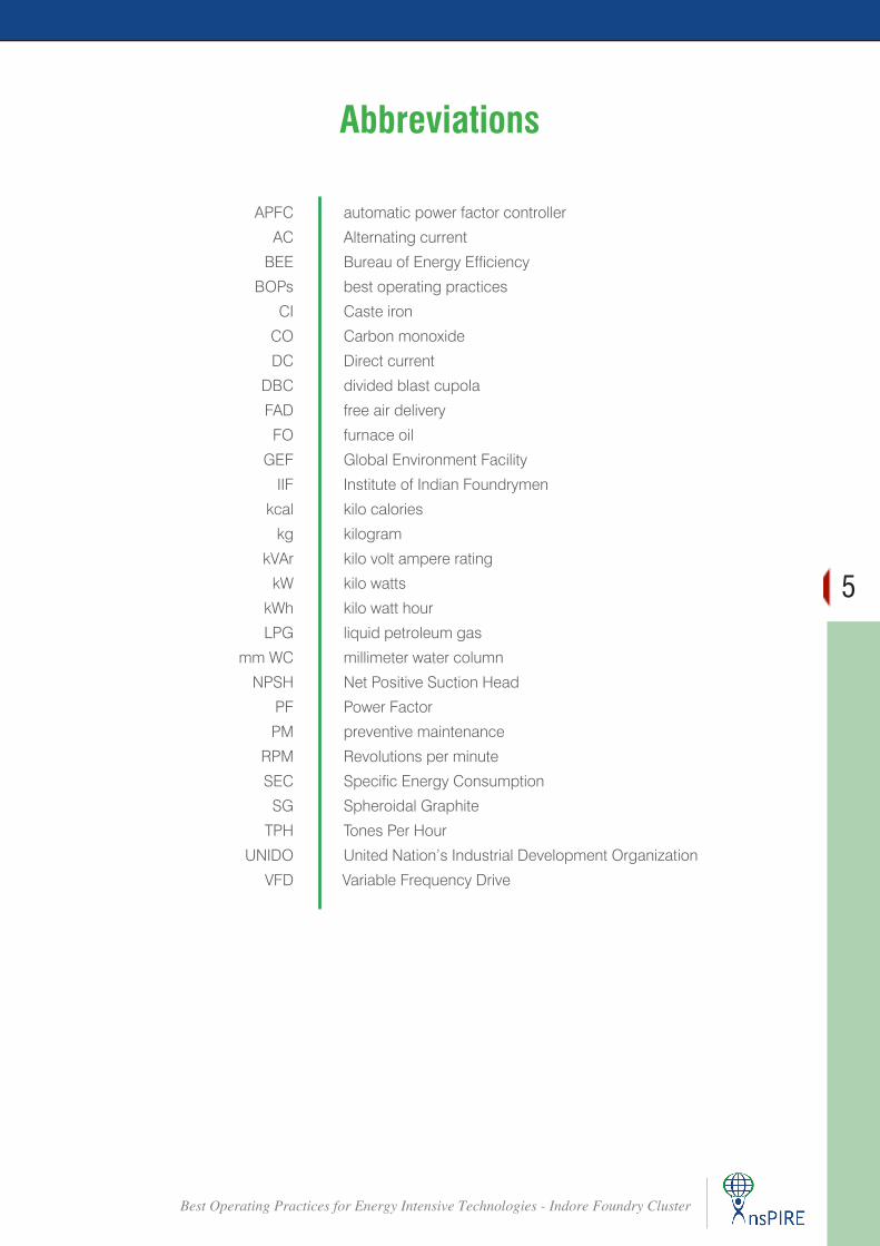
APFC automatic power factor controller
AC Alternating current
BEE Bureau of Energy Efficiency
BOPs best operating practices
CI Caste iron
CO Carbon monoxide
DC Direct current
DBC divided blast cupola
FAD free air delivery
FO furnace oil
GEF Global Environment Facility
IIF Institute of Indian Foundrymen
kcal kilo calories
kg kilogram
kVAr kilo volt ampere rating
kW kilo watts
kWh kilo watt hour
LPG liquid petroleum gas
mm WC millimeter water column
NPSH Net Positive Suction Head
PF Power Factor
PM preventive maintenance
RPM Revolutions per minute
SEC Specific Energy Consumption
SG Spheroidal Graphite
TPH Tones Per Hour
UNIDO United Nation’s Industrial Development Organization
VFD Variable Frequency Drive
Abbreviations
6
Best Operating Practices for Energy Intensive Technologies - Indore Foundry Cluster
IntroductionCHAPTER 1
1.1 Brief about the project The project titled “Promoting Energy Efficiency
and Renewable Energy in Selected MSME clusters in India” supported by Global Environment Facility (GEF), United Nations Industrial Development Organization (UNIDO), and Bureau of Energy Efficiency (BEE) aims to bring down the energy consumption in Indore Foundry cluster located in Indore (Madhya Pradesh) by supporting them to adopt Energy Efficient and Renewable Energy practices. This project is being implemented with support from local association which in this case is The Institute of Indian Foundrymen (IIF), Indore Chapter.
There are more than 70 SME foundry units operating in the various industrial pockets of the district. However, only 13 major units in the cluster are registered with association and are located in Ujjain, Dewas, Pithampur and Indore.
InsPIRE Network for Environment, New Delhi has been appointed as the executing agency to carry out the project activities in the cluster.
The sub-activities conducted by the InsPIRE Network for Environment under the proposed energy efficiency study in Indore Foundry Cluster include the following:
f Conducting Pre-activity Workshop
f Comprehensive energy audit in 6 foundry units
f Discussion with 3 cluster experts
f Discussion with 2 equipment suppliers
f Development of Best Operating Practices Manual for 5 energy intensive equipment
f Identification of monitoring parameters and measuring instruments
f Conducting 3 post-audit Workshops
1.2 Brief about the cluster and production process
Indore is one of the biggest industrial cluster belts of Madhya Pradesh. There are nearly 70 foundry units located in the cluster. However, only few major units are registered with IIF, Indore Chapter. These units are located in Dewas, Indore, Ujjain and Pithampur Industrial Estate. The key products manufactured by these units include Cast Iron (CI) castings, Spheroidal Graphite (SG) Iron castings, Investment casting and Sand castings. Most of these units have got local customer base which includes companies like Kirloskar Brothers, Jash Engineering, Avtech Ltd., Tata International, and BHEL Bhopal. The key sources of energy used in the cluster include electricity, kerosene oil, furnace oil and coke. There are two types of production process mainly observed in this cluster, investment casting and sand casting.
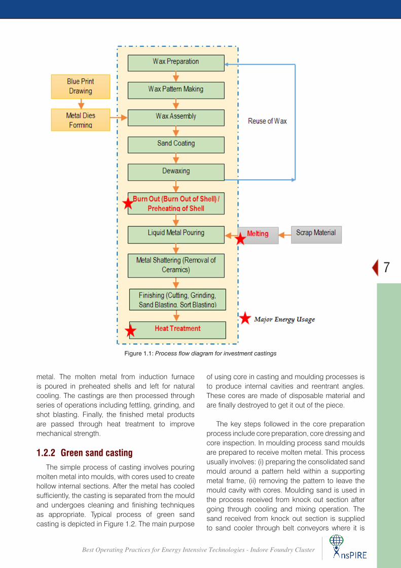
1.2.1 Investment casting processIndore is one of the biggest industrial cluster
belts of Madhya Pradesh. There are nearly 70 foundry units located in the cluster. These units are located in Dewas, Indore, Ujjain and Pithampur Industrial Estate. The key products manufactured by these units include Cast Iron (CI) castings, Spheroidal Graphite (SG) Iron castings, Investment casting and Sand castings. Most of these units have got local customer base which includes companies like Kirloskar Brothers, Jash Engineering, Avtech Ltd., Tata International, and BHEL Bhopal. The key sources of energy used in the cluster include electricity, kerosene oil, furnace oil and coke. There are two types of production process mainly observed in this cluster, investment casting and sand casting.
The scrap material to be poured in the shells is melted in electrical induction furnace. Scrap material is heated to around 1000 - 11000C after which molten metal composition is analyzed using spectrometer and accordingly, if required, correction is made to bring required composition of molten
7
Best Operating Practices for Energy Intensive Technologies - Indore Foundry Cluster
Figure 1.1: Process flow diagram for investment castings
metal. The molten metal from induction furnace is poured in preheated shells and left for natural cooling. The castings are then processed through series of operations including fettling, grinding, and shot blasting. Finally, the finished metal products are passed through heat treatment to improve mechanical strength.
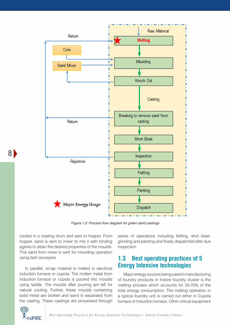
1.2.2 Green sand castingThe simple process of casting involves pouring
molten metal into moulds, with cores used to create hollow internal sections. After the metal has cooled sufficiently, the casting is separated from the mould and undergoes cleaning and finishing techniques as appropriate. Typical process of green sand casting is depicted in Figure 1.2. The main purpose
of using core in casting and moulding processes is to produce internal cavities and reentrant angles. These cores are made of disposable material and are finally destroyed to get it out of the piece.
The key steps followed in the core preparation process include core preparation, core dressing and core inspection. In moulding process sand moulds are prepared to receive molten metal. This process usually involves: (i) preparing the consolidated sand mould around a pattern held within a supporting metal frame, (ii) removing the pattern to leave the mould cavity with cores. Moulding sand is used in the process received from knock out section after going through cooling and mixing operation. The sand received from knock out section is supplied to sand cooler through belt conveyors where it is
8
Best Operating Practices for Energy Intensive Technologies - Indore Foundry Cluster
Figure 1.2: Process flow diagram for green sand castings
cooled in a rotating drum and sent to hopper. From hopper, sand is sent to mixer to mix it with binding agents to attain the desired properties of the moulds. This sand from mixer is sent for moulding operation using belt conveyers.
In parallel, scrap material is melted in electrical induction furnace or cupola. The molten metal from induction furnace or cupola is poured into moulds using laddle. The moulds after pouring are left for natural cooling. Further, these moulds containing solid metal are broken and sand is separated from the casting. These castings are processed through
series of operations including fettling, shot blast, grinding and painting and finally dispatched after due inspection.
1.3 Best operating practices of 5 Energy Intensive technologies
Major energy sources being used in manufacturing of foundry products in Indore foundry cluster is the melting process which accounts for 50-70% of the total energy consumption. The melting operation in a typical foundry unit is carried out either in Cupola furnace or Induction furnace. Other critical equipment
9
Best Operating Practices for Energy Intensive Technologies - Indore Foundry Cluster
in the foundry process involves electrical facility like motors, pumps, compressed air system etc. Thus, the two forms of energy being used in manufacturing of casting products in typical foundry unit are electrical energy and thermal energy. Electrical energy is being used in melting of charge in induction furnaces and operation of electrical utilities whereas thermal energy is being used in foundry melting operation like cupola and in some areas for the purpose of re-heating of stock.
The melting of raw material is either done using electricity in an induction furnace or coke in a cupola (conventional or divided blast type). Energy is also utilized through application of compressed air that are mainly used to operate molding machines, pneumatic grinders, mould cleaning and for other miscellaneous uses in a foundry. Cooling water circuit also plays a vital role in operation of induction furnace.
Like all manufacturing process, efficiency of a unit depends on the performance and efficiency of key technologies installed. The assignment envisages development of cluster specific ‘Best Operating Practices (BOPs)’ for the top 5 energy using equipment/process in the industry cluster on the basis of:
f process/technology used in the cluster f energy audits conducted in 6 foundry units in the
cluster f discussion with at least 3 experts in/around the
cluster f discussion with at least 2 equipment suppliers of
each equipment
Based on the outcome of the energy audits in 6 units under Indore foundry cluster and subsequent discussions with experts and equipment suppliers, following 5 technologies were identified and best operating practices corresponding to these technologies has been listed under subsequent chapters:
f Induction furnace f Cupola furnace f Re-heating furnace f Motors and pumps f Compressed air system
The list of experts and equipment suppliers discussed with, under the assignment, is placed at Annexure 1.
1.4 Outcome of discussion with experts/suppliers
As per the stipulated guidelines of the assignment, a series of meetings / discussions were held with experts / equipment suppliers to develop views and derive inputs towards development of best operating practices of the cluster. The various stakeholders that were involved while developing the best operating practices were:
f Beneficiary units. f Local experts / equipment suppliers f National level experts for the selected technology
With a target to disseminate the findings of the energy audit that were carried out in 6 identified units, stakeholders meeting were held in the following locations:
f 15th December, 2015 at Hotel Nandan Kanan, Dewas.
f 16th December, 2015 at Hotel Best Western, Indore
f 23rd December, 2015 at Hotel Monarch,
Pithampur
Brainstorming sessions during each stakeholder’s meeting were held to get a reflection on the importance of best operating practices in energy conservation and overall efficiency of the units. The members agreed that majority of foundry units under the Indore foundry cluster are using low-end technologies in their processes and utilities. Performance of most of these processes /equipment are poor as compared to the national and global benchmarks. A significant portion of energy consumption profile of the units depends primarily on its operating practices. Efficient operating practices can not only lead to reduction in energy consumption but also results in better equipment availability, lower breakdown, better product quality and overall optimum production efficiency in units.
Based on the energy audits in the selected units, it was revealed that the melting process i.e. induction furnace or cupola is the most energy intensive process in the cluster. Other important energy consuming equipments are motors, pumps, compressed air system and the process of re-heating of shell / moulds in oil fired furnace.
10
Best Operating Practices for Energy Intensive Technologies - Indore Foundry Cluster
Mr. Mitesh Raghuvanshi, Chairman, The Institute of Indian Foundrymen (IIF), Indore Chapter , during delivery of the key-note addresses in the stakeholder’s meeting stressed that most of the energy are wasted in inefficient practices which is mainly due to lack of awareness. Development of best operating practice document will boost the workers knowledge and skills in understanding and following the practices towards achieving energy conservation. Other participating members while agreeing to his point stated that most of the equipment fails due to poor maintenance. Machine downtime can be avoided significantly by introducing preventive maintenance practices as part of the best operating practices.
Based on the observations made during the 6 energy audits and subsequent discussions during stakeholders meeting, 5 key technologies were zeroed in under the Indore foundry cluster for the purpose of development of best operating practices. In order to take a detailed insight on the BOPs of the 5 key technologies, discussions were held with experts / suppliers at the local as well as national level. A summary of discussions held with various experts/suppliers (list provided in Annexure 1) on the need of BOPs; the critical equipment in the cluster and inputs related to BOPs for this critical equipment has been provided in the following sections.
Mr. Navin Goyal, MD, Essen Energy Technologies (P) Ltd., Indore and freelance foundry expert from Indore cluster, during discussion stressed on the need for development of a comprehensive best operating practice document for the cluster. Mr. Goyal emphasized that majority of energy loss is accounted for lack of knowledge and improper monitoring of key parameters. He cited the example of rewinded motor which are cheaper way of running the motor but the net impact is energy intensive as well not so economically promising on long run. This significantly effects efficiency of the unit.
Mr. Kamlesh Bhavsir, from Indo Air Compressor, during discussion reiterated the importance of designing a customized compressed air system for best utilization and efficiency. A compressor should be optimally located near to the site of application.
Mr. Bharat Tank, Electrotherm (India) Ltd., shared his practical experience of improvement achieved by adopting good operating practices. He particularly stressed on the requirement of charge processing
and segregation in order to obtain optimal charge density that are suitable for melting. Mr. Tank also informed that as a company policy, they extend the service of providing shop-floor training as part of their equipment commissioning and installation process.
Mr. S.K. Jain, Punjab State Council for Science and Technology, Chandigarh, during his discussion cited example of the Mandi Gobindgarh cluster which has improved through adoption of best operating practices and provision of training to the shop-floor personnel. Mr. Jain shared information on BOP for Cupola which has been developed by them under a similar program in Mandi Gobindgarh cluster. Mr. Jain also mentioned on the requirement of cross-cluster learning mechanism for adoption of best operating practices.
Mr. V.B. Mahindra, MD, Encon Thermal Engineers Ltd, Faridabad highlighted the importance of monitoring in case of re-heating furnace. Mr. Mahindra cited examples on the improvement of the life of the furnace with adoption of optimum refractory and insulation.
Dinesh Dholakia, An Induction furnace expert/ supplier from Inductotherm (India) Pvt. Ltd. suggested that BOPs would play a crucial role in providing technical know-how to the shop-floor people working in the Induction Furnaces. He said the utmost important points that should be considered in the Induction furnace is to Install linings as prescribed by the furnace manufacturer to get the optimum result for energy consumption. Selection of appropriate lining material, thickness and its sintering also play crucial role in energy saving.
Vasant Panchal, himself a cupola furnace expert/supplier representing Vitthal Enterprises, mentioned that there are many factors upon which the performance of the Cupola depends in terms of its energy efficient operations. The furnace feed composition and quality plays an important role in energy consumption in the furnace. Cupola operation also plays a significant role in energy consumption and overall efficiency of the furnace. The blast rate and pressure rate also have an important influence on cupola performance. He further emphasized that it’s very important that the Cupola bottom is dense, rammed properly and adequate slopes are provided towards the tap hole. The initial height of the bed above the tuyeres and the degree to which
11
Best Operating Practices for Energy Intensive Technologies - Indore Foundry Cluster
it is burned before the charging commences are vital factors governing, to a large extent, the metal temperature and melting rates obtained during the early part of the melt.
Dinesh Patidar from Shakti Pump (I) Ltd. while having a detail conversation recommended with respect to the motor that rather than rewinding a motors one should always give preference to replacement, since even a modest efficiency improvement may make it worthwhile to replace them with new, premium-efficiency motors rather than repair them. While doing that it is of course important
that an optimal size of the motor chosen.
Mr. Bhavik Patel, Director, Shah Enterprises, Surat highlighted the important of BOP for energy conservation During discussion, Mr. Patel pointed out that the load requirement for compressor for foundry and forging units , particularly, the MSME units, is highly uneven. In such case, use of VFDs can save
significant amount of energy. Regular cleaning of the suction filter of the compressor is another measure to save energy. Mr. Patel suggested that in case a unit has two or more varied requirement for compressed air with a difference of more than 1 bar, it is suggested to have different compressors for the different system requirements. Mr. Patel also suggested that leakages play an important role in determining the efficiency of the compressor and leakages should be addresses to the extent possible. Also, the pipes should not have much bends at the delivery side, since bends leads to drop in pressure.
While discussing on the importance of motors, Mr. Patel stressed on the replacement of conventional motors with energy efficient motors (I3 or I4). Mr. Patel also suggested the use of VFDs in case of varied loads. He also suggested motor should rather replace than re-wound as re-winding of motor leads to drop in efficiency.
12
Best Operating Practices for Energy Intensive Technologies - Indore Foundry Cluster
Best Operating Practices – Induction FurnaceCHAPTER 2
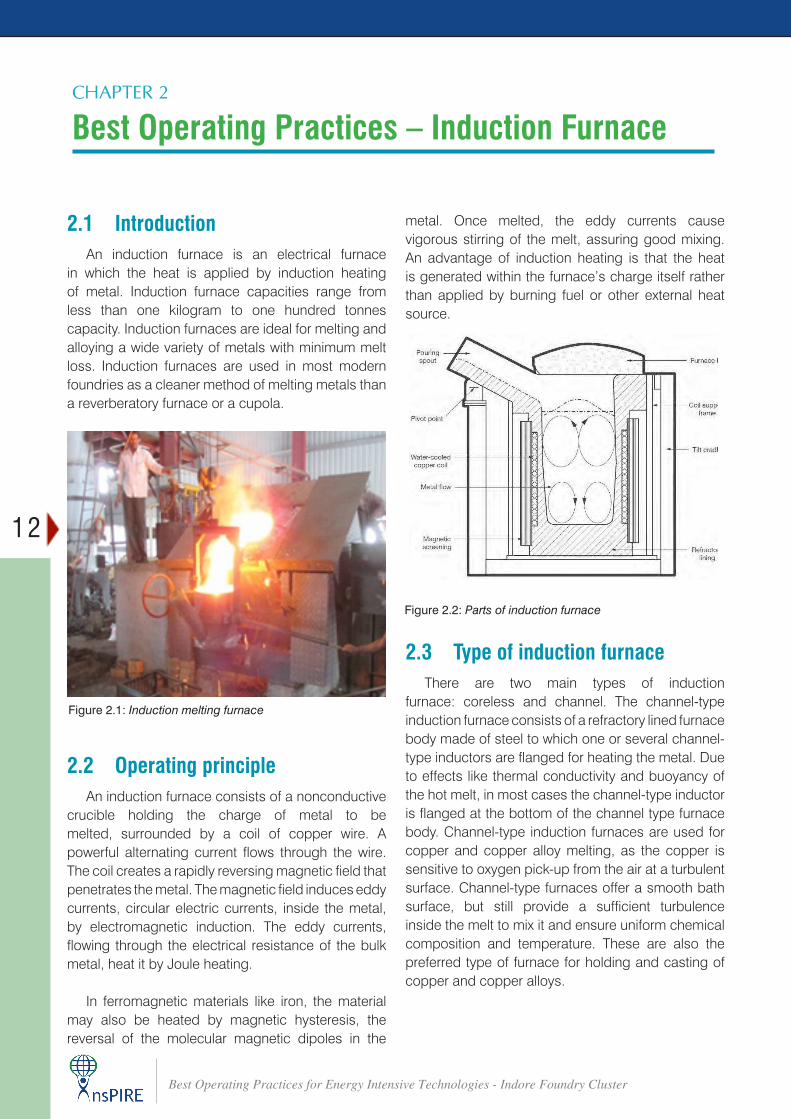
2.1 Introduction An induction furnace is an electrical furnace
in which the heat is applied by induction heating of metal. Induction furnace capacities range from less than one kilogram to one hundred tonnes capacity. Induction furnaces are ideal for melting and alloying a wide variety of metals with minimum melt loss. Induction furnaces are used in most modern foundries as a cleaner method of melting metals than a reverberatory furnace or a cupola.
2.2 Operating principleAn induction furnace consists of a nonconductive
crucible holding the charge of metal to be melted, surrounded by a coil of copper wire. A powerful alternating current flows through the wire. The coil creates a rapidly reversing magnetic field that penetrates the metal. The magnetic field induces eddy currents, circular electric currents, inside the metal, by electromagnetic induction. The eddy currents, flowing through the electrical resistance of the bulk metal, heat it by Joule heating.
In ferromagnetic materials like iron, the material may also be heated by magnetic hysteresis, the reversal of the molecular magnetic dipoles in the
Figure 2.1: Induction melting furnace
Figure 2.2: Parts of induction furnace
metal. Once melted, the eddy currents cause vigorous stirring of the melt, assuring good mixing. An advantage of induction heating is that the heat is generated within the furnace’s charge itself rather than applied by burning fuel or other external heat source.
2.3 Type of induction furnaceThere are two main types of induction
furnace: coreless and channel. The channel-type induction furnace consists of a refractory lined furnace body made of steel to which one or several channel-type inductors are flanged for heating the metal. Due to effects like thermal conductivity and buoyancy of the hot melt, in most cases the channel-type inductor is flanged at the bottom of the channel type furnace body. Channel-type induction furnaces are used for copper and copper alloy melting, as the copper is sensitive to oxygen pick-up from the air at a turbulent surface. Channel-type furnaces offer a smooth bath surface, but still provide a sufficient turbulence inside the melt to mix it and ensure uniform chemical composition and temperature. These are also the preferred type of furnace for holding and casting of copper and copper alloys.
13
Best Operating Practices for Energy Intensive Technologies - Indore Foundry Cluster
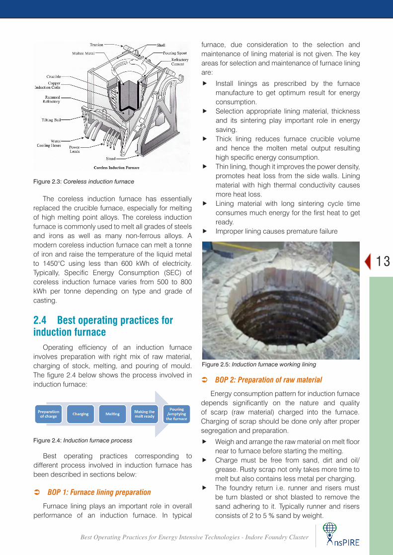
Figure 2.3: Coreless induction furnace
The coreless induction furnace has essentially replaced the crucible furnace, especially for melting of high melting point alloys. The coreless induction furnace is commonly used to melt all grades of steels and irons as well as many non-ferrous alloys. A modern coreless induction furnace can melt a tonne of iron and raise the temperature of the liquid metal to 1450°C using less than 600 kWh of electricity. Typically, Specific Energy Consumption (SEC) of coreless induction furnace varies from 500 to 800 kWh per tonne depending on type and grade of casting.
2.4 Best operating practices for induction furnace
Operating efficiency of an induction furnace involves preparation with right mix of raw material, charging of stock, melting, and pouring of mould. The figure 2.4 below shows the process involved in induction furnace:
Figure 2.4: Induction furnace process
Best operating practices corresponding to different process involved in induction furnace has been described in sections below:
 BOP 1: Furnace lining preparation
Furnace lining plays an important role in overall performance of an induction furnace. In typical
furnace, due consideration to the selection and maintenance of lining material is not given. The key areas for selection and maintenance of furnace lining are:
f Install linings as prescribed by the furnace manufacture to get optimum result for energy consumption.
f Selection appropriate lining material, thickness and its sintering play important role in energy saving.
f Thick lining reduces furnace crucible volume and hence the molten metal output resulting high specific energy consumption.
f Thin lining, though it improves the power density, promotes heat loss from the side walls. Lining material with high thermal conductivity causes more heat loss.
f Lining material with long sintering cycle time consumes much energy for the first heat to get ready.
f Improper lining causes premature failure
Figure 2.5: Induction furnace working lining
 BOP 2: Preparation of raw material
Energy consumption pattern for induction furnace depends significantly on the nature and quality of scarp (raw material) charged into the furnace. Charging of scrap should be done only after proper segregation and preparation.
f Weigh and arrange the raw material on melt floor near to furnace before starting the melting.
f Charge must be free from sand, dirt and oil/grease. Rusty scrap not only takes more time to melt but also contains less metal per charging.
f The foundry return i.e. runner and risers must be turn blasted or shot blasted to remove the sand adhering to it. Typically runner and risers consists of 2 to 5 % sand by weight.
14
Best Operating Practices for Energy Intensive Technologies - Indore Foundry Cluster
f Keep exact weight of alloys ready before charging, as alloys are very expensive. Proper handling will not only reduce wastage but also reduce time lost in alloying.
f The maximum size of single piece of metal/scrap should not be more than 1/3rd. of diameter of furnace crucible.
f There should be no or less sharp edges, particularly in case of heavy and bulky scrap, as this may damage the refractory.
 BOP 3: Scrap Charging
Subsequent to the preparation of raw material, next step involves charging of scrap into the furnace. Melting efficiency of an induction furnace depends predominantly of the charging process.
f Size of scrap is an important parameter to reduce energy consumption. The scrap charge should be as dense as possible. Lesser the air pocket between scrap pieces, more is the power density, higher the heat conductivity, faster melting with least energy consumption. Use small pieces of scrap, to the extent possible, to get optimum result.
f Avoid charging of furnace beyond the coil level, i.e. charging the furnace to its capacity.
f Proper charge sequence must be followed. Bigger size metal first followed by smaller size should be charged and gaps must be filled by turnings and boring.
f Avoid introduction of wet or damp metal in melt, this may cause explosion.
 BOP 4: Power Input
The power input provided for running an induction furnace during its melting operation has an important role on the overall energy consumption of the unit.
f Run furnace at maximum power since beginning. Maximum power input increases rate of melting and hence reduces cycle time of the heat.
f Power factor to be maintained near to one. f Ensure no voltage drop from the source.
 BOP 5: De-slagging and sampling
Formation of slag in the furnace wall should be avoided as it leads to increase in energy consumption and decrease furnace life.
f Carry out de-slagging once the furnace is full with molten metal and has attained temperature of 1350 -1400 0C . Prior to it, slag removing tools should be brought near to the furnace and kept ready.
f Avoid slag deposition on lining by complete removal of slag. After de-slagging, sample should be taken and sent to chemical laboratory. Use of Carbon equivalent instrument gives faster estimation of bath composition hence shortens the heat time.
 BOP 6: Avoiding unnecessary superheating of bath
Determining the correct tap temperature plays a significant role in energy consumption. Unnecessary superheating of metal bath at times has detrimental impact of the furnace performance.
f Decide superheating temperature based on final pouring temperature of a component and temperature loss during transfer of metal to pouring zone. Avoid unnecessary superheating of metal.
f Measure and monitor metal bath temperature in every heat. .
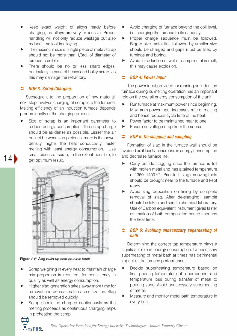
Figure 2.6: Slag build-up near crucible neck
f Scrap weighing in every heat to maintain charge mix proportion is required, for consistency in quality as well as energy consumption.
f Higher slag generation takes away more time for removal and decreases furnace utilization. Slag should be removed quickly
f Scrap should be charged continuously as the melting proceeds as continuous charging helps in preheating the scrap.
15
Best Operating Practices for Energy Intensive Technologies - Indore Foundry Cluster
through homogenization of metal with some variation coming from melting furnace.
 BOP 9: Production scheduling
Equipment efficiency can be optimized by a well-laid production schedule. Equalizing of loads between shifts plays an important role in reduction of energy consumption.
f Maintain appropriate production plan for equalizing the metal load in all shifts.
f Maintain production planning such that the rate of metal consumption is higher than the rate of metal generation.
f Optimize the peak output power of the melt power supply, saving money on demand charges.
f It is suggested to melt fewer days per week and more hours per day, if practical. This alternative will save on energy charges because you will be spending less time holding molten metal in the furnace at that temperature. It also will increase refractory life of the furnace.
 BOP 10: Preventive maintenance
Increasing equipment availability should be prioritized with an aim to reduce system breakdown and production downtime.
f Develop and maintain a well-defined Preventive Maintenance (PM) schedule with frequency for the furnace and all auxiliary equipment.
f Periodic infrared scans of all equipment to be done to eliminate hot spots in the furnace assembly, the power supply, interconnecting bus bar, water-cooled leads etc.
f It is suggested to have proper maintenance checks for the water-cooled leads. A furnace’s water-cooled leads can produce unnecessary electrical losses if they are not properly maintained or configured. If they are old and have gone through many cycles of furnace tilting, there may be broken cables inside the leads that cannot be seen but cause higher resistance in the lead and higher electrical losses. Leads should be tied together and polarized. Leads that are allowed to split apart from each other will have higher electrical losses than those that are bundled together properly.
 BOP 7: Maximize equipment utilization:
Furnace should be utilized to its optimum level for better output. Operating practices for optimizing furnace efficiency are:
f Maintain short and optimum holding times for molten metal.
f Maintain short and optimum charging time in the furnace. Avoid manual charging to the extent possible as it can be a long, tedious and dangerous process. In addition, with manual charging, it is difficult to keep pace with full power melting and power has to be throttled back. Long charging times mean low equipment utilization.
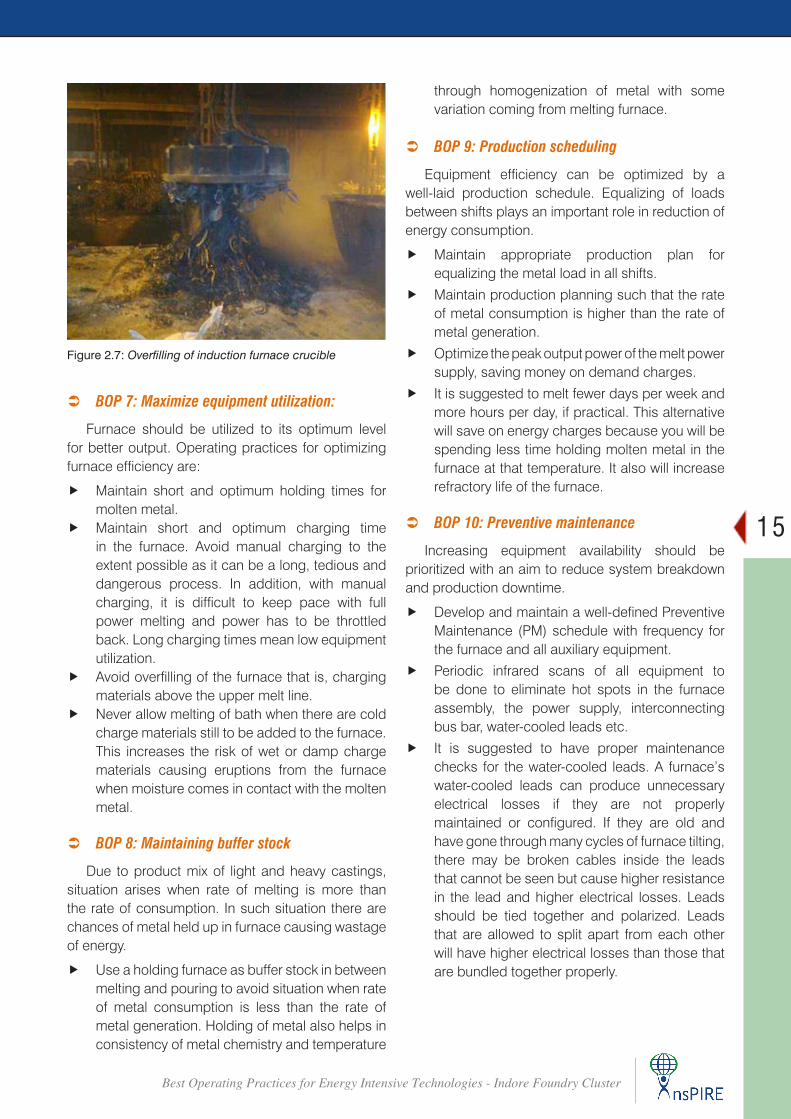
f Avoid overfilling of the furnace that is, charging materials above the upper melt line.
f Never allow melting of bath when there are cold charge materials still to be added to the furnace. This increases the risk of wet or damp charge materials causing eruptions from the furnace when moisture comes in contact with the molten metal.
 BOP 8: Maintaining buffer stock
Due to product mix of light and heavy castings, situation arises when rate of melting is more than the rate of consumption. In such situation there are chances of metal held up in furnace causing wastage of energy.
f Use a holding furnace as buffer stock in between melting and pouring to avoid situation when rate of metal consumption is less than the rate of metal generation. Holding of metal also helps in consistency of metal chemistry and temperature
Figure 2.7: Overfilling of induction furnace crucible
16
Best Operating Practices for Energy Intensive Technologies - Indore Foundry Cluster
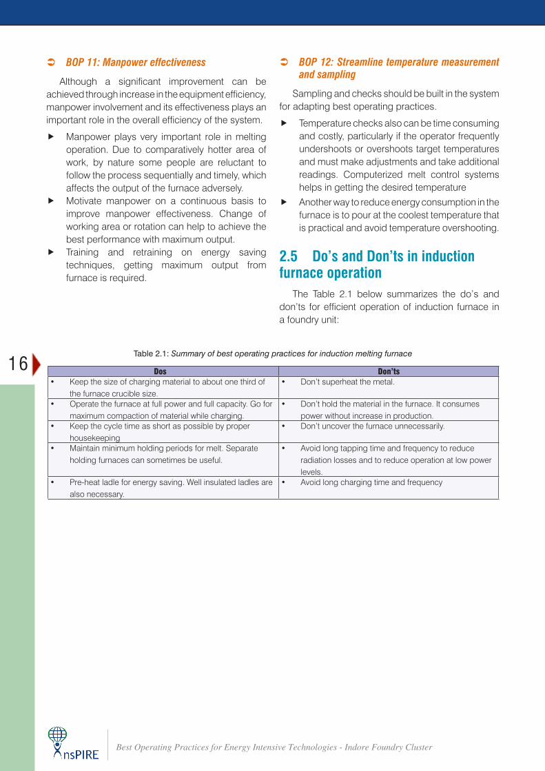
Dos Don’ts• Keep the size of charging material to about one third of
the furnace crucible size.• Don’t superheat the metal.
• Operate the furnace at full power and full capacity. Go for maximum compaction of material while charging.
• Don’t hold the material in the furnace. It consumes power without increase in production.
• Keep the cycle time as short as possible by proper housekeeping
• Don’t uncover the furnace unnecessarily.
• Maintain minimum holding periods for melt. Separate holding furnaces can sometimes be useful.
• Avoid long tapping time and frequency to reduce radiation losses and to reduce operation at low power levels.
• Pre-heat ladle for energy saving. Well insulated ladles are also necessary.
• Avoid long charging time and frequency
Table 2.1: Summary of best operating practices for induction melting furnace
 BOP 11: Manpower effectiveness
Although a significant improvement can be achieved through increase in the equipment efficiency, manpower involvement and its effectiveness plays an important role in the overall efficiency of the system.
f Manpower plays very important role in melting operation. Due to comparatively hotter area of work, by nature some people are reluctant to follow the process sequentially and timely, which affects the output of the furnace adversely.
f Motivate manpower on a continuous basis to improve manpower effectiveness. Change of working area or rotation can help to achieve the best performance with maximum output.
f Training and retraining on energy saving techniques, getting maximum output from furnace is required.
 BOP 12: Streamline temperature measurement and sampling
Sampling and checks should be built in the system for adapting best operating practices.
f Temperature checks also can be time consuming and costly, particularly if the operator frequently undershoots or overshoots target temperatures and must make adjustments and take additional readings. Computerized melt control systems helps in getting the desired temperature
f Another way to reduce energy consumption in the furnace is to pour at the coolest temperature that is practical and avoid temperature overshooting.
2.5 Do’s and Don’ts in induction furnace operation
The Table 2.1 below summarizes the do’s and don’ts for efficient operation of induction furnace in a foundry unit:
17
Best Operating Practices for Energy Intensive Technologies - Indore Foundry Cluster
Best Operating Practices – Cupola Furnace CHAPTER 3
3.1 IntroductionCupola, which is the most commonly used melting
furnace in the Indian foundries, is also the most energy intensive operation. It accounts for up to 50% of a foundry’s total energy consumption and is a prime candidate to focus attention, for improving end use energy efficiency in a foundry. The cupola can be made almost any practical size. The size of a cupola is expressed in diameters and can range from 1.5 to 13 feet (0.5 to 4.0 m). The overall shape is cylindrical and the equipment is arranged vertically, usually supported by four legs. The overall look is similar to a large smokestack.
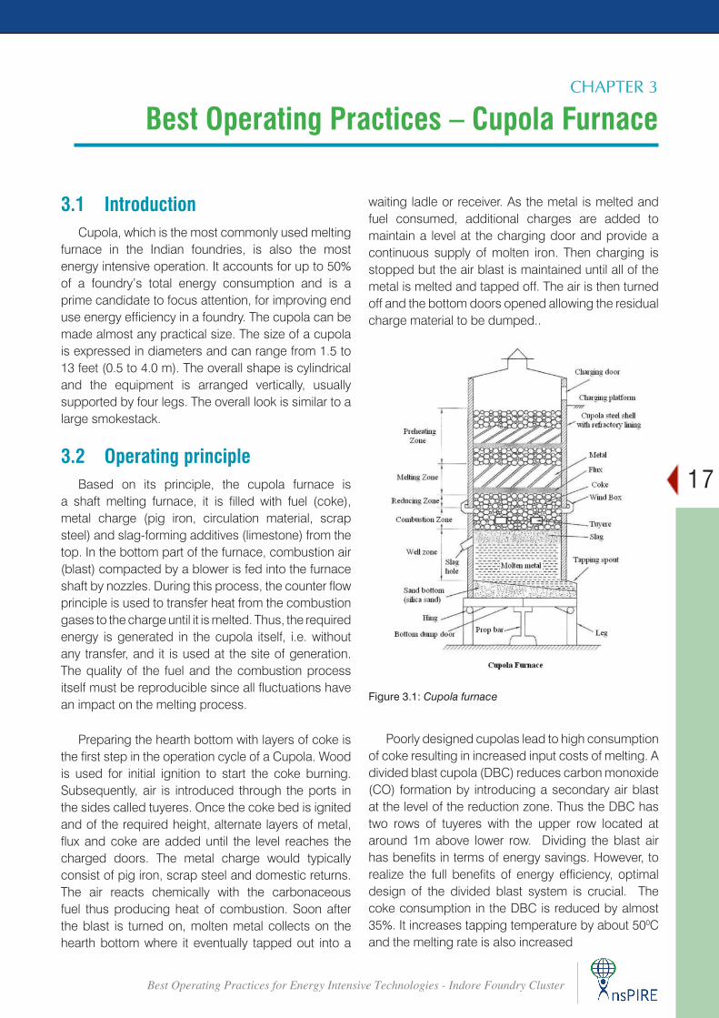
3.2 Operating principleBased on its principle, the cupola furnace is
a shaft melting furnace, it is filled with fuel (coke), metal charge (pig iron, circulation material, scrap steel) and slag-forming additives (limestone) from the top. In the bottom part of the furnace, combustion air (blast) compacted by a blower is fed into the furnace shaft by nozzles. During this process, the counter flow principle is used to transfer heat from the combustion gases to the charge until it is melted. Thus, the required energy is generated in the cupola itself, i.e. without any transfer, and it is used at the site of generation. The quality of the fuel and the combustion process itself must be reproducible since all fluctuations have an impact on the melting process.
Preparing the hearth bottom with layers of coke is the first step in the operation cycle of a Cupola. Wood is used for initial ignition to start the coke burning. Subsequently, air is introduced through the ports in the sides called tuyeres. Once the coke bed is ignited and of the required height, alternate layers of metal, flux and coke are added until the level reaches the charged doors. The metal charge would typically consist of pig iron, scrap steel and domestic returns. The air reacts chemically with the carbonaceous fuel thus producing heat of combustion. Soon after the blast is turned on, molten metal collects on the hearth bottom where it eventually tapped out into a
Figure 3.1: Cupola furnace
waiting ladle or receiver. As the metal is melted and fuel consumed, additional charges are added to maintain a level at the charging door and provide a continuous supply of molten iron. Then charging is stopped but the air blast is maintained until all of the metal is melted and tapped off. The air is then turned off and the bottom doors opened allowing the residual charge material to be dumped..
Poorly designed cupolas lead to high consumption of coke resulting in increased input costs of melting. A divided blast cupola (DBC) reduces carbon monoxide (CO) formation by introducing a secondary air blast at the level of the reduction zone. Thus the DBC has two rows of tuyeres with the upper row located at around 1m above lower row. Dividing the blast air has benefits in terms of energy savings. However, to realize the full benefits of energy efficiency, optimal design of the divided blast system is crucial. The coke consumption in the DBC is reduced by almost 35%. It increases tapping temperature by about 500C and the melting rate is also increased
18
Best Operating Practices for Energy Intensive Technologies - Indore Foundry Cluster
3.3 Best operating practices for cupola furnace
 BOP 1: Cupola base
The base of the cupola plays a significant role in proper functioning of the cupola and flow of hot metal from the cupola. Following points should be considered while making the base of the cupola:
f Ensure that the bottom sand is free from impurities, iron, etc., and that it has the proper moisture and clay content.
f The bottom should be dense, correctly rammed, heeled up around the wall and sloping towards the tap hole.
 BOP 2: Preparation of coke bed
The most important part in the successful operation of a cupola is the preparation of the coke bed. The initial height of the bed above the tuyeres and the degree to which it is burned before the charging commences are vital factors governing, to a large extent, the metal temperature and melting rates obtained during the early part of the melt. Following are main steps that needs to be followed:
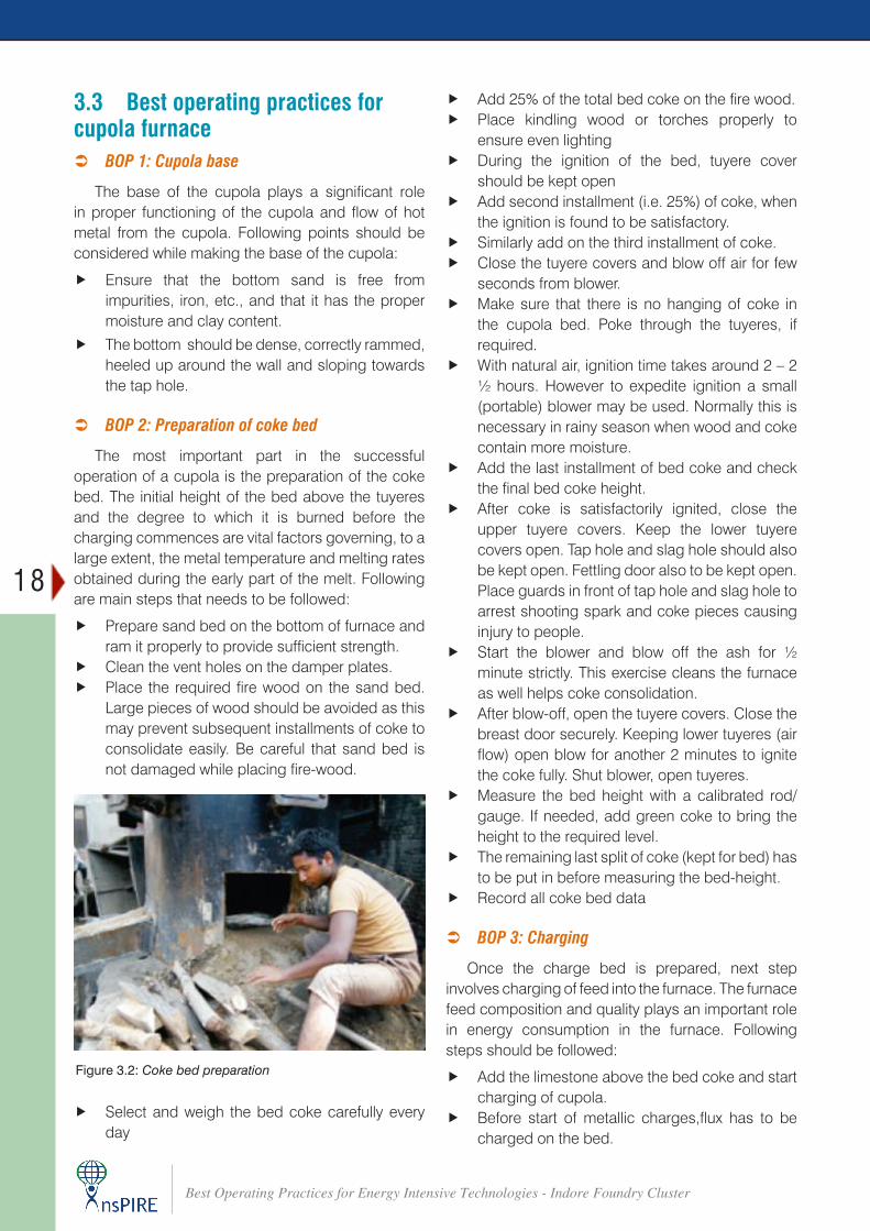
f Prepare sand bed on the bottom of furnace and ram it properly to provide sufficient strength.
f Clean the vent holes on the damper plates. f Place the required fire wood on the sand bed.
Large pieces of wood should be avoided as this may prevent subsequent installments of coke to consolidate easily. Be careful that sand bed is not damaged while placing fire-wood.
f Add 25% of the total bed coke on the fire wood. f Place kindling wood or torches properly to
ensure even lighting f During the ignition of the bed, tuyere cover
should be kept open f Add second installment (i.e. 25%) of coke, when
the ignition is found to be satisfactory. f Similarly add on the third installment of coke. f Close the tuyere covers and blow off air for few
seconds from blower. f Make sure that there is no hanging of coke in
the cupola bed. Poke through the tuyeres, if required.
f With natural air, ignition time takes around 2 – 2 ½ hours. However to expedite ignition a small (portable) blower may be used. Normally this is necessary in rainy season when wood and coke contain more moisture.
f Add the last installment of bed coke and check the final bed coke height.
f After coke is satisfactorily ignited, close the upper tuyere covers. Keep the lower tuyere covers open. Tap hole and slag hole should also be kept open. Fettling door also to be kept open. Place guards in front of tap hole and slag hole to arrest shooting spark and coke pieces causing injury to people.
f Start the blower and blow off the ash for ½ minute strictly. This exercise cleans the furnace as well helps coke consolidation.
f After blow-off, open the tuyere covers. Close the breast door securely. Keeping lower tuyeres (air flow) open blow for another 2 minutes to ignite the coke fully. Shut blower, open tuyeres.
f Measure the bed height with a calibrated rod/gauge. If needed, add green coke to bring the height to the required level.
f The remaining last split of coke (kept for bed) has to be put in before measuring the bed-height.
f Record all coke bed data
 BOP 3: Charging
Once the charge bed is prepared, next step involves charging of feed into the furnace. The furnace feed composition and quality plays an important role in energy consumption in the furnace. Following steps should be followed:
f Add the limestone above the bed coke and start charging of cupola.
f Before start of metallic charges,flux has to be charged on the bed.
Figure 3.2: Coke bed preparation
f Select and weigh the bed coke carefully every day

19
Best Operating Practices for Energy Intensive Technologies - Indore Foundry Cluster
f The flux (lime stone in most case) size should be ¾ – 2 inch for small cupolas.
f Clean charge should be fed into the furnace f The acid insoluble content in flux stone should
not exceed 5% of its total weight f The diagonal dimension of a single piece of metal
should be less than 1/3rd the hearth diameter to ensure that the cupola operates efficiently
f The weight of a single piece of metal should be limited to 1% of the hourly melting rate.
f Heavy (thick) sections of scrap should be avoided in first 5 charges.
f The quality of purchased scrap should meet the specifications of the product to be manufactured
f The charging sequence of the metal must be maintained
Figure 3.3: Ignition of coke bed
Figure 3.4: Charging of cupola
f When the stack is full, close the tuyere covers and start the blower. The stack should always be full with charge material during the operations.
f Once charging starts, it has to be continued till, (i) the cupola shaft is filled up with the charging material, (ii) the cupola is lit up, and (iii) the blower and tuyeres are switched on
f Use light scrap for filling up to achieve initial tap temperatures.
f The tuyeres should be kept clear from the slag deposition at all times.
f Ensure that the cupola is full before turning on the blast.
 BOP 4: Melting
Melting commences once charging of feed is complete and after ensuring the cupola is full. Following steps should be followed for efficient melting:
f Establish the proper initial blast rate and maintain it right through to tap-out.
f Dry and thoroughly pre-heat all runners and ladles daily.
f Use only dry inoculants. If the alloy is wet, proper inoculation will not take place leading to pinholes or other defects.
f Black top gas suggests that the blower motor is blocked or greasy scraps have been used in the charge.
f If the stack discharge appears reddish, the reasons could be:
® Oxidizing conditions on account of low bed or high blast
® Excessive amount of rust in the charge material
® Scaffolding or hanging of charge f Strong flame and high temperature at the charge
door indicates a high bed and excessive coke splits between charges, or low stack height in the cupola.
f A blue-pink flame moving up and down the walls and clinging to projections indicates good melting conditions.
f During melting, burn-back occurs above the tuyeres in the melting zone. The following factors contribute to burn-back:
® Low temperature of the melting zone ® High blast rate ® Incorrect tuyere dimensions ® Uneven charge distribution.
20
Best Operating Practices for Energy Intensive Technologies - Indore Foundry Cluster
f The melting rate of a cupola using low ash (<14%) should be about 10 tonnes/hr/m2 and for cupola using high ash coke (>30%) should be about 7 tonnes/hr/m2. If the melting rate is lower, check the parameters of cupola blower.
 BOP 5: Cupola operation
Cupola operation plays a significant role in energy consumption and overall efficiency of the furnace. Some useful guidelines for efficient operation of a cupola are:
f Close tuyere covers, plug tap hole and slag hole. Allow some time for the feed material to absorb heat. This is called soaking time. Generally 10 minutes is sufficient.
f Switch on blower and note time. f Look for droplets of molten metal through the
tuyere peep-hole and note time. Droplets should be visible approximately after 7 – 10 minutes of starting the blower.
f After blow on, first tapping can be made approximately within 15 – 20 minutes. If the tap – hole gets jammed due to cold metal or any other reason, do not attempt to open it by hammer. Put some lighted cotton waste and charcoal at the tap-hole and apply oxygen with a lancing tube (M.S. pipe of 2 mm bore diameter) at regulated pressure.
f Oxygen cylinder (kept for lancing) must have a regulator fitted on. Pneumatic pipe used for this purpose must match (bore) with the lancing pipe. No leak should be there.
f The oxygen will melt the solidified metal at the tap-hole.
f In intermittent tapped cupolas, the slag hole should be opened after 2/3rd tapping.
f Note down slag conditions i.e. fluidity/viscous or fluid. Ideal colour should be bottle green.
f Constant vigil should be kept to ensure that at no time charge stack level falls. If due to any reason this happens. Shut off the blower, open tuyere covers, fill up the stack, close tuyere covers and start blower.
f Maintain proper sequence of charging. Bridging or hanging inside the cupola should be taken care of immediately. Fall in stack level, bridging or hanging affects quality and chemistry of molten metal.
f Maintain a log-book recording every detail for every heat. Some of the important parameters (apart from the weight of each charge) that
must be recorded in the sheet are bed height, weight of bed coke (this may vary with the bulk density), bed light-up time, time taken for coke ignition, time taken and number of charges to fill up the stack at the beginning, blower on time, any interruption during melting, its cause, end time of melt i.e. blower off, last tapping, drain out, bottom door opened and bed dropped. All timings must be meticulously recorded.
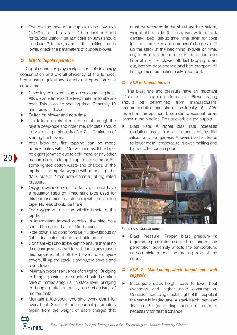
 BOP 6: Cupola blower
The blast rate and pressure have an important influence on cupola performance. Blower rating should be determined from manufacturers’ recommendation and should be ideally 15 - 20% more than the optimum blast rate, to account for air losses in the pipeline. Do not overblow the cupola.
f Blast Rate: A higher blast rate increases oxidation loss of iron and other elements like silicon and manganese. A lower blast air leads to lower metal temperature, slower melting and higher coke consumption.
f Blast Pressure: Proper blast pressure is required to penetrate the coke bed. Incorrect air penetration adversely affects the temperature, carbon pick-up and the melting rate of the cupola.
 BOP 7: Maintaining stack height and well capacity
f Inadequate stack height leads to lower heat exchange and higher coke consumption. Consider increasing stack height of the cupola if the same is inadequate. A stack height between 16 ft to 22 ft (depending upon its diameter) is necessary for heat exchange.
Figure 3.5: Cupola blower
21
Best Operating Practices for Energy Intensive Technologies - Indore Foundry Cluster
f Do not increase well capacity more than what is desired. Every inch increase in the well depth reduces molten metal temperature by 40C. For intermittently tapped cupola, the well capacity should match the capacity of the ladle. For continuously tapped cupola, a minimum well depth, ideally of 300 mm is usually sufficient.
 BOP 8: Optimum refractory lining
f Use IS 8 grade fire bricks for lining the cupola. For double brick lined cupola, IS 6 grade bricks can be used in the rear side towards cupola shell. Do not use cracked and corner chipped bricks in the melting zone. Store the fire bricks in a shed to keep them dry.
f Fire clay should be soaked for at least 48 hours before use. This is required to develop its plasticity and adhesive quality required for joining bricks. Provide proper tools, such as hammer, trowel (or karni), mallet etc. to operators. Make diameter gauge for the tap-hole. Provide a lighting arrangement inside the cupola during repair. Bricks should be set 15-20 mm away from the Cupola shell. Pack this gap with dry foundry sand. Mortar applied on the bricks should not be of thick layer. It should be just enough so that the brick sets firmly on to the other. Excess spilled mortar to be wiped off. Excess or thick layer of mortar are weak points through which molten metal can penetrate to the shell causing hot spots on the shell. 20 / 25 mm thick layer of ganister over the newly lined bricks is advisable.
f Cupola must be properly lined/ repaired after each melt. Correct internal diameter (ID) needs to be maintained.
f Patching material can be used to repair the refractory lining if erosion/burn-back is less than 3 inch (75 mm).
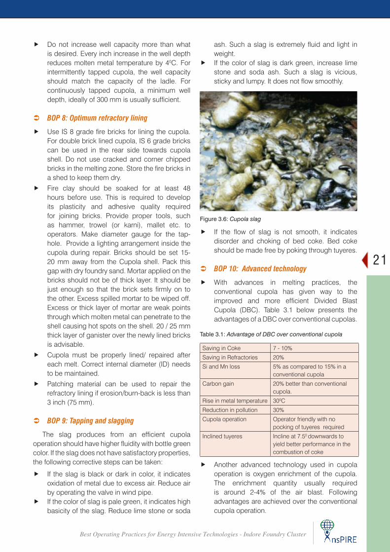
 BOP 9: Tapping and slagging
The slag produces from an efficient cupola operation should have higher fluidity with bottle green color. If the slag does not have satisfactory properties, the following corrective steps can be taken:
f If the slag is black or dark in color, it indicates oxidation of metal due to excess air. Reduce air by operating the valve in wind pipe.
f If the color of slag is pale green, it indicates high basicity of the slag. Reduce lime stone or soda
ash. Such a slag is extremely fluid and light in weight.
f If the color of slag is dark green, increase lime stone and soda ash. Such a slag is vicious, sticky and lumpy. It does not flow smoothly.
f If the flow of slag is not smooth, it indicates disorder and choking of bed coke. Bed coke should be made free by poking through tuyeres.
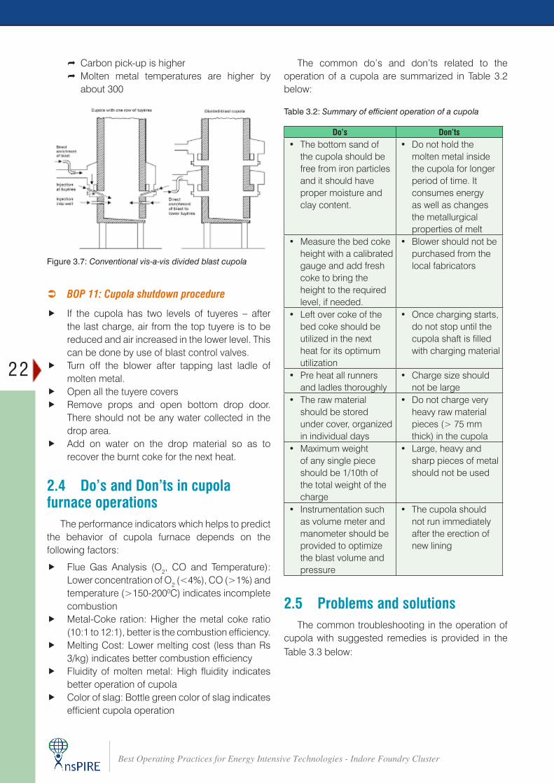
 BOP 10: Advanced technology
f With advances in melting practices, the conventional cupola has given way to the improved and more efficient Divided Blast Cupola (DBC). Table 3.1 below presents the advantages of a DBC over conventional cupolas.
Figure 3.6: Cupola slag
Saving in Coke 7 - 10%
Saving in Refractories 20%
Si and Mn loss 5% as compared to 15% in a conventional cupola
Carbon gain 20% better than conventional cupola.
Rise in metal temperature 300C
Reduction in pollution 30%
Cupola operation Operator friendly with no pocking of tuyeres required
Inclined tuyeres Incline at 7.50 downwards to yield better performance in the combustion of coke
Table 3.1: Advantage of DBC over conventional cupola
f Another advanced technology used in cupola operation is oxygen enrichment of the cupola. The enrichment quantity usually required is around 2-4% of the air blast. Following advantages are achieved over the conventional cupola operation.
22
Best Operating Practices for Energy Intensive Technologies - Indore Foundry Cluster
Figure 3.7: Conventional vis-a-vis divided blast cupola
® Carbon pick-up is higher ® Molten metal temperatures are higher by about 300
Do’s Don’ts• The bottom sand of
the cupola should be free from iron particles and it should have proper moisture and clay content.
• Do not hold the molten metal inside the cupola for longer period of time. It consumes energy as well as changes the metallurgical properties of melt
• Measure the bed coke height with a calibrated gauge and add fresh coke to bring the height to the required level, if needed.
• Blower should not be purchased from the local fabricators
• Left over coke of the bed coke should be utilized in the next heat for its optimum utilization
• Once charging starts, do not stop until the cupola shaft is filled with charging material
• Pre heat all runners and ladles thoroughly
• Charge size should not be large
• The raw material should be stored under cover, organized in individual days
• Do not charge very heavy raw material pieces (> 75 mm thick) in the cupola
• Maximum weight of any single piece should be 1/10th of the total weight of the charge
• Large, heavy and sharp pieces of metal should not be used
• Instrumentation such as volume meter and manometer should be provided to optimize the blast volume and pressure
• The cupola should not run immediately after the erection of new lining
Table 3.2: Summary of efficient operation of a cupola
The common do’s and don’ts related to the operation of a cupola are summarized in Table 3.2 below:
 BOP 11: Cupola shutdown procedure
f If the cupola has two levels of tuyeres – after the last charge, air from the top tuyere is to be reduced and air increased in the lower level. This can be done by use of blast control valves.
f Turn off the blower after tapping last ladle of molten metal.
f Open all the tuyere covers f Remove props and open bottom drop door.
There should not be any water collected in the drop area.
f Add on water on the drop material so as to recover the burnt coke for the next heat.
2.4 Do’s and Don’ts in cupola furnace operations
The performance indicators which helps to predict the behavior of cupola furnace depends on the following factors:
f Flue Gas Analysis (O2, CO and Temperature): Lower concentration of O2 (<4%), CO (>1%) and temperature (>150-2000C) indicates incomplete combustion
f Metal-Coke ration: Higher the metal coke ratio (10:1 to 12:1), better is the combustion efficiency.
f Melting Cost: Lower melting cost (less than Rs 3/kg) indicates better combustion efficiency
f Fluidity of molten metal: High fluidity indicates better operation of cupola
f Color of slag: Bottle green color of slag indicates efficient cupola operation
2.5 Problems and solutionsThe common troubleshooting in the operation of
cupola with suggested remedies is provided in the Table 3.3 below:
23
Best Operating Practices for Energy Intensive Technologies - Indore Foundry Cluster
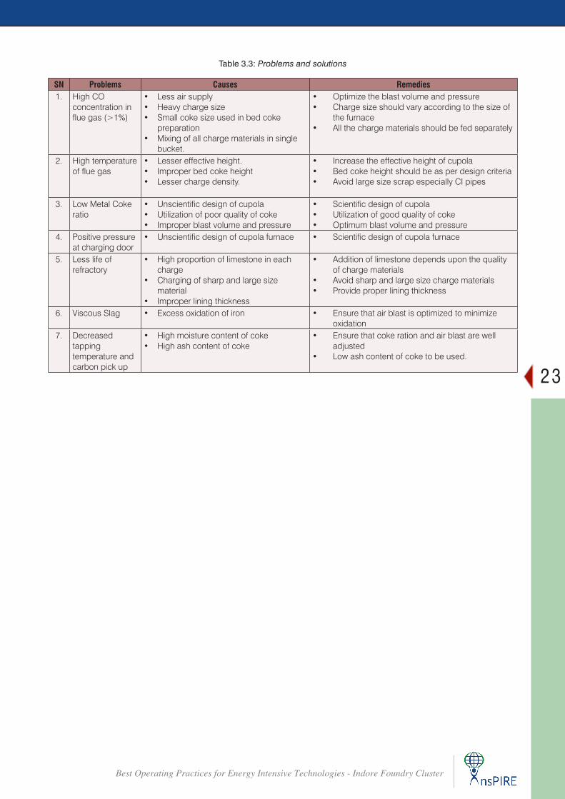
Table 3.3: Problems and solutions
SN Problems Causes Remedies1. High CO
concentration in flue gas (>1%)
• Less air supply• Heavy charge size• Small coke size used in bed coke
preparation• Mixing of all charge materials in single
bucket.
• Optimize the blast volume and pressure• Charge size should vary according to the size of
the furnace• All the charge materials should be fed separately
2. High temperature of flue gas
• Lesser effective height.• Improper bed coke height• Lesser charge density.
• Increase the effective height of cupola• Bed coke height should be as per design criteria• Avoid large size scrap especially CI pipes
3. Low Metal Coke ratio
• Unscientific design of cupola• Utilization of poor quality of coke• Improper blast volume and pressure
• Scientific design of cupola• Utilization of good quality of coke• Optimum blast volume and pressure
4. Positive pressure at charging door
• Unscientific design of cupola furnace • Scientific design of cupola furnace
5. Less life of refractory
• High proportion of limestone in each charge
• Charging of sharp and large size material
• Improper lining thickness
• Addition of limestone depends upon the quality of charge materials
• Avoid sharp and large size charge materials • Provide proper lining thickness
6. Viscous Slag • Excess oxidation of iron • Ensure that air blast is optimized to minimize oxidation
7. Decreased tapping temperature and carbon pick up
• High moisture content of coke• High ash content of coke
• Ensure that coke ration and air blast are well adjusted
• Low ash content of coke to be used.
24
Best Operating Practices for Energy Intensive Technologies - Indore Foundry Cluster
Best Operating Practices – Compressed Air SystemCHAPTER 4
4.1 IntroductionCompressed air is a very useful and valuable utility,
which must be managed to optimize overall system performance. In a foundry unit air compressors are used in the machine shop for pneumatic equipment and machine tools.
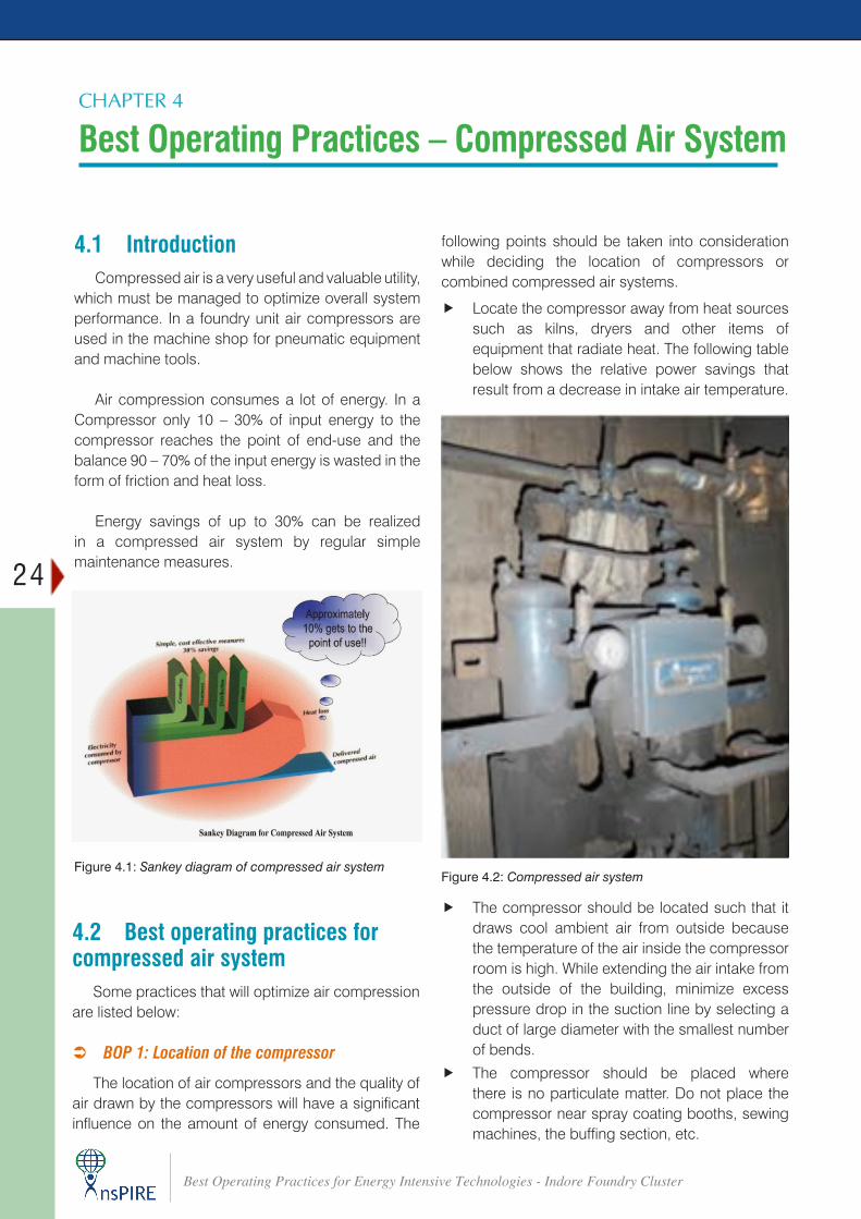
Air compression consumes a lot of energy. In a Compressor only 10 – 30% of input energy to the compressor reaches the point of end-use and the balance 90 – 70% of the input energy is wasted in the form of friction and heat loss.
Energy savings of up to 30% can be realized in a compressed air system by regular simple maintenance measures.
4.2 Best operating practices for compressed air system
Some practices that will optimize air compression are listed below:
 BOP 1: Location of the compressor
The location of air compressors and the quality of air drawn by the compressors will have a significant influence on the amount of energy consumed. The
following points should be taken into consideration while deciding the location of compressors or combined compressed air systems.
f Locate the compressor away from heat sources such as kilns, dryers and other items of equipment that radiate heat. The following table below shows the relative power savings that result from a decrease in intake air temperature.
Figure 4.1: Sankey diagram of compressed air systemFigure 4.2: Compressed air system
f The compressor should be located such that it draws cool ambient air from outside because the temperature of the air inside the compressor room is high. While extending the air intake from the outside of the building, minimize excess pressure drop in the suction line by selecting a duct of large diameter with the smallest number of bends.
f The compressor should be placed where there is no particulate matter. Do not place the compressor near spray coating booths, sewing machines, the buffing section, etc.
25
Best Operating Practices for Energy Intensive Technologies - Indore Foundry Cluster
f Any moisture in the inlet air to the compressor will affect its performance adversely. The compressor should be placed away from equipment which may add moisture to the atmosphere, for example, rinsing lines, cooling towers, dryer exhaust, etc. If the compressed air is moist the components of the compressed air system will corrode. Also, the specific power consumption will increase.
 BOP 2: Delivering air at the lowest practical pressure
f Operating Compressor at the minimum practical pressure at end uses, together with a corresponding reduction in compressor discharge pressure(s), will reduce the consumption of compressed air, the leakage rate, and the energy consumption.
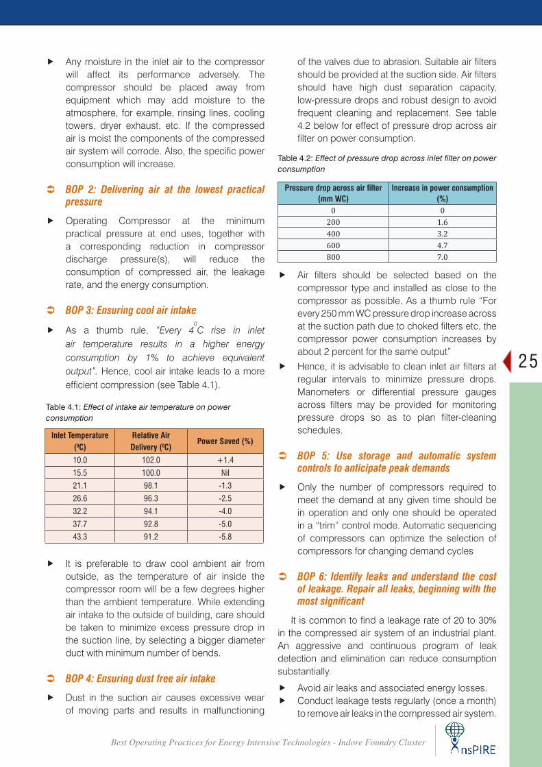
 BOP 3: Ensuring cool air intake
f As a thumb rule, “Every 40C rise in inlet
air temperature results in a higher energy consumption by 1% to achieve equivalent output”. Hence, cool air intake leads to a more efficient compression (see Table 4.1).
Inlet Temperature (0C)
Relative Air Delivery (0C)
Power Saved (%)
10.0 102.0 +1.4
15.5 100.0 Nil
21.1 98.1 -1.3
26.6 96.3 -2.5
32.2 94.1 -4.0
37.7 92.8 -5.0
43.3 91.2 -5.8
Table 4.1: Effect of intake air temperature on power consumption
Table 4.2: Effect of pressure drop across inlet filter on power consumption
Pressure drop across air filter (mm WC)
Increase in power consumption (%)
0 0200 1.6400 3.2600 4.7800 7.0
f It is preferable to draw cool ambient air from outside, as the temperature of air inside the compressor room will be a few degrees higher than the ambient temperature. While extending air intake to the outside of building, care should be taken to minimize excess pressure drop in the suction line, by selecting a bigger diameter duct with minimum number of bends.
 BOP 4: Ensuring dust free air intake
f Dust in the suction air causes excessive wear of moving parts and results in malfunctioning
of the valves due to abrasion. Suitable air filters should be provided at the suction side. Air filters should have high dust separation capacity, low-pressure drops and robust design to avoid frequent cleaning and replacement. See table 4.2 below for effect of pressure drop across air filter on power consumption.
f Air filters should be selected based on the compressor type and installed as close to the compressor as possible. As a thumb rule “For every 250 mm WC pressure drop increase across at the suction path due to choked filters etc, the compressor power consumption increases by about 2 percent for the same output”
f Hence, it is advisable to clean inlet air filters at regular intervals to minimize pressure drops. Manometers or differential pressure gauges across filters may be provided for monitoring pressure drops so as to plan filter-cleaning schedules.
 BOP 5: Use storage and automatic system controls to anticipate peak demands
f Only the number of compressors required to meet the demand at any given time should be in operation and only one should be operated in a “trim” control mode. Automatic sequencing of compressors can optimize the selection of compressors for changing demand cycles
 BOP 6: Identify leaks and understand the cost of leakage. Repair all leaks, beginning with the most significant
It is common to find a leakage rate of 20 to 30% in the compressed air system of an industrial plant. An aggressive and continuous program of leak detection and elimination can reduce consumption substantially.
f Avoid air leaks and associated energy losses. f Conduct leakage tests regularly (once a month)
to remove air leaks in the compressed air system.
26
Best Operating Practices for Energy Intensive Technologies - Indore Foundry Cluster
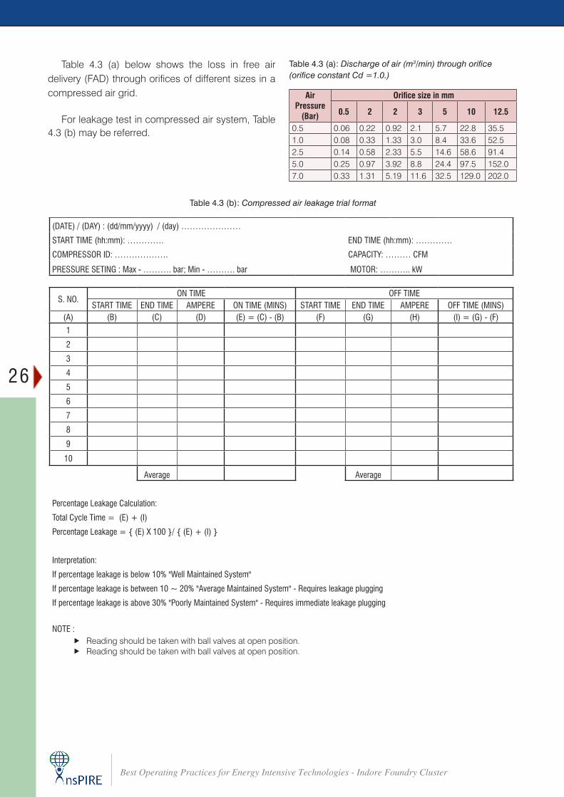
Table 4.3 (a) below shows the loss in free air delivery (FAD) through orifices of different sizes in a compressed air grid.
For leakage test in compressed air system, Table 4.3 (b) may be referred.
Table 4.3 (a): Discharge of air (m3/min) through orifice (orifice constant Cd =1.0.)
Air Pressure
(Bar)
Orifice size in mm
0.5 2 2 3 5 10 12.5
0.5 0.06 0.22 0.92 2.1 5.7 22.8 35.51.0 0.08 0.33 1.33 3.0 8.4 33.6 52.52.5 0.14 0.58 2.33 5.5 14.6 58.6 91.45.0 0.25 0.97 3.92 8.8 24.4 97.5 152.07.0 0.33 1.31 5.19 11.6 32.5 129.0 202.0
Table 4.3 (b): Compressed air leakage trial format
(DATE) / (DAY) : (dd/mm/yyyy) / (day) …………………
START TIME (hh:mm): …………. END TIME (hh:mm): ………….
COMPRESSOR ID: ………………. CAPACITY: ……… CFM
PRESSURE SETING : Max - ………. bar; Min - ………. bar MOTOR: ……….. kW
S. NO.ON TIME OFF TIME
START TIME END TIME AMPERE ON TIME (MINS) START TIME END TIME AMPERE OFF TIME (MINS)(A) (B) (C) (D) (E) = (C) - (B) (F) (G) (H) (I) = (G) - (F)
1
2
3
4
5
6
7
8
9
10
Average Average
Percentage Leakage Calculation:
Total Cycle Time = (E) + (I)
Percentage Leakage = { (E) X 100 }/ { (E) + (I) }
Interpretation:
If percentage leakage is below 10% "Well Maintained System"
If percentage leakage is between 10 ~ 20% "Average Maintained System" - Requires leakage plugging
If percentage leakage is above 30% "Poorly Maintained System" - Requires immediate leakage plugging
NOTE : f Reading should be taken with ball valves at open position. f Reading should be taken with ball valves at open position.
27
Best Operating Practices for Energy Intensive Technologies - Indore Foundry Cluster
 BOP 7: Make sure that compressed air is the best alternative for the application.
f Although compressed air can be a very versatile utility, not all applications are best served by it. The cost of compressed air often is overlooked because of the convenience and ergonomic advantages it provides. Many of the productivity improvements in automated manufacturing processes have been achieved through the appropriate use of compressed air.
f Determine the minimum practical pressure required for the application and use a blower, rather than a compressor, if appropriate.
 BOP 8: All parts of a process may not need air simultaneously.
f Analyze the peak and average rates of flow to determine actual needs and whether local secondary storage may be advantageous
 BOP 9: Turn off the compressed air supply at a process when it is not running.
f Stopping the supply of compressed air to applications not in operation can reduce the consumption of compressed air. This can be accomplished very easily by means of a properly sized solenoid valve in the air supply to each application.
 BOP 10: Determine the cost of compressed air for each machine or process.
f Accurate measurements of air consumption and electrical power allow proper assessment and appreciation of the true cost of operation. This, in turn, can help in management and conservation of available resources
 BOP 11: Compressor lubrication
f Use a synthetic lubricant if the compressor manufacturer permits it.
f Be sure lubricating oil temperature is not too high (oil degradation and lowered viscosity) and not too low (condensation contamination).
f Change the oil filter regularly. f Periodically inspect compressor intercoolers for
proper functioning.
 BOP 12: Minimize the pressure drop
f Minimize the pressure drop in the line between the point of generation and the point of use. Excess pressure drop can result from the following:
f Inadequate pipe size f Choked filter elements f Improperly sized couplings and hoses f All these lead to significant energy losses.
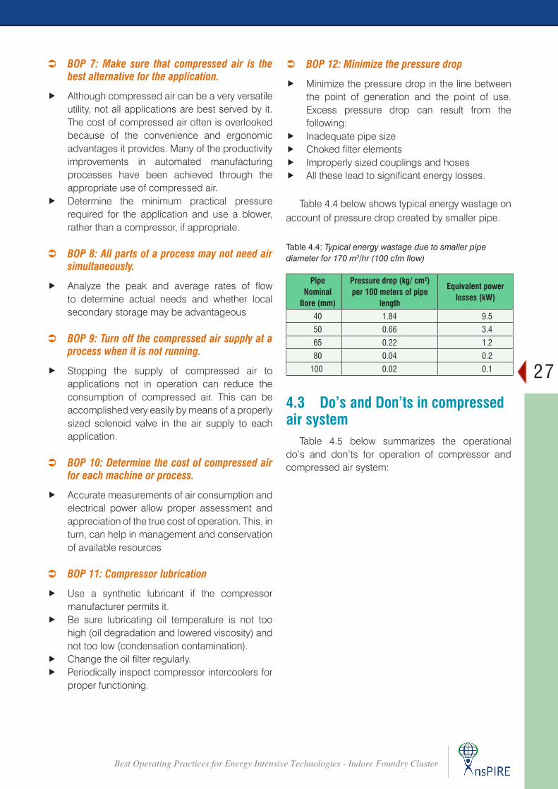
Table 4.4 below shows typical energy wastage on account of pressure drop created by smaller pipe.
Table 4.4: Typical energy wastage due to smaller pipe diameter for 170 m3/hr (100 cfm flow)
Pipe Nominal
Bore (mm)
Pressure drop (kg/ cm2) per 100 meters of pipe
length
Equivalent powerlosses (kW)
40 1.84 9.5
50 0.66 3.4
65 0.22 1.2
80 0.04 0.2
100 0.02 0.1
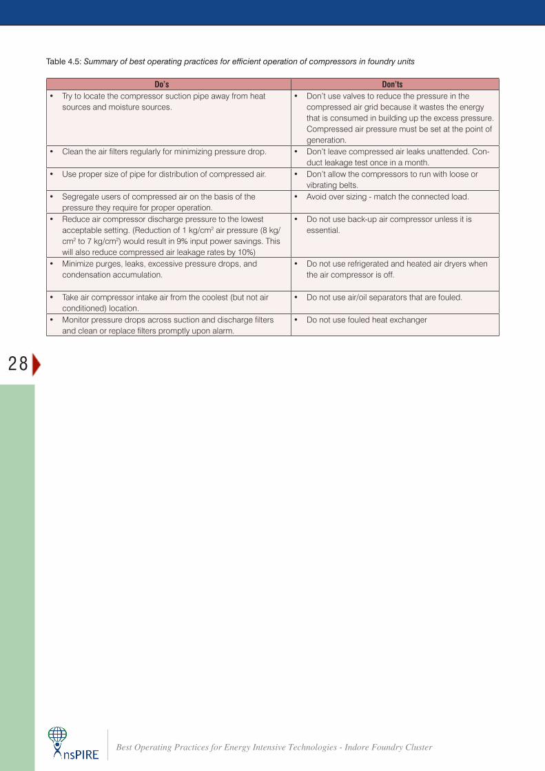
4.3 Do’s and Don’ts in compressed air system
Table 4.5 below summarizes the operational do’s and don’ts for operation of compressor and compressed air system:
28
Best Operating Practices for Energy Intensive Technologies - Indore Foundry Cluster
Table 4.5: Summary of best operating practices for efficient operation of compressors in foundry units
Do’s Don’ts• Try to locate the compressor suction pipe away from heat
sources and moisture sources.• Don’t use valves to reduce the pressure in the
compressed air grid because it wastes the energy that is consumed in building up the excess pressure. Compressed air pressure must be set at the point of generation.
• Clean the air filters regularly for minimizing pressure drop. • Don’t leave compressed air leaks unattended. Con-duct leakage test once in a month.
• Use proper size of pipe for distribution of compressed air. • Don’t allow the compressors to run with loose or vibrating belts.
• Segregate users of compressed air on the basis of the pressure they require for proper operation.
• Avoid over sizing - match the connected load.
• Reduce air compressor discharge pressure to the lowest acceptable setting. (Reduction of 1 kg/cm2 air pressure (8 kg/cm2 to 7 kg/cm2) would result in 9% input power savings. This will also reduce compressed air leakage rates by 10%)
• Do not use back-up air compressor unless it is essential.
• Minimize purges, leaks, excessive pressure drops, and condensation accumulation.
• Do not use refrigerated and heated air dryers when the air compressor is off.
• Take air compressor intake air from the coolest (but not air conditioned) location.
• Do not use air/oil separators that are fouled.
• Monitor pressure drops across suction and discharge filters and clean or replace filters promptly upon alarm.
• Do not use fouled heat exchanger
29
Best Operating Practices for Energy Intensive Technologies - Indore Foundry Cluster
Best Operating Practices – Motors and Pumps CHAPTER 5
A. Motor
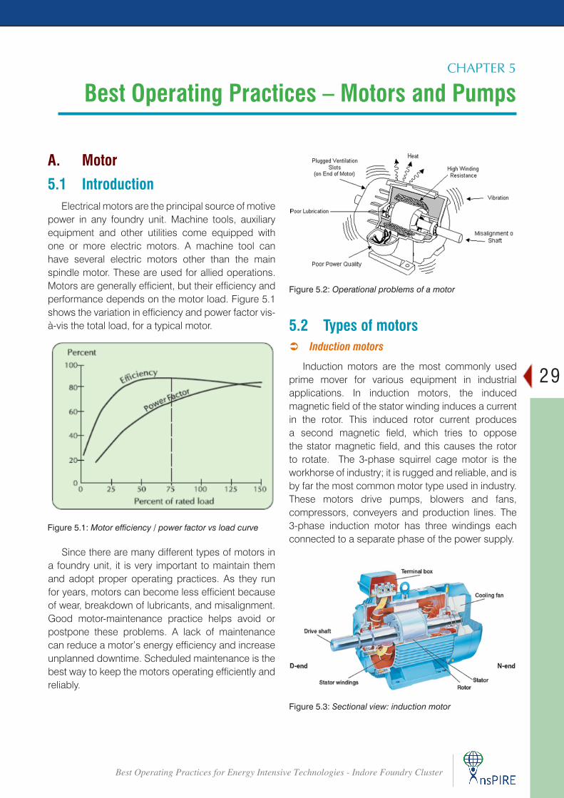
5.1 IntroductionElectrical motors are the principal source of motive
power in any foundry unit. Machine tools, auxiliary equipment and other utilities come equipped with one or more electric motors. A machine tool can have several electric motors other than the main spindle motor. These are used for allied operations. Motors are generally efficient, but their efficiency and performance depends on the motor load. Figure 5.1 shows the variation in efficiency and power factor vis-à-vis the total load, for a typical motor.
Figure 5.1: Motor efficiency / power factor vs load curve
Since there are many different types of motors in a foundry unit, it is very important to maintain them and adopt proper operating practices. As they run for years, motors can become less efficient because of wear, breakdown of lubricants, and misalignment. Good motor-maintenance practice helps avoid or postpone these problems. A lack of maintenance can reduce a motor’s energy efficiency and increase unplanned downtime. Scheduled maintenance is the best way to keep the motors operating efficiently and reliably.
Figure 5.2: Operational problems of a motor
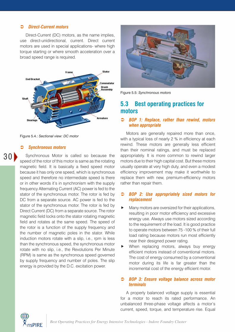
5.2 Types of motors  Induction motors
Induction motors are the most commonly used prime mover for various equipment in industrial applications. In induction motors, the induced magnetic field of the stator winding induces a current in the rotor. This induced rotor current produces a second magnetic field, which tries to oppose the stator magnetic field, and this causes the rotor to rotate. The 3-phase squirrel cage motor is the workhorse of industry; it is rugged and reliable, and is by far the most common motor type used in industry. These motors drive pumps, blowers and fans, compressors, conveyers and production lines. The 3-phase induction motor has three windings each connected to a separate phase of the power supply.
Figure 5.3: Sectional view: induction motor
30
Best Operating Practices for Energy Intensive Technologies - Indore Foundry Cluster
 Direct-Current motors
Direct-Current (DC) motors, as the name implies, use direct-unidirectional, current. Direct current motors are used in special applications- where high torque starting or where smooth acceleration over a broad speed range is required.
 Synchronous motors
Synchronous Motor is called so because the speed of the rotor of this motor is same as the rotating magnetic field. It is basically a fixed speed motor because it has only one speed, which is synchronous speed and therefore no intermediate speed is there or in other words it’s in synchronism with the supply frequency Alternating Current (AC) power is fed to the stator of the synchronous motor. The rotor is fed by DC from a separate source. AC power is fed to the stator of the synchronous motor. The rotor is fed by Direct Current (DC) from a separate source. The rotor magnetic field locks onto the stator rotating magnetic field and rotates at the same speed. The speed of the rotor is a function of the supply frequency and the number of magnetic poles in the stator. While induction motors rotate with a slip, i.e., rpm is less than the synchronous speed, the synchronous motor rotate with no slip, i.e., the Revolutions Per Minute (RPM) is same as the synchronous speed governed by supply frequency and number of poles. The slip energy is provided by the D.C. excitation power.
Figure 5.4.: Sectional view: DC motor
5.3 Best operating practices for motors
 BOP 1: Replace, rather than rewind, motors when appropriate
Motors are generally repaired more than once, with a typical loss of nearly 2 % in efficiency at each rewind. These motors are generally less efficient than their nominal ratings, and must be replaced appropriately. It is more common to rewind larger motors due to their high capital cost. But these motors usually operate at very high duty, and even a modest efficiency improvement may make it worthwhile to replace them with new, premium-efficiency motors rather than repair them.
 BOP 2: Use appropriately sized motors for replacement
f Many motors are oversized for their applications, resulting in poor motor efficiency and excessive energy use. Always use motors sized according to the requirement of the load. It is good practice to operate motors between 75 -100 % of their full load rating because motors run most efficiently near their designed power rating.
f When replacing motors, always buy energy efficient motors instead of conventional motors. The cost of energy consumed by a conventional motor during its life is far greater than the incremental cost of the energy efficient motor.
 BOP 3: Ensure voltage balance across motor terminals
A properly balanced voltage supply is essential for a motor to reach its rated performance. An unbalanced three-phase voltage affects a motor’s current, speed, torque, and temperature rise. Equal
Figure 5.5: Synchronous motors
31
Best Operating Practices for Energy Intensive Technologies - Indore Foundry Cluster
loads on all three phases of electric service help in assuring a voltage balance while minimizing voltage losses. The options that can be exercised to minimize voltage unbalance include:
f Balancing any single phase loads equally among all the three phases
f Segregating any single phase loads which disturb the load balance and feed them from a separate line / transformer
 BOP 4: Reducing under-loading
Probably the most common practice contributing to sub-optimal motor efficiency is that of under-loading. Under-loading results in lower efficiency and power factor, and higher-than-necessary first cost for the motor and related control equipment.
f Carefully evaluate the load that would determine the capacity of the motor to be selected.
f For motors, which consistently operate at loads below 40 % of rated capacity, an inexpensive and effective measure might be to operate in star mode. A change from the standard delta operation to star operation involves re-configuring the wiring of the three phases of power input at the terminal box
f Motor operation in the star mode is possible only for applications where the torque-to-speed requirement is lower at reduced load.
f For applications with high initial torque and low running torque needs, Del-Star starters are also available in market, which help in load following derating of electric motors after initial start-up.
 BOP 5: Regular up-keep
Properly selected and installed motors can operate for many years with minimal maintenance. Nonetheless, regular care will extend their life and maximize their energy efficiency. A list of such practices and measures is presented below.
f Clean motor surfaces and ventilation openings periodically. Heavy accumulations of dust and lint will result in overheating and premature motor failure.
f Properly lubricate moving parts to avoid unnecessary wear. Be sure to apply appropriate types and quantities of lubricant. Applying too little or too much can harm motor components.
f Keep motor couplings properly aligned. Correct shaft alignment ensures smooth, efficient transmission of power from the motor to the
load. Incorrect alignment puts strain on bearings and shafts, shortening their lives and reducing system efficiency.
f Check motor for over-heating and abnormal noises/sounds, sparking and ensure proper bedding of brushes.
f Tighten belts and pulleys to eliminate transmission losses.
 BOP 6: Install variable frequency drives
Motors frequently drive variable loads such as pumps, hydraulic systems and fans. In these applications, the motors’ efficiency is often poor because they are operated at low loads. It is appropriate to use a Variable Frequency Drive (VFD) with the motor.
 BOP 7: Install capacitor banks
Induction motors are characterized by power factors less than unity, leading to lower overall efficiency (and higher overall operating cost) associated with a plant’s electrical system.
f Install capacitors banks across motors with a high rating to reduce the distribution losses.
f Capacitors connected in parallel (shunted) with the motor are typically used to improve the power factor.
f The size of capacitor required for a particular motor depends upon the no-load reactive kVA (kVAR) drawn by the motor, which can be determined only from no-load testing of the motor. In general, the capacitor is selected to not exceed 90 % of the no-load kVAR of the motor. (Higher capacitors could result in over-voltages and motor burnouts)
Figure 5.6: Use of VFDs
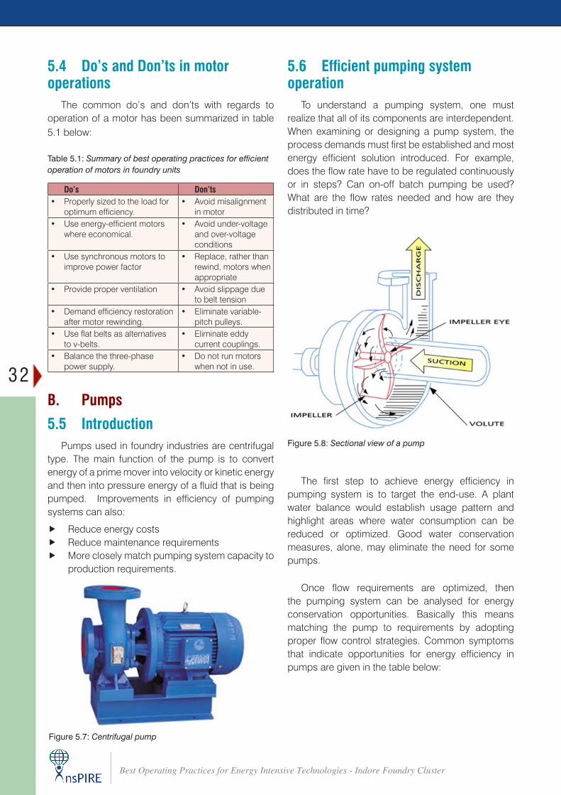
32
Best Operating Practices for Energy Intensive Technologies - Indore Foundry Cluster
5.4 Do’s and Don’ts in motor operations
The common do’s and don’ts with regards to operation of a motor has been summarized in table 5.1 below:
Table 5.1: Summary of best operating practices for efficient operation of motors in foundry units
Do’s Don’ts• Properly sized to the load for
optimum efficiency.• Avoid misalignment
in motor • Use energy-efficient motors
where economical.• Avoid under-voltage
and over-voltage conditions
• Use synchronous motors to improve power factor
• Replace, rather than rewind, motors when appropriate
• Provide proper ventilation • Avoid slippage due to belt tension
• Demand efficiency restoration after motor rewinding.
• Eliminate variable-pitch pulleys.
• Use flat belts as alternatives to v-belts.
• Eliminate eddy current couplings.
• Balance the three-phase power supply.
• Do not run motors when not in use.
B. Pumps
5.5 IntroductionPumps used in foundry industries are centrifugal
type. The main function of the pump is to convert energy of a prime mover into velocity or kinetic energy and then into pressure energy of a fluid that is being pumped. Improvements in efficiency of pumping systems can also:
f Reduce energy costs f Reduce maintenance requirements f More closely match pumping system capacity to
production requirements.
5.6 Efficient pumping system operation
To understand a pumping system, one must realize that all of its components are interdependent. When examining or designing a pump system, the process demands must first be established and most energy efficient solution introduced. For example, does the flow rate have to be regulated continuously or in steps? Can on-off batch pumping be used? What are the flow rates needed and how are they distributed in time?
Figure 5.7: Centrifugal pump
The first step to achieve energy efficiency in pumping system is to target the end-use. A plant water balance would establish usage pattern and highlight areas where water consumption can be reduced or optimized. Good water conservation measures, alone, may eliminate the need for some pumps.
Once flow requirements are optimized, then the pumping system can be analysed for energy conservation opportunities. Basically this means matching the pump to requirements by adopting proper flow control strategies. Common symptoms that indicate opportunities for energy efficiency in pumps are given in the table below:
Figure 5.8: Sectional view of a pump
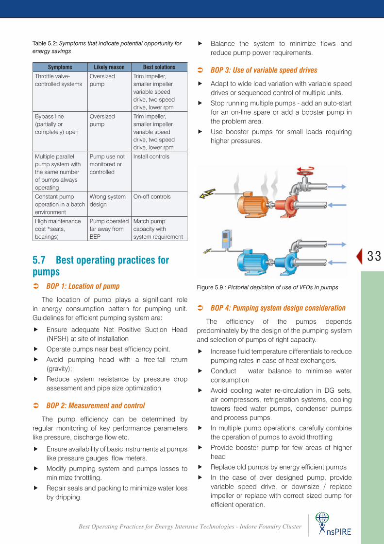
33
Best Operating Practices for Energy Intensive Technologies - Indore Foundry Cluster
Table 5.2: Symptoms that indicate potential opportunity for energy savings
Symptoms Likely reason Best solutions
Throttle valve-controlled systems
Oversized pump
Trim impeller, smaller impeller, variable speed drive, two speed drive, lower rpm
Bypass line (partially or completely) open
Oversized pump
Trim impeller, smaller impeller, variable speed drive, two speed drive, lower rpm
Multiple parallel pump system with the same number of pumps always operating
Pump use not monitored or controlled
Install controls
Constant pump operation in a batch environment
Wrong system design
On-off controls
High maintenance cost *seats, bearings)
Pump operated far away from BEP
Match pump capacity with system requirement
5.7 Best operating practices for pumps
 BOP 1: Location of pump
The location of pump plays a significant role in energy consumption pattern for pumping unit. Guidelines for efficient pumping system are:
f Ensure adequate Net Positive Suction Head (NPSH) at site of installation
f Operate pumps near best efficiency point.
f Avoid pumping head with a free-fall return (gravity);
f Reduce system resistance by pressure drop assessment and pipe size optimization
 BOP 2: Measurement and control
The pump efficiency can be determined by regular monitoring of key performance parameters like pressure, discharge flow etc.
f Ensure availability of basic instruments at pumps like pressure gauges, flow meters.
f Modify pumping system and pumps losses to minimize throttling.
f Repair seals and packing to minimize water loss by dripping.
f Balance the system to minimize flows and reduce pump power requirements.
 BOP 3: Use of variable speed drives
f Adapt to wide load variation with variable speed drives or sequenced control of multiple units.
f Stop running multiple pumps - add an auto-start for an on-line spare or add a booster pump in the problem area.
f Use booster pumps for small loads requiring higher pressures.
 BOP 4: Pumping system design consideration
The efficiency of the pumps depends predominately by the design of the pumping system and selection of pumps of right capacity.
f Increase fluid temperature differentials to reduce pumping rates in case of heat exchangers.
f Conduct water balance to minimise water consumption
f Avoid cooling water re-circulation in DG sets, air compressors, refrigeration systems, cooling towers feed water pumps, condenser pumps and process pumps.
f In multiple pump operations, carefully combine the operation of pumps to avoid throttling
f Provide booster pump for few areas of higher head
f Replace old pumps by energy efficient pumps
f In the case of over designed pump, provide variable speed drive, or downsize / replace impeller or replace with correct sized pump for efficient operation.
Figure 5.9.: Pictorial depiction of use of VFDs in pumps
34
Best Operating Practices for Energy Intensive Technologies - Indore Foundry Cluster
f Optimise number of stages in multi-stage pump in case of head margins
f Reduce demand on Pumping System: Demand on pumping system can be reduced by:
® Reducing consumption
® Reducing leaks
® Lowering pumping system flow rate
® Lowering the operating pressure
® Operating the system for a shorter period of time each day
® Having the system off when not needed.
5.8 Do’s and Don’ts in pump operation
The common dos and don’ts for efficient pumping operations are listed in Table 5.3 below:
Table 5.3: Summary of best operating practices for efficient operation of motors in foundry units
Do’s Don’ts
• Replace throttling valves with speed controls • Do not use inefficient pumps
• Reduce speed for fixed load • Avoid pumping head with a free return (gravity)
• Replace motor with a more efficient motors • Avoid water loss by dripping
• Ensure adequate NPSH at site of installation • Stop running multiple pumps - add an auto-start for an on-line spare or add a booster pump in the problem area.
• Provide metering of components (such as flows, kWh) • Avoid inadequate NPSH
• Operate pumps near best efficiency point • Do not run the system when not needed
• Use booster pumps for small loads requiring higher pressures
• Avoid over loading the pump system
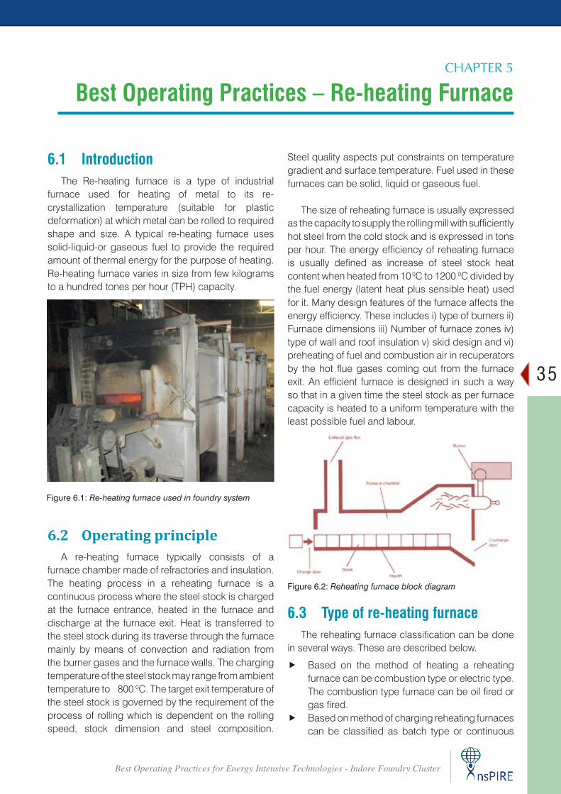
35
Best Operating Practices for Energy Intensive Technologies - Indore Foundry Cluster
Best Operating Practices – Re-heating Furnace CHAPTER 5
6.1 IntroductionThe Re-heating furnace is a type of industrial
furnace used for heating of metal to its re-crystallization temperature (suitable for plastic deformation) at which metal can be rolled to required shape and size. A typical re-heating furnace uses solid-liquid-or gaseous fuel to provide the required amount of thermal energy for the purpose of heating. Re-heating furnace varies in size from few kilograms to a hundred tones per hour (TPH) capacity.
Steel quality aspects put constraints on temperature gradient and surface temperature. Fuel used in these furnaces can be solid, liquid or gaseous fuel.
The size of reheating furnace is usually expressed as the capacity to supply the rolling mill with sufficiently hot steel from the cold stock and is expressed in tons per hour. The energy efficiency of reheating furnace is usually defined as increase of steel stock heat content when heated from 10 0C to 1200 0C divided by the fuel energy (latent heat plus sensible heat) used for it. Many design features of the furnace affects the energy efficiency. These includes i) type of burners ii) Furnace dimensions iii) Number of furnace zones iv) type of wall and roof insulation v) skid design and vi) preheating of fuel and combustion air in recuperators by the hot flue gases coming out from the furnace exit. An efficient furnace is designed in such a way so that in a given time the steel stock as per furnace capacity is heated to a uniform temperature with the least possible fuel and labour.
6.2 Operating principleA re-heating furnace typically consists of a
furnace chamber made of refractories and insulation. The heating process in a reheating furnace is a continuous process where the steel stock is charged at the furnace entrance, heated in the furnace and discharge at the furnace exit. Heat is transferred to the steel stock during its traverse through the furnace mainly by means of convection and radiation from the burner gases and the furnace walls. The charging temperature of the steel stock may range from ambient temperature to 800 0C. The target exit temperature of the steel stock is governed by the requirement of the process of rolling which is dependent on the rolling speed, stock dimension and steel composition.
Figure 6.1: Re-heating furnace used in foundry system
Figure 6.2: Reheating furnace block diagram
6.3 Type of re-heating furnaceThe reheating furnace classification can be done
in several ways. These are described below.
f Based on the method of heating a reheating furnace can be combustion type or electric type. The combustion type furnace can be oil fired or gas fired.
f Based on method of charging reheating furnaces can be classified as batch type or continuous
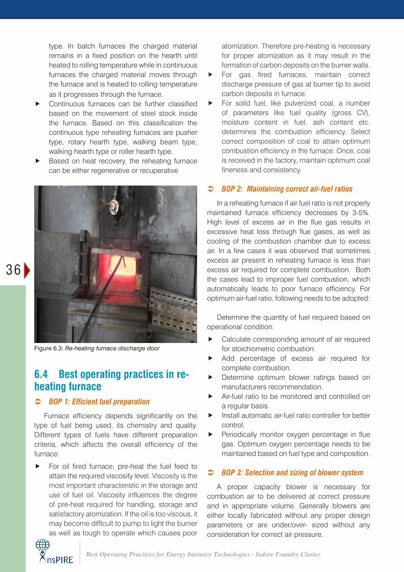
36
Best Operating Practices for Energy Intensive Technologies - Indore Foundry Cluster
type. In batch furnaces the charged material remains in a fixed position on the hearth until heated to rolling temperature while in continuous furnaces the charged material moves through the furnace and is heated to rolling temperature as it progresses through the furnace.
f Continuous furnaces can be further classified based on the movement of steel stock inside the furnace. Based on this classification the continuous type reheating furnaces are pusher type, rotary hearth type, walking beam type, walking hearth type or roller hearth type.
f Based on heat recovery, the reheating furnace can be either regenerative or recuperative
atomization. Therefore pre-heating is necessary for proper atomization as it may result in the formation of carbon deposits on the burner walls.
f For gas fired furnaces, maintain correct discharge pressure of gas at burner tip to avoid carbon deposits in furnace.
f For solid fuel, like pulverized coal, a number of parameters like fuel quality (gross CV), moisture content in fuel, ash content etc. determines the combustion efficiency. Select correct composition of coal to attain optimum combustion efficiency in the furnace. Once, coal is received in the factory, maintain optimum coal fineness and consistency.
 BOP 2: Maintaining correct air-fuel ratios
In a reheating furnace if air fuel ratio is not properly maintained furnace efficiency decreases by 3-5%. High level of excess air in the flue gas results in excessive heat loss through flue gases, as well as cooling of the combustion chamber due to excess air. In a few cases it was observed that sometimes excess air present in reheating furnace is less than excess air required for complete combustion. Both the cases lead to improper fuel combustion, which automatically leads to poor furnace efficiency. For optimum air-fuel ratio, following needs to be adopted:
Determine the quantity of fuel required based on operational condition.
f Calculate corresponding amount of air required for stoichiometric combustion.
f Add percentage of excess air required for complete combustion.
f Determine optimum blower ratings based on manufacturers recommendation.
f Air-fuel ratio to be monitored and controlled on a regular basis.
f Install automatic air-fuel ratio controller for better control.
f Periodically monitor oxygen percentage in flue gas. Optimum oxygen percentage needs to be maintained based on fuel type and composition.
 BOP 3: Selection and sizing of blower system
A proper capacity blower is necessary for combustion air to be delivered at correct pressure and in appropriate volume. Generally blowers are either locally fabricated without any proper design parameters or are under/over- sized without any consideration for correct air pressure.
6.4 Best operating practices in re-heating furnace
 BOP 1: Efficient fuel preparation
Furnace efficiency depends significantly on the type of fuel being used, its chemistry and quality. Different types of fuels have different preparation criteria, which affects the overall efficiency of the furnace:
f For oil fired furnace, pre-heat the fuel feed to attain the required viscosity level. Viscosity is the most important characteristic in the storage and use of fuel oil. Viscosity influences the degree of pre-heat required for handling, storage and satisfactory atomization. If the oil is too viscous, it may become difficult to pump to light the burner as well as tough to operate which causes poor
Figure 6.3: Re-heating furnace discharge door
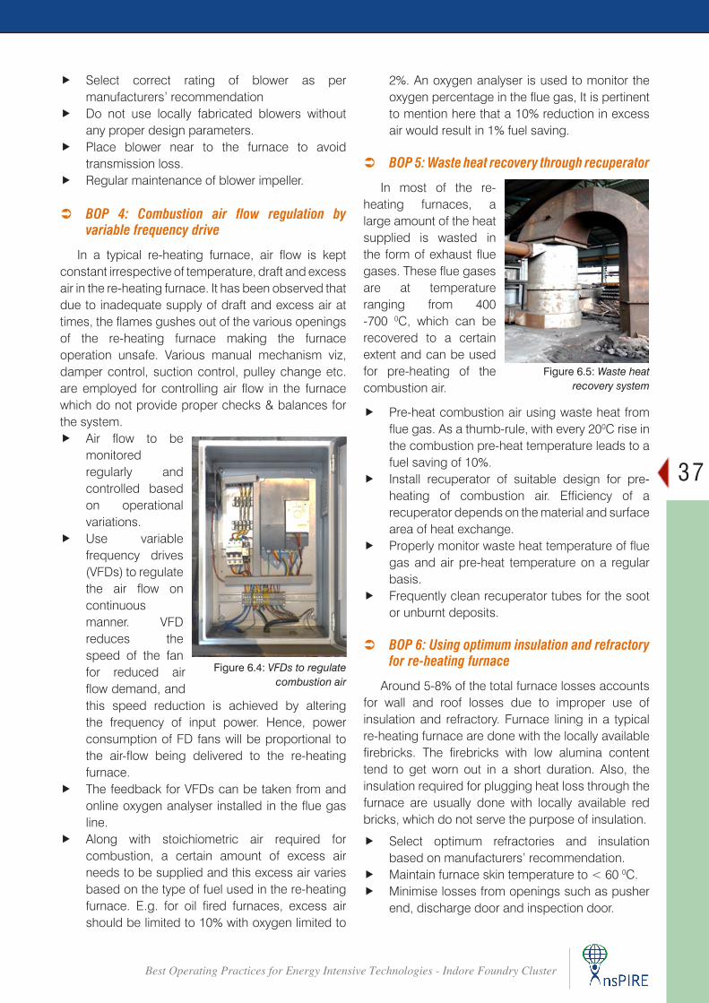
37
Best Operating Practices for Energy Intensive Technologies - Indore Foundry Cluster
f Select correct rating of blower as per manufacturers’ recommendation
f Do not use locally fabricated blowers without any proper design parameters.
f Place blower near to the furnace to avoid transmission loss.
f Regular maintenance of blower impeller.
 BOP 4: Combustion air flow regulation by variable frequency drive
In a typical re-heating furnace, air flow is kept constant irrespective of temperature, draft and excess air in the re-heating furnace. It has been observed that due to inadequate supply of draft and excess air at times, the flames gushes out of the various openings of the re-heating furnace making the furnace operation unsafe. Various manual mechanism viz, damper control, suction control, pulley change etc. are employed for controlling air flow in the furnace which do not provide proper checks & balances for the system.
f Air flow to be monitored regularly and controlled based on operational variations.
f Use variable frequency drives (VFDs) to regulate the air flow on continuous manner. VFD reduces the speed of the fan for reduced air flow demand, and
2%. An oxygen analyser is used to monitor the oxygen percentage in the flue gas, It is pertinent to mention here that a 10% reduction in excess air would result in 1% fuel saving.
 BOP 5: Waste heat recovery through recuperator
In most of the re-heating furnaces, a large amount of the heat supplied is wasted in the form of exhaust flue gases. These flue gases are at temperature ranging from 400 -700 0C, which can be recovered to a certain extent and can be used for pre-heating of the combustion air.
f Pre-heat combustion air using waste heat from flue gas. As a thumb-rule, with every 200C rise in the combustion pre-heat temperature leads to a fuel saving of 10%.
f Install recuperator of suitable design for pre-heating of combustion air. Efficiency of a recuperator depends on the material and surface area of heat exchange.
f Properly monitor waste heat temperature of flue gas and air pre-heat temperature on a regular basis.
f Frequently clean recuperator tubes for the soot or unburnt deposits.
 BOP 6: Using optimum insulation and refractory for re-heating furnace
Around 5-8% of the total furnace losses accounts for wall and roof losses due to improper use of insulation and refractory. Furnace lining in a typical re-heating furnace are done with the locally available firebricks. The firebricks with low alumina content tend to get worn out in a short duration. Also, the insulation required for plugging heat loss through the furnace are usually done with locally available red bricks, which do not serve the purpose of insulation.
f Select optimum refractories and insulation based on manufacturers’ recommendation.
f Maintain furnace skin temperature to < 60 0C. f Minimise losses from openings such as pusher
end, discharge door and inspection door.
Figure 6.4: VFDs to regulate combustion air
this speed reduction is achieved by altering the frequency of input power. Hence, power consumption of FD fans will be proportional to the air-flow being delivered to the re-heating furnace.
f The feedback for VFDs can be taken from and online oxygen analyser installed in the flue gas line.
f Along with stoichiometric air required for combustion, a certain amount of excess air needs to be supplied and this excess air varies based on the type of fuel used in the re-heating furnace. E.g. for oil fired furnaces, excess air should be limited to 10% with oxygen limited to
Figure 6.5: Waste heat recovery system
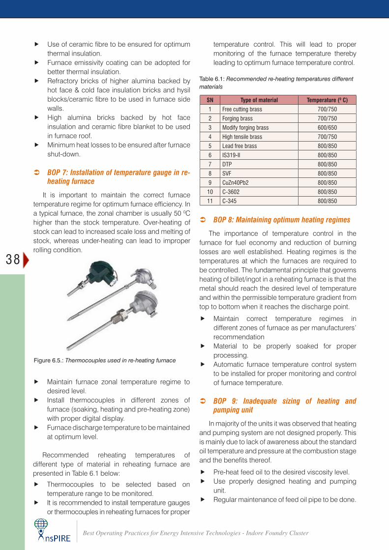
38
Best Operating Practices for Energy Intensive Technologies - Indore Foundry Cluster
f Use of ceramic fibre to be ensured for optimum thermal insulation.
f Furnace emissivity coating can be adopted for better thermal insulation.
f Refractory bricks of higher alumina backed by hot face & cold face insulation bricks and hysil blocks/ceramic fibre to be used in furnace side walls.
f High alumina bricks backed by hot face insulation and ceramic fibre blanket to be used in furnace roof.
f Minimum heat losses to be ensured after furnace shut-down.
 BOP 7: Installation of temperature gauge in re-
heating furnace
It is important to maintain the correct furnace temperature regime for optimum furnace efficiency. In a typical furnace, the zonal chamber is usually 50 0C higher than the stock temperature. Over-heating of stock can lead to increased scale loss and melting of stock, whereas under-heating can lead to improper rolling condition.
Figure 6.5.: Thermocouples used in re-heating furnace
temperature control. This will lead to proper monitoring of the furnace temperature thereby leading to optimum furnace temperature control.
Table 6.1: Recommended re-heating temperatures different materials
SN Type of material Temperature (0 C)
1 Free cutting brass 700/750
2 Forging brass 700/750
3 Modify forging brass 600/650
4 High tensile brass 700/750
5 Lead free brass 800/850
6 IS319-II 800/850
7 DTP 800/850
8 SVF 800/850
9 CuZn40Pb2 800/850
10 C-3602 800/850
11 C-345 800/850
f Maintain furnace zonal temperature regime to desired level.
f Install thermocouples in different zones of furnace (soaking, heating and pre-heating zone) with proper digital display.
f Furnace discharge temperature to be maintained at optimum level.
Recommended reheating temperatures of different type of material in reheating furnace are presented in Table 6.1 below:
f Thermocouples to be selected based on temperature range to be monitored.
f It is recommended to install temperature gauges or thermocouples in reheating furnaces for proper
 BOP 8: Maintaining optimum heating regimes
The importance of temperature control in the furnace for fuel economy and reduction of burning losses are well established. Heating regimes is the temperatures at which the furnaces are required to be controlled. The fundamental principle that governs heating of billet/ingot in a reheating furnace is that the metal should reach the desired level of temperature and within the permissible temperature gradient from top to bottom when it reaches the discharge point.
f Maintain correct temperature regimes in different zones of furnace as per manufacturers’ recommendation
f Material to be properly soaked for proper processing.
f Automatic furnace temperature control system to be installed for proper monitoring and control of furnace temperature.
 BOP 9: Inadequate sizing of heating and pumping unit
In majority of the units it was observed that heating and pumping system are not designed properly. This is mainly due to lack of awareness about the standard oil temperature and pressure at the combustion stage and the benefits thereof.
f Pre-heat feed oil to the desired viscosity level. f Use properly designed heating and pumping
unit. f Regular maintenance of feed oil pipe to be done.
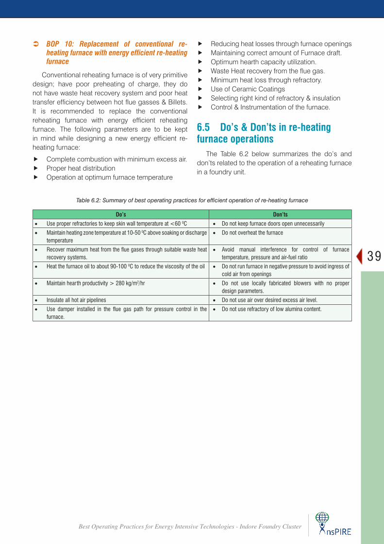
39
Best Operating Practices for Energy Intensive Technologies - Indore Foundry Cluster
 BOP 10: Replacement of conventional re-heating furnace with energy efficient re-heating furnace
Conventional reheating furnace is of very primitive design; have poor preheating of charge, they do not have waste heat recovery system and poor heat transfer efficiency between hot flue gasses & Billets. It is recommended to replace the conventional reheating furnace with energy efficient reheating furnace. The following parameters are to be kept in mind while designing a new energy efficient re-heating furnace:
f Complete combustion with minimum excess air. f Proper heat distribution f Operation at optimum furnace temperature
Table 6.2: Summary of best operating practices for efficient operation of re-heating furnace
Do’s Don’ts
• Use proper refractories to keep skin wall temperature at <60 0C • Do not keep furnace doors open unnecessarily
• Maintain heating zone temperature at 10-50 0C above soaking or discharge temperature
• Do not overheat the furnace
• Recovermaximumheatfromthefluegasesthroughsuitablewasteheatrecovery systems.
• Avoid manual interference for control of furnace temperature, pressure and air-fuel ratio
• Heat the furnace oil to about 90-100 0C to reduce the viscosity of the oil • Do not run furnace in negative pressure to avoid ingress of cold air from openings
• Maintain hearth productivity > 280 kg/m2/hr • Do not use locally fabricated blowers with no proper design parameters.
• Insulate all hot air pipelines • Do not use air over desired excess air level.
• Use damper installed in the flue gas path for pressure control in thefurnace.
• Do not use refractory of low alumina content.
f Reducing heat losses through furnace openings f Maintaining correct amount of Furnace draft. f Optimum hearth capacity utilization. f Waste Heat recovery from the flue gas. f Minimum heat loss through refractory. f Use of Ceramic Coatings f Selecting right kind of refractory & insulation f Control & Instrumentation of the furnace.
6.5 Do’s & Don’ts in re-heating furnace operations
The Table 6.2 below summarizes the do’s and don’ts related to the operation of a reheating furnace in a foundry unit.
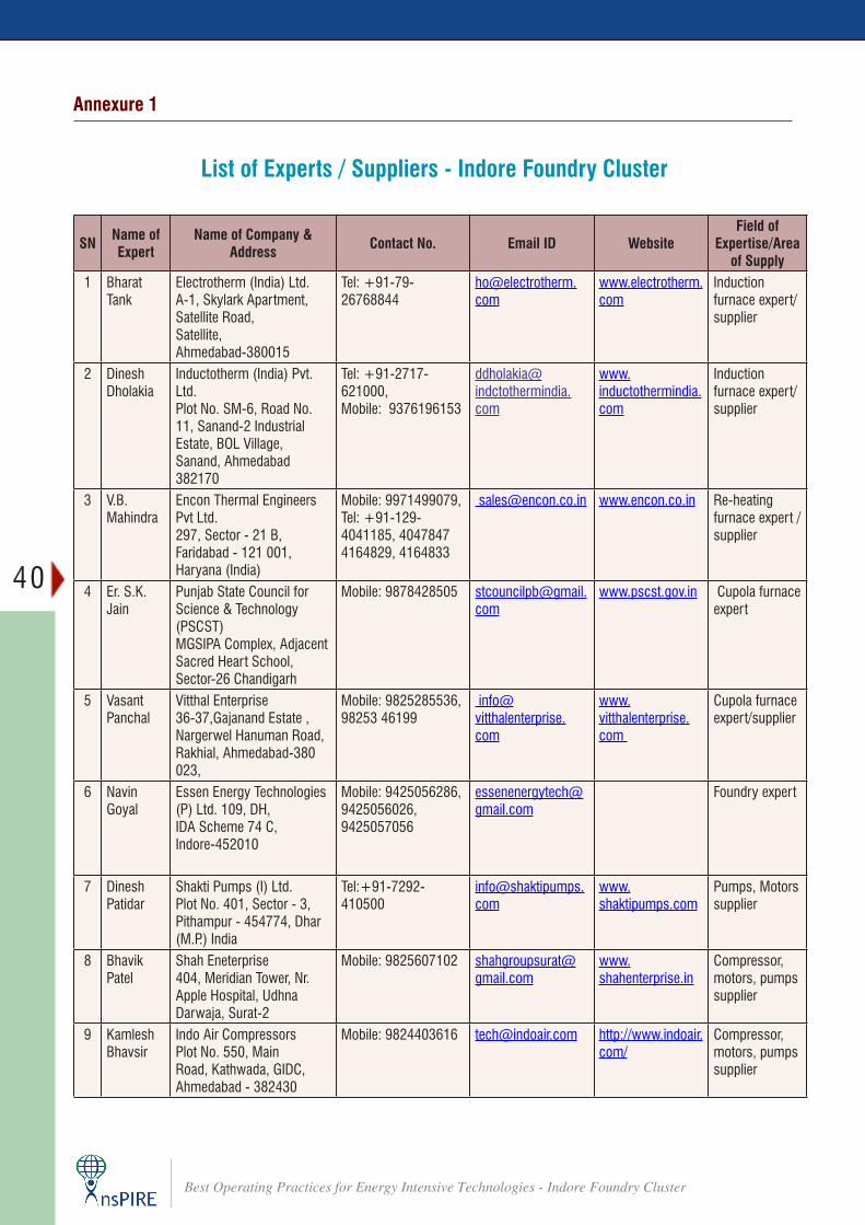
40
Best Operating Practices for Energy Intensive Technologies - Indore Foundry Cluster
Annexure 1
List of Experts / Suppliers - Indore Foundry Cluster
SN Name of Expert
Name of Company & Address Contact No. Email ID Website
Field of Expertise/Area
of Supply1 Bharat
TankElectrotherm (India) Ltd. A-1, Skylark Apartment,Satellite Road,Satellite, Ahmedabad-380015
Tel: +91-79-26768844
www.electrotherm.com
Induction furnace expert/supplier
2 Dinesh Dholakia
Inductotherm (India) Pvt. Ltd.Plot No. SM-6, Road No. 11, Sanand-2 Industrial Estate, BOL Village, Sanand, Ahmedabad 382170
Tel: +91-2717-621000, Mobile: 9376196153
www.inductothermindia.com
Induction furnace expert/supplier
3 V.B. Mahindra
Encon Thermal Engineers Pvt Ltd.297, Sector - 21 B, Faridabad - 121 001, Haryana (India)
Mobile: 9971499079, Tel: +91-129-4041185, 4047847 4164829, 4164833
[email protected] www.encon.co.in Re-heating furnace expert / supplier
4 Er. S.K. Jain
Punjab State Council for Science & Technology (PSCST)MGSIPA Complex, Adjacent Sacred Heart School, Sector-26 Chandigarh
Mobile: 9878428505 [email protected]
www.pscst.gov.in Cupola furnace expert
5 Vasant Panchal
Vitthal Enterprise36-37,Gajanand Estate , Nargerwel Hanuman Road, Rakhial, Ahmedabad-380 023,
Mobile: 9825285536, 98253 46199
www.vitthalenterprise.com
Cupola furnace expert/supplier
6 Navin Goyal
Essen Energy Technologies (P) Ltd. 109, DH, IDA Scheme 74 C, Indore-452010
Mobile: 9425056286, 9425056026, 9425057056
Foundry expert
7 Dinesh Patidar
Shakti Pumps (I) Ltd.Plot No. 401, Sector - 3, Pithampur - 454774, Dhar (M.P.) India
Tel:+91-7292-410500
www.shaktipumps.com
Pumps, Motors supplier
8 Bhavik Patel
Shah Eneterprise 404, Meridian Tower, Nr. Apple Hospital, Udhna Darwaja, Surat-2
Mobile: 9825607102 [email protected]
www.shahenterprise.in
Compressor, motors, pumps supplier
9 Kamlesh Bhavsir
Indo Air CompressorsPlot No. 550, Main Road, Kathwada, GIDC, Ahmedabad - 382430
Mobile: 9824403616 [email protected] http://www.indoair.com/
Compressor, motors, pumps supplier

41
Best Operating Practices for Energy Intensive Technologies - Indore Foundry Cluster
For details, contact:
BEE-UNIDO PMU4th Floor, Sewa Bhawan
R. K. Puram, New Delhi - 110066 (INDIA) Tel: +91-11-2617-9699Fax: +91-11-2617-8352