Embed Size (px)
Citation preview
No part of this book may be reproduced or transmitted in any form or by any means, C.D. ROM/Audio Video Cassettes or electronic, mechanicalincluding photocopying; recording or by any information storage and retrieval system without permission in writing from the Publisher.
First Year Diploma Semester - II
PREFACE
Elements of ElectronicsElectronics Engineering Group
Printed at: Repro Knowledgecast Ltd., Mumbai
TEID : 971
Written as per the revised ‘G’ Scheme syllabus prescribed by the Maharashtra State Board of Technical Education (MSBTE) w.e.f. academic year 2012-2013
First Edition: November 2015
Salient Features
• Concise content with complete coverage of revised G-scheme syllabus. • Simple and Lucid language.
• Neat, Labelled and Authentic diagrams.
• Illustrative examples showing detailed solution of numericals.
• MSBTE Theory Questions and Numericals from Summer-2007 to Winter-2015.
• Includes MSBTE Question Papers of Summer, Winter - 2014 and 2015. • Three Model Question Papers for practice.
• Important Inclusions: Additional Theory Questions, Practice Problems, KnowledgeBank.
PREFACE Target’s “Elements of Electronics” is compiled with an aim of shaping engineering minds of students while catering to their needs. It is a complete & thorough book designed as per the new revised G-scheme of MSBTE curriculum effective from June 2012. Each unit from the syllabus is divided into chapters bearing ‘specific objectives’ in mind. The sub-topic wise classification of this book helps the students in easy comprehension. Each chapter includes the following features: Theory is provided in the form of pointers. Neat labelled diagrams have been provided wherever
required. Italicized definitions are hard to miss and help students map answers easily. Illustrative Examples are provided in order to understand the application of different concepts and
formulae. By introducing them after formulae, these examples enable students to gain command over formulae. An array of problems from simple to complex are included. (Examples here are similar to problems asked in previous years’ MSBTE Question Papers and also problems important from examination point of view)
Formulae are provided for quick recap and last minute revision. MSBTE Theory Questions covered in separate section to give a clear idea of the type of questions
asked. (Reference of answer to each question is provided.) MSBTE Numericals till latest year are included with complete solutions. MSBTE Waveform Questions offer conceptual solutions to waveform based question. Additional Theory Questions help students to gain insight on the various levels of theory-based
questions. Problems for Practice (With final answers) covers a variety of questions from simple to complex. Knowledge Bank is designed to enrich students by providing the knowledge required to understand
the concept covered in syllabus but does not fall in the scope of syllabus. MSBTE Question Papers of years 2014 and 2015 are added at the end to make students familiar with the MSBTE examination pattern. A set of three Model Question Papers is designed as per MSBTE Pattern for thorough revision and to prepare the students for the final examination.
Best of luck to all the aspirants! From, Publisher
SYLLABUS
Topic and Contents Hours Marks
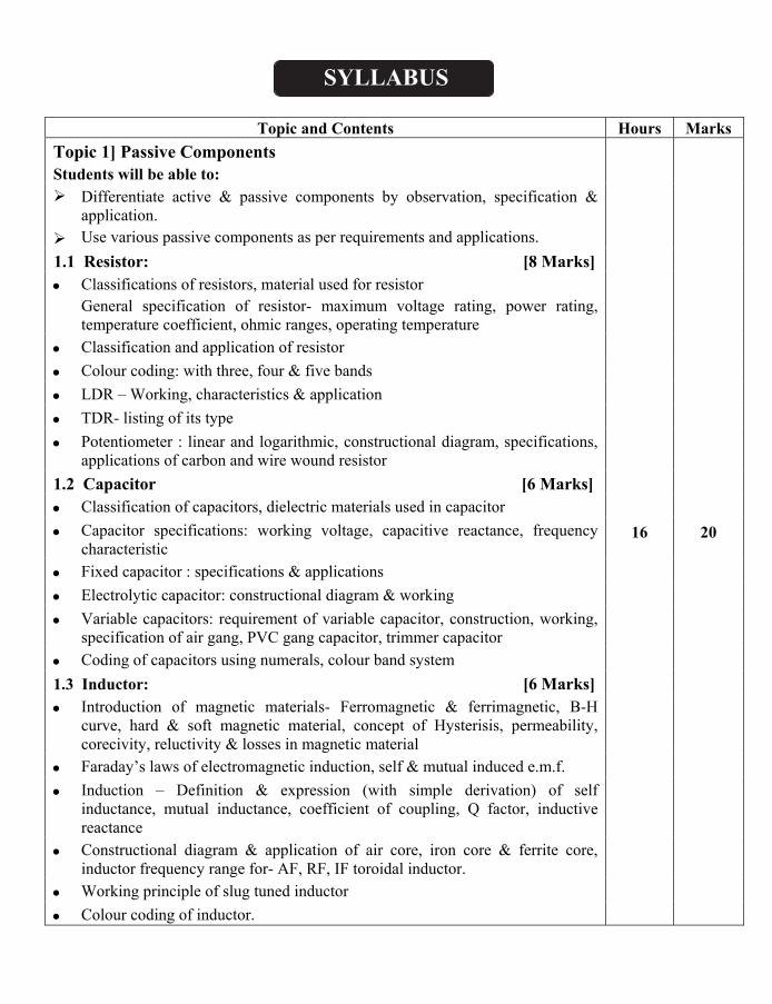
Topic 1] Passive Components Students will be able to:
16 20
Differentiate active & passive components by observation, specification & application. Use various passive components as per requirements and applications.
1.1 Resistor: [8 Marks]
Classifications of resistors, material used for resistor General specification of resistor- maximum voltage rating, power rating, temperature coefficient, ohmic ranges, operating temperature
Classification and application of resistor
Colour coding: with three, four & five bands
LDR – Working, characteristics & application
TDR- listing of its type
Potentiometer : linear and logarithmic, constructional diagram, specifications, applications of carbon and wire wound resistor
1.2 Capacitor [6 Marks]
Classification of capacitors, dielectric materials used in capacitor
Capacitor specifications: working voltage, capacitive reactance, frequency characteristic
Fixed capacitor : specifications & applications
Electrolytic capacitor: constructional diagram & working
Variable capacitors: requirement of variable capacitor, construction, working, specification of air gang, PVC gang capacitor, trimmer capacitor
Coding of capacitors using numerals, colour band system
1.3 Inductor: [6 Marks]
Introduction of magnetic materials- Ferromagnetic & ferrimagnetic, B-H curve, hard & soft magnetic material, concept of Hysterisis, permeability, corecivity, reluctivity & losses in magnetic material
Faraday’s laws of electromagnetic induction, self & mutual induced e.m.f.
Induction – Definition & expression (with simple derivation) of self inductance, mutual inductance, coefficient of coupling, Q factor, inductive reactance
Constructional diagram & application of air core, iron core & ferrite core, inductor frequency range for- AF, RF, IF toroidal inductor.
Working principle of slug tuned inductor
Colour coding of inductor.
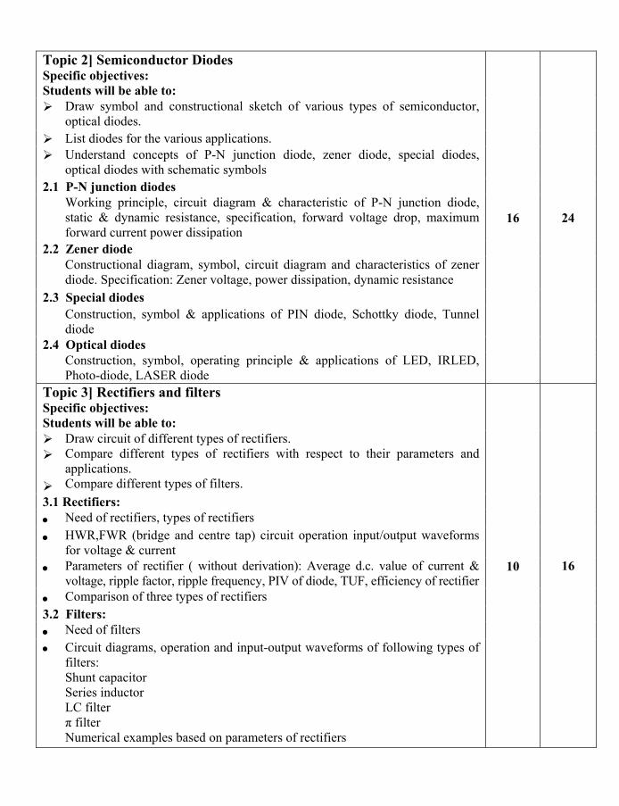
Topic 2] Semiconductor Diodes Specific objectives: Students will be able to:
16 24
Draw symbol and constructional sketch of various types of semiconductor, optical diodes.
List diodes for the various applications.
Understand concepts of P-N junction diode, zener diode, special diodes, optical diodes with schematic symbols
2.1 P-N junction diodes Working principle, circuit diagram & characteristic of P-N junction diode,
static & dynamic resistance, specification, forward voltage drop, maximum forward current power dissipation
2.2 Zener diode Constructional diagram, symbol, circuit diagram and characteristics of zener
diode. Specification: Zener voltage, power dissipation, dynamic resistance 2.3 Special diodes Construction, symbol & applications of PIN diode, Schottky diode, Tunnel
diode 2.4 Optical diodes Construction, symbol, operating principle & applications of LED, IRLED,
Photo-diode, LASER diode Topic 3] Rectifiers and filters Specific objectives: Students will be able to:
10 16
Draw circuit of different types of rectifiers. Compare different types of rectifiers with respect to their parameters and applications. Compare different types of filters.
3.1 Rectifiers: Need of rectifiers, types of rectifiers
HWR,FWR (bridge and centre tap) circuit operation input/output waveforms for voltage & current
Parameters of rectifier ( without derivation): Average d.c. value of current & voltage, ripple factor, ripple frequency, PIV of diode, TUF, efficiency of rectifier
Comparison of three types of rectifiers 3.2 Filters: Need of filters
Circuit diagrams, operation and input-output waveforms of following types of filters: Shunt capacitor Series inductor LC filter π filter Numerical examples based on parameters of rectifiers
Topic 4] Wave shaping circuit Specific objectives: Students will be able to:
08 16
Draw circuit of different types of wave shaping circuits. Compare different types of wave shaping circuits with respect to the parameters and applications.
4.1 Linear wave shaping circuit Need of wave shaping circuits, comparison between linear and non-linear
wave shaping circuits Operations of wave shaping circuits Linear circuits: RC integrator & differentiator 4.2 Non-linear wave shaping circuits Circuit diagram, operation, waveforms of different types of clippers using
diodes: series, shunt, (biased and unbiased) Circuit diagram, operation, waveforms of different types of clampers: positive
and negative
Topic 5 – D.C. circuits and Network Theorems Specific objectives: Students will be able to:
14 24
Use basic rules of electrical circuits with the view of solving problems on electrical circuits.
Use various theorems to determine unknown electrical quantities in the network
5.1 Fundamentals of D.C. circuit Review of Ohm’s law Concept of open &short circuit Kirchhoff’s current and voltage law Maxwell’s loop current method 5.2 Node analysis
Concept of ideal & practical current and voltage sources, source conversion Star/Delta & Delta /Star conversion (no derivations) Network terminology- active, passive, linear, non-linear bilateral, unilateral
network 5.3 Network theorem: Statement, explanation & applications of following Superposition theorem Thevenin’s theorem Norton’s theorem
Maximum power transfer theorem Numerical examples on above topic.
TOTAL 64 100

Contents
Chapter No. Topic Page No.
Unit - I: Passive Components
1 Resistors 1
2 Capacitors 26
3 Inductors 48
Unit - II: Semiconductor Diodes
4 Semiconductor Diodes 77
Unit - III: Rectifiers and Filters
5 Rectifiers 111
6 Filters 139
Unit - IV: Wave Shaping Circuits
7 Wave Shaping Circuits 163
Unit - V: D.C. Circuits and Network Theorems
8 D.C. Circuits and Node Analysis 192
9 Network Theorems 218
Model Question Papers
Model Question Paper I 262
Model Question Paper II 265
Model Question Paper III 268
MSBTE Question Papers
Question Paper – Summer 2014 271
Question Paper – Winter 2014 274
Question Paper – Summer 2015 277
Question Paper – Winter 2015 280
Basic Physics (F.Y.Dip.Sem.-1) MSBTEChapter 01: Resistors
1
Publications Pvt. Ltd. Target
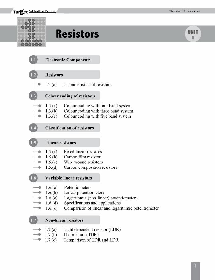
1.1 Electronic Components
1.5 Linear resistors
1.5.(a) Fixed linear resistors 1.5.(b) Carbon film resistor 1.5.(c) Wire wound resistors 1.5.(d) Carbon composition resistors
1.3.(a) Colour coding with four band system1.3.(b) Colour coding with three band system1.3.(c) Colour coding with five band system
1.7 Non-linear resistors
1.7.(a) Light dependent resistor (LDR)1.7.(b) Thermistors (TDR) 1.7.(c) Comparison of TDR and LDR
1.3 Colour coding of resistors
1.6.(a) Potentiometers 1.6.(b) Linear potentiometers 1.6.(c) Logarithmic (non-linear) potentiometers 1.6.(d) Specifications and applications 1.6.(e) Comparison of linear and logarithmic potentiometer
1.2.(a) Characteristics of resistors
1.4 Classification of resistors
1.2 Resistors
1.6 Variable linear resistors
Resistors UNIT I
2
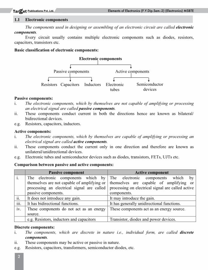
Elements of Electronics (F.Y.Dip.Sem.-2) (Electronics) MSBTEPublications Pvt. Ltd. Target 1.1 Electronic components The components used in designing or assembling of an electronic circuit are called electronic components. Every circuit usually contains multiple electronic components such as diodes, resistors, capacitors, transistors etc. Basic classification of electronic components: Passive components: i. The electronic components, which by themselves are not capable of amplifying or processing
an electrical signal are called passive components. ii. These components conduct current in both the directions hence are known as bilateral/
bidirectional devices. e.g. Resistors, capacitors, inductors. Active components: i. The electronic components, which by themselves are capable of amplifying or processing an
electrical signal are called active components. ii. These components conduct the current only in one direction and therefore are known as
unilateral/unidirectional devices. e.g. Electronic tubes and semiconductor devices such as diodes, transistors, FETs, UJTs etc. Comparison between passive and active components:
Passive component Active component i. The electronic components which by
themselves are not capable of amplifying or processing an electrical signal are called passive components.
The electronic components which by themselves are capable of amplifying or processing on electrical signal are called active components.
ii. It does not introduce any gain. It may introduce the gain. iii. It has bidirectional functions. It has generally unidirectional functions. iv. These components do not act as an energy
source. These components act as an energy source.
e.g. Resistors, inductors and capacitors Transistor, diodes and power devices. Discrete components: i. The components, which are discrete in nature i.e., individual form, are called discrete
components. ii. These components may be active or passive in nature. e.g. Resistors, capacitors, transformers, semiconductor diodes, etc.
Electronic components
Active componentsPassive components
Resistors Capacitors Inductors Electronictubes
Semiconductordevices
Basic Physics (F.Y.Dip.Sem.-1) MSBTEChapter 01: Resistors
3
Publications Pvt. Ltd. Target Non-discrete components: i. The components which are connected together to build a single circuit and not discrete in
nature are called non-discrete components. ii. These may be active or passive components. iii. Combination of non-discrete components form integrated circuits. Parasitic components: i. The components do not exist physically, but are due to electrodes or wirings are called
parasitic components. ii. Conceptually, they are present in the device and in the electronic circuits. iii. These components play an important role when circuit is operated at high frequency. e.g. Inter electrode capacitances, junction capacitances, stray capacitance, charge storage
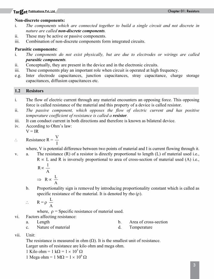
capacitances, diffusion capacitances etc. 1.2 Resistors i. The flow of electric current through any material encounters an opposing force. This opposing
force is called resistance of the material and this property of a device is called resistor. ii. The passive component, which opposes the flow of electric current and has positive
temperature coefficient of resistance is called a resistor. iii. It can conduct current in both directions and therefore is known as bilateral device. iv. According to Ohm’s law: V = IR
Resistance R = V
I
where, V is potential difference between two points of material and I is current flowing through it. v. a. The resistance (R) of a resistor is directly proportional to length (L) of material used i.e.,
R L and R is inversely proportional to area of cross-section of material used (A) i.e., 1
RA
R L
A
b. Proportionality sign is removed by introducing proportionality constant which is called as specific resistance of the material. It is denoted by rho ().
R = L
A
where, = Specific resistance of material used. vi. Factors affecting resistance: a. Length b. Area of cross-section c. Nature of material d. Temperature vii. Unit: The resistance is measured in ohm (). It is the smallest unit of resistance. Larger units of resistance are kilo ohm and mega ohm. 1 Kilo ohm = 1 k = 1 103 1 Mega ohm = 1 M = 1 106
4
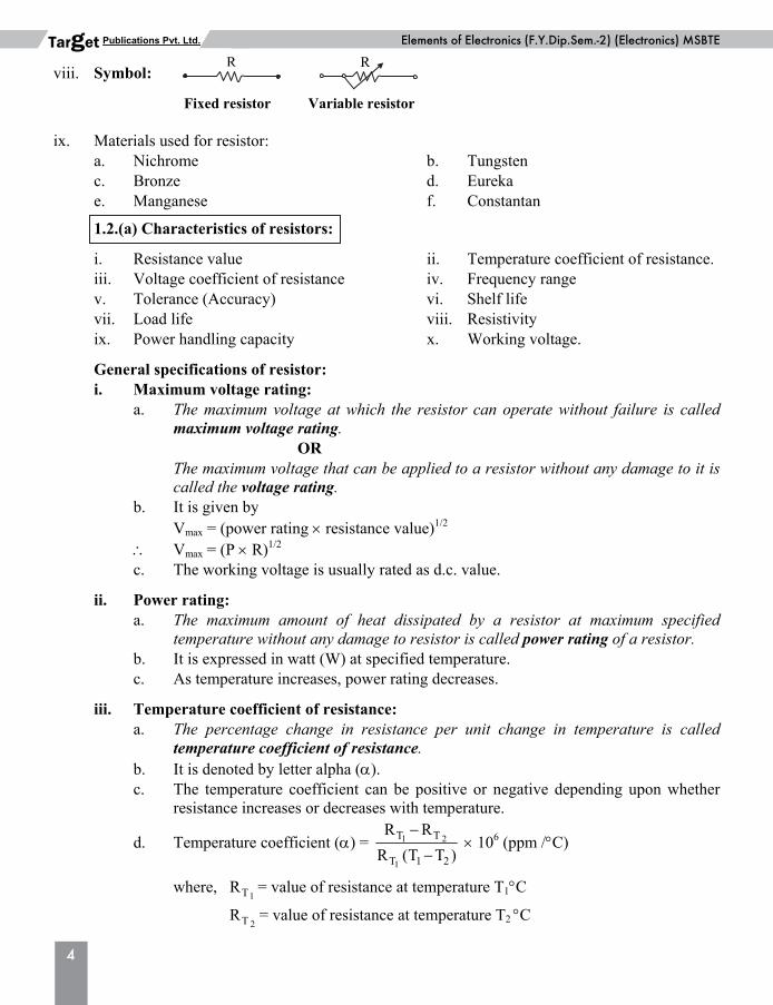
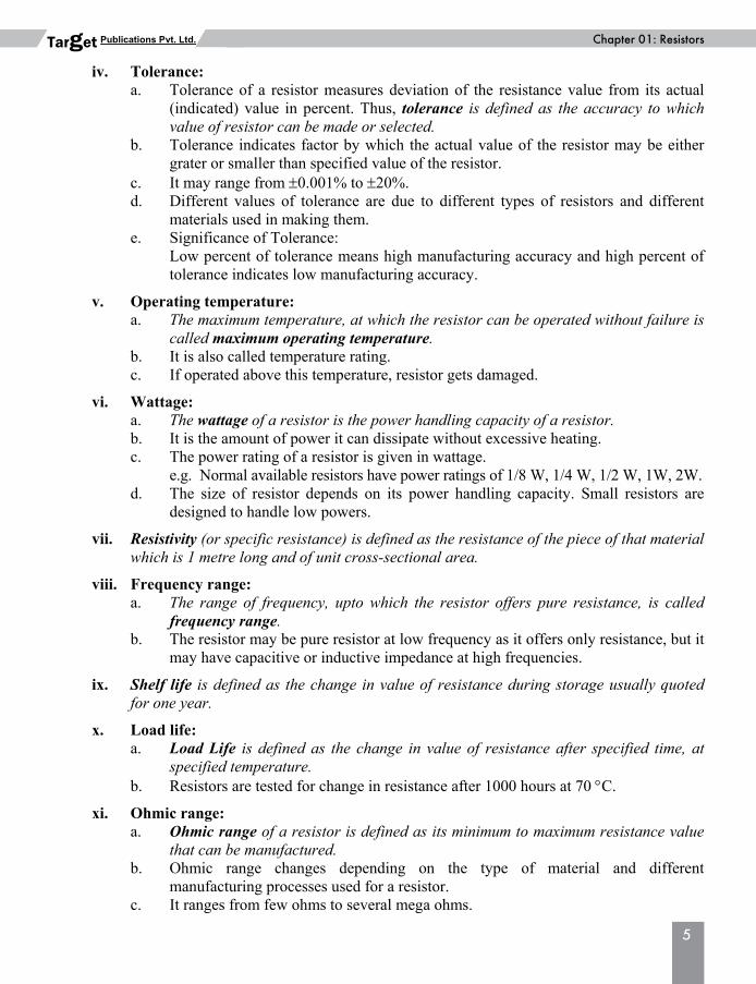
Elements of Electronics (F.Y.Dip.Sem.-2) (Electronics) MSBTEPublications Pvt. Ltd. Target viii. Symbol: ix. Materials used for resistor: a. Nichrome b. Tungsten c. Bronze d. Eureka e. Manganese f. Constantan 1.2.(a) Characteristics of resistors: i. Resistance value ii. Temperature coefficient of resistance. iii. Voltage coefficient of resistance iv. Frequency range v. Tolerance (Accuracy) vi. Shelf life vii. Load life viii. Resistivity ix. Power handling capacity x. Working voltage. General specifications of resistor: i. Maximum voltage rating: a. The maximum voltage at which the resistor can operate without failure is called
maximum voltage rating. OR The maximum voltage that can be applied to a resistor without any damage to it is
called the voltage rating. b. It is given by Vmax = (power rating resistance value)1/2 Vmax = (P R)1/2 c. The working voltage is usually rated as d.c. value. ii. Power rating: a. The maximum amount of heat dissipated by a resistor at maximum specified
temperature without any damage to resistor is called power rating of a resistor. b. It is expressed in watt (W) at specified temperature. c. As temperature increases, power rating decreases. iii. Temperature coefficient of resistance: a. The percentage change in resistance per unit change in temperature is called
temperature coefficient of resistance. b. It is denoted by letter alpha (). c. The temperature coefficient can be positive or negative depending upon whether
resistance increases or decreases with temperature.
d. Temperature coefficient () = 1 2
1
T T
T 1 2
R R
R (T T )
106 (ppm /C)
where, 1TR = value of resistance at temperature T1C
2TR = value of resistance at temperature T2 C
Fixed resistor
R R
Variable resistor
Basic Physics (F.Y.Dip.Sem.-1) MSBTEChapter 01: Resistors
5
Publications Pvt. Ltd. Target iv. Tolerance: a. Tolerance of a resistor measures deviation of the resistance value from its actual
(indicated) value in percent. Thus, tolerance is defined as the accuracy to which value of resistor can be made or selected.
b. Tolerance indicates factor by which the actual value of the resistor may be either grater or smaller than specified value of the resistor.
c. It may range from 0.001% to 20%. d. Different values of tolerance are due to different types of resistors and different
materials used in making them. e. Significance of Tolerance: Low percent of tolerance means high manufacturing accuracy and high percent of
tolerance indicates low manufacturing accuracy. v. Operating temperature: a. The maximum temperature, at which the resistor can be operated without failure is
called maximum operating temperature. b. It is also called temperature rating. c. If operated above this temperature, resistor gets damaged. vi. Wattage: a. The wattage of a resistor is the power handling capacity of a resistor. b. It is the amount of power it can dissipate without excessive heating. c. The power rating of a resistor is given in wattage. e.g. Normal available resistors have power ratings of 1/8 W, 1/4 W, 1/2 W, 1W, 2W. d. The size of resistor depends on its power handling capacity. Small resistors are
designed to handle low powers. vii. Resistivity (or specific resistance) is defined as the resistance of the piece of that material
which is 1 metre long and of unit cross-sectional area. viii. Frequency range: a. The range of frequency, upto which the resistor offers pure resistance, is called
frequency range. b. The resistor may be pure resistor at low frequency as it offers only resistance, but it
may have capacitive or inductive impedance at high frequencies. ix. Shelf life is defined as the change in value of resistance during storage usually quoted
for one year. x. Load life: a. Load Life is defined as the change in value of resistance after specified time, at
specified temperature. b. Resistors are tested for change in resistance after 1000 hours at 70 C. xi. Ohmic range: a. Ohmic range of a resistor is defined as its minimum to maximum resistance value
that can be manufactured. b. Ohmic range changes depending on the type of material and different
manufacturing processes used for a resistor. c. It ranges from few ohms to several mega ohms.
6
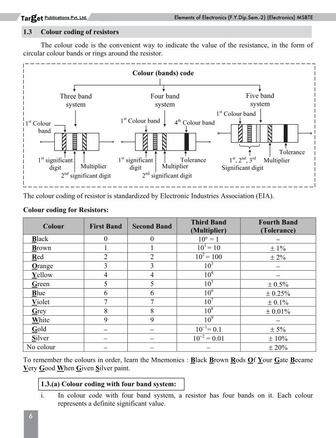
Elements of Electronics (F.Y.Dip.Sem.-2) (Electronics) MSBTEPublications Pvt. Ltd. Target 1.3 Colour coding of resistors The colour code is the convenient way to indicate the value of the resistance, in the form of circular colour bands or rings around the resistor. The colour coding of resistor is standardized by Electronic Industries Association (EIA). Colour coding for Resistors:
Colour First Band Second Band Third Band (Multiplier)
Fourth Band (Tolerance)
Black 0 0 10 = 1 Brown 1 1 101 = 10 1% Red 2 2 102 = 100 2% Orange 3 3 103 Yellow 4 4 104 Green 5 5 105 0.5% Blue 6 6 106 0.25% Violet 7 7 107 0.1% Grey 8 8 108 0.01% White 9 9 109 Gold 101= 0.1 5% Silver 102 = 0.01 10%
No colour 20% To remember the colours in order, learn the Mnemonics : Black Brown Rods Of Your Gate Became Very Good When Given Silver paint. 1.3.(a) Colour coding with four band system: i. In colour code with four band system, a resistor has four bands on it. Each colour
represents a definite significant value.
Colour (bands) code
Four bandsystem
Five band system
Three bandsystem
1st, 2nd, 3rd Significant digit
MultiplierTolerance
1st Colour band
1st significantdigit
2nd significant digit
Multiplier
1st Colour band
Tolerance
4th Colour band1st Colour band
1st significant digit
2nd significant digit
Multiplier
Basic Physics (F.Y.Dip.Sem.-1) MSBTEChapter 01: Resistors
7
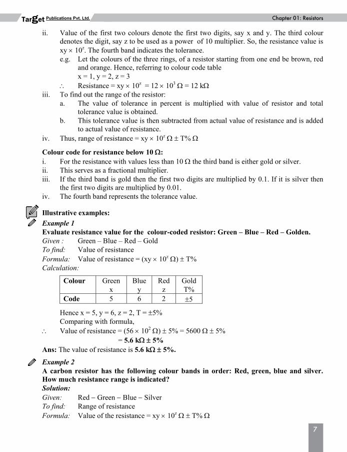
Publications Pvt. Ltd. Target ii. Value of the first two colours denote the first two digits, say x and y. The third colour
denotes the digit, say z to be used as a power of 10 multiplier. So, the resistance value is xy 10z. The fourth band indicates the tolerance.
e.g. Let the colours of the three rings, of a resistor starting from one end be brown, red and orange. Hence, referring to colour code table
x = 1, y = 2, z = 3 Resistance = xy 10z = 12 103 = 12 k iii. To find out the range of the resistor: a. The value of tolerance in percent is multiplied with value of resistor and total
tolerance value is obtained. b. This tolerance value is then subtracted from actual value of resistance and is added
to actual value of resistance. iv. Thus, range of resistance = xy 10z T% Colour code for resistance below 10 : i. For the resistance with values less than 10 the third band is either gold or silver. ii. This serves as a fractional multiplier. iii. If the third band is gold then the first two digits are multiplied by 0.1. If it is silver then
the first two digits are multiplied by 0.01. iv. The fourth band represents the tolerance value. Illustrative examples: Example 1 Evaluate resistance value for the colour-coded resistor: Green – Blue – Red – Golden. Given : Green – Blue – Red – Gold To find: Value of resistance Formula: Value of resistance = (xy 10z ) T% Calculation:
Colour
Green x
Blue y
Red z
Gold T%
Code 5 6 2 5 Hence x = 5, y = 6, z = 2, T = 5% Comparing with formula, Value of resistance = (56 102 ) 5% = 5600 5% = 5.6 k 5% Ans: The value of resistance is 5.6 k 5%. Example 2 A carbon resistor has the following colour bands in order: Red, green, blue and silver. How much resistance range is indicated? Solution: Given: Red Green Blue Silver To find: Range of resistance Formula: Value of the resistance = xy 10z T%
8
Elements of Electronics (F.Y.Dip.Sem.-2) (Electronics) MSBTEPublications Pvt. Ltd. Target Calculation:
Colour Red x
Green y
Blue z
Silver T%
Colour code 2 5 6 10 Here, x = 2, y = 5, z = 6, T = 10% Comparing with formula, Value of resistance = 25 106 10% To find out range,
10% of (25 106) = 25 106 10
100= 25 105 ,
the range of the resistance is (25 106 10%) = (25 106 25 105) i.e., between 22.5 106 and
27.5 106 . Ans: The range of the resistance is (25 106 25 105) or between 22.5 106 and
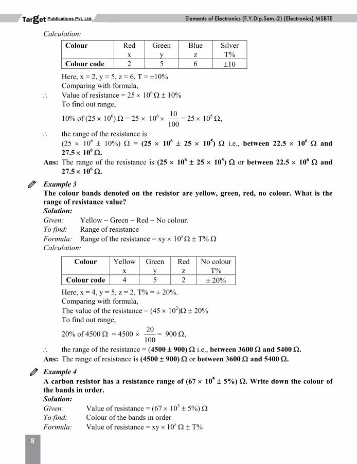
27.5 106 . Example 3 The colour bands denoted on the resistor are yellow, green, red, no colour. What is the
range of resistance value? Solution: Given: Yellow Green Red No colour. To find: Range of resistance Formula: Range of the resistance = xy 10z T% Calculation:
Colour Yellow x
Green y
Red z
No colour T%
Colour code 4 5 2 20% Here, x = 4, y = 5, z = 2, T% = ± 20%. Comparing with formula, The value of the resistance = (45 102) 20% To find out range,
20% of 4500 = 4500 20
100= 900 ,
the range of the resistance = (4500 900) i.e., between 3600 and 5400 . Ans: The range of resistance is (4500 900) or between 3600 and 5400 . Example 4 A carbon resistor has a resistance range of (67 105 5%) . Write down the colour of
the bands in order. Solution: Given: Value of resistance = (67 105 5%) To find: Colour of the bands in order Formula: Value of resistance = xy 10z T%
Basic Physics (F.Y.Dip.Sem.-1) MSBTEChapter 01: Resistors
9
Publications Pvt. Ltd. Target Calculation: Value of resistance = (67 105 5%) = 67 105 5% Comparing this with the formula, here x = 6, y = 7, z = 5, T = 5% Referring to colour code table, The first ring/colour for x = 6 is blue. The second ring/colour for y = 7 is violet, The third ring/colour for z = 5 is green. The fourth ring/colour for T = 5% is gold. Hence, colour bands on the given resistor are Blue Violet Green Gold Ans: The colour of the bands of the resistor in order are Blue – Violet – Green – Gold. Example 5 Using colour code, write the colour codes for the following resistors 4.7 Ω, ± 5%. Given: Value of resistance = (4.7 5%) To find: Colour of the bands in order Formula: Value of resistance = xy 10z T% Calculation: Value of resistance = (4.7 5%) = 47 101 5% Comparing this with the formula, here x = 4, y = 7, z = 1, T = 5% Referring to colour code table, The first ring/colour for x = 4 is Yellow. The second ring/colour for y = 7 is Violet. The third ring/colour for z = 1 is Gold. The fourth ring/colour for T = 5% is Gold. Hence, colour bands on the given resistor are Yellow Violet Gold Gold Ans: The colour of the bands of the resistor are Yellow Violet Gold Gold. 1.3.(b) Colour coding with three band system: For resistor with only three colour bands and no fourth tolerance band, its value is calculated as
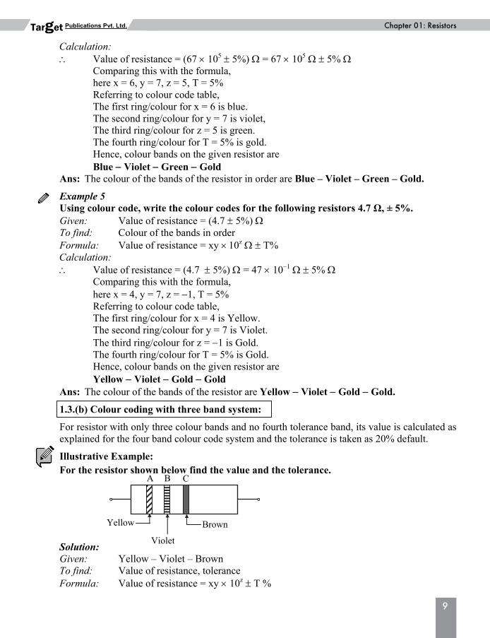
explained for the four band colour code system and the tolerance is taken as 20% default. Illustrative Example: For the resistor shown below find the value and the tolerance. Solution: Given: Yellow – Violet – Brown To find: Value of resistance, tolerance Formula: Value of resistance = xy 10z T %
Yellow Brown
Violet
A B C
10
Elements of Electronics (F.Y.Dip.Sem.-2) (Electronics) MSBTEPublications Pvt. Ltd. Target Calculation: The value of the given resistance is,
Colour Yellow x
Violet y
Brown z
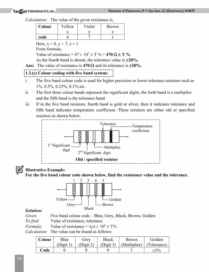
code 4 7 1 Here, x = 4, y = 7, z = 1 From formula, Value of resistance = 47 101 T % = 470 T % As the fourth band is absent, the tolerance value is 20%. Ans: The value of resistance is 470 and its tolerance is 20%. 1.3.(c) Colour coding with five band system: i. The five band colour code is used for higher precision or lower tolerance resistors such as
1%, 0.5%, 0.25%, 0.1% etc. ii. The first three colour bands represent the significant digits, the forth band is a multiplier
and the fifth band is the tolerance band. iii. If in the five band resistors, fourth band is gold or silver, then it indicates tolerance and
fifth band indicates temperature coefficient. These resistors are either old or specified resistors as shown below.
Illustrative Example: For the five band colour code shown below, find the resistance value and the tolerance. Solution: Given: Five band colour code – Blue, Grey, Black, Brown, Golden To find: Value of resistance, tolerance Formula: Value of resistance = xyz 10n T% Calculation: The value can be found as follows:
Colour Blue (Digit 1)
Grey (Digit 2)
Black (Digit 3)
Brown (Multiplier)
Golden (Tolerance)
Code 6 8 0 1 5%
YellowBrownGrey
1 2 3
Golden
Black
4 5
1st Significantdigit
Multiplier
Tolerance Temperature coefficient
2nd Significant digit
Old / specified resistor
Basic Physics (F.Y.Dip.Sem.-1) MSBTEChapter 01: Resistors
11
Publications Pvt. Ltd. Target Here, x = 6, y = 8, z = 0, n = 1, T = 5% From formula, The value resistance = 680 101 = 6.8 k and tolerance is 5% Ans: The value resistance is 6.8 k and tolerance is 5%.
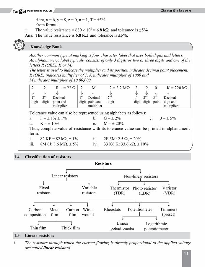
1.4 Classification of resistors 1.5 Linear resistors i. The resistors through which the current flowing is directly proportional to the applied voltage
are called linear resistors.
Linear resistors Non-linear resistors
Fixed resistors
Variableresistors
Thermistor(TDR)
Photo resistor (LDR)
Varistor(VDR)
Carbon composition
Metal film
Carbon film
Wire- wound
Trimmers (preset)
Potentiometer Rheostats
Linear potentiometer
Logarithmic potentiometer Thin film Thick film
Resistors
Another common type at marking is four character label that uses both digits and letters. An alphanumeric label typically consists of only 3 digits or two or three digits and one of the letters R (ORE), K or M. The letter is used to indicate the multiplier and its position indicates decimal point placement. R (ORE) indicates multiplier of 1, K indicates multiplier of 1000 and M indicates multiplier of 10,00,000 2 2 R = 22 1st 2nd Decimal digit digit point and multiplier
2 M 2 = 2.2 M 1st Decimal 2nd digit point and digit multiplier
2 2 0 K = 220 k 1st 2nd 3rd Decimal digit digit point digit and multiplier
Tolerance value can also be represented using alphabets as follows: a. F = 1% 1% b. G = 2% c. J = 5% d. K = 10% e. M = 20% Thus, complete value of resistance with its tolerance value can be printed in alphanumeric form. i. 82 KF = 82 k, 1% ii. 2E 5M: 2.5 , 20% iii. 8M 6J: 8.6 M, 5% iv. 33 K6 K: 33.6 k, 10%
Knowledge Bank
12
Elements of Electronics (F.Y.Dip.Sem.-2) (Electronics) MSBTEPublications Pvt. Ltd. Target ii. Resistance value of linear resistor does not change with the variations in applied voltage,
temperature and light intensity. iii. Linear resistors are of two types fixed resistors and variable resistors. 1.5.(a) Fixed linear resistors: The linear resistors whose resistance value does not change with the variation in applied
voltage, operating temperature and light intensity and also it has fixed value of resistance that cannot be varied manually are called fixed linear resistors.
Application of fixed linear resistors: i. Used to control the flow of current ii. Used in biasing of a device iii. Used in coupling networks iv. Used in feedback networks v. Used in amplifier circuits vi. Used in waveform generators vii. Used in oscillators viii. Used in radio and T.V. receivers Carbon film resistor, wire wound resistor, carbon composition resistor are some types of fixed
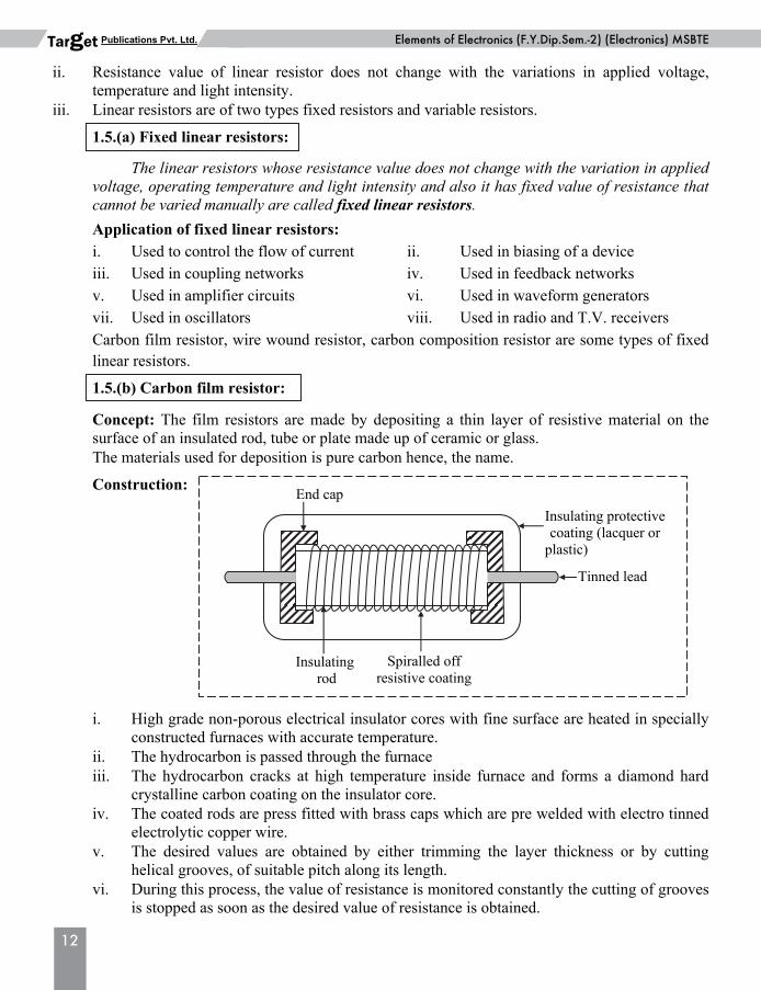
linear resistors. 1.5.(b) Carbon film resistor: Concept: The film resistors are made by depositing a thin layer of resistive material on the
surface of an insulated rod, tube or plate made up of ceramic or glass. The materials used for deposition is pure carbon hence, the name. Construction: i. High grade non-porous electrical insulator cores with fine surface are heated in specially
constructed furnaces with accurate temperature. ii. The hydrocarbon is passed through the furnace iii. The hydrocarbon cracks at high temperature inside furnace and forms a diamond hard
crystalline carbon coating on the insulator core. iv. The coated rods are press fitted with brass caps which are pre welded with electro tinned
electrolytic copper wire. v. The desired values are obtained by either trimming the layer thickness or by cutting
helical grooves, of suitable pitch along its length. vi. During this process, the value of resistance is monitored constantly the cutting of grooves
is stopped as soon as the desired value of resistance is obtained.
End cap
Insulating rod
Spiralled off resistive coating
Tinned lead
Insulating protectivecoating (lacquer or
plastic)
Basic Physics (F.Y.Dip.Sem.-1) MSBTEChapter 01: Resistors
13
Publications Pvt. Ltd. Target vii. The contact caps are fitted on both ends. The load wires made of tinned copper are then
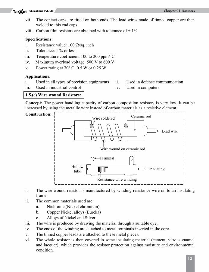
welded to this end caps. viii. Carbon film resistors are obtained with tolerance of 1% Specifications: i. Resistance value: 100 /sq. inch ii. Tolerance: 1 % or less iii. Temperature coefficient: 100 to 200 ppm/C iv. Maximum overload voltage: 500 V to 600 V v. Power rating at 70 C: 0.5 W or 0.25 W Applications: i. Used in all types of precision equipments ii. Used in defence communication iii. Used in industrial control iv. Used in computers. 1.5.(c) Wire wound Resistors: Concept: The power handling capacity of carbon composition resistors is very low. It can be
increased by using the metallic wire instead of carbon materials as a resistive element. Construction: i. The wire wound resistor is manufactured by winding resistance wire on to an insulating
frame. ii. The common materials used are a. Nichrome (Nickel chromium) b. Copper Nickel alloys (Eureka) c. Alloys of Nickel and Silver iii. The wire is produced by drawing the material through a suitable dye. iv. The ends of the winding are attached to metal terminals inserted in the core. v. The tinned copper leads are attached to these metal pieces. vi. The whole resistor is then covered in some insulating material (cement, vitrous enamel
and lacquer), which provides the resistor protection against moisture and environmental condition.
Wire soldered
Wire wound on ceramic rod
Lead wire
Ceramic rod
Terminal
Hollowtube
outer coating
Resistance wire winding
14
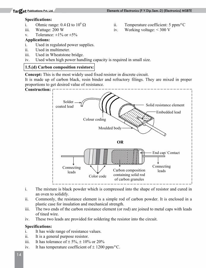
Elements of Electronics (F.Y.Dip.Sem.-2) (Electronics) MSBTEPublications Pvt. Ltd. Target Specifications: i. Ohmic range: 0.4 to 106 ii. Temperature coefficient: 5 ppm/C iii. Wattage: 200 W iv. Working voltage: < 300 V v. Tolerance: ±1% or ±5% Applications: i. Used in regulated power supplies. ii. Used in multimeter. iii. Used in Wheatstone bridge. iv. Used when high power handling capacity is required in small size. 1.5.(d) Carbon composition resistors: Concept: This is the most widely used fixed resistor in discrete circuit. It is made up of carbon black, resin binder and refractory filings. They are mixed in proper
proportions to get desired value of resistance. Construction: i. The mixture is black powder which is compressed into the shape of resistor and cured in
an oven to solidify. ii. Commonly, the resistance element is a simple rod of carbon powder. It is enclosed in a
plastic case for insulation and mechanical strength. iii. The two ends of the carbon resistance element (or rod) are joined to metal caps with leads
of tined wire. iv. These two leads are provided for soldering the resistor into the circuit. Specifications: i. It has wide range of resistance values. ii. It is a general purpose resistor. iii. It has tolerance of 5%, 10% or 20% iv. It has temperature coefficient of 1200 ppm/C.
OR
Moulded body
Embedded lead
Soldercoated lead
Colour coding
Solid resistance element
Connectingleads
End cap/ Contact
Carbon compositioncontaining solid rod of carbon granules
Connecting leads
Color code
Basic Physics (F.Y.Dip.Sem.-1) MSBTEChapter 01: Resistors
15
Publications Pvt. Ltd. Target v. It has wide temperature range, typically 55 C to + 150 C. vi. It is capable of operating safely upto about 800 V. vii. It has voltage coefficient of 0.5 V d.c. viii. It is available in the power ratings of 1/8 W, 1/4 W, 1/2 W, 1 W and 2 W. ix. It has frequency range upto 20 kHz. x. The thermal noise and current noise are present. Applications: i. Used in high frequency low power applications. ii. Used in the power control circuits. iii. Used in general purpose electronic equipments such as potential divider, amplifiers,
zener voltage regulator. iv. Used in d.c. power supplies. v. Used in radio and T.V. receivers (low wattage blocks). 1.6 Variable linear resistors i. The linear resistor, whose resistance value does not change with the variation in applied
voltage, operating temperature and light intensity but its resistance value can be varied manually to its maximum specified limit, is called variable linear resistor.
ii. Trimmers, rheostat, potentiometers are some types of variable linear resistors. 1.6.(a) Potentiometers: Concept: The potentiometers are variable linear resistors that deliver an output voltage
representing some function of an applied voltage and shaft position. It is small in size and is usually referred as “pot”.
Applications of potentiometers: i. Used as a voltage divider in the electronic circuits. ii. Used as a volume control, tone control or brightness controls in radio and T.V. receivers. Types: Depending upon the type of resistance element, the potentiometers come in many types such as
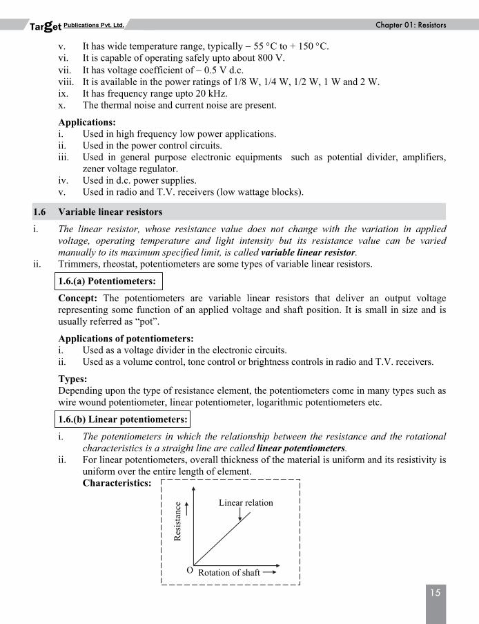
wire wound potentiometer, linear potentiometer, logarithmic potentiometers etc. 1.6.(b) Linear potentiometers: i. The potentiometers in which the relationship between the resistance and the rotational
characteristics is a straight line are called linear potentiometers. ii. For linear potentiometers, overall thickness of the material is uniform and its resistivity is
uniform over the entire length of element. Characteristics:
Linear relation
Rotation of shaft
Res
ista
nce
O
16
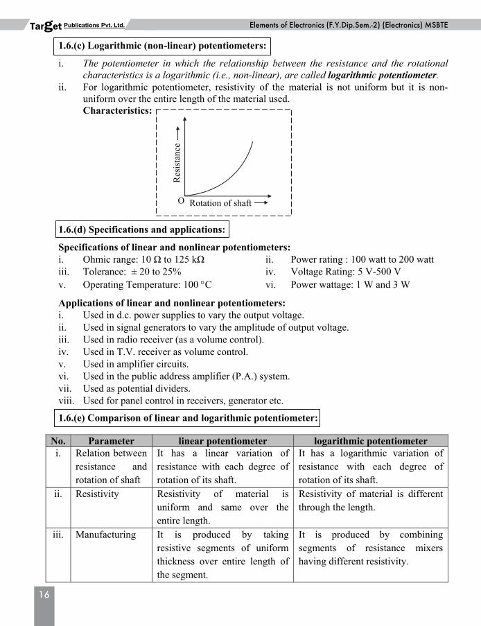
Elements of Electronics (F.Y.Dip.Sem.-2) (Electronics) MSBTEPublications Pvt. Ltd. Target 1.6.(c) Logarithmic (non-linear) potentiometers: i. The potentiometer in which the relationship between the resistance and the rotational
characteristics is a logarithmic (i.e., non-linear), are called logarithmic potentiometer. ii. For logarithmic potentiometer, resistivity of the material is not uniform but it is non-
uniform over the entire length of the material used. Characteristics: 1.6.(d) Specifications and applications: Specifications of linear and nonlinear potentiometers: i. Ohmic range: 10 Ω to 125 kΩ ii. Power rating : 100 watt to 200 watt iii. Tolerance: ± 20 to 25% iv. Voltage Rating: 5 V-500 V v. Operating Temperature: 100 C vi. Power wattage: 1 W and 3 W Applications of linear and nonlinear potentiometers: i. Used in d.c. power supplies to vary the output voltage. ii. Used in signal generators to vary the amplitude of output voltage. iii. Used in radio receiver (as a volume control). iv. Used in T.V. receiver as volume control. v. Used in amplifier circuits. vi. Used in the public address amplifier (P.A.) system. vii. Used as potential dividers. viii. Used for panel control in receivers, generator etc. 1.6.(e) Comparison of linear and logarithmic potentiometer:
No. Parameter linear potentiometer logarithmic potentiometer i. Relation between
resistance and rotation of shaft
It has a linear variation of resistance with each degree of rotation of its shaft.
It has a logarithmic variation of resistance with each degree of rotation of its shaft.
ii. Resistivity Resistivity of material is uniform and same over the entire length.
Resistivity of material is different through the length.
iii. Manufacturing It is produced by taking resistive segments of uniform thickness over entire length of the segment.
It is produced by combining segments of resistance mixers having different resistivity.
Rotation of shaft
Res
ista
nce
O
Basic Physics (F.Y.Dip.Sem.-1) MSBTEChapter 01: Resistors
17
Publications Pvt. Ltd. Target iv. Characteristic
curve
v. Costing Linear potentiometers are less expensive as compared to logarithmic potentiometers.
Logarithmic potentiometers are more expensive as compared to linear potentiometers.
vi. Application In consumer electronics, user control uses linear potentiometers.
Logarithmic potentiometers are often used in connection with audio amplifiers.
1.7 Non-linear resistors i. The resistor, through which the flow of current is not directly proportional to the applied
voltage is called non-linear resistor. ii. These resistors are made from semiconducting materials. iii. The value of non-linear resistor depends on applied voltage, temperature and light intensity. Types of non-linear resistors: i. Thermistor i.e., temperature dependent resistor (TDR). This includes NTC thermistor and PTC
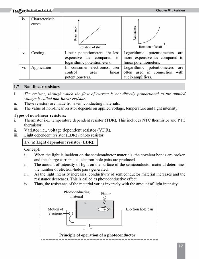
thermistor. ii. Varistor i.e., voltage dependent resistor (VDR). iii. Light dependent resistor (LDR) / photo resistor. 1.7.(a) Light dependent resistor (LDR): Concept: i. When the light is incident on the semiconductor materials, the covalent bonds are broken
and the charge carriers i.e., electron-hole pairs are produced. ii. The amount of intensity of light on the surface of the semiconductor material determines
the number of electron-hole pairs generated. iii. As the light intensity increases, conductivity of semiconductor material increases and the
resistance decreases. This is called as photoconductive effect. iv. Thus, the resistance of the material varies inversely with the amount of light intensity.
Rotation of shaft
Res
ista
nce
Rotation of shaft
Res
ista
nce
+
Photon
Electron hole pair
Photoconductingmaterial
Motion of electrons
+
Principle of operation of a photoconductor
18
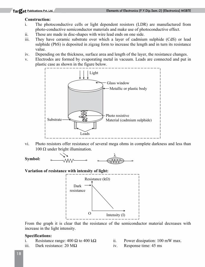
Elements of Electronics (F.Y.Dip.Sem.-2) (Electronics) MSBTEPublications Pvt. Ltd. Target Construction: i. The photoconductive cells or light dependent resistors (LDR) are manufactured from
photo-conductive semiconductor materials and make use of photoconductive effect. ii. These are made in disc-shapes with wire lead ends on one side. iii. They have ceramic substrate over which a layer of cadmium sulphide (CdS) or lead
sulphide (PbS) is deposited in zigzag form to increase the length and in turn its resistance value.
iv. Depending on the thickness, surface area and length of the layer, the resistance changes. v. Electrodes are formed by evaporating metal in vacuum. Leads are connected and put in
plastic case as shown in the figure below. vi. Photo resistors offer resistance of several mega ohms in complete darkness and less than
100 under bright illumination. Symbol: Variation of resistance with intensity of light: From the graph it is clear that the resistance of the semiconductor material decreases with
increase in the light intensity. Specifications: i. Resistance range: 400 Ω to 400 kΩ ii. Power dissipation: 100 mW max. iii. Dark resistance: 20 MΩ iv. Response time: 45 ms
Intensity (I)
Resistance (k)
O
Dark resistance
Glass window
Metallic or plastic body
Photo resistive Material (cadmium sulphide)
Leads
Substrate
Light
Basic Physics (F.Y.Dip.Sem.-1) MSBTEChapter 01: Resistors
19
Publications Pvt. Ltd. Target Applications: i. Used for automatic contrast and brightness control in T.V. receivers. ii. Used in street light control circuits. iii. Used in security alarms. iv. Used in smoke detectors. v. Used in photosensitive relay. vi. Used as a proximity switch. vii. Used in optical coding. viii. Used in light (flux) meter. ix. Used in camera light meters. x. Used in the infrared astronomy. 1.7.(b) Thermistors (TDR): Concept: i. It is a temperature sensitive resistor or temperature dependent resistor (TDR). ii. It is a nonlinear resistor for which the variation in temperature is reflected through an
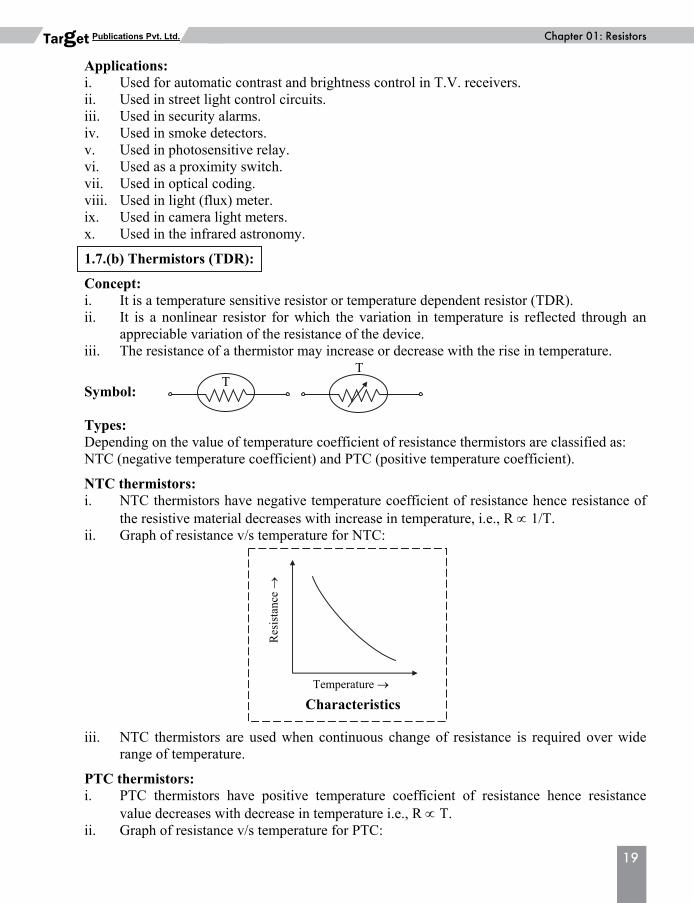
appreciable variation of the resistance of the device. iii. The resistance of a thermistor may increase or decrease with the rise in temperature. Symbol: Types: Depending on the value of temperature coefficient of resistance thermistors are classified as: NTC (negative temperature coefficient) and PTC (positive temperature coefficient). NTC thermistors: i. NTC thermistors have negative temperature coefficient of resistance hence resistance of
the resistive material decreases with increase in temperature, i.e., R 1/T. ii. Graph of resistance v/s temperature for NTC: iii. NTC thermistors are used when continuous change of resistance is required over wide
range of temperature. PTC thermistors: i. PTC thermistors have positive temperature coefficient of resistance hence resistance
value decreases with decrease in temperature i.e., R T. ii. Graph of resistance v/s temperature for PTC:
TT
Temperature
Res
ista
nce
Characteristics
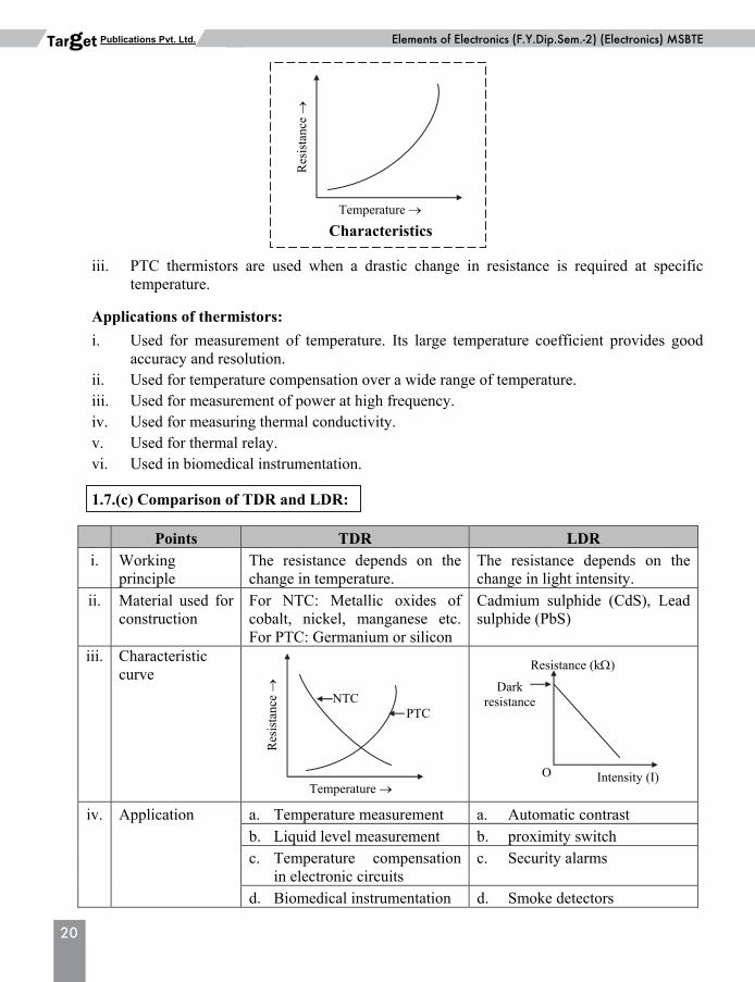
20
Elements of Electronics (F.Y.Dip.Sem.-2) (Electronics) MSBTEPublications Pvt. Ltd. Target iii. PTC thermistors are used when a drastic change in resistance is required at specific
temperature. Applications of thermistors:
i. Used for measurement of temperature. Its large temperature coefficient provides good accuracy and resolution.
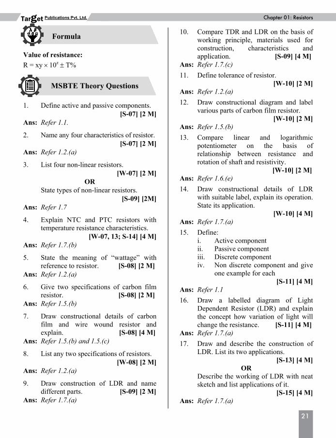
ii. Used for temperature compensation over a wide range of temperature. iii. Used for measurement of power at high frequency. iv. Used for measuring thermal conductivity. v. Used for thermal relay. vi. Used in biomedical instrumentation. 1.7.(c) Comparison of TDR and LDR:
Points TDR LDR i. Working
principle The resistance depends on the change in temperature.
The resistance depends on the change in light intensity.
ii. Material used for construction
For NTC: Metallic oxides of cobalt, nickel, manganese etc. For PTC: Germanium or silicon
Cadmium sulphide (CdS), Lead sulphide (PbS)
iii. Characteristic curve
iv. Application a. Temperature measurement a. Automatic contrast b. Liquid level measurement b. proximity switch c. Temperature compensation
in electronic circuits c. Security alarms
d. Biomedical instrumentation d. Smoke detectors
Temperature
Res
ista
nce
NTCPTC
Intensity (I)
Resistance (k)
O
Dark resistance
Characteristics
Temperature
Res
ista
nce
Basic Physics (F.Y.Dip.Sem.-1) MSBTEChapter 01: Resistors
21
Publications Pvt. Ltd. Target
MSBTE Theory Questions
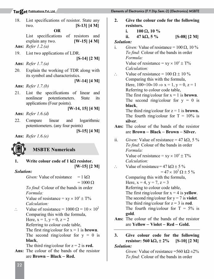
Formula Value of resistance:
R = xy 10z T% 1. Define active and passive components.
[S-07] [2 M] Ans: Refer 1.1. 2. Name any four characteristics of resistor.
[S-07] [2 M] Ans: Refer 1.2.(a) 3. List four non-linear resistors.
[W-07] [2 M] OR
State types of non-linear resistors. [S-09] [2M]
Ans: Refer 1.7 4. Explain NTC and PTC resistors with
temperature resistance characteristics. [W-07, 13; S-14] [4 M]
Ans: Refer 1.7.(b) 5. State the meaning of “wattage” with
reference to resistor. [S-08] [2 M] Ans: Refer 1.2.(a) 6. Give two specifications of carbon film
resistor. [S-08] [2 M] Ans: Refer 1.5.(b) 7. Draw constructional details of carbon
film and wire wound resistor and explain. [S-08] [4 M]
Ans: Refer 1.5.(b) and 1.5.(c) 8. List any two specifications of resistors.
[W-08] [2 M] Ans: Refer 1.2.(a) 9. Draw construction of LDR and name
different parts. [S-09] [2 M] Ans: Refer 1.7.(a)
10. Compare TDR and LDR on the basis of working principle, materials used for construction, characteristics and application. [S-09] [4 M]
Ans: Refer 1.7.(c) 11. Define tolerance of resistor.
[W-10] [2 M] Ans: Refer 1.2.(a) 12. Draw constructional diagram and label
various parts of carbon film resistor. [W-10] [2 M]
Ans: Refer 1.5.(b) 13. Compare linear and logarithmic
potentiometer on the basis of relationship between resistance and rotation of shaft and resistivity.
[W-10] [2 M] Ans: Refer 1.6.(e) 14. Draw constructional details of LDR
with suitable label, explain its operation. State its application.
[W-10] [4 M] Ans: Refer 1.7.(a) 15. Define: i. Active component ii. Passive component iii. Discrete component iv. Non discrete component and give
one example for each [S-11] [4 M]
Ans: Refer 1.1 16. Draw a labelled diagram of Light
Dependent Resistor (LDR) and explain the concept how variation of light will change the resistance. [S-11] [4 M]
Ans: Refer 1.7.(a) 17. Draw and describe the construction of
LDR. List its two applications. [S-13] [4 M]
OR Describe the working of LDR with neat
sketch and list applications of it. [S-15] [4 M]
Ans: Refer 1.7.(a)
22
Elements of Electronics (F.Y.Dip.Sem.-2) (Electronics) MSBTEPublications Pvt. Ltd. Target
MSBTE Numericals
18. List specifications of resistor. State any two. [S-13] [4 M]
OR List specifications of resistors and
explain any two. [W-15] [4 M] Ans: Refer 1.2.(a) 19. List two applications of LDR.
[S-14] [2 M] Ans: Refer 1.7.(a) 20. Explain the working of TDR along with
its symbol and characteristics. [W-14] [4 M]
Ans: Refer 1.7.(b) 21. List the specifications of linear and
nonlinear potentiometers. State its applications (Four points).
[W-14, 15] [4 M] Ans: Refer 1.6.(d) 22. Compare linear and logarithmic
potentiometers. (any four points) [S-15] [4 M]
Ans: Refer 1.6.(e) 1. Write colour code of 1 k resistor.
[W-15] [2 M] Solution: Given: Value of resistance = 1 k = 1000 To find: Colour of the bands in order Formula: Value of resistance = xy 10z T% Calculation: Value of resistance = 1000 = 10 102 Comparing this with the formula, Here, x = 1, y = 0, z = 2 Referring to colour code table, The first ring/colour for x = 1 is brown. The second ring/colour for y = 0 is
black, The third ring/colour for z = 2 is red. Ans: The colour of the bands of the resistor
are Brown Black Red.
2. Give the colour code for the following resistors.
i. 100 , 10 % ii. 47 k, 5 % [S-08] [2 M] Solution: i. Given: Value of resistance = 100 , 10 % To find: Colour of the bands in order Formula: Value of resistance = xy 10z T% Calculation: Value of resistance = 100 10 % Comparing this with the formula, Here, 100=1010 x = 1, y = 0, z = 1 Referring to colour code table, The first ring/colour for x = 1 is brown. The second ring/colour for y = 0 is
black, The third ring/colour for z = 1 is brown. The fourth ring/colour for T = 10% is
silver. Ans: The colour of the bands of the resistor
are Brown Black Brown Silver. ii. Given: Value of resistance = 47 k, 5 % To find: Colour of the bands in order Formula: Value of resistance = xy 10z T% Calculation: Value of resistance = 47 k 5 % = 47 103 5 % Comparing this with the formula, Here, x = 4, y = 7, z = 3 Referring to colour code table, The first ring/colour for x = 4 is yellow. The second ring/colour for y = 7 is violet. The third ring/colour for z = 3 is red. The fourth ring/colour for T = 5% is
gold. Ans: The colour of the bands of the resistor
are Yellow Violet Red Gold. 3. Give colour code for the following
resistor: 560 k, 2% [S-10] [2 M] Solution: Given: Value of resistance =560 kΩ ±2% To find: Colour of the bands in order
Basic Physics (F.Y.Dip.Sem.-1) MSBTEChapter 01: Resistors
23
Publications Pvt. Ltd. Target Formula: Value of resistance = xy 10z T% Calculation: Value of resistance = 560 kΩ 2 % = 56 104 2 % Comparing this with the formula, Here, x = 5, y = 6, z = 4 Referring to colour code table, The first ring/colour for x = 5 is green. The second ring/colour for y = 6 is blue. The third ring/colour for z = 4 is yellow. The fourth ring/colour for T = 2% is
red. Ans: Colour code for 560 k 2 % is Green-
Blue-Yellow-Red. 4. Write colour codes for following
resistors. i. 470 k ± 5% ii. 1.2 M ± 10%. [S-14] [4 M] Solution: i. Given: Value of resistance = 470 kΩ ±5% To find: Colour of the bands in order Formula: Value of resistance = xy 10z T% Calculation: Value of resistance = 470 kΩ 5 % = 47 104 5 % Comparing this with the formula, Here, x = 4, y = 7, z = 4 Referring to colour code table, The first ring/colour for x = 4 is yellow. The second ring/colour for y = 7 is
violet. The third ring/colour for z = 4 is yellow. The fourth ring/colour for T = 5% is
gold. Ans: Colour bands on the given resistor are Yellow Violet Yellow Gold. ii. Given: Value of resistance = (1.2 M ± 10%) To find: Colour of the bands in order Formula: Value of resistance = xy 10z T%
Calculation: Value of resistance = (1.2 M ± 10%) = 1.2 106 10 %
= 12 105 10% Comparing this with the formula, here x = 1, y = 2, z = 5, T = 10% Referring to colour code table, The first ring/colour for x = 1 is brown. The second ring/colour for y = 2 is red. The third ring/colour for z = 5 is green. The fourth ring/colour for T = 10% is
silver. Ans: Colour bands on the given resistor are Brown Red Green Silver. 5. Using colour code, write the colour
codes for the following resistors – i. 680 kΩ, ± 5% ii. 3.3 Ω, ± 10%
[W-14, 15] [4 M] Solution: i. Given: Value of resistance = 680 kΩ, ± 5% To find: Colour of the bands in order Formula: Value of resistance = xy 10z T% Calculation: Value of resistance = 680 kΩ 5 % = 68 104 5 % Comparing this with the formula, Here, x = 6, y = 8, z = 4 Referring to colour code table, The first ring/colour for x = 6 is blue. The second ring/colour for y = 8 is grey. The third ring/colour for z = 4 is yellow. The fourth ring/colour for T = 5% is
gold. Ans: Colour bands on the given resistor are Blue Grey Yellow Gold ii. Given: Value of resistance =(3.3 10%) To find: Colour of the bands in order Formula: Value of resistance = xy 10z T%
24
Elements of Electronics (F.Y.Dip.Sem.-2) (Electronics) MSBTEPublications Pvt. Ltd. Target Calculation: Value of resistance = (3.3 10%) = 33 101 10% Comparing this with the formula, here x = 3, y = 3, z = 1, T = 10% Referring to colour code table, The first ring/colour for x = 3 is orange. The second ring/colour for y = 3 is
orange. The third ring/colour for z = 1 is gold. The fourth ring/colour for T = 10% is
silver. Ans: Colour bands on the given resistor are Orange Orange Gold Silver. 6. Using colour code, write colour code
for following resistor: i. 100 Ω + 5% ii. 4K7 + 10%
[S-13] [4 M] Solution: i. Given: Value of resistance = 100 + 5% To find: Colour of the bands in order Formula: Value of resistance = xy 10z T% Calculation: Value of resistance = 100 5% Comparing this with formula, Here100=1010x=1, y=0, z=1,T= 5% Referring to colour code table, The first ring/ colour for x = brown The second ring/colour for y = black The third ring/colour for z = brown The fourth ring/colour for T = gold Ans: Colour bands on the given resistor are
Brown – Black – Brown – Gold. ii. Given: Value of resistance = 4K7+10% = 4.7 103 10% = 47 102 10% To find: Colour of the bands in order Formula: Value of resistance = xy 10z T%
Calculation: Value of resistance = 47 102 10% Comparing this with formula, Here x = 4, y = 7, z = 2, T = 10% Referring to colour code table, The first ring/ colour for x = yellow The second ring/colour for y = violet The third ring/colour for z = red The fourth ring/colour for T = silver Ans: Colour bands on the given resistor are
Yellow – Violet – Red – Silver. 7. Calculate the value of following
resistors using colour code. i. Orange, blue, red, golden ii. Yellow, violet, orange iii. Brown, black, black, red iv. Brown, Black, Black Brown,
Brown. [W-13] [4 M] Solution: i. Given : Orange, blue, red, golden To find: value of resistance Formula: Value of resistance = (xy 10z ) T% Calculation:
Colour
Orange x
Blue y
Red z
Gold T%
Code 3 6 2 5 Hence x = 3, y = 6, z = 2, T = 5% Value of resistance = 36 102 5 % = 3600 5 % = 3.6 k 5 % Ans: Value of resistance is 3.6 k 5%. ii. Given : Yellow, violet, orange and
no colour for fourth band. To find: value of resistance Formula: Value of resistance = (xy 10z ) T% Calculation:
Colour
Yellowx
Violet y
Orange z
No colour
T% Code 4 7 3 20
Basic Physics (F.Y.Dip.Sem.-1) MSBTEChapter 01: Resistors
25
Publications Pvt. Ltd. Target Hence x = 4, y = 7, z = 3, T = 20% From formula, Value of resistance = 47 103 20% = 47000 20 % = 47 k 20 % Ans: Value of resistance is 47 k 20%. iii. Given : Brown, black, black, red To find: value of resistance Formula: Value of resistance = (xy 10z ) T% Calculation:
Colour
Brown x
Black y
Black z
Red T%
Code 1 0 0 2 Hence x = 1, y = 0, z = 0, T = 2% Value of resistance = 10 100 2 % = 10 2 % Ans: Value of resistance is 10 2%. iv. Given : Brown, Black, Black
Brown, Brown To find: value of resistance Formula: Value of resistance = (xyz 10n) T% Calculation: Colour
Brown x
Black y
Black z
Brownn
Brown T%
Code 1 0 0 1 1 Here, x = 1, y = 0, z = 0, n = 1, T = 1% Value of resistance = 100 101 1% = 1000 1 % = 1.0 k 1 % Ans: Value of resistance is 1 k 1%. 1. Classify Resistors. Ans: Refer 1.4 2. State applications of carbon film resistor
and wire wound resistor. Ans: Refer 1.5.(b) and 1.5.(c)
3. Explain construction of carbon composition resistor.
Ans: Refer 1.5.(d) 4. Give specification and applications of
carbon composition resistor. Ans: Refer 1.5.(d) 5. Draw the characteristics of linear and
logarithmic potentiometers. Ans: Refer 1.6.(b) and 1.6.(c) 6. Draw symbol of LDR. Ans: Refer 1.7.(a) 7. State types of TDR. Ans: Refer 1.7.(b) 1. Find colour code of following resistor i. 370 10% ii. 1.6 k, 5% iii. 560 k 5% iv. 23.4k 10% 2. Evaluate resistance range for the
following colour-coded resistor: i. Yellow – Violet –Black – Silver. ii. Brown – Black – Orange – Golden. iii. Grey Red Orange Gold. iv. Green Blue Yellow No colour
Answers to Practice Problems 1. i. Orange Violet Brown Silver ii. Brown Blue Red Gold iii. Green Blue Black Orange
Silver iv. Red Orange Yellow Red
Silver 2. The range of the given resistance is i. 47 4.7 or between 42.3
and 51.7 ii. 10 k 0.5 k or between
9.5 k and 10.5 k iii. 82 k 4.10 k or between 77.9 k and 86.1 k iv. 560 k 112 k or between
448 k and 672 k
Additional Theory Questions
Problems for Practice