Embed Size (px)
Citation preview

BEST MANAGEMENT PRACTICES MANUAL
FOR
CONSTRUCTION SITES IN HONOLULU
Prepared by the
Department of Environmental ServicesCity and County of Honolulu
in cooperation with
The General Contractors Association of Hawaii
May 1999
Help protect our waters ... for life!
OFFICE OF THE MAYORCITY AND COUNTY OF HONOLULU
MAYOR’S MESSAGE
The construction industry contributes greatly to our economy, growth and quality of life. It also has the potential to significantly impact our environment. Using best management practices(BMPs) at construction sites is the most effective way to prevent pollution and protect ourenvironment.
Engineers, contractors and inspectors, who support this idea have all expressed the need forguidance in the planning, building and maintenance of effective pollution control measures. ThisBest Management Practices Manual for Construction Sites in Honolulu, prepared in cooperationwith the General Contractors Association of Hawaii, provides a broad range of measures tocontrol erosion and the discharge of sediment and other pollutants into our environment.
Each BMP fact sheet in the manual clearly defines objectives, identifies pollutants andlists implementation requirements. The fact sheets present the principles behind each measure,such as containment, filtration, or simply the need for good housekeeping practices, and giveguidance for their effective application.
Please use the best management practices in this manual to keep pollutants out of our waterways. Together, with your kokua, we can meet our responsibilities as stewards entrusted to protectOahu’s streams and coastal waters.
JEREMY HARRIS, Mayor City and County of Honolulu
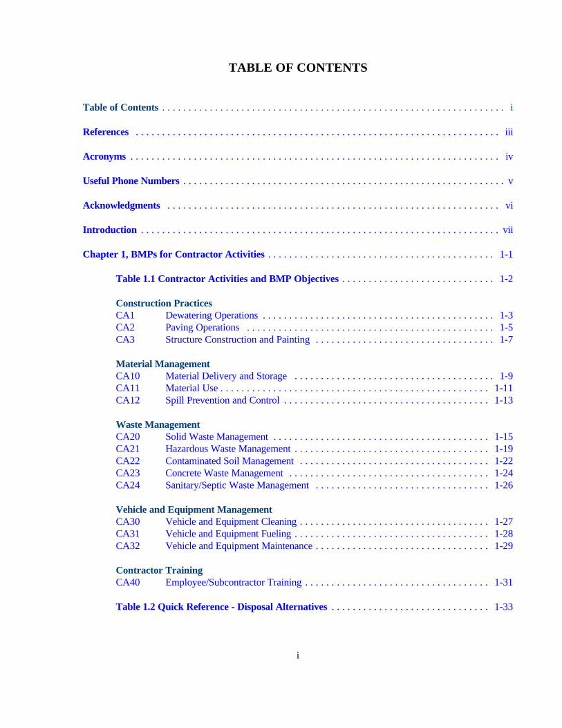
TABLE OF CONTENTS
Table of Contents . . . . . . . . . . . . . . . . . . . . . . . . . . . . . . . . . . . . . . . . . . . . . . . . . . . . . . . . . . . . . . . . . i
References . . . . . . . . . . . . . . . . . . . . . . . . . . . . . . . . . . . . . . . . . . . . . . . . . . . . . . . . . . . . . . . . . . . . . iii
Acronyms . . . . . . . . . . . . . . . . . . . . . . . . . . . . . . . . . . . . . . . . . . . . . . . . . . . . . . . . . . . . . . . . . . . . . . iv
Useful Phone Numbers . . . . . . . . . . . . . . . . . . . . . . . . . . . . . . . . . . . . . . . . . . . . . . . . . . . . . . . . . . . . . v
Acknowledgments . . . . . . . . . . . . . . . . . . . . . . . . . . . . . . . . . . . . . . . . . . . . . . . . . . . . . . . . . . . . . . . vi
Introduction . . . . . . . . . . . . . . . . . . . . . . . . . . . . . . . . . . . . . . . . . . . . . . . . . . . . . . . . . . . . . . . . . . . . vii
Chapter 1, BMPs for Contractor Activities . . . . . . . . . . . . . . . . . . . . . . . . . . . . . . . . . . . . . . . . . . . 1-1
Table 1.1 Contractor Activities and BMP Objectives . . . . . . . . . . . . . . . . . . . . . . . . . . . . . 1-2
Construction PracticesCA1 Dewatering Operations . . . . . . . . . . . . . . . . . . . . . . . . . . . . . . . . . . . . . . . . . . . . 1-3CA2 Paving Operations . . . . . . . . . . . . . . . . . . . . . . . . . . . . . . . . . . . . . . . . . . . . . . . 1-5CA3 Structure Construction and Painting . . . . . . . . . . . . . . . . . . . . . . . . . . . . . . . . . . 1-7
Material ManagementCA10 Material Delivery and Storage . . . . . . . . . . . . . . . . . . . . . . . . . . . . . . . . . . . . . . 1-9CA11 Material Use . . . . . . . . . . . . . . . . . . . . . . . . . . . . . . . . . . . . . . . . . . . . . . . . . . . 1-11CA12 Spill Prevention and Control . . . . . . . . . . . . . . . . . . . . . . . . . . . . . . . . . . . . . . . 1-13
Waste ManagementCA20 Solid Waste Management . . . . . . . . . . . . . . . . . . . . . . . . . . . . . . . . . . . . . . . . . 1-15CA21 Hazardous Waste Management . . . . . . . . . . . . . . . . . . . . . . . . . . . . . . . . . . . . . 1-19CA22 Contaminated Soil Management . . . . . . . . . . . . . . . . . . . . . . . . . . . . . . . . . . . . 1-22CA23 Concrete Waste Management . . . . . . . . . . . . . . . . . . . . . . . . . . . . . . . . . . . . . . 1-24CA24 Sanitary/Septic Waste Management . . . . . . . . . . . . . . . . . . . . . . . . . . . . . . . . . 1-26
Vehicle and Equipment ManagementCA30 Vehicle and Equipment Cleaning . . . . . . . . . . . . . . . . . . . . . . . . . . . . . . . . . . . . 1-27CA31 Vehicle and Equipment Fueling . . . . . . . . . . . . . . . . . . . . . . . . . . . . . . . . . . . . . 1-28CA32 Vehicle and Equipment Maintenance . . . . . . . . . . . . . . . . . . . . . . . . . . . . . . . . . 1-29
Contractor TrainingCA40 Employee/Subcontractor Training . . . . . . . . . . . . . . . . . . . . . . . . . . . . . . . . . . . 1-31
Table 1.2 Quick Reference - Disposal Alternatives . . . . . . . . . . . . . . . . . . . . . . . . . . . . . . 1-33
i

TABLE OF CONTENTS (continued)
Chapter 2, BMPs for Erosion and Sedimentation Control . . . . . . . . . . . . . . . . . . . . . . . . . . . . . . . 2-1
Table 2.1 Erosion and Sediment Control and Objectives . . . . . . . . . . . . . . . . . . . . . . . . . . . 2-3
Site Planning ConsiderationsESC1 Scheduling . . . . . . . . . . . . . . . . . . . . . . . . . . . . . . . . . . . . . . . . . . . . . . . . . . . . . 2-5ESC2 Preservation of Existing Vegetation . . . . . . . . . . . . . . . . . . . . . . . . . . . . . . . . . . . 2-7ESC3 Location of Potential Sources of Sediment . . . . . . . . . . . . . . . . . . . . . . . . . . . . . 2-10
Vegetative StabilizationESC10 Seeding and Planting . . . . . . . . . . . . . . . . . . . . . . . . . . . . . . . . . . . . . . . . . . . . . 2-12ESC11 Mulching . . . . . . . . . . . . . . . . . . . . . . . . . . . . . . . . . . . . . . . . . . . . . . . . . . . . . 2-18
Physical StabilizationESC20 Geotextiles and Mats . . . . . . . . . . . . . . . . . . . . . . . . . . . . . . . . . . . . . . . . . . . . 2-21ESC21 Dust Control . . . . . . . . . . . . . . . . . . . . . . . . . . . . . . . . . . . . . . . . . . . . . . . . . . . 2-27ESC22 Temporary Stream Crossing . . . . . . . . . . . . . . . . . . . . . . . . . . . . . . . . . . . . . . . 2-32ESC23 Construction Road Stabilization . . . . . . . . . . . . . . . . . . . . . . . . . . . . . . . . . . . . 2-37ESC24 Stabilized Construction Entrance . . . . . . . . . . . . . . . . . . . . . . . . . . . . . . . . . . . 2-39ESC25 Protection of Stockpiles . . . . . . . . . . . . . . . . . . . . . . . . . . . . . . . . . . . . . . . . . . 2-42
Diversion of RunoffESC30 Earth Dike . . . . . . . . . . . . . . . . . . . . . . . . . . . . . . . . . . . . . . . . . . . . . . . . . . . . 2-44ESC31 Temporary Drains and Swales . . . . . . . . . . . . . . . . . . . . . . . . . . . . . . . . . . . . . 2-48ESC32 Slope Drain . . . . . . . . . . . . . . . . . . . . . . . . . . . . . . . . . . . . . . . . . . . . . . . . . . . 2-51
Velocity ReductionESC40 Outlet Protection . . . . . . . . . . . . . . . . . . . . . . . . . . . . . . . . . . . . . . . . . . . . . . . 2-57ESC41 Check Dams . . . . . . . . . . . . . . . . . . . . . . . . . . . . . . . . . . . . . . . . . . . . . . . . . . . 2-60ESC42 Slope Roughening/Terracing . . . . . . . . . . . . . . . . . . . . . . . . . . . . . . . . . . . . . . . 2-63
Sediment Trapping/FilteringESC50 Silt Fence . . . . . . . . . . . . . . . . . . . . . . . . . . . . . . . . . . . . . . . . . . . . . . . . . . . . . 2-66ESC52 Sand Bag Barrier . . . . . . . . . . . . . . . . . . . . . . . . . . . . . . . . . . . . . . . . . . . . . . . 2-71ESC53 Brush or Rock Filter . . . . . . . . . . . . . . . . . . . . . . . . . . . . . . . . . . . . . . . . . . . . . 2-74ESC54 Storm Drain Inlet Protection . . . . . . . . . . . . . . . . . . . . . . . . . . . . . . . . . . . . . . . 2-79ESC55 Sediment Trap . . . . . . . . . . . . . . . . . . . . . . . . . . . . . . . . . . . . . . . . . . . . . . . . . 2-87ESC56 Sediment Basin . . . . . . . . . . . . . . . . . . . . . . . . . . . . . . . . . . . . . . . . . . . . . . . . . 2-90
ii

REFERENCES
“California Storm Water Best Management Practice Handbook, Construction Activity,” dated March1993, by Camp Dresser & McKee, Larry Walker Associates, Uribe and Associates, and ResourcesPlanning Associates for the California Storm Water Quality Task Force
“A Contractor’s Waste Management Guide: Best Management Practices and Tools for Job Site Recyclingand Waste Reduction in Hawaii,” January 1999, State of Hawaii Department of Business, EconomicDevelopment and Tourism, Clean Hawaii Center
“Guidelines for the Design and Construction of Small Embankment Dams,” Report R88, June 1992, Stateof Hawaii Department of Land and Natural Resource, Division of Water and Land Development
“Guidelines for Safety Inspection of Dams,” Report R92, December 1992, State of Hawaii Department ofLand and Natural Resource, Division of Water and Land Development
“Hawaii Occupational Safety and Health Standards”
“Minimizing Construction & Demolition Waste: A C&D Waste Management Guide,” February 1998, FirstEdition, State of Hawaii Department of Health, Office of Solid Waste Management
“Residential Construction Waste Management: A Builder’s Field Guide (How to Save Money and LandfillSpace),” 1997, National Association of Home Builders Research Center
“Rules Relating to Soil Erosion Standards and Guidelines,” April 1999, City and County of HonoluluDepartment of Planning and Permitting
“Standard Specifications for Public Works Construction,” dated September 1986, Departments of PublicWorks, County of Kauai, City and County of Honolulu, County of Maui, County of Hawaii, of the State ofHawaii
“Storm Drainage Standards,” dated May 1988, Department of Public Works, City and County of Honolulu
“Planning and Design Manual for the Control and Erosion, Sediment, and Stormwater,” A CooperativeEffort by: USDA Natural Resources Conservation Service, Mississippi Department of EnvironmentalQuality, and the Mississippi Soil & Water Conservation Commission.
iii

ACRONYMS
BMPs Best management practices
CA Contractor Activity: BMPs in Chapter 1 of this manual are from Chapter 5 of theCalifornia Best Management Practice Handbook, and are referenced in this manner.
C&D Construction & Demolition (C&D) Landfill, which for Honolulu at this time is thePVT Landfill in Nanakuli.
DBEDT Department of Business, Economic Development & Tourism, State of Hawaii
DLNR Department of Land and Natural Resources, State of Hawaii
DOH Department of Health, State of Hawaii
DPP Department of Planning and Permitting, City & County of Honolulu
ENV Department of Environmental Services, City & County of Honolulu
EPA United States Environmental Protection Agency
ESC Erosion and Sedimentation Control: BMPs in Chapter 2 of this manual are fromChapter 5 of the California Best Management Practice Handbook and are referencedin this manner.
HEER Hazard Evaluation & Emergency Response Office, Department of Health, State ofHawaii
MSW Municipal Solid Waste (MSW) Landfill, which for Honolulu is the Waiamanalo GulchSanitary Landfill (Makakilo).
NAHB National Association of Home Builders
NPDES National Pollutant Discharge Elimination System
NRCS Natural Resources Conservation Service, formerly the Soil Conservation Service.
POTW Publicly owned treatment plant. For Honolulu, this could be the plants owned by theFederal Government, City of Honolulu, or the Hawaii Kai system.
SWPPP Storm Water Pollution Prevention Plan
USEPA United States Environmental Protection Agency
iv

USEFUL PHONE NUMBERS
City and County of Honolulu
Grading Grubbing or Stockpiling Permits 523-4921 or 523-4164Grading Plan Review/Approval Process 523-4968 or 523-4732Effluent Discharge Permit to Storm Drains - Construction Dewatering 523-4968Effluent Discharge Permits to Storm Drains - Hydrotesting, Well Drilling, Other 527-6106Industrial Discharges to Sanitary Sewer System 527-6759Environmental Concern Line 527-5091
Hawaii State Department of Health
NPDES Effluent Discharge Permits 586-4309Construction and Demolition Waste 586-4220Hazard Evaluation & Emergency Response Office 586-4249
Hawaii State Department of Land and Natural Resources
Stream Channel Alteration Permits 587-0249Dam Safety 587-0227
Federal Agencies
National Resources Conservation Service 541-2600U.S. Army Corps of Engineers (Permits) 438-9258U.S. Coast Guard (to report spills of oil or hazardous materials) 522-8260U.S. Environmental Protection Agency 541-2710
v

ACKNOWLEDGMENTS
Appreciation is extended to Dave Brent, Chairman, California Storm Water Quality Task Force forallowing the City & County of Honolulu to use chapters four and five of the “California Best ManagementPractice Handbook” as the basis for this manual of BMPs for construction sites. Acknowledgment is givento the Environmental Committee, General Contractors Association of Hawaii; the Department of HealthClean Water Branch, Department of Health Office of Solid Waste Management; Department of Land andNatural Resources; and Chester Saito of Hawaiian Dredging Construction Company, and Bill Paik andDexter Furuhashi of Hawaiian Bitumuls for helping adapt the California BMPs to construction projects inHonolulu.

INTRODUCTION
The purpose of this manual is to provide descriptions of best management practices (BMPs) for use onconstruction projects in Honolulu. This manual does not replace or supersede any laws, standards, rules,or policies of any City, State or Federal agency in the State of Hawaii. It offers specific guidance forselecting best management practices to reduce the discharge of pollutants during construction. Theintended audience includes engineers, contractors, owners/developers, and others in the constructionindustry.
The BMPs in this manual have been adapted from Chapters 4 and 5 of the “California Best ManagementPractice Handbook, Construction,” dated March 1993, prepared for the California Storm Water QualityTask Force by the following firms: Camp Dresser & McKee, Larry Walker Associates, Uribe andAssociates, and Resources Planning. The California Handbook is prefaced with the following disclaimer:
“The statements and conclusions of this Handbook are those of the Grantee and not necessarily those ofthe State of California. The mention of commercial products, their source, or their use in connectionwith material reported herein is not to be construed as either an actual or implied endorsement of suchproducts.
“This Handbook was produced and published by the Storm Water Quality Task Force, an advisory bodyof municipal agencies regulated by the storm water program. This Handbook is not a publication of theState Water Resources Control Board or any Regional Water Quality Control Board, and none of theseBoards has specifically endorsed the contents thereof. The purpose of this Handbook is to assist themembers of the Task Force and other dischargers subject to storm water permits, in attainingcompliance with such permits.”
The California Storm Water Quality Task Force has granted permission to the City & County of Honoluluto modify Chapters 4 and 5 of the California BMP Handbook to make it specific for projects in Honolulu.
Modifications to the original BMPs are minimal and, in general, limited to the following items, withadditions shown in italics.
C References to the State of Hawaii Department of Agriculture, State Department of Health, StateDepartment of Land and Natural Resources, and City agencies have been added.
C References to BMPs which target preservation of specific California plant species, such as theCalifornia Oak, have been deleted.
C References to sizing for sediment traps and sediment basins have been deleted, because the Cityand County of Honolulu has specific requirements for sizing these in the “Rules for Soil ErosionStandards and Guidelines,” April 1999.
C The BMPs for Solid Waste Management (CA20), and Hazardous Waste Management (CA21),have been changed significantly to reflect State Department of Health policies.
vii

C Table 1.2 QUICK REFERENCE - DISPOSAL ALTERNATIVES has been modified to deletereferences to residential activity and to reflect State Department of Health policies on handling ofsolid and hazardous wastes.
C Two BMP sheets have been added at the request of the Department of Health: ESC3, Location ofPotential Sources of Sediment; and ESC25, Stockpiling.
There are two broad areas of concern on construction sites: first, contractor activities that can cause adischarge of pollutants from the activity itself; and second, those which are related to soil erosion andsediment runoff caused by dust or storm water runoff. Selection of the BMPs for contractor activitiesshould address the specific activity such as dewatering, paving, vehicle and equipment cleaning, etc. TheBMP selection for soil erosion and sedimentation should follow the Department of Planning andPermitting’s “Rules Relating to Soil Erosion Standards and Guidelines.”
Chapter 1, “BMPs for Contractor Activities” addresses dewatering, paving, painting, materialmanagement, waste management, vehicle and equipment management, training, etc. The narratives forCA20, Solid Waste Management, and CA21, Hazardous Waste Management, have been revisedextensively to reflect comments by the Department of Health’s Solid Waste Management Office. References to DOH publications have been added for recycling and waste reduction, minimization ofconstruction and demolition waste, and proper handling and disposal of hazardous waste.
Chapter 2, “BMPs for Erosion and Sediment Control,” includes dust control, mulching, silt fences, andother measures to control erosion and runoff of sediment from construction sites. As mentioned earlier, twoBMP fact sheets have been added at the request of the Department of Health, Clean Water Branch: ESC3,Location of Potential Sources of Sediment; and ESC25, Stockpiling.
ESC51, Straw Bale Barriers, has not been included in this manual for several reasons. Straw bale barriersare not commonly used in Honolulu. In California, there have been problems with secondary seeds beingtransported and establishing downstream of construction sites. Other limitations noted in the CaliforniaBMP Handbook include the following: they lose effectiveness rapidly because of rotting and need constantmaintenance; are suitable only for slopes less than two percent; are not recommended for concentratedflow, inlet protection, channel flow, and live streams; and should not be constructed with jute or cottonbindings.
For ESC56, Sediment Basins, the volume should be sized to City of Honolulu criteria or as required as partof the State Department of Health NPDES permit requirements.
viii

INTRODUCTION
BMP Manual - Hononolulu 1-1 May 1999
Contractor Activities
Construction PracticesCA1 Dewatering OperationsCA2 Paving OperationsCA3 Structure Construction and
Painting
Material ManagementCA10 Material Delivery and StorageCA11 Material UseCA12 Spill Prevention and Control
Waste ManagementCA20 Solid Waste ManagementCA21 Hazardous Waste ManagementCA22 Contaminated Soil ManagementCA23 Concrete Waste ManagementCA24 Sanitary/Septic Waste
Management
Vehicle and Equipment ManagementCA30 Vehicle and Equipment CleaningCA31 Vehicle and Equipment FuelingCA32 Vehicle and Equipment
Maintenance
Contractor TrainingCA40 Employee/Subcontractor Training
1. BMPs FOR CONTRACTOR ACTIVITIES
This chapterdescribes specificBest ManagementPractices (BMPs)
for common construction activities that maypollute storm water. This chapter provides alist of BMPs that can be used to fit your site'sneeds.
BMP fact sheets are provided for each of thecontractor's activities, noted in the box.
Each fact sheet contains a cover sheet with:
C A description of the BMP
C Approach
C RequirementsS Costs, including capital costs,
and operation and maintenance(O&M) costs
S Maintenance (includingadministrative and staffing)
C Limitations
C References
The side bar presents information on whichBMP objective applies, targeted constituents,and an indication of the level of effort andcosts to implement. For some BMPs, furtherinformation is provided in additional sheets.
These BMP fact sheets are suitable forinclusion in many storm water pollutionprevention plans for typical contractoractivities. The BMPs listed are not anexhaustive list, nor will every BMP beappropriate for every situation. Therefore,suggested BMPs which are inappropriate maybe deleted and additional BMPs for specificsite conditions should be added. In addition,your selection and implementation of BMPsshould be reviewed on a regular basis to matchthe changing conditions at construction sites.

TABLE 1.1 CONTRACTOR ACTIVITIES AND BMP OBJECTIVES
BMP CATEGORY
BMP OBJECTIVESPRACTICE
GOODHOUSE-
KEEPINGCONTAIN
WASTE
MINIMIZEDISTURBED
AREA
STABILIZEDISTURBED
AREA
PROTECTSLOPES
ANDCHANNELS
CONTROLSITE
PERIMETER
CONTROLINTERNALEROSION
Construction Practices
CA1 Dewatering Operations UU UU UU UUCA2 Paving Operations UUCA3 Structure Construction and UU UU
Material Management
CA100 Material Delivery and Storage UUCA11 Material Use UUCA12 Spill Prevention and Control UU
Waste Management
CA20 Solid Waste Management UU UUCA21 Hazardous Waste Management UUCA22 Contaminated Soil Management UU UU UUCA23 Concrete Waste Management UUCA24 Sanitary/Septic Waste UU
Vehicle and Equipment Management
CA30 Vehicle and Equipment Cleaning UU UU UUCA31 Vehicle and Equipment Fueling UUCA32 Vehicle and Equipment
Maintenance UU
Contractor Training
CA40 Employee/Subcontractor Training UU UU
BMP Manual - Honolulu 1-2 May 1999

Objectives
Housekeeping Practices
Contain Waste
Minimize Disturbed Areas
Stabilize Disturbed Areas
Protect Slopes/Channels
Control Site Perimeter
Control Internal Erosion
Targeted Pollutants
Sediment
Nutrients
Toxic Materials
Oil & Grease
Floatable Materials
Other ConstructionWaste
Likely to HaveSignificant ImpactProbable Low orUnknown Impact
ImplementationRequirements
Capital Costs
O&M Costs
Maintenance
Training
Suitability for
Slopes >5%
High Low
BMP Manual - Honolulu May 1999
DESCRIPTIONPrevent or reduce the discharge of pollutants to storm water from dewatering operationsby using sediment controls and by testing the groundwater for pollution.
APPROACHThere are two general classes of pollutants that may result from dewatering operations;sediment, and toxics and petroleum products. A high sediment content in dewateringdischarges is common because of the nature of the operation. On the other hand, toxicsand petroleum products are not commonly found in dewatering discharges unless, thesurrounding area has been used for light or heavy industrial activities, or the area hashistory of groundwater contamination. The following steps will help reduce storm waterpollution from dewatering discharges:
Sediment• Use sediment controls to remove sediment from water generated by dewatering (See Sediment Trap (ESC 55) and Sediment Basin (ESC 56) in Chapter 5).• Use filtration to remove sediment from a sediment trap or basin. Filtration can be
achieved with:- Sump pit and a perforated or slit standpipe with holes and wrapped in filter
fabric. The standpipe is surrounded by stones which filter the water as itcollects in the pit before being pumped out. Wrapping the standpipe in filterfabric may require an increased suction inlet area to avoid clogging and unac-ceptable pump operation.
- Floating suction hose to allow cleaner surface water to be pumped out.
Toxics and Petroleum Products• In areas suspected of having groundwater pollution, sample the groundwater near the
excavation site and have the water tested for known or suspected pollutants at aCertified laboratory. Check with the State Department of Health (DOH) and the CityDepartment of Planning and Permitting (DPP) for their requirements for dewatering,additional water quality tests, and disposal options.
• With permits from the State DOH and City DPP, (or State Department ofTransportation (DOT) if applicable), you may be able to discharge to the stormsewer system. With a permit from the Publicly Owned Treatment Works (POTW),you may be able to treat pumped groundwater and discharge it to the POTW via thesanitary sewer.
• For a quick reference on disposal alternatives for specific wastes, see Table 1.2 andCA40, Employee/Subcontractor Training.
ACTIVITY: DEWATERING OPERATIONS
1-3
TRENCH/PITSTORM DRAIN
SYSTEM
Graphic: City and County of Honolulu, 1999
CA1
SEDIMENTATION/FILTRATION
SYSTEM

BMP Manual - Honolulu May 1999
CA1
CONTRACTOR ACTIVITY: DEWATERING OPERATIONS (Continue)
1-4
REQUIREMENTS• Costs (Capital, O&M)
- Sediment controls are low cost measures.- Treatment and/or discharge of polluted groundwater can be quite expensive.
• Maintenance- Maintain sediment controls and filters in good working order. (See Chapter 5 for details)- Inspect excavated areas daily for signs of contaminated water as evidenced by discoloration, oily sheen, or
odors.
LIMITATIONS• The presence of contaminated water may indicate contaminated soil as well. See CA22 (Contaminated Soil Man-
agement) in this chapter for more information.
REFERENCESBlueprint for a Clean Bay-Construction-Related Industries: Best Management Practices for Storm Water PollutionPrevention; Santa Clara Valley Nonpoint Source Pollution Control Program, 1992.
Storm Water Management for Construction Activities, Developing Pollution Prevention Plans and Best ManagementPractices, EPA 832-R-92005; USEPA, April 1992.

Objectives
Housekeeping Practices
Contain Waste
Minimize Disturbed Areas
Stabilize Disturbed Areas
Protect Slopes/Channels
Control Site Perimeter
Control Internal Erosion
Targeted Pollutants
Sediment
Nutrients
Toxic Materials
Oil & Grease
Floatable Materials
Other ConstructionWaste
Likely to HaveSignificant ImpactProbable Low orUnknown Impact
ImplementationRequirements
Capital Costs
O&M Costs
Maintenance
Training
Suitability for
Slopes >5%
High Low
BMP Manual - Honolulu May 1999
CA2
1-5
Graphic: North Central Texas COG, 1993
DESCRIPTIONPrevent or reduce the discharge of pollutants from paving operations, using measures toprevent runon and runoff pollution, properly disposing of wastes, and training employeesand subcontractors.
APPROACH• Avoid paving during wet weather.• Use asphalt emulsions as prime coat where possible.• Store materials away from drainage courses to prevent storm water runon (see CA10
Material Delivery and Storage).• Protect drainage courses, particularly in areas with a grade, by employing BMPs to
divert runoff or trap/filter sediment (see Chapter 5).• Leaks and spills from paving equipment can contain toxic levels of heavy metals and
oil and grease. Place drip pans or absorbent materials under paving equipment whennot in use. Clean up spills with absorbent materials rather than burying. See CA32(Vehicle and Equipment Maintenance) and CA12 (Spill Prevention and Control) in thischapter.
• Block/protect catch basins and cover manholes when applying seal coat, tack coat,slurry seal, fog seal, etc.
• Shovel or vacuum saw-cut slurry and remove from site. Cover or barricade storm drainsduring saw cutting to contain slurry.
• If paving involves portland cement concrete, see CA23 (Concrete Waste Management)in this chapter.
• If paving involves asphaltic concrete, follow these steps:- Do not allow sand or gravel placed over new asphalt to wash into storm drains,
streets, or streams by sweeping. Properly dispose of this waste by referring toCA20 (Solid Waste Management) in this chapter.
- Old asphalt must be disposed of properly. Collect and remove all broken asphaltfrom the site and recycle whenever possible.
- If paving involves on-site mixing plant, follow the storm water permittingrequirements for industrial activities.
• Train employees and subcontractors.
REQUIREMENTS• Costs (Capital, O&M)
- All of the above are low cost measures.• Maintenance
- Inspect employees and subcontractors to ensure that measures are being followed.- Keep ample supplies of drip pans or absorbent materials on-site.
LIMITATIONS• There are no major limitations to this best management practice
ACTIVITY: PAVING OPERATIONS

BMP Manual - Honolulu May 1999
REFERENCESBlueprint for a Clean Bay-Construction-Related Industries: Best Management Practices for Storm Water PollutionPrevention; Santa Clara Valley Nonpoint Source Pollution Control Program, 1992.
Hot-mix Asphalt Paving Handbook. U.S. Army Corps of Engineers, AC 150/5370-14, Appendix 1, July 1991.
CONTRACTOR ACTIVITY: PAVING OPERATIONS (Continue)
1-6
CA2

Objectives
Housekeeping Practices
Contain Waste
Minimize Disturbed Areas
Stabilize Disturbed Areas
Protect Slopes/Channels
Control Site Perimeter
Control Internal Erosion
Targeted Pollutants
Sediment
Nutrients
Toxic Materials
Oil & Grease
Floatable Materials
Other ConstructionWaste
Likely to HaveSignificant ImpactProbable Low orUnknown Impact
ImplementationRequirements
Capital Costs
O&M Costs
Maintenance
Training
Suitability for
Slopes >5%
High Low
BMP Manual - Honolulu May 1999
CA3
1-7
Graphic: North Central Texas COG, 1993
DESCRIPTIONPrevent or reduce the discharge of pollutants to storm water from structure constructionand painting by enclosing or covering or berming building material storage areas, usinggood housekeeping practices, using safer alternative products, and training employees andsubcontractors.
APPROACH• Keep the work site clean and orderly. Remove debris in a timely fashion. Sweep the
area.• Use soil erosion control techniques if bare ground is exposed (See Chapter 2).• Buy recycled or less hazardous products to the maximum extent practicable.• Conduct painting operations consistent with local air quality and OSHA regulations.• Properly store paints and solvents. See CA10 (Material Delivery and Storage) in this
chapter.• Properly store and dispose waste materials generated from the activity. See the waste
management BMPs (CA20 to CA24) in this chapter.• Recycle/dispose according to applicable laws and regulations residual paints,
solvents, lumber, and other materials to the maximum extent practicable.• Make sure that nearby storm drains are well marked to minimize the chance of inadvert-
ent disposal of residual paints and other liquids.• Clean the storm drain system in the immediate construction area after construction is
completed.• Educate employees who are doing the work.
Inform subcontractors of company policy on these matters and include appropriateprovisions in their contract to make certain proper housekeeping and disposalpractices are implemented.
• For a quick reference on disposal alternatives for specific wastes, see Table 1.2 andCA40, Employee/Subcontractor Training.
• Dispose of sand blasted material properly. Chips and dust from marine paints orpaints containing lead should be disposed of as hazardous waste. Paint chips anddust from non-hazardous dry stripping and sand blasting may be swept up anddisposed of as trash.
REQUIREMENTS
• Costs (Capital, O&M)- These BMPs are generally of low to moderate cost.
• Maintenance- Maintenance should be minimal.
LIMITATIONS
• Safer alternative products may not be available, suitable, or effective in every case.• Hazardous waste that cannot be re-used or recycled must be disposed of by a licensed
hazardous waste hauler.
ACTIVITY: STRUCTURE CONSTRUCTION AND PAINTING

BMP Manual - Honolulu May 1999
ACTIVITY: STRUCTURE CONSTRUCTION AND PAINTING OPERATIONS (Continue)
CA3
1-8
• Be certain that actions to help storm water quality are consistent with State- and Fed-OSHA and air quality regula-tions.
Construction and painting activities can generate pollutants that can reach storm water if proper care is not taken. Thesources of these contaminants may be solvents, paints, paint and varnish removers, finishing residues, spent thinners,soap cleaners, kerosene, asphalt and concrete materials, adhesive residues, and old asbestos insulation. For specificinformation on some of these wastes see the following BMPs in this chapterCA20 Solid Waste,CA21 Hazardous Waste, andCA23 Concrete Waste.
More specific information on structure construction practices is listed below.
Erosion and Sediment ControlIf the work involves exposing large areas of soil or if old buildings are being torn down and not replaced in the nearfuture, employ the appropriate soil erosion and control techniques described in Chapter 2.
Storm/Sanitary Sewer ConnectionsCarefully install all plumbing and drainage systems. Cross connections between the sanitary and storm drain systems, aswell as any other connections into the drainage system from inside a building, are illegal. Color code or flag pipelines onthe project site to prevent such connections, and train construction personnel.
PaintingState DOH pollution regulations may specify painting procedures which if properly carried out are usually sufficient toprotect storm water quality. These regulations may require that painting operations be properly enclosed or covered toavoid drift. Use temporary scaffolding to hang drop cloths or draperies to prevent drift. Application equipment thatminimizes overspray also helps. When using sealants on wood, pavement, roofs, etc, quickly clean up spills. Removeexcess liquid with absorbent material or rags.
If painting requires scraping or sand blasting of the existing surface, use a drop cloth to collect most of the chips.Dispose the residue properly. If the paint contains lead or tributyl tin, it is considered a hazardous waste. Refer to thewaste management BMPs in this chapter for more information.
Mix paint indoors, in a containment area, or in a flat unpaved area not subject to significant erosion. Do so even duringdry weather because cleanup of a spill will never be 100% effective. Dried paint will erode from sloped surfaces and bewashed away by storms. If using water based paints, clean the application equipment in a sink that is connected to thesanitary sewer or in a containment area where the dried paint can be readily removed. Properly store leftover paints if theyare to be kept for the next job, or dispose of properly.
Roof workWhen working on roofs, if small particles have accumulated in the gutter, either sweep out the gutter or wash the gutterand trap the particles at the outlet of the downspout. A sock or geofabric placed over the outlet may effectively trap thematerials. If the downspout is lined tight, place a temporary plug at the first convenient point in the storm drain and pumpout the water with a vactor truck, and clean the catch basin sump where you placed the plug.
REFERENCESBlueprint for a Clean Bay-Construction-Related Industries: Best Management Practices for Storm Water PollutionPrevention; Santa Clara Valley Nonpoint Source Pollution Control Program, 1992.

Objectives
Housekeeping Practices
Contain Waste
Minimize Disturbed Areas
Stabilize Disturbed Areas
Protect Slopes/Channels
Control Site Perimeter
Control Internal Erosion
Targeted Pollutants
Sediment
Nutrients
Toxic Materials
Oil & Grease
Floatable Materials
Other ConstructionWaste
Likely to HaveSignificant ImpactProbable Low orUnknown Impact
ImplementationRequirements
Capital Costs
O&M Costs
Maintenance
Training
Suitability for
Slopes >5%
High Low
BMP Manual - Honolulu May 19991-9
DESCRIPTIONPrevent or reduce the discharge of pollutants to storm water from material delivery andstorage by minimizing the storage of hazardous materials on-site, storing materials in adesignated area, installing secondary containment, conducting regular inspections, andtraining employees and subcontractors.This best management practice covers only material delivery and storage. For otherinformation on materials, see CA11 (Material Use), or CA12 (Spill Prevention and Control).For information on wastes, see the waste management BMPs in this chapter.
APPROACHThe following materials are commonly stored on construction sites:• Soil,• Pesticides and herbicides,• Fertilizers,• Detergents,• Plaster or other products,• Petroleum products such as fuel, oil, and grease, and• Other hazardous chemicals such as acids, lime, glues, paints, solvents, and curing
compounds.Storage of these materials on-site can pose the following risks:• Storm water pollution,• Injury to workers or visitors,• Groundwater pollution, and• Soil contamination.Therefore, the following steps should be taken to minimize your risk:• Designate areas of the construction site for material delivery and storage.
- Place near the construction entrances, away from waterways- Avoid transport near drainage paths or waterways- Surround with earth berms (see ESC30, Earth Dike) or approved containment
device.- Place in an area which is paved.
• Storage of reactive, ignitable, or flammable liquids must comply with the fire codes ofyour area. Contact the local Fire Marshal to review site materials, quantities, andproposed storage area to determine specific requirements. See the Flammable andCombustible Liquid Code, NFPA30.
• For a quick reference on disposal alternatives for specific wastes, see Table 1.2 andCA40, Employee/Subcontractor Training.
• Keep an accurate, up-to-date inventory of materials delivered and stored on-site.• Keep your inventory down.• Maintain a complete set of material safety data sheets at the project site.
ACTIVITY: MATERIAL DELIVERY AND STORAGE
CA10

BMP Manual - Honolulu May 1999
ACTIVITY: MATERIAL DELIVERY AND STORAGE (Continue)
1-10
CA10
• Minimize hazardous materials on-site storage.• Handle hazardous materials as infrequently as possible.• During the rainy season, consider storing materials in a covered area. Store materials in secondary containments
such as an earthen dike, horse trough; or even a children’s wading pool for non-reactive materials such as deter-gents, oil, grease, and paints. Small amounts of material may be secondarily contained in “bus boy” trays or con-crete mixing trays.
• Do not store chemicals, drums, or bagged materials directly on the ground. Place these items on a pallet and, whenpossible, in secondary containment.
• If drums must be kept uncovered, store them at a slight angle to reduce ponding of rainwater on the lids and toreduce corrosion.
• Try to keep chemicals in their original containers, and keep them well labeled.• Train employees and subcontractors.• Employees trained in emergency spill cleanup procedures should be present when dangerous materials or liquid
chemicals are unloaded.• If significant residual materials remain on the ground after construction is complete, properly remove materials and
any contaminated soil (See CA22). If the area is to be paved, pave as soon as materials are removed to stabilize thesoil.
REQUIREMENTS• Cost (Capital, O&M)
- All of the above are low cost measures.• Maintenance
- Keep the designated storage area clean and well organized.- Conduct routine weekly inspections and check for external corrosion of material containers.- Keep an ample supply of spill cleanup materials near the storage area.
LIMITATIONS• Storage sheds often must meet building and fire code requirements.
REFERENCESBest Management Practices and Erosion Control Manual for Construction Sites; Flood Control District of MaricopaCounty, AZ, September 1992.
Blueprint for a Clean Bay-Construction-Related Industries: Best Management Practices for Storm Water PollutionPrevention; Santa Clara Valley Nonpoint Source Pollution Control Program, 1992; Santa Clara Valley Nonpoint SourcePollution Control Program, 1992.
Coastal Nonpoint Pollution Control Program: Program Development and Approval Guidance, Working Group WorkingPaper; USEPA, April 1992.
Storm Water Management for Construction Activities; Developing Pollution Prevention Plans and Best ManagementPractices, EPA 832-R-92005; USEPA, April 1992.

Objectives
Housekeeping Practices
Contain Waste
Minimize Disturbed Areas
Stabilize Disturbed Areas
Protect Slopes/Channels
Control Site Perimeter
Control Internal Erosion
Targeted Pollutants
Sediment
Nutrients
Toxic Materials
Oil & Grease
Floatable Materials
Other ConstructionWaste
Likely to HaveSignificant ImpactProbable Low orUnknown Impact
ImplementationRequirements
Capital Costs
O&M Costs
Maintenance
Training
Suitability for
Slopes >5%
High Low
BMP Manual - Honolulu May 19991-11
Graphic: North Central Texas COG, 1993
DESCRIPTIONPrevent or reduce the discharge of pollutants to storm water from material use by usingalternative products, minirnizing hazardous material use on-site, and training employeesand subcontractors.
APPROACHThe following materials are commonly used on construction sites:• Pesticides and herbicides,• Fertilizers,• Detergents,• Plaster and other products,• Petroleum products such as fuel, oil, and grease, and• Other hazardous chemicals such as acids, lime, glues, paints, solvents, and curing
compounds.
Use of these materials on-site can pose the following risks:• Storm water pollution,• Injury to workers or visitors,• Groundwater pollution, and• Soil contamination.
Therefore, the following steps should be taken to minimize your risk:• Use less hazardous, alternative materials as much as possible.• Minimize use of hazardous materials on-site.• Use materials only where and when needed to complete the construction activity.• Follow manufacturer’s instructions regarding uses, protective equipment, ventilation,
flammability, and mixing of chemicals.• Personnel who use pesticides should be trained in their use. The State Department of
Agriculture, Pesticides Branch, licenses pesticide dealers, certifies pesticide applica-tors, and conducts on-site inspections.
• Do not over-apply fertilizers, herbicides, and pesticides. Prepare only the amountneeded. Follow the recommended usage instructions. Over-application is expensiveand environmentally harmful. Unless on steep slopes, till fertilizers into the soil ratherthan hydroseeding. Apply surface dressings in several smaller applications, asopposed to one large application, to allow time for infiltration and to avoid excessmaterial being carried off-site by runoff. Do not apply these chemicals just before itrains.
• Train employees and subcontractors in proper material use.
ACTIVITY: MATERIAL USE
CA11

BMP Manual - Honolulu May 1999
ACTIVITY: MATERIAL USE (Continue)
CA11
1-12
REQUIREMENTS• Costs (Capital, O&M)
- All of the above are low cost measures.• Maintenance
- Maintenance of this best management practice is minimal.
LIMITATIONS• Alternative materials may not be available, suitable, or effective in every case.
REFERENCESBlueprint for a Clean Bay-Construction-Related Industries: Best Management Practices for Storm Water PollutionPrevention; Santa Clara Valley Nonpoint Source Pollution Control Program, 1992; Santa Clara Valley Nonpoint Source,Pollution Control Program, 1992.
Coastal Nonpoint Pollution Control Program: Program Development and Approval Guidance, Working Group WorkingPaper; USEPA, April 1992.
Storm Water Management for Construction Activities; Developing Pollution Prevention Plans and Best ManagementPractices, EPA 832-R-92005; USEPA, April 1992.

Objectives
Housekeeping Practices
Contain Waste
Minimize Disturbed Areas
Stabilize Disturbed Areas
Protect Slopes/Channels
Control Site Perimeter
Control Internal Erosion
Targeted Pollutants
Sediment
Nutrients
Toxic Materials
Oil & Grease
Floatable Materials
Other ConstructionWaste
Likely to HaveSignificant ImpactProbable Low orUnknown Impact
ImplementationRequirements
Capital Costs
O&M Costs
Maintenance
Training
Suitability for
Slopes >5%
High Low
BMP Manual - Honolulu May 19991-13
DESCRIPTIONPrevent or reduce the discharge of pollutants to storm water from leaks and spills byreducing the chance for spills, stopping the source of spills, containing and cleaning upspills, properly disposing of spill materials, and training employees.
This best management practice covers only spill prevention and control. However, CA10(Material Delivery and Storage) and CA11 (Material Use), also contain useful information,particularly on spill prevention. For information on wastes, see the waste managementBMPs in this chapter.
APPROACHThe following steps will help reduce the storm water impacts of leaks and spills:Define “Significant Spill”• Different materials pollute in different amounts. Make sure that each employee knows
what a “significant spill” is for each material they use, and what is the appropriateresponse for “significant” and “insignificant” spills.
General Measures• Hazardous materials and wastes should be stored in covered containers and protected
from vandalism.• Place a stockpile of spill cleanup materials where it will be readily accessible.• Train employees in spill prevention and cleanup.• Designate responsible individuals.• Prepare and maintain a spill response plan at the project site.
Cleanup• Clean up leaks and spills immediately.• On paved surfaces, clean up spills with as little water as possible. Use a rag for small
spills, a damp mop for general cleanup, and absorbent material for larger spills. If thespilled material is hazardous, then the used cleanup materials are also hazardous andmust be sent to either a certified laundry (rags) or disposed of as hazardous waste.
• Never hose down or bury dry material spills. Clean up as much of the material aspossible and dispose of properly. See the waste management BMPs in this chapter forspecific information.
Reporting• Report significant spills to the U.S. Coast Guard, State HEER Office, and City agen-
cies, such as the Fire Department; they can assist in cleanup.• Federal regulations require that any significant oil spill into a water body or onto an
adjoining shoreline be reported to the National Response Center (NRC) at 800-424-8802(24 hour).
ACTIVITY: SPILL PREVENTION CONTROL
CA12

BMP Manual - Honolulu May 1999
CA12
ACTIVITY: SPILL PREVENTION AND CONTROL (Continue)
1-14
Use the following measures related to specific activities:Vehicle and Equipment Maintenance• If maintenance must occur on-site, use a designated area and/or a secondary containment, located
away from drainage courses, to prevent the runon of storm water and the runoff of spills.• Regularly inspect on-site vehicles and equipment for leaks, and repair immediately.• Check incoming vehicles and equipment (including delivery trucks, and employee and subcontractor
vehicles) for leaking oil and fluids. Do not allow leaking vehicles or equipment on-site.• Always use secondary containment, such as a drain pan or drop cloth, to catch spills or leaks when
removing or changing fluids.• Place drip pans or absorbent materials under paving equipment when not in use.• Use adsorbent materials on small spills rather than hosing down or burying the spill. Remove the
adsorbent materials promptly and dispose of properly.• Promptly transfer used fluids to the proper waste or recycling drums. Don’t leave full drip pans or
other open containers lying around.• Oil filters disposed of in trash cans or dumpsters can leak oil and pollute storm water. Place the: oil
filter in a funnel over a waste oil recycling drum to drain excess oil before disposal. Oil filters can alsobe recycled. Ask your oil supplier or recycler about recycling oil filters.
• Store cracked batteries in a non-leaking secondary container. Do this with all cracked batteries, even ifyou think all the acid has drained out. If you drop a battery, treat it as if it is cracked. Put it into thecontainment area until you are sure it is not leaking.
Vehicle and Equipment Fueling• If fueling must occur on-site, use designated areas, located away from drainage courses, to prevent
the runon of storm water and the runoff of spills.• Discourage “topping-off’ of fuel tanks.• Always use secondary containment, such as a drain pan, when fueling to catch spills/leaks.
REQUIREMENTS• Costs (Capital, O&M)
- Prevention of leaks and spills is inexpensive. Treatment and/or disposal of contaminated soil orwater can be quite expensive.
• Maintenance- Keep ample supplies of spill control and cleanup materials on-site, near storage, unloading, and
maintenance areas.- Update your spill prevention and control plan and stock cleanup materials as changes occur in
the types of chemicals on-site.
LIMITATIONS• If necessary, use a private spill cleanup company.
REFERENCESBlueprint for a Clean Bay-Construction-Related Industries: Best Management Practices for Storm WaterPollution Prevention; Santa Clara Valley Nonpoint Source Pollution Control Program, 1992; Santa ClaraValley Nonpoint Source Pollution Control Program, 1992.
Storm Water Management for Construction Activities, Developing Pollution Prevention Plans and BestManagement Practices, EPA 832-R-92005; USEPA, April 1992.

Objectives
Housekeeping Practices
Contain Waste
Minimize Disturbed Areas
Stabilize Disturbed Areas
Protect Slopes/Channels
Control Site Perimeter
Control Internal Erosion
Targeted Pollutants
Sediment
Nutrients
Toxic Materials
Oil & Grease
Floatable Materials
Other ConstructionWaste
Likely to HaveSignificant ImpactProbable Low orUnknown Impact
ImplementationRequirements
Capital Costs
O&M Costs
Maintenance
Training
Suitability for
Slopes >5%
High Low
BMP Manual - Honolulu May 19991-15
Graphic: North Central Texas COG, 1993
DESCRIPTIONPrevent or reduce discharge of pollutants to the land, groundwater, in storm water fromsolid waste or construction demolition (C&D) waste by providing designated wastecollection areas, separate containers for recyclable waste materials, timing collection ofwaste and recyclable materials with each stage of the construction or demolition project,and properly training subcontractors and employees.
APPROACHSolid waste is one of the major pollutants resulting from both construction and demoli-tion activities that also contributes to illegal dumping.
Construction and demolition (C&D) waste is defined as solid, largely inert waste,resulting from the demolition or razing of buildings, of roads, or other structures, such asconcrete, brick, bituminous concrete, wood, and masonry, composition roofing, androofing paper, steel, plaster, and minor amounts of other metals such as copper. Cleanupmaterials contaminated with hazardous substances, friable asbestos, waste paint,solvents, sealers, adhesives, or similar materials are not acceptable at C&D disposalsites.
One “subset” of C&D waste deserves special mention, because large volumes of thesewastes are generated on construction demolition sites. Inert fill materials should not becommingled with other C&D waste, especially if intended for reuse.
Inert fill material is defined as earth, soil, rock, rock-like material such as cured asphalt,brick, and clean concrete (with no exposed steel-reinforcing rod) less than eight inches inits greatest dimension, except as specified by a licensed soils engineer. The fill materialshall not contain vegetation or organic material, or other solid waste.
Inert fill materials are wastes that essentially will not decompose or produce leachate orother releases of environmental concern, nor be contaminated with items of concern likeasbestos, and lead-based paint ( LBP). Place qualifying as inert fill material accordingto both City & County and State DOH regulations have reuse potential. County andState laws prohibit other types and volumes of solid waste from job-sites from being usedas fill material; instead, we must be transported for disposal to a DOH-permitted landfill.
ACTIVITY: SOLID WASTE MANAGEMENT
CA20

BMP Manual - Honolulu May 1999
ACTIVITY: SOLID WASTE MANAGEMENT (Continue)
CA20
Recycling, Reuse Encouraged Over Disposalsome C&D waste generated on-site should be recycled or reused whenever and wherever possible. These wastesinclude but are not limited to:
Recyclingasphalt pavementcardboardconcrete aggregate (no LBP, asbestos-free)electronic equipment – wiring, fluorescent light ballasts and tubes (also see CA21, Hazardous Waste Man-agement)excavated rockexcavated soil (uncontaminated)freon from appliances – air conditioners and refrigeratorsglassgreen waste – yard and tree trimmings, trunks, limbsmetals, ferrous – steel from appliances, concrete rebarmetals,non-ferrous – aluminum, brass, copper, stainless-steelused tireswood and lumber (untreated, no LBP, asbestos-free) – esp. pallets
Reuse (donation to non-profits)reusable building materials for self-help housing projectssmall appliances and other used household items (e.g., fixtures)used furniture
The State DOH, Office of Solid Waste Management has developed a guide, “Minimizing Construction and DemolitionWaste,” especially for contractors, architects, builders, and design professionals. The DOH guide features:
• a checklist on how to start managing C&D waste,• a list of available and DOH-permitted recycling and disposal facilities which can handle or process recyclable
and reusable materials, and• a brief regulatory overview of C&D waste, and how important it is to recycle.
You may obtain free copies of the DOH guide by calling 586-4240.
In addition, the State DBEDT, Clean Hawaii Center has thereafter specialized waste management guide for contrac-tors supervising construction and demolition activities. “A Contractor’s Waste Management Guide: Best ManagementPractices and Tools for Job Site Recycling and Waste Reduction in Hawaii” features a Solid Waste ManagementChecklist offering practical tips on:
• How to build with used building materials,• What recycled-content materials to consider in the design phase• Deciding where best to use recycled-content materials (e.g., use cold-formed steel framing with a minimum of 25
percent recycle content, and assemble with good quality connectors to prevent corrosion),• Choosing the most helpful suppliers• Training subcontractors to reduce waste• What job-site operations most effectively reduced job-site waste volumes• Specific, environmentally-friendly ways on controlling termites• How to reduce framing waste using advanced-framing techniques
1-16

May 1999BMP Manual - Honolulu
CA20
ACTIVITY: SOLID WASTE MANAGEMENT (Continue)
1-17
The DBEDT manual also offers detailed, helpful tips on managing hazardous wastes (see page 1 – 17) and a “GeneralPractices Checklist” for training subcontractors and employees how to maximize opportunities for on-site wastereduction recycling. For a free copy of the guide, contact DBEDT at 587-3802.
The DBEDT emphasizes recycling and waste reduction as environmentally-responsible job-site waste managementpractices. And depending upon the type and scale of your project, implementing sound solid waste reduction prac-tices may reduce your overall disposal costs. Other best management practices related to solid waste include: on-siteseparation of recyclable C&D materials from wastes intended for disposal; minimizing drive-by contamination ofrecycling bins, and shielding them from the weather; ensuring all refuse is promptly removed; ascertaining wastetypes generated at various stages of the project, and scheduling timed, specialized pickups for those recyclablematerials. These solid waste management practices will mitigate health and safety hazards, enhance the appearanceof the construction area, and help reduce waste management costs.
The following steps will help keep a clean site and reduce pollution to storm water, to the land and protect groundwa-ter resources:• Select designated waste collection areas on-site.• Inform trash hauling contractors that you will accept only water-tight dumpsters for on-site use. Inspect dumpsters
for leaks and repair any dumpster that is not water tight.• Locate containers in a covered area and/or in a secondary containment.
Provide an adequate number of containers with lids or covers that can be placed overthe container to keep rain out or to prevent loss of wastes when it’s windy.
• Plan for additional containers and more frequent pickup during the demolition phase of construction.• Collect site trash daily, especially during rainy and windy conditions.• Erosion and sediment control devices tend to collect litter. Remove this solid waste promptly.• Make sure that toxic liquid wastes (used oils, solvents, and paints) and chemicals (acids, pesticides, additives,
curing compounds) are not disposed of in dumpsters designated for construction debris.• Salvage or recycle any useful material. For example, trees and shrubs from land clearing can be used as a brush
barrier (see ESC53), or converted into wood chips, then used as mulch on graded areas (see ESC11).• Do not hose out dumpsters on the construction site. Leave dumpster cleaning to trash
hauling contractor.• Arrange for regular waste collection before containers overflow.• If a container does spill, clean up immediately.• Make sure that construction waste is collected, removed, and disposed of only at authorized disposal areas.• Train employees and subcontractors in proper solid waste management.• For a quick reference on disposal alternatives for specific wastes, see Table 1.2 and CA40, Employee/Subcontractor
Training.
REQUIREMENTS• Costs (Capital, O&M)
- All of the above are low cost measures.- Refer to the DOH and DBEDT BMP guides outlined earlier.
• Maintenance- Collect site trash daily.- Arrange for regular waste collection.- Inspect construction waste and recycling areas regularly for signs of contamination.- Stage collection of recycled materials according to each phase of the construction/demolition project.- Also, refer to DBEDT’s BMP guide outlined in this section.
LIMITATIONS• There are no major limitations to this best management practice.
BMP Manual - Honolulu May 1999
REFERENCESBest Management Practices and Erosion Control Manual for Construction Sites; Flood Control District of MaricopaCounty, AZ, September 1992.
Processes, Procedures, and Methods to Control Pollution Resulting from all Construction ActivityUSEPA, 430/9-73-007,1973.
Storm Water Management for Construction Activities, Developing Pollution Prevention Plans and Best ManagementPractices, EPA 832-R-92005; USEPA, April 1992.
A Contractor’s Waste Management Guide: Best Management Practices and Tools for Job Site Recycling and WasteReduction in Hawaii, DBEDT, January, 1999.
Minimizing Construction and Demolition Waste: A C&D Waste Management Guide, First Edition, DOH, February,1998.
Residential Construction Waste Management: A Builder’s Field Guide (How to Save Money and Landfill Space),NAHB Reseach Center, 1997.
CA20
ACTIVITY: SOLID WASTE MANAGEMENT (Continue)
1-18

Objectives
Housekeeping Practices
Contain Waste
Minimize Disturbed Areas
Stabilize Disturbed Areas
Protect Slopes/Channels
Control Site Perimeter
Control Internal Erosion
Targeted Pollutants
Sediment
Nutrients
Toxic Materials
Oil & Grease
Floatable Materials
Other ConstructionWaste
Likely to HaveSignificant ImpactProbable Low orUnknown Impact
ImplementationRequirements
Capital Costs
O&M Costs
Maintenance
Training
Suitability for
Slopes >5%
High Low
BMP Manual - Honolulu May 19991-19
Graphic: North Central Texas COG, 1993
DESCRIPTIONPrevent or reduce the discharge of pollutants to storm water and to the land from hazard-ous waste through proper material use, waste disposal, and training of employees andsubcontractors.
APPROACHMany of the chemicals used on-site can be hazardous materials which become hazardouswaste upon disposal. These wastes may include:• Paints and solvents;• Petroleum products such as oils, fuels, and grease;• Herbicides and pesticides;• Acids for cleaning masonry; and• Concrete curing compounds.• C&D wastes, including clean-up materials, contaminated with hazardous substances
(for more information on C&D wastes, see CA20 Solid Waste Management).
In addition, sites with existing structures may contain wastes which must be disposed of inaccordance with Federal, State, and local regulations. These wastes include:• Sandblasting grit or chips contaminated with lead, cadmium, or chromium-based
paints;• Asbestos; and• PCBs (particularly in older transformers).
To determine if a material or item is potentially hazardous waste:• Check label and shipping papers.• Look for words such as hazardous, danger, caustic or corrosive (dissolves skin, metal
or other materials); flammable or ignitable (catches fire easily); carcinogenic(causes cancer); and toxic or poisonous (harms people and animals.) A list ofhazardous waste and criteria are found in Hawaii Administrative Rules (HAR) Title11, Chapter 261.
• Check the material safety data sheet (MSDS) the manufacturer must prepare for theproduct. Ask your supplier for a copy.
• For questions and additional information including fact sheets and flyers, call theDOH, Hazardous Waste Program Office at 586-4225.
ACTIVITY: HAZARDOUS WASTE MANAGEMENT
CA21

BMP Manual - Honolulu May 1999
CA21
ACTIVITY: HAZARDOUS WASTE MANAGEMENT (Continue)
1-20
The following steps will help reduce storm water and land pollution concerns resulting from hazardous wastes:
Material Use• Use all of the product before disposing of the container.• Do not remove the original product label, it contains important safety and disposal information.• Do not over-apply herbicides and pesticides. Prepare only the amount needed. Follow the recommended usage
instructions. Over-application is expensive and environmentally harmful. Apply surface dressings in several smallerapplications, as opposed to one large application, to allow time for infiltration and to avoid excess material beingcarried off-site by runoff. Do not apply these chemicals just before it rains. People applying pesticides must becertified in accordance with Federal and State regulations.
• Do not clean out brushes or rinse paint containers into the dirt, street, gutter, storm drain, or stream. “Paint out”brushes as much as possible. Rinse water-based paints to the sanitary sewer. Filter and re-use thinners andsolvents. Dispose of excess oil based paints and sludge as hazardous waste.
• Consult the “Hazardous Waste Management Checklist” within the State DBEDT’s “A Contractor’s Waste Manage-ment Guide: Best Management Practices and Tools for Job Site Recycling and Waste Reduction in Hawaii” foradditional tips and BMPs on selecting and purchasing lesser-toxic building products.
The DBEDT manual also offers detailed, helpful tips on solid waste management (see CA20) and a “GeneralPractices Checklist” for training subcontractors and employees how to maximize opportunities for on-site wastereduction and recycling. For a free copy of the guide, contact DBEDT at 587-3802.
Waste Recycling/Disposal• Select designated hazardous waste collection areas on-site.• Hazardous materials and wastes should be stored in covered containers and protected from vandalism.• Place hazardous waste containers in secondary containment.• Do not mix wastes, this can cause chemical reactions, make recycling impossible, and complicate disposal.• Recycle any useful material such as used oil or water-based paint.• Make sure that toxic liquid wastes (used oils, solvents, and paints) and chemicals (acids, pesticides, additives,
curing compounds) are not disposed of in dumpsters designated for construction debris.• Arrange for regular waste collection before containers overflow.• Make sure that hazardous waste (e.g. excess oil-based paint and sludges) is collected, removed, and disposed of
only at authorized disposal areas.• For a quick reference on disposal alternatives for specific wastes, see Table 1.2 and CA40, Employee/Subcontractor
Training.• Consult the “Hazardous Waste Management Checklist” within the State DBEDT’s “A Contractor’s Waste Manage-
ment Guide: Best Management Practices and Tools for Job Site Recycling and Waste Reduction in Hawaii” foradditional tips and BMPs on how to reduce hazardous waste volumes, and how to best determine if a material oritem is a potentially hazardous waste.
Training• Train employees and subcontractors in proper hazardous waste management. Consult the “Hazardous Waste
Management Checklist” within the State DBEDT’s “A Contractor’s Waste Management Guide: Best ManagementPractices and Tools for Job Site Recycling and Waste Reduction in Hawaii” for tips and other useful resourcesavailable to help you train employees and subcontractors.
• Warning signs should be placed in areas recently treated with chemicals.• Place a stockpile of spill cleanup materials where it will be readily accessible.• If a container does spill, clean up immediately.
REQUIREMENTS• Costs (Capital, O&M)
- All of the above are low cost measures.• Maintenance
- Inspect hazardous waste receptacles and area regularly.- Arrange for regular hazardous waste collection.

May 1999BMP Manual - Honolulu
CA21
ACTIVITY: HAZARDOUS WASTE MANAGEMENT (Continue)
LIMITATIONS• Hazardous waste that cannot be reused or recycled must be disposed of by a licensed hazardous waste hauler.
REFERENCESBlueprint for a Clean Bay-Construction-Related Industries: Best Management Practices for Storm Water PollutionPrevention; Santa Clara Valley Nonpoint Source Pollution Control Program, 1992.
Processes, Procedures, and Methods to Control Pollution Resulting from all Construction Activity; USEPA, 430/9-73-007, 1973.
A Contractor’s Waste Management Guide: Best Management Practices and Tools for Job Site Recycling and WasteReduction in Hawaii, DBEDT, January, 1999.
Minimizing Construction and Demolition Waste: A C&D Waste Management Guide, First Edition, DOH, February,1998.
1-21

Objectives
Housekeeping Practices
Contain Waste
Minimize Disturbed Areas
Stabilize Disturbed Areas
Protect Slopes/Channels
Control Site Perimeter
Control Internal Erosion
Targeted Pollutants
Sediment
Nutrients
Toxic Materials
Oil & Grease
Floatable Materials
Other ConstructionWaste
Likely to HaveSignificant ImpactProbable Low orUnknown Impact
ImplementationRequirements
Capital Costs
O&M Costs
Maintenance
Training
Suitability for
Slopes >5%
High Low
BMP Manual - Honolulu May 19991-22
Sou
rce:
Sta
te o
f Ohi
o, 1
991
DESCRIPTIONPrevent or reduce the discharge of pollutants to storm water and to the land from contami-nated soil and highly acidic or alkaline soils by conducting pre-construction surveys,inspecting excavations regularly, and remediating contaminated soil promptly.
APPROACHContaminated soils may occur on your site for several reasons including:• Past site uses and activities;• Detected or undetected spills and leaks; and• Acid or alkaline solutions from exposed soil or rock formations high in acid or alkaline-
forming elements.
Most developers conduct pre-construction environmental assessments as a matter ofroutine. Recent court rulings holding contractors liable for cleanup costs when theyunknowingly move contaminated soil, highlight the need for contractors to confirm that asite assessment is completed before earth moving begins.
The following steps will help reduce storm water and land pollution concerns resultingfrom hazardous wastes:• Conduct thorough site planning including pre-construction geologic surveys.• Look for contaminated soil as evidenced by discoloration, odors, differences in soil
properties, abandoned underground tanks or pipes, or buried debris.• Prevent leaks and spills to the maximum extent practicable. Contaminated soil can be
expensive to treat and/or dispose of properly. However, addressing the problem beforeconstruction is much less expensive than after the structures are in place.
• Test suspected soils at a certified laboratory.• If the soil is contaminated, work with the State DOH to develop options for treatment
and/or disposal.• For a quick reference on disposal alternatives for specific wastes, see Table 1.2 and
CA40, Employee/Subcontractor Training.• Secure required State DOH permits.
REQUIREMENTS• Costs (Capital, O&M)
- Prevention of leaks and spills is inexpensive. Treatment and/or disposal of con-taminated soil can be quite expensive.
• Maintenance- Inspect excavated areas daily for signs of contaminated soil.- Implement CA 12, Spill Prevention and Control, to prevent leaks and spills as
much as possible.
ACTIVITY: CONTAMINATED SOIL MANAGEMENT
CA22

May 1999BMP Manual - Honolulu
CA22
ACTIVITY: CONTAMINATED SOIL MANAGEMENT (Continue)
1-23
LIMITATIONS• Contaminated soils must be disposed of at DOH-permitted facilities by DOH-approved transporters. NOTE: If
transporting petroleum-contaminated soil (PCS) loads off-site to other than permitted remediation facilities, usetransporters approved by the DOH, Office of Solid Waste Management (OSWM). Any PCS loads to be taken toDOH-permitted remediation facilities must notify OSWM 48 hours prior (refer to the HRS).
• The presence of contaminated soil may indicate contaminated water as well. See CA1 (Dewatering Operations) inthis chapter for more information.
REFERENCESBlueprint for a Clean Bay-Construction-Related Industries: Best Management Practices for Storm Water PollutionPrevention; Santa Clara Valley Nonpoint Source Pollution Control Program, 1992.
Processes, Procedures, and Methods to Control Pollution Resulting from all Construction ActivityUSEPA, 430/9-73-007, 1973.
Storm Water Management for Construction Activities, Developing Pollution Prevention Plans and Best ManagementPractices, EPA 832-R-92005; USEPA, April 1992.
Objectives
Housekeeping Practices
Contain Waste
Minimize Disturbed Areas
Stabilize Disturbed Areas
Protect Slopes/Channels
Control Site Perimeter
Control Internal Erosion
Targeted Pollutants
Sediment
Nutrients
Toxic Materials
Oil & Grease
Floatable Materials
Other ConstructionWaste
Likely to HaveSignificant ImpactProbable Low orUnknown Impact
ImplementationRequirements
Capital Costs
O&M Costs
Maintenance
Training
Suitability for
Slopes >5%
High Low
BMP Manual - Honolulu May 19991-24
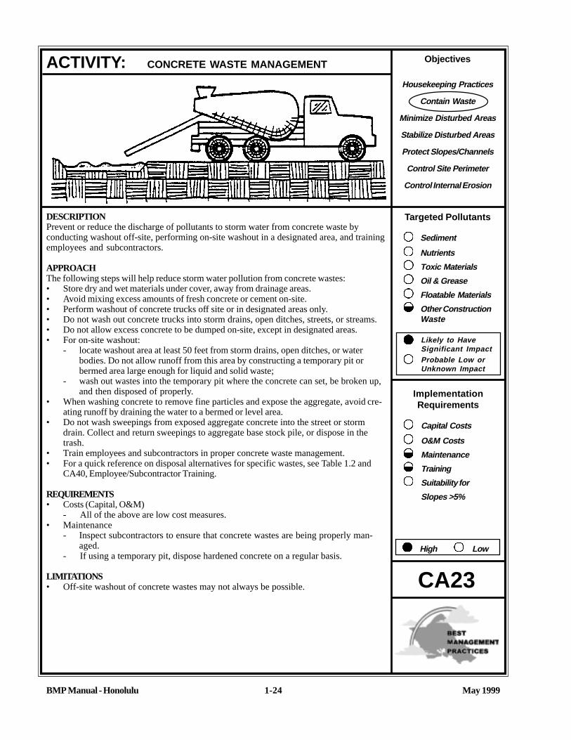
DESCRIPTIONPrevent or reduce the discharge of pollutants to storm water from concrete waste byconducting washout off-site, performing on-site washout in a designated area, and trainingemployees and subcontractors.
APPROACHThe following steps will help reduce storm water pollution from concrete wastes:• Store dry and wet materials under cover, away from drainage areas.• Avoid mixing excess amounts of fresh concrete or cement on-site.• Perform washout of concrete trucks off site or in designated areas only.• Do not wash out concrete trucks into storm drains, open ditches, streets, or streams.• Do not allow excess concrete to be dumped on-site, except in designated areas.• For on-site washout:
- locate washout area at least 50 feet from storm drains, open ditches, or waterbodies. Do not allow runoff from this area by constructing a temporary pit orbermed area large enough for liquid and solid waste;
- wash out wastes into the temporary pit where the concrete can set, be broken up,and then disposed of properly.
• When washing concrete to remove fine particles and expose the aggregate, avoid cre-ating runoff by draining the water to a bermed or level area.
• Do not wash sweepings from exposed aggregate concrete into the street or stormdrain. Collect and return sweepings to aggregate base stock pile, or dispose in thetrash.
• Train employees and subcontractors in proper concrete waste management.• For a quick reference on disposal alternatives for specific wastes, see Table 1.2 and
CA40, Employee/Subcontractor Training.
REQUIREMENTS• Costs (Capital, O&M)
- All of the above are low cost measures.• Maintenance
- Inspect subcontractors to ensure that concrete wastes are being properly man-aged.
- If using a temporary pit, dispose hardened concrete on a regular basis.
LIMITATIONS• Off-site washout of concrete wastes may not always be possible.
ACTIVITY: CONCRETE WASTE MANAGEMENT
CA23

May 1999BMP Manual - Honolulu
CA23
ACTIVITY: CONCRETE WASTE MANAGEMENT (Continue)
1-25
REFERENCESBest Management Practices and Erosion Control Manual for’ Construction Sites; Flood Control District of MaricopaCounty, AZ, July 1992.
Blueprint for a Clean Bay-Construction-Related Industries: Best Management Practices for Storm Water PollutionPrevention; Santa Clara Valley Nonpoint Source Pollution Control Program, 1992.
Storm Water Management for Construction Activities, Developing Pollution Prevention Plans and Best ManagementPractices, EPA 832-R-92005; USEPA, April 1992.

Objectives
Housekeeping Practices
Contain Waste
Minimize Disturbed Areas
Stabilize Disturbed Areas
Protect Slopes/Channels
Control Site Perimeter
Control Internal Erosion
Targeted Pollutants
Sediment
Nutrients
Toxic Materials
Oil & Grease
Floatable Materials
Other ConstructionWaste
Likely to HaveSignificant ImpactProbable Low orUnknown Impact
ImplementationRequirements
Capital Costs
O&M Costs
Maintenance
Training
Suitability for
Slopes >5%
High Low
BMP Manual - Honolulu May 19991-26
DESCRIPTIONPrevent or reduce the discharge of pollutants to storm water from sanitary/septic waste byproviding convenient, well-maintained facilities, and arranging for regular service anddisposal.
APPROACHSanitary or septic wastes should be treated or disposed of in accordance with State, City orother publicly owned treatment system requirements. These requirements may include:• Locate sanitary facilities in a convenient location.• Untreated raw wastewater should never be discharged to ground or buried.• If using an on-site disposal system (OSDS), such as a septic system, comply with State
Department of Health (DOH) requirements.• Temporary sanitary facilities that discharge to the sanitary sewer system should be
properly connected to avoid illicit discharges.• If discharging to the sanitary sewer, contact the local wastewater treatment plant for
their requirements.• Sanitary/septic facilities should be maintained in good working order by a licensed
service.• Arrange for regular waste collection by a licensed hauler before facilities overflow.• For a quick reference on disposal alternatives for specific wastes, see Table 1.2 and
CA40, Employee/Subcontractor Training.
REQUIREMENTS
• Costs (Capital, O&M)- All of the above are low cost measures.
• Maintenance- Inspect facilities regularly.- Arrange for regular waste collection.
LIMITATIONS• There are no major limitations to this best management practice.
REFERENCESBest Management Practices and Erosion Control Manual for Construction Sites; FloodControl District of Maricopa County, AZ, September 1992.
Storm Water Management for Construction Activities, Developing Pollution PreventionPlans and Best Management Practices, EPA 832-R-92005; USEPA, April 1992.
ACTIVITY: SANITARY/SEPTIC WASTE MANAGEMENT
CA24

Objectives
Housekeeping Practices
Contain Waste
Minimize Disturbed Areas
Stabilize Disturbed Areas
Protect Slopes/Channels
Control Site Perimeter
Control Internal Erosion
Targeted Pollutants
Sediment
Nutrients
Toxic Materials
Oil & Grease
Floatable Materials
Other ConstructionWaste
Likely to HaveSignificant ImpactProbable Low orUnknown Impact
ImplementationRequirements
Capital Costs
O&M Costs
Maintenance
Training
Suitability for
Slopes >5%
High Low
BMP Manual - Honolulu May 19991-27
Graphic: North Central Texas COG, 1993
DESCRIPTIONPrevent or reduce the discharge of pollutants to storm water from vehicle and equipmentcleaning by using off-site facilities, washing in designated, contained areas only, eliminat-ing discharges to the storm drain by infiltrating or recycling the wash water, and/or trainingemployees and subcontractors.
APPROACH• Use off-site commercial washing businesses as much as possible. Washing vehicles
and equipment outdoors or in areas where wash water flows onto paved surfaces orinto drainage pathways can pollute storm water. If you wash a large number of vehiclesor pieces of equipment, consider conducting this work at an off-site commercialbusiness. These businesses are better equipped to handle and dispose of the washwaters properly. Performing this work off-site can also be economical by eliminating theneed for a separate washing operation at your site.
• If washing must occur on-site, use designated, bermed wash areas to prevent washwater contact with storm water, streams, rivers, and other water bodies. The wash areacan be sloped for wash water collection and subsequent infiltration into the ground.
• Use as little water as possible to avoid having to install erosion and sediment controlsfor the wash area.
• Use phosphate-free, biodegradable soaps.• Educate employees and subcontractors on pollution prevention measures.• Do not permit steam cleaning on-site. Steam cleaning can generate significant pollutant
concentrations.• For a quick reference on disposal alternatives for specific wastes, see Table 1.2 and
CA40, Employee/Subcontractor Training.
REQUIREMENTS• Costs (Capital, O&M)
- All of the above are low cost measures.• Maintenance
- Minimal, some berm repair may be necessary.
LIMITATIONS• Even phosphate-free, biodegradable soaps have been shown to be toxic to fish before
the soap degrades.• Sending vehicles/equipment off-site should be done in conjunction with ESC24
(Stabilized Construction Entrance).
REFERENCESwisher, RD., 1987. Surfactant Biodegradation, Marcel Decker Corporation
ACTIVITY: VEHICLE AND EQUIPMENT CLEANING
CA30

1-28
DESCRIPTIONPrevent fuel spills and leaks, and reduce their impacts to storm water by using off-sitefacilities, fueling in designated areas only, enclosing or covering stored fuel, implementingspill controls, and training employees and subcontractors.
APPROACH• Use off-site fueling stations as much as possible. Fueling vehicles and equipment
outdoors or in areas where fuel may spill/leak onto paved surfaces or into drainagepathways can pollute storm water. If you fuel a large number of vehicles or pieces ofequipment, consider using an off-site fueling station. These businesses are betterequipped to handle fuel and spills properly. Performing this work off-site can also beeconomical by eliminating the need for a separate fueling area at your site.
• If fueling must occur on-site, use designated areas, located away from drainagecourses, to prevent the runon of storm water and the runoff of spills.
• Discourage “topping-off of fuel tanks.• Always use secondary containment, such as a drain pan or drop cloth, when fueling to
catch spills/leaks.• Place a stockpile of spill cleanup materials where it will be readily accessible.• Use adsorbent materials on small spills rather than hosing down or burying the spill.
Remove the adsorbent materials promptly and dispose of properly.• Carry out all Federal and State requirements regarding stationary above ground
storage tanks.• Avoid mobile fueling of mobile construction equipment around the site; rather,
transport the equipment to designated fueling areas. With the exception of trackedequipment such as bulldozers and perhaps forklifts, most vehicles should be able totravel to a designated area with little lost time.
• Train employees and subcontractors in proper fueling and cleanup procedures.• For a quick reference on disposal alternatives for specific wastes, see Table 1.2 and
CA40, Employee/Subcontractor Training.
REQUIREMENTS• Costs (Capital, O&M)
- All of the above measures are low cost, except for the capital costs of aboveground tanks that meet all local environmental, zoning, and fire codes.
• Maintenance- Keep ample supplies of spill cleanup materials on-site.- Inspect fueling areas and storage tanks on a regular schedule.
LIMITATIONS• Sending vehicles/equipment off-site should be done in conjunction with ESC24
(Stabilized Construction Entrance)
ACTIVITY: VEHICLE AND EQUIPMENT FUELING
CA31
Objectives
Housekeeping Practices
Contain Waste
Minimize Disturbed Areas
Stabilize Disturbed Areas
Protect Slopes/Channels
Control Site Perimeter
Control Internal Erosion
Targeted Pollutants
Sediment
Nutrients
Toxic Materials
Oil & Grease
Floatable Materials
Other ConstructionWaste
Likely to HaveSignificant ImpactProbable Low orUnknown Impact
ImplementationRequirements
Capital Costs
O&M Costs
Maintenance
Training
Suitability for
Slopes >5%
High Low
BMP Manual - Honolulu May 1999

Objectives
Housekeeping Practices
Contain Waste
Minimize Disturbed Areas
Stabilize Disturbed Areas
Protect Slopes/Channels
Control Site Perimeter
Control Internal Erosion
Targeted Pollutants
Sediment
Nutrients
Toxic Materials
Oil & Grease
Floatable Materials
Other ConstructionWaste
Likely to HaveSignificant ImpactProbable Low orUnknown Impact
ImplementationRequirements
Capital Costs
O&M Costs
Maintenance
Training
Suitability for
Slopes >5%
High Low
BMP Manual - Honolulu May 19991-29
Graphic: North Central Texas COG, 1993
DESCRIPTIONPrevent or reduce the discharge of pollutants to storm water from vehicle and equipmentmaintenance by running a “dry site”. This involves using off-site facilities, performing workin designated areas only, providing cover for materials stored outside, checking for leaksand spills, containing and cleaning up spills immediately, and training employees andsubcontractors.
APPROACH• Keep vehicles and equipment clean, don’t allow excessive build-up of oil and grease.• Use off-site repair shops as much as possible. Maintaining vehicles and equipment
outdoors or in areas where vehicle or equipment fluids may spill or leak onto theground can pollute stormwater. If you maintain a large number of vehicles or pieces ofequipment, consider using an off-site repair shop. These businesses are betterequipped to handle vehicle fluids and spills properly. Performing this work off-site canalso be economical by eliminating the need for a separate maintenance area.
• If maintenance must occur on-site, use designated areas, located away from drainagecourses, to prevent the runon of storm water and the runoff of spills.
• Always use secondary containment, such as a drain pan or drop cloth, to catch spillsor leaks when removing or changing fluids.
• Place a stockpile of spill cleanup materials where it will be readily accessible.• Use adsorbent materials on small spills rather than hosing down or burying the spill.
Remove the adsorbent materials promptly and dispose of properly.• Regularly inspect on-site vehicles and equipment for leaks, and repair immediately.• Check incoming vehicles and equipment (including delivery trucks, and employee and
subcontractor vehicles) for leaking oil and fluids. Do not allow leaking vehicles orequipment on-site.
• Segregate and recycle wastes, such as greases, used oil or oil filters, antifreeze,cleaning solutions, automotive batteries, hydraulic, and transmission fluids.
• Train employees and subcontractors in proper maintenance and spill cleanup proce-dures.
• For a quick reference on disposal alternatives for specific wastes, see Table 1.2 andCA40, Employee/Subcontractor Training.
REQUIRMENTS• Costs (Capital, O&M
- All of the above are low cost measures.• Maintenance
- Keep ample supplies of spill cleanup materials on-site.- Inspect maintenance areas on a regular schedule.
ACTIVITY: VEHICLE AND EQUIPMENT MAINTENANCE
CA32

BMP Manual - Honolulu May 1999
CA32
ACTIVITY: VEHICLE AND EQUIPMENT MAINTENANCE (Continue)
1-30
LIMITATIONS• Sending vehicles/equipment off-site should be done in conjunction with ESC24 (Stabilized Construction Entrance).
Outdoor vehicle or equipment maintenance is a potentially significant source of storm water pollution. Activities that cancontaminate storm water include engine repair and service, particularly changing or replacement of fluids, and outdoorequipment storage and parking (dripping engines). For further information on vehicle or equipment servicing, see CA30,Vehicle and Equipment Cleaning, and CA31, Vehicle and Equipment Fueling.
Listed below is further information if you must perform vehicle or equipment maintenance on-site.
Waste ReductionParts are often cleaned using solvents such as trichloroethylene, 1,1,1-trichloroethane, or methylene chloride. Many ofthese parts cleaners are harmful and must be disposed of as a hazardous waste. Reducing the number of solvents makesrecycling easier and reduces hazardous waste management costs. Often, one solvent can perform a job as well as twodifferent solvents. Also, if possible, eliminate or reduce the amount of hazardous materials and waste by substitutingnon-hazardous or less hazardous materials. For example, replace chlorinated organic solvents (1,1,1-trichloroethane,methylene chloride, etc.) with non-chlorinated solvents. Non-chlorinated solvents like kerosene or mineral spirits are lesstoxic end less expensive to dispose of properly. Check list of active ingredients to see whether it contains chlorinatedsolvents. The “chlor” term indicates that the solvent is chlorinated. Also, try substituting a wire brush for solvents toclean parts.
Recycling/DisposalSeparating wastes allows for easier recycling and may reduce disposal costs. Keep hazardous and non-hazardouswastes separate, do not mix used oil and solvents, and keep chlorinated solvents (like 1,1,1-trichloroethane) separatefrom nonchlorinated solvents (like kerosene and mineral spirits). Promptly transfer used fluids to the proper waste orrecycling drums. Don’t leave full drip pans or other open containers lying around.
Oil filters disposed of in trash cans or dumpsters can leak oil and contaminate storm water. Place the oil filter in a funnelover a waste oil recycling drum to drain excess oil before disposal. Oil filters can also be recycled. Ask your oil supplieror recycler about recycling oil filters.
Do not dispose of extra paints and coatings by dumping liquid onto the ground or throwing it into dumpsters. Allowcoatings to dry or harden before disposal into covered dumpsters.
Store cracked batteries in a non-leaking secondary container. Do this with all cracked batteries, even if you think all theacid has drained out. If you drop a battery, treat it as if it is cracked. Put it into the containment area until you are sure itis not leaking.
Do not bury used tires.
REFERENCESBest Management Practices and Erosion Control Manual for Construction Sites; Flood Control District of MaricopaCounty, AZ, September 1992.
Blueprint for a Clean Bay-Construction-Related Industries: Best Management Practices for Storm Water PollutionPrevention; Santa Clara Valley Nonpoint Source Pollution Control Program, 1992.
Coastal Nonpoint Pollution Control Program: Program Development and Approval Guidance, Working Group WorkingPaper; USEPA, April 1992.

Objectives
Housekeeping Practices
Contain Waste
Minimize Disturbed Areas
Stabilize Disturbed Areas
Protect Slopes/Channels
Control Site Perimeter
Control Internal Erosion
BMP Manual - Honolulu May 19991-31
DESCRIPTIONEmployee/subcontractor training, like maintenance or a piece of equipment, is not so much a best management practiceas it is a method by which to implement BMPs. This fact sheet highlights the importance of training and of integratingthe elements of employee/subcontractor training from the individual source controls into a comprehensive trainingprogram as part of a company’s Storm Water Pollution Prevention Plan (SWPPP).
The specific employee/subcontractor training aspects of each of the source controls are highlighted in the individualfact sheets. The focus of this fact sheet is more general, and includes the overall objectives and approach for assuringemployee/subcontractor training in storm water pollution prevention. Accordingly, the organization sheet differssomewhat from the other fact sheets in this chapter.
OBJECTIVESEmployee/subcontractor training should be based on four objectives:• Promote a clear identification and understanding of the problem, including activities with the potential to pollute
storm water,• identify solutions (BMPs);• Promote employee/subcontractor ownership of the problems and the solutions; and• Integrate employee/subcontractor feedback into training and BMP implementation.
APPROACH• Integrate training regarding storm water quality management with existing training programs that may be required for
your business by other regulations such as: the Safety and Health Program (Hawaii Occupational Safety andHealth Standards), the Hazardous Waste Operations and Emergency Response (HAZWOPER) standard (29 CFR1910.120), the Spill Prevention Control and Countermeasure (SPCC) Plan (40 CFR 112), and the Hazardous MaterialsManagement Plan (Business Plan).
• Businesses, particularly smaller ones that may not be regulated by Federal, State, or City regulations, may use theinformation in this Handbook to develop a training program to reduce their potential to pollute storm water.
• Use the quick reference on disposal alternatives (Table 1.2) to train employee/subcontractors in proper and consis-tent methods for disposal.
ACTIVITY: EMPLOYEE/SUBCONTRACTOR TRAINING
CA40
Graphic: City and County of Honolulu, 1998

BMP Manual - Honolulu May 1999
CA40
ACTIVITY: EMPLOYEE/SUBCONTRACTOR TRAINING (Continue)
1-32
• Consider posting the quick reference table around the job site or in the on-site office trailer to reinforce training.• Train employee/subcontractors in standard operating procedures and spill cleanup techniques described in the fact
sheets. Employee/subcontractors trained in spill containment and cleanup should be present during the loading/unloading and handling of materials.
• Personnel who use pesticides should be trained in their use. The State Department of Agriculture, PesticidesBranch, licenses pesticide dealers, certify pesticide applicators, and conduct on-site inspections.
• Proper education of off-site contractors is often overlooked. The conscientious efforts of well trained employee/subcontractors can be lost by unknowing off-site contractors, so make sure they are well informed about what theyare expected to do on-site.

TABLE 1.2 QUICK REFERENCE - DISPOSAL ALTERNATIVES(Adopted from Santa Clara County Nonpoint Source Pollution Control Program - December, 1992)
All of the waste products on this chart are prohibited from discharge to the storm drain system. Use this matrix to decide which alternative disposal strategies to use.ALTERNATIVES ARE LISTED IN PRIORITY ORDER
KEY: POTW - Publicly Owned Treatment Plant, which in most areas is the City & County of Honolulu, Department of Environmental Services.“Dispose to sanitary sewer” means dispose into sink, toilet, or sanitary sewer clean-out connection.“Dispose as trash” means dispose in dumpsters or trash containers for pickup and/or eventual disposal in landfill.“Dispose as hazardous waste” for business/commercial means contract with a hazardous waste hauler to remove and dispose.
DISCHARGE/ACTIVITY BUSINESS/COMMERCIAL Disposal Priorities Approval
General Construction and Painting; Street and Utility MaintenanceExcess Paint (oil- based) 1. Recycle/reuse.
2. If volume is too much to dry, solidify with absorbent material, dispose as solid waste.
Excess Paint (water-based) 1. Recycle/reuse.2. Dry by leaving cans in open air, dispose as solid waste.3. If volume is too much to dry, solidify with absorbent material,
dispose as solid waste.
Paint cleanup (oil-based) Wipe paint out of brushes, then:1. Filter & reuse thinners, solvents.2. Dispose as hazardous waste
Paint cleanup (water-based) Wipe paint out of brushes, then:1. Rinse to sanitary sewer.
Empty paint cans (dry) 1. Remove lids, dispose as solid waste.Paint Stripping (with solvent) 1. Use it up/give it to someone to use for original intended purpose.
2. Separate from non-hazardous wastes (to prevent commingling with recyclable materials.)
3. Dispose as hazardous waste.
Building exterior cleaning (highpressure water)
1. Prevent entry into storm drain and remove offsite2. Wash onto dirt area, spade in3. Collect (e.g. mop up) and discharge to sanitary sewer POTW
BMP Manual - Honolulu 1-33 May 1999
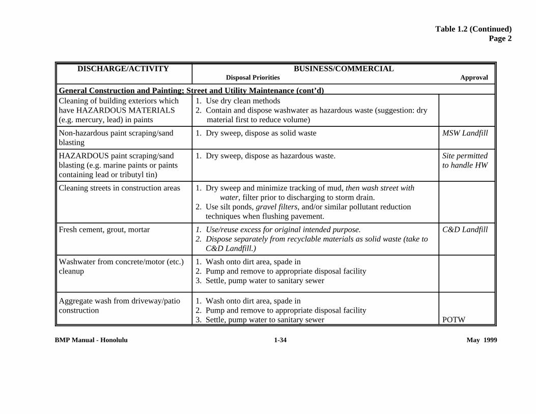
Table 1.2 (Continued)Page 2
DISCHARGE/ACTIVITY BUSINESS/COMMERCIAL Disposal Priorities Approval
General Construction and Painting; Street and Utility Maintenance (cont’d)Cleaning of building exteriors whichhave HAZARDOUS MATERIALS(e.g. mercury, lead) in paints
1. Use dry clean methods2. Contain and dispose washwater as hazardous waste (suggestion: dry
material first to reduce volume)
Non-hazardous paint scraping/sandblasting
1. Dry sweep, dispose as solid waste MSW Landfill
HAZARDOUS paint scraping/sandblasting (e.g. marine paints or paintscontaining lead or tributyl tin)
1. Dry sweep, dispose as hazardous waste. Site permittedto handle HW
Cleaning streets in construction areas 1. Dry sweep and minimize tracking of mud, then wash street with water, filter prior to discharging to storm drain.
2. Use silt ponds, gravel filters, and/or similar pollutant reductiontechniques when flushing pavement.
Fresh cement, grout, mortar 1. Use/reuse excess for original intended purpose.2. Dispose separately from recyclable materials as solid waste (take to
C&D Landfill.)
C&D Landfill
Washwater from concrete/motor (etc.)cleanup
1. Wash onto dirt area, spade in2. Pump and remove to appropriate disposal facility3. Settle, pump water to sanitary sewer
Aggregate wash from driveway/patioconstruction
1. Wash onto dirt area, spade in2. Pump and remove to appropriate disposal facility3. Settle, pump water to sanitary sewer POTW
BMP Manual - Honolulu 1-34 May 1999

Table 1-2 (Continued)Page 3
DISCHARGE/ACTIVITY BUSINESS/COMMERCIAL Disposal Priorities Approval
General Construction and Painting; Street and Utility Maintenance (cont’d)
Rinsewater from concrete trucks 1. Return truck to yard for rinsing into pond or dirt area2. At construction site, wash into pond or dirt area
Non-hazardous construction anddemolition debris
1. Separate debris (e.g., pressure-treated lumber, coated or partially- coated with lead-based paint (LBP), adhesives, asbestos) from recyclable materials (e.g., untreated wood, non-ferrous metals), to the extent feasible at each stage of the construction, or demolition process.
2. Recycle/reuse (e.g., concrete clean of LBP, untreated wood)3. Dispose non-recyclables as solid waste (take to C&D Landfill).
C&D Landfill
Hazardous demolition and constructiondebris (e.g. asbestos)
1. Separate from recyclable materials (to prevent commingling differentwaste types) to the extent feasible each stage of the construction, demolition process.
2. Dispose as hazardous waste
Saw-cut slurry 1. Use dry cutting technique and sweep up residue2. Vacuum slurry and dispose off-site
Construction dewatering 1. Recycle/reuse2. Discharge to sanitary sewer3. As appropriate, treat prior to discharge to storm drain
POTWDOH, DPP
Portable toilet waste 1. Leasing company shall dispose to sanitary sewer at POTW
Leaks from garbage dumpsters 1. Collect, contain leaking material. Eliminate leak, keep covered, return to leasing company for immediate repair.
2. If dumpster is used for liquid waste, use plastic liner
BMP Manual - Honolulu 1-35 May 1999

Table 1.2 (Continued)Page 4
DISCHARGE/ACTIVITY BUSINESS/COMMERCIAL Disposal Priorities Approval
General Construction and Painting; Street and Utility Maintenance (cont’d)Leaks from construction debris bins 1. Insure that bins are used for dry nonhazardous materials only
(Suggestion: Fencing, covering help prevent misuse
Dumpster cleaning water 1. Clean at dumpster’s own facility and discharge waste through grease interceptor to sanitary sewer.
2. Clean on site and discharge through grease interceptor to sanitary sewer.
POTW
POTW
Cleaning driveways, paved areas(Special Focus = Restaurant alleys,Grocery dumpster areas)
1. Sweep and dispose as trash (Dry cleaning only).2. For vehicle leaks, restaurant/grocery alleys, follow this 3-step
process:a. Clean up leaks with rags or absorbents.b. Sweep, use granular absorbent material (cat litter).c. Mop and dispose of mopwater to sanitary sewer (or collect
rinsewater and pump to sanitary sewer)
Steam cleaning of sidewalks, plazas 1. Collect all water and pump to sanitary sewer2. Follow this 3-step process:
a. Clean oil leaks with rages or absorbents.b. Sweep, using granular absorbent material (cat litter)c. Mop and dispose of mopwater to sanitary sewer (or collect
rinsewater and pump to the sanitary sewer).
Potable water/line flushing. Hydranttesting
1. Deactivate chlorine by maximizing time water will travel beforereaching streams or the ocean.
2. Discharge to sanitary sewer.3. Complete dechlorination required before discharge to storm drain.
Permits are required from the City’s Environmental ServicesDepartment and the State DOH
ENV, SWQBranchDOH
BMP Manual - Honolulu 1-36 May 1999

Table 1.2 (Continued)Page 5
DISCHARGE/ACTIVITY BUSINESS/COMMERCIAL Disposal Priorities Approval
Landscape/Garden MaintenancePesticides 1. Use up. Rinse containers use rinsewater as product. Dispose rinsed
containers as trash2. Dispose unused pesticide as hazardous waste
Garden Clippings 1. Separate from “inert fill material,” solid waste and recyclable materials to the extent feasible at each stage of the construction or demolition process.
2. Take to permitted commercial composters (for recycling)
Swimming pool, spa, fountain water(emptying)
1. Do not use metal-based algicides (i.e. Copper Sulfate)2. Recycle/reuse (e.g. irrigation)3. Dechlorinate, check if pH is acceptable, discharge to storm drain
(permit required) ENV, SWQ Branch
Swimming pool, spa filter backwash 1. Reuse for irrigation2. Dispose on dirt area3. Settle, dispose to sanitary sewer
BMP Manual - Honolulu 1-37 May 1999

Table 1.2 (Continued)Page 6
DISCHARGE/ACTIVITY BUSINESS/COMMERCIAL Disposal Priorities Approval
Vehicle WastesUsed motor oil 1. Store in tanks, containers, or other containers that are in good
condition and compatible with the oil, send to permitted recycler via a DOH-permitted transporter.
Antifreeze 1. DO NOT MIX with other hazardous wastes (solvents, pesticides. used oil)
2. Store in tanks, containers, or other containers that are in good condition and compatible with the antifreeze, send to permitted recycler.
3. Dispose as hazardous waste
Other vehicle fluids and solvents 1. DO NOT MIX with hazardous wastes2. Store in tanks, containers, or other containers that are in good
condition and compatible with the fluid, send to permitted recycler.
Automobile batteries 1. Send to auto battery recyclers
Refrigerant 1. Send to an EPA-certified technician who uses EPA-approved recycling/recovery equipment.
Motor home/construction trailer waste 1. Use holding tank. Dispose to sanitary sewer
Vehicle Washing 1. Recycle2. Discharge to sanitary sewer POTW
Mobile Vehicle Washing 1. Collect washwater and discharge to sanitary sewer
Vehicle leaks at Vehicle RepairFacilities
Follow this 3-step process:1. Clean up leaks with rags and absorbents2. Sweep, using granular absorbent material (cat litter)3. Mop and dispose of mop water to sanitary sewer
BMP Manual - Honolulu 1-38 May 1999

Table 1.2 (Continued)Page 7
DISCHARGE/ACTIVITY BUSINESS/COMMERCIAL Disposal Priorities Approval
Other Wastes
Carpet cleaning solutions & othermobile washing services
1. Dispose to sanitary sewer POTW
Roof Drains 1. If roof is contaminated with industrial waste products, discharge to sanitary sewer.
2. If no contamination is present, discharge to storm drain
Cooling water, except for once throughcooling water
1. Recycle/reuse2. Discharge to sanitary sewer POTW
Pumped groundwater,infiltration/foundation drainage(contaminated)
1. Recycle/reuse (landscaping, etc.)2. Treat if necessary; discharge to sanitary sewer3. Treat and discharge to storm drain
POTWENV, SWQBranch
Kitchen Grease 1. Provide secondary containment, collect, and send to DOH-permittedprocessor or recycler.
2. NOTE: prior to transport, check with the City and County if POTWis an option, as they may not accept untreated grease.
POTW
Restaurant cleaning of floor mats,exhaust filters, etc.
1. Clean inside building with discharge through grease trap to sanitary sewer
2. Clean outside in container or bermed area with discharge to sanitary sewer
Clean-up wastewater from sewerbackup
1. Follow this procedure:a. Block storm drain, contain, collect, and return spilled material
to the sanitary sewer.b. Block storm drain, rinse remaining material to collection point
and pump to sanitary sewer (No rinsewater may flow to storm drain).
BMP Manual - Honolulu 1-39 May 1999

INTRODUCTION
BMP Manual - Honolulu 2-1 May 1999
BMPs for Erosion andSedimentation Control
Site Planning ConsiderationsESC1 SchedulingESC2 Preservation of Existing
VegetationESC3 Location of Potential Sources of
Sediment
Vegetative StabilizationESC10 Seeding and PlantingESC11 Mulching
Physical StabilizationESC20 Geotextiles and MatsESC21 Dust ControlESC22 Temporary Stream CrossingESC23 Construction Road StabilizationESC24 Stabilized Construction EntranceESC25 Protection of Stockpiles
Diversion of RunoffESC30 Earth DikeESC31 Temporary Drains and SwalesESC32 Slope Drain
Velocity ReductionESC40 Outlet ProtectionESC41 Check DamsESC42 Slope Roughening/Terracing
Sediment Trapping/FilteringESC50 Silt FenceESC52 Sand Bag BarrierESC53 Brush or Rock FilterESC54 Storm Drain Inlet ProtectionESC55 Sediment TrapESC56 Sediment Basin
2. BMPs FOR EROSION AND SEDIMENTATION CONTROL
This chapterdescribes specificBest ManagementPractices (BMPs)
for common construction activities thatresult in erosion of the construction site andthe generation of sediment which impactswaterways and off-site property. Thischapter will provide you with the BMPs forerosion and sediment control that best fityour site's needs.
Each fact sheet contains a cover sheet with:
• A description of the BMP• Suitable Applications• Installation/Application Criteria• Requirements
- Costs, including capital costs, andoperations and maintenance (O&M)
- Maintenance (includingadministrative and staffing)
• Limitations
The side bar presents information on whichBMP objective applies, targetedconstituents, and an indication of the levelof effort and costs to implement, Theremainder of the fact sheet provides furtherinformation on some or all of these topics,and provides references for additionalguidelines.
Keep in mind that these controls must alsobe able to safely contain or convey stormslarger than the design storm for erosion andsediment control.
These BMP fact sheets are suitable forinclusion in many SWPPPs for erosion andsedimentation control. They may be used to
supplement and provide details for erosionand sedimentation controls shown on theproject site map.

BMP Manual - Honolulu 2-2 May, 1999
In all cases, however, State and City erosionand sedimentation criteria and standardssupercede the suggested criteria on thesefact sheets. Refer to the “Rules Relating toSoil Erosion Standards and Guidelines,”April 1999, for additional information.

TABLE 2.1 EROSION AND SEDIMENT CONTROL AND BMP OBJECTIVES
BMP CATEGORY
BMP OBJECTIVESPRACTICE
GOODHOUSE-
KEEPINGCONTAIN
WASTE
MINIMIZEDISTURBED
AREA
STABILIZEDISTURBED
AREA
PROTECTSLOPES
ANDCHANNELS
CONTROLSITE
PERIMETER
CONTROLINTERNALEROSION
Site Planning Considerations
ESC1 Scheduling UU UU UU UU UU UU UUESC2 Preservation of Existing Vegetation UU UU UU UUESC3 Location of Potential Sources of
Sediment UU UU
Vegetative Stabilization
ESC10 Seeding and Planting UU UUESC11 Mulching UU UU
Physical Stabilization
ESC20 Geotextiles and Mats U UESC21 Dust Control UU U U UESC22 Temporary Stream Crossing UU U U UESC23 Construction Road Stabilization U UU U UESC24 Stabilized Construction Entrance UU UU UU UESC25 Protection of Stockpiles UU U
Diversion Runoff
ESC30 Earth Dike UU UU UU UUESC31 Temporary Drains and Swales UU UU UUESC33 Slope Drain UU
Velocity Reduction
ESC40 Outlet Protection UUESC41 Check Dams (see ESC 53 also) UUESC42 Slope Roughening/Terracing UU UU
BMP Manual - Honolulu 2-3 May 1999

BMP CATEGORY
BMP OBJECTIVES
PRACTICEGOOD
HOUSE-KEEPING
CONTAINWASTE
MINIMIZEDISTURBED
AREA
STABILIZEDISTURBED
AREA
PROTECTSLOPES
ANDCHANNELS
CONTROLSITE
PERIMETER
CONTROLINTERNALEROSION
Sediment Trapping/Filtering
ESC50 Silt Fence UU UUESC52 Sand Bag Barrier UU UU UESC53 Brush or Rock Filter UU UU UESC54 Storm Drain Inlet Protection U UESC55 Sediment Trap UESC56 Sediment Basin U
BMP Manual - Honolulu 2-4 May 1999

Objectives
Housekeeping Practices
Contain Waste
Minimize Disturbed Areas
Stabilize Disturbed Areas
Protect Slopes/Channels
Control Site Perimeter
Control Internal Erosion
Targeted Pollutants
Sediment
Nutrients
Toxic Materials
Oil & Grease
Floatable Materials
Other ConstructionWaste
Likely to HaveSignificant ImpactProbable Low orUnknown Impact
ImplementationRequirements
Capital Costs
O&M Costs
Maintenance
Training
Suitability for
Slopes >5%
High Low
May 1999BMP Manual - Honolulu 2-5
DESCRIPTIONSequencing the construction project to reduce the amount and duration of soil exposed toerosion by wind, rain, runoff, and vehicle tracking.
SUITABLE APPLICATIONSProper sequencing of construction activities to reduce erosion potential should beincorporated into the schedule of every construction project. Use of other, more costly yetless effective, erosion and sedimentation controls, may often be reduced through properconstruction sequencing.
APPROACH• Project design considerations: Design project to integrate into existing land contours.
Significant regrading of a site will require more costly erosion and sedimentationcontrol measures and may require that on-site drainage facilities be installed.
• Incorporate existing, natural areas: Inventory and evaluate the existing site terrain andvegetation. Disturbance of highly erosive natural areas (e.g., steep, unstable slopeareas, watercourses) should be minimized, while protecting other areas may enhancesite aesthetics. Construction should not disturb these areas (see ESC2).
• Avoid rainy periods: Schedule major grading operations during dry months. Allowenough time before rainfall begins to stabilize the soil with vegetation or physicalmeans (see ESC10 to 24) or to install temporary sediment trapping devices (see ESC50to 56).
• Practice erosion and sediment control year round: Erosion may be caused during dryseasons by “freak” rainfall, wind and vehicle tracking. Therefore, keep the site stabi-lized year-round, and retain wet season sediment trapping devices.
• Minimize soil exposed at one time: Schedule projects to disturb only small portions ofthe site at any one time. Complete grading as soon as possible. Immediately stabilizethe disturbed portion before grading the next portion. Practice staged seeding—revegetate cut and fill slopes as the work progresses.
• Trenching: Close and stabilize open trenches as soon as possible. Sequence trenchingprojects so that most open portions of the trench are closed before new trenching isbegun.
REQUIREMENTS• Cost
- Construction scheduling to reduce erosion may increase other construction costsdue to reduced economies of scale in performing site grading. The cost-effectiveness of scheduling techniques should be compared with the other, lesseffective erosion and sedimentation controls to achieve a cost-effective balance.
BMP: SCHEDULING
ESC1

May 1999BMP Manual - Honolulu
ESC1
BMP: SCHEDULING (Continue)
2-6
LIMITATIONSThere are no significant limitations to the use of this BMP.
REFERENCESBest Management Practices and Erosion Control Manual for Construction Sites, Flood Control District of MaricopaCounty, Arizona - 1992.
Erosion and Sediment Control Guidelines for Developing Areas in Texas, U.S. Department of Agriculture, Soil Conserva-tion Service, Fort Worth, Texas - 1976.
Storm Water Management for Construction Activites. Developing Pollution Prevention Plans and Best ManagementPractices, U.S. Environmental Protection Agency, Office of Water (EPA 832-R-92-005) - September, 1992.
Virginia Erosion and Sediment Control Handbook, Third Edition, Virginia Department of Conservation and Recreation,Division of Soil and Water Conservation - 1992.
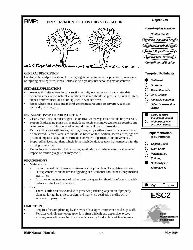
Objectives
Housekeeping Practices
Contain Waste
Minimize Disturbed Areas
Stabilize Disturbed Areas
Protect Slopes/Channels
Control Site Perimeter
Control Internal Erosion
Targeted Pollutants
Sediment
Nutrients
Toxic Materials
Oil & Grease
Floatable Materials
Other ConstructionWaste
Likely to HaveSignificant ImpactProbable Low orUnknown Impact
ImplementationRequirements
Capital Costs
O&M Costs
Maintenance
Training
Suitability for
Slopes >5%
High Low
May 1999BMP Manual - Honolulu
ESC2
2-7
GENERAL DESCRIPTIONCarefully planned preservation of existing vegetation minimizes the potential of removingor injuring existing trees, vines, shrubs and/or grasses that serve as erosion controls.
SUITABLE APPLICATIONS• Areas within site where no construction activity occurs, or occurs at a later date.• Sensitive areas where natural vegetation exist and should be preserved, such as: steep
slopes, watercourses, and building sites in wooded areas.• Areas where local, state and federal government requires preservation, such as:
wetlands, marshes, etc.
INSTALLATION/APPLICATION CRITERIA• Clearly mark, flag or fence vegetation or areas where vegetation should be preserved.• Prepare landscaping plans which include as much existing vegetation as possible and
state proper care of this vegetation both during and after construction.• Define and protect with berms, fencing, signs, etc., a setback area from vegetation to
be preserved. Setback area size should be based on the location, species, size, age andpotential impact of adjacent construction activities or permanent improvements.
• Proposed landscaping plans which do not include plant species that compete with theexisting vegetation.
• Do not locate construction traffic routes, spoil piles, etc., where significant adverseimpact on existing vegetation may occur.
REQUIREMENTS• Maintenance
- Inspection and maintenance requirements for protection of vegetation are low.- During construction the limits of grading or disturbance should be clearly marked
at all times.- Irrigation or maintenance of native trees or vegetation should conform to specifi-
cations on the Landscape Plan.• Cost
- There is little cost associated with preserving existing vegetation if properlyplanned during the project design, and may yield aesthetic benefits whichenhance property values.
LIMITATIONS• Requires forward planning by the owner/developer, contractor and design staff.• For sites with diverse topography, it is often difficult and expensive to save
existing trees while grading the site satisfactorily for the planned development.
BMP: PRESERVATION OF EXISTING VEGETATION

May 1999BMP Manual - Honolulu
The best way to prevent excessive erosion is to not disturb the land. On a construction site, where extensive landdisturbance is necessary, a reasonable BMP would be to not disturb land in sensitive areas of the site which need not bealtered for the project to be viable (e.g., natural watercourses, steep slopes), and to design the site to incorporateparticularly unique or desirable existing vegetation into the site landscaping plan. Clearly marking and leaving a bufferarea around these unique areas will both help to preserve these areas as well as take advantage of natural erosionprevention and sediment trapping in naturally vegetated areas.
Existing vegetation to be preserved on the site must be protected from mechanical and other injury while the land isbeing developed. The purpose of protecting existing vegetation is to insure the survival of desirable vegetation forshade, beautification, and erosion protection. Mature vegetation has extensive root systems that help to hold soil inplace, thus reducing erosion. Also, vegetation helps to keep soil from drying rapidly and becoming susceptible toerosion. To effectively save existing vegetation, no disturbances of any kind should be allowed within a defined areaaround the vegetation. For trees, no construction activity should occur within the drip line of the tree.
The following criteria may be used for deciding which vegetation will remain on the site:• Aesthetic values: Consideration should be given to foliage, flowering habits, bark and crown characteristics (for
trees).• Freedom from disease and rot.• Life span of trees: Short-lived trees need not be preserved.• Environmental values: Habitat; screening; and buffers.• Sudden exposure: Save vegetation which grows in direct sunlight and is able to withstand radiated beat from
proposed buildings and pavement.• Space needed: Sufficient space must be provided between the vegetation and any structures, electric and telephone
lines, water and sewer lines, driveways and streets. Mark trees and shrubs with bright paint or ribbon so there is nodoubt as to which trees and shrubs are to be left and protected from damage during construction.
Saving existing vegetation and mature trees on-site, beautifies the area and may save money by reducing new landscap-ing requirements. Mature trees also increase property values and satisfy consumer aesthetic needs.
Preserving and protecting existing vegetation can often result in more stable soil conditions during construction. Carefulsite planning and identification of plantings to preserve can provide erosion and sedimentation controls during con-struction, and contribute to the aesthetics of the development. Provisions to protect the tree and its root system duringconstruction must be specified in the project plans, and an area must be provided where the soil stability may not bedisturbed. No grading or construction storage within the tree drip line is allowed.
Installation/ApplicationBuilding sites may be planned to integrate existing vegetation and trees. Construction impacts must be considered.Trench width for pipe construction projects and the location of permanent structures, such as buildings, needs to beconsidered when preserving existing vegetation, including mature trees and their root system. Native vegetation shouldbe preserved since it is able to adapt to the climate. The USDA National Resources Conservation Service (NRCS) shouldbe contacted about existing vegetation. Mature trees are generally preferable to newly planted trees because of thegreater soil stabilization provided by the extensive root system of a mature tree.
ADDITIONAL INFORMATION: PRESERVATION OF EXISTING VEGETATION
2-8
ESC2

May 1999BMP Manual - Honolulu
ADDITIONAL INFORMATION: PRESERVATION OF EXISITING VEGETATION
ESC2
2-9
Methods for protecting existing vegetation and trees:• Stake off root system limits (drip line of tree). Some counties limit construction within 5 feet of the tree drip line.• Fence off the area to be preserved or along the tree drip line.• Flag or mark trees to remain in place.• Tree wells and retaining walls (permanent) help preserve existing vegetation, but must be large enough to protect the
root system (see below).• Where grading under trees is necessary, excavation and fill should be limited to one foot within the drip lines.
REFERENCESBest Management Practices and Erosion Control Manual for Construction Sites, Flood Control District of MaricopaCounty, Arizona, September 1992.
County of Sacramento Tree Preservation Ordinance - September 1981.
Stormwater Management Water for the Puget Sound Basin, Washington State Department of Ecology, The TechnicalManual - February 1992, Publication # 91-75.
Water Quality Management Plan for the Lake Tahoe Region, Volume II Handbook of Management Practices, TahoeRegional Planning Agency - November 1988.
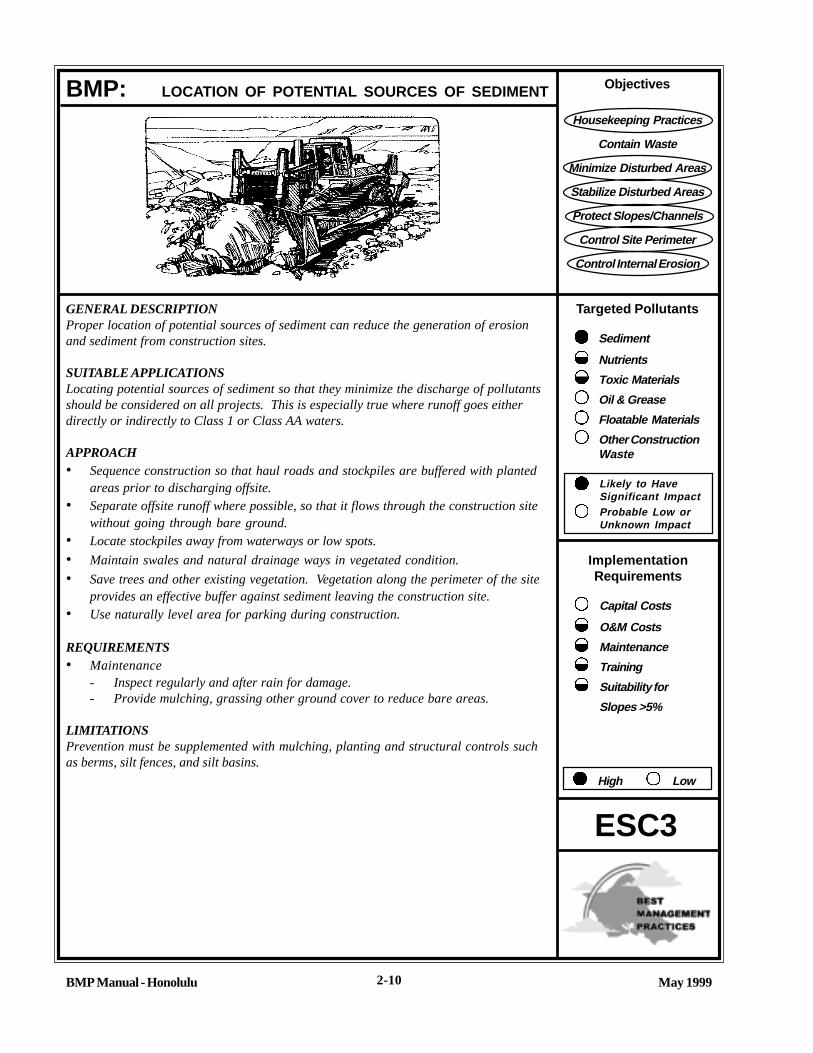
Objectives
Housekeeping Practices
Contain Waste
Minimize Disturbed Areas
Stabilize Disturbed Areas
Protect Slopes/Channels
Control Site Perimeter
Control Internal Erosion
Targeted Pollutants
Sediment
Nutrients
Toxic Materials
Oil & Grease
Floatable Materials
Other ConstructionWaste
Likely to HaveSignificant ImpactProbable Low orUnknown Impact
ImplementationRequirements
Capital Costs
O&M Costs
Maintenance
Training
Suitability for
Slopes >5%
High Low
BMP Manual - Honolulu May 1999
BMP: LOCATION OF POTENTIAL SOURCES OF SEDIMENT
GENERAL DESCRIPTIONProper location of potential sources of sediment can reduce the generation of erosionand sediment from construction sites.
SUITABLE APPLICATIONSLocating potential sources of sediment so that they minimize the discharge of pollutantsshould be considered on all projects. This is especially true where runoff goes eitherdirectly or indirectly to Class 1 or Class AA waters.
APPROACH• Sequence construction so that haul roads and stockpiles are buffered with planted
areas prior to discharging offsite.• Separate offsite runoff where possible, so that it flows through the construction site
without going through bare ground.• Locate stockpiles away from waterways or low spots.
• Maintain swales and natural drainage ways in vegetated condition.
• Save trees and other existing vegetation. Vegetation along the perimeter of the siteprovides an effective buffer against sediment leaving the construction site.
• Use naturally level area for parking during construction.
REQUIREMENTS• Maintenance
- Inspect regularly and after rain for damage.- Provide mulching, grassing other ground cover to reduce bare areas.
LIMITATIONSPrevention must be supplemented with mulching, planting and structural controls suchas berms, silt fences, and silt basins.
ESC3
2-10
May 1999BMP Manual - Honolulu
REFERENCESErosion and Sediment Control Guide for Hawaii, March 1981, USDA Soil Conservation Service.
Rules Relating to Soil Erosion Standards and Guidelines, April 1999, Department of Planning and Permitting, Cityand County of Honolulu.
Storm Water Management for Construction Activities: Developing Pollution Prevention Plans and Best ManagementPractices, September 1992, U.S. Environmental Protection Agency.
California Storm Water Best Management Best Management Practice Handbooks, Construction Activity Best Manage-ment Practice Handbook, March 1993, Camp Dresser & McKee et. al. For the California Storm Water Quality TaskForce.
Planning and Design Manual for the Control and Erosion, Sediment, and Stormwater, A Cooperative Effort by: USDANatural Resources Conservation Service, Mississippi Department of Environmental Quality, and the Mississippi Soil& Water Conservation Commission.
BMP: LOCATION OF POTENTIAL SOURCES OF SEDIMENT (Continue)
ESC3
2-11

Objectives
Housekeeping Practices
Contain Waste
Minimize Disturbed Areas
Stabilize Disturbed Areas
Protect Slopes/Channels
Control Site Perimeter
Control Internal Erosion
Targeted Pollutants
Sediment
Nutrients
Toxic Materials
Oil & Grease
Floatable Materials
Other ConstructionWaste
Likely to HaveSignificant ImpactProbable Low orUnknown Impact
ImplementationRequirements
Capital Costs
O&M Costs
Maintenance
Training
Suitability for
Slopes >5%
High Low
BMP Manual - Honolulu May 1999
ESC10
2-12
GENERAL DESCRIPTIONSeeding of grasses and plantings of trees, shrubs, vines and ground covers providelongterm stabilization of soil. In some areas, with suitable climates, grasses can be plantedfor temporary stabilization.
SUITABLE APPLICATIONS• Appropriate for site stabilization both during construction and post-construction.• Any graded/cleared areas where construction activities have ceased.• Open space cut and fill areas.• Steep slopes.• Spoil piles.• Vegetated swales.• Landscape corridors.• Stream banks.
INSTALLATION/APPLICATION CRITERIAType of vegetation, site and seedbed preparation, planting time, fertilization and waterrequirements should be considered for each application.
Grasses:• Ground preparation: fertilize and mechanically stabilize the soil.• Tolerant of short-term temperature extremes and waterlogged soil conditions.• Appropriate soil conditions: shallow soil base, good drainage, slope 2:1 or flatter.• Develop well and quickly from seeds.• Mowing, irrigating, and fertilizing are vital for promoting vigorous grass, growth.
Trees and Shrubs:• Selection Criteria: vigor, species, size, shape & wildlife food source.• Soil conditions: select species appropriate for soil, drainage & acidity.• Other Factors: wind/exposure, and irrigation needs.
Vines and Ground Covers:• Ground preparation: lime and fertilizer preparation.• Use proper seeding rates.• Appropriate soil conditions: drainage, acidity, slopes.• Generally avoid species requiring irrigation.
BMP: SEEDING AND PLANTING

May 1999BMP Manual - Honolulu
BMP: PLANTING AND SEEDING (Continue)
2-13
ESC10
REQUIREMENTS• Maintenance
- Shrubs and trees must be adequately watered and fertilized and if needed pruned.- Grasses may need to be watered and mowed.
• Cost: Average annual cost for installation and maintenance (2- year useful life, source: EPA, 1992)- Seeding: $300 per acre, appropriate for flat slopes and stable soils.- Seeding with Mulching: $1,100 per acre, appropriate for moderate to steep slopes and/or erosive soils.- Trees, shrubs, vines, and ground cover: Cost, applicability based on species used and terrain features.
LIMITATIONS• Permanent and temporary vegetation may not be appropriate in dry periods without irrigation.• Fertilizer requirements may have potential to create storm water pollution if improperly applied.

May 1999BMP Manual - Honolulu
ADDITIONAL INFORMATION: SEEDING AND PLANTING
ESC10
2-14
Permanent seeding of grasses, sodding, and planting of trees, shrubs, vines and ground covers can provide long-termstabilization of soil. Permanent seeding and planting contributes to long-term site aesthetics and helps reduce erosion byreducing the velocity of runoff, allowing infiltration to occur, filtering sediments, and by holding soil particles in place.
Seeding and planting should be applied as soon as final grading is done to all graded and cleared areas of the construc-tion site where plant cover is ultimately desired. For example, vegetation may be established along landscaped corridorsand buffer zones where they may act as filter strips (see TC6 in Chapter 5 of the California Municipal BMP Handbook).Additionally, vegetated swales, steep and/or arid/or rocky slopes and stream banks can also serve as appropriate areasfor seeding and plantings.
Installation/Application CriteriaApplication of appropriate vegetation must consider: the seedbed or plantbed, proper seasonal planting times, waterrequirements fertilizer requirements and availability of the selected vegetation within the project’s region. Permanentplantings during the construction stage of projects require careful coordination between the local agency inspectors,project managers, construction managers, and landscape contractor. Protocols for coordination and implementationprocedures regarding site access, construction staging, and short- and long-term planting areas should be developedprior to the construction bid process. Where possible, these protocols should be established by and remain the respon-sibility of the site owner.
Because of the many available types of plants and ground covers and because site conditions and land use vary sowidely, a set of general guidelines is included for installation/application of grasses, trees and shrubs, vines and groundcovers. However, the National Resources Conservation Service (NRCS), agricultural extension or other resources shouldbe consulted on appropriate species, planting requirements, and maintenance needs for your climate and soils.
GrassesGrasses, depending on the type, provide short-term soil stabilization during construction or can serve as long- term/permanent soil stabilization for disturbed areas. In general, grasses provide low maintenance to areas that have beencleared, graded and mechanically stabilized.
Selection:The selection of the grass type is determined by the climate, irrigation, mowing frequency, maintenance effort andsoilbed conditions. Although grasses provide quick germination and rapid growth, they also have a shallow root systemand are not as effective in stabilizing deep soils, where trees, shrubs and deep rooted ground covers may be moreappropriate. Specific seed mix and/or varieties for each site should be provided by an approved/qualified plant materialsspecialist.
May 1999BMP Manual - Honolulu
ESC10
ADDITIONAL INFORMATION: SEEDING AND PLANTING
2-15
Planting:The following steps should be followed to ensure established growth:1. Select the proper grass for the site.2. Prepare the seedbed; soil should be fertilized and contain good topsoil or soil at least a 2:1 or flatter
slope.3. Initial irrigation will be required often for most grasses, with follow-up irrigation and fertilization as
needed. Mulching may be required in dry climates or during drought years.
Trees & Shrubs
Selection:Trees and shrubs, when properly selected, are low maintenance plantings that stabilize adjacent soils,moderate the adjacent temperatures, filter air pollutants, and serve as a barrier to wind. Some desirablecharacteristics to consider in selecting trees and shrubs include: vigor, species, age, size and shape, anduse as a wildlife food source and habitat.
Trees and shrubs to be saved should be clearly marked so that no construction activity will take placewithin the dripline of the plant. The sites for new plantings should be evaluated. Consider the prior use ofthe land: adverse soil conditions such as poor drainage or acidity; exposure to wind; temperature ex-tremes; location of utilities, paved areas, and security lighting and traffic problems.
Transplanting:Preparation - Proper digging of a tree/shrub includes the conservation of as much of the root system aspossible. Soil adhering to the roots should be damp when the tree is dug, and kept moist until re-planting.The soil ball should be 12 inches in diameter for each inch of diameter of the trunk.
Site preparation - Refer to landscape plans and specifications for site and soil preparation, and for abilityto coordinate construction strategy with permanent vegetation.
Supporting the trunk - Many newly planted trees/shrubs need artificial support to prevent excessiveswaying.
Watering - Soil around the tree should be thoroughly watered after the tree is set in place. When the soilbecomes dry, the tree should be watered deeply, but not often. Mulching around the base of the tree ishelpful in preventing roots from drying out.
Vines & Ground Covers
Selection:Vines, ground covers, and low growing plants, that can quickly spread, come in many types, colors, andgrowth habits. Some are suitable only as part of a small maintained landscape area, while some canstabilize large areas with little maintenance. Flowers, which provide little long-term erosion control maybe planted to add color and varietal appearances.

May 1999BMP Manual - Honolulu
ESC10
ADDITIONAL INFORMATION: SEEDING AND PLANTING
Caution should be exercised in the non-native vegetation because of impacts to native vegetation on adjacent lands. Forexample, species that may be planted at the construction site can quickly spread and compete with originally undis-turbed vegetation. In addition to stabilizing disturbed soil, vines and ground covers can perform the following func-tions:
1. Provide attractive cover that does not need mowing.2. Help to define traffic areas and control pedestrian movement.
Site Preparation:Ground covers are plants that naturally grow very close together, causing severe competition for space nutrients andwater. Sod for ground covers should be well prepared. The entire area should be spaded, disced, or rototilled to a depthof six to eight inches. Two to three inches of organic material, such as good topsoil or peat, should be spread over theentire area.
Planting:The following steps will help ensure good plant growth.
1. Make the plantings following the contours of the land.2. Dig the holes 1/3 larger than the plant root ball.3. Know what depth to place the plants.4. Use good topsoil or soil mixture with a lot of organic matter.5. Fill hole 1/3 to 1/2 full, shake plants to settle soil among roots, then water.6. Leave saucer-shaped depression around the plant to hold water.7. Water thoroughly and regularly.8. Space plants according to the type of plant and the extent of covering desired.
Materials:There are many different species of vines and ground covers from which to choose, but care must be taken in theirselection. It is essential to select planting materials suited to both the intended use and specific site characteristics.Additional information can be obtained from local nurserymen, landscape architects, and extension agents. An approvedlow water use plant list may be obtained from the Board of Water Supply (BWS), or Natural Resources ConservationService.
RequirementsMaintenance
General requirements include:• Grass maintenance should be minimal to none. Irrigation and regular fertilizing may be required for some types of
grasses. Mowing is only required in areas where aesthetics or fire hazards are a concern.• Young trees should receive an inch of water each week for the first two years after planting. The tree should be
watered deeply, but not more often than once per week• Transplanted trees, should be fertilized on an annual basis.• Proper pruning, watering, and application of fertilizer is necessary to maintain healthy and vigorous shrubs. A
heavy layer of mulch applied around the shrubs reduces weeds and retains moisture.• Trim old growth as needed to improve the appearance of ground covers. Most covers need once-trimming to
promote growth.
2-16
May 1999BMP Manual - Honolulu
ESC10
ADDITIONAL INFORMATION: SEEDING AND PLANTING
2-17
Limitations• Construction activities are likely to injure or kill trees unless adequate protective measures are taken.
Direct contact by equipment is the most obvious problem, but damage is also caused by root stressfrom filling, excavation, or compacting too close to trees.
• Temporary seeding can only be viable when adequate time is available for plants to grow andestablish.
• Over fertilizing of plants may cause pollution of storm water runoff.• Irrigation source and supply may be limiting.
REFERENCESBest Management Practices and Erosion Control Manual for Construction Sites, Flood Control District ofMaricopa County, September 1992.
“Draft - Sedimentation and Erosion Control, An Inventory of Current Practices”, U.S.E.P.A., April, 1990.
Guides for Erosion and Sediment Controls in California, USDA Soils Conservation Service - January 1991.
Kiowa Engineering, Interim Erosion and Sedimentation Control for Construction Activities, UrbanDrainage and Flood Control District, Denver, Colorado.
Manual of Standards of Erosion and Sediment Control Measures, Association of Bay Area Governments,Jun 1981.
Proposed Guidance Specifying Management Measures for Sources of Nonpoint Pollution in CoastalWaters, Work Group Working Paper, USEPA, April, 1992.
Stormwater Management Water for the Puget Sound Basin, Washington State Department of Ecology,The Technical Manual - February 1992, Publication # 91-75.
Water Quality Management Plan for the Lake Tahoe Region, Volume II Handbook of ManagementPractices. Tahoe Regional Planning Agency - November 1988.
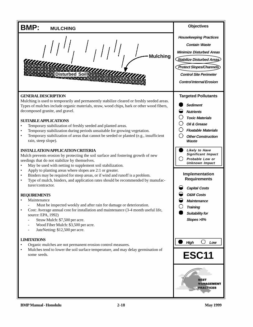
Objectives
Housekeeping Practices
Contain Waste
Minimize Disturbed Areas
Stabilize Disturbed Areas
Protect Slopes/Channels
Control Site Perimeter
Control Internal Erosion
Targeted Pollutants
Sediment
Nutrients
Toxic Materials
Oil & Grease
Floatable Materials
Other ConstructionWaste
Likely to HaveSignificant ImpactProbable Low orUnknown Impact
ImplementationRequirements
Capital Costs
O&M Costs
Maintenance
Training
Suitability for
Slopes >5%
High Low
BMP Manual - Honolulu May 19992-18
GENERAL DESCRIPTIONMulching is used to temporarily and permanently stabilize cleared or freshly seeded areas.Types of mulches include organic materials, straw, wood chips, bark or other wood fibers,decomposed granite, and gravel.
SUITABLE APPLICATIONS• Temporary stabilization of freshly seeded and planted areas.• Temporary stabilization during periods unsuitable for growing vegetation.• Temporary stabilization of areas that cannot be seeded or planted (e.g., insufficient
rain, steep slope).
INSTALLATION/APPLICATION CRITERIAMulch prevents erosion by protecting the soil surface and fostering growth of newseedings that do not stabilize by themselves.• May be used with netting to supplement soil stabilization.• Apply to planting areas where slopes are 2:1 or greater.• Binders may be required for steep areas, or if wind and runoff is a problem.• Type of mulch, binders, and application rates should be recommended by manufac-
turer/contractor.
REQUIREMENTS• Maintenance
- Must be inspected weekly and after rain for damage or deterioration.• Cost: Average annual cost for installation and maintenance (3-4 month useful life,
source: EPA, 1992)- Straw Mulch: $7,500 per acre.- Wood Fiber Mulch: $3,500 per acre.- JuteNetting: $12,500 per acre.
LIMITATIONS• Organic mulches are not permanent erosion control measures.• Mulches tend to lower the soil surface temperature, and may delay germination of
some seeds.
BMP: MULCHING
ESC11
Mulching
Disturbed Soil

May 1999BMP Manual - Honolulu
Mulching protects the soil from rainfall impact; increases infiltration; conserves moisture around trees, shrubs andseedings; prevents compaction and cracking of soil; and aids plant growth for seedings and plantings by holding theseeds, fertilizers and topsoil in place until growth occurs. Mulches include organic materials, straw, wood chips, bark orother wood fibers, decomposed granite and gravel. A variety of nettings or mats of organic or non-organic materials andchemical sod stabilization are practices that may be used conjunctively with mulching.
Mulching may be applied to all graded and cleared areas of the construction site:• Areas which have been permanently seeded to assist in retaining moisture, and to hold seedings;• Areas which need temporary soil surface protection because seeding cannot occur due to the season;• Areas between trees, shrubs and certain ground covers;• Areas where climatic conditions require a soil moisture retention aid to avoid cracking of the soil and associated
compaction, and require soil temperature modification.
Installation/Application CriteriaOnly a set of general guidelines is included for application and installation of mulching on disturbed lands because ofthe various climates, soil conditions and land uses in California. Installation of mulch consists of furnishing all materials,preparing the soil surface and applying the mulch to all soil surface areas designated on the project plans or establishedby the site engineer.
MaterialsOrganic mulch materials, such as straw, wood chips, bark and wood fiber, have been found to be most effective where re-vegetation will be provided by reseeding. The choice of mulch should be based on the size of the area, site slopes,surface conditions such as hardness and moisture; weed growth and availability of mulch materials.
Wood Fiber Mulches: Wood fiber mulches consist of specially prepared wood fiber processed to contain no growthgermination inhibiting factors. The mulch should be from virgin wood, and be manufactured and processed so the fiberswill remain in uniform suspension in water under agitation to form a homogenous slurry. The fiber lengths should be aslong as possible to increase the effectiveness for erosion control. Wood fiber mulching should not be used in areas ofextremely hot summer and late fan seasons because of fire danger. When used as a tackifier with straw mulch, wood fibermulches are good for steep slopes and severe climates. The California Office of the Natural Resources ConservationService (NRCS) recommends a non-toxic mulch green dye be used to provide a visual aid in metering applications.
Wood Chips and Bark Chips: Wood and bark chips are suitable for application in landscaped areas that will not beclosely mowed. Wood chips do not require tacking, but do require nitrogen treatment (12 pounds/ton) to preventnutrient deficiency. Bark chips do not require additional nitrogen fertilizer. When the wood source is near the project site,wood and bark chips can be very inexpensive. Caution must be used in areas of steep slopes, since both wood and barkchips tend to wash down slopes exceeding 6 percent.
Straw Mulch: Straw mulch is a good short-term protection most commonly used with seeding. The mulch should befrom the current season’s crop. A letter of certification from the supplier should be required to show that the straw wasbaled less than 12 months from the delivery date. Wheat or oat straw is recommended.
Emulsified Asphalt: Asphalt is used to adhere the mulch to the ground surface, preventing the mulch from blowing orwashing off. The type and quantity of asphalt used should not result in a storm water pollution problem.
Binder: Binder should be free flowing, noncorrosive powder produced from natural plant gum such as those marketedunder M-Binder, M145 Binder, or AZ-TAC. Synthetic, spray-on materials are not recommended sincethey tend to create an impervious surface, and may enter the stormwater sewer system viadischarge runoff.
ESC11
ADDITIONAL INFORMATION: MULCHING
2-19
May 1999BMP Manual - Honolulu
Preparations/Methods and EquipmentStraw Mulch: Should be applied in an even, uniform manner, either by hand or by mulch blowing equipment. Strawmulches must be anchored to prevent the mulch from being blown or washed off the site. Anchoring is achieved in twoways:• Crimping: The mulch is anchored by running a heavy disc with flat, dull, serrated, closely-spaced blades over the
mulched soil. Effective crimping embeds the mulch about 2 inches into the soil without completely covering it. Thedisc should be run once or twice across the soil. About 2 1/2 tons of straw mulch per acre should be applied if themulch is anchored by crimping.
• Tacking: Achieved using a emulsified asphalt or binder either independently or followed by crimping. If tacked,straw mulch may be applied at a rate of 13/4 ton per acre, and tacked with emulsified asphalt at a rate of 500 gallonsper acre.
Wood Fiber Mulch: Typically applied with a hydroseeder at a rate of about 1000 to 1500 pounds per acre, or as a slurryconsisting of at least 150 pounds of binder, 400 pounds of wood fiber mulch, and 200 gallons of water per acre.
RequirementsMaintenance: Mulched areas require frequent inspection for damage and deterioration. Requirements will vary greatlybased on the type of mulch used and the type of vegetation to be established. Vegetative mulches are usually notintended to be permanent; but are extended only as a base for re-seeding or re-vegetation. Where a permanent anchorfor vegetation is required, along steep slopes or areas of higher velocity flows, then a geotextile mat or net is recom-mended (see ESC20).
REFERENCESBest Management Practices and Erosion Control Manual for Construction Sites, Flood Control District of MaricopaCounty, September 1992.
Controlling Erosion of Construction Sites, U.S. Department of Agriculture, Soil Conservation Service, AgricultureInformation # 347.
“Draft - Sedimentation and Erosion Control, An Inventory of Current Practices”, U.S E.P.A., April, 1990.
“Environmental Criteria Manual”. City of Austin, Texas.
Guides for Erosion & Sediment Control in California, USDA Soils Conservation Service - January 1991.
Manual of Standards of Erosion and Sediment Control Measures, Association of Bay Area Governments, June 1981.
Proposed Guidance Specifying Management Measures for Sources of Nonpoint Pollution in Coastal Waters, WorkGroup Working Paper, USEPA, April, 1992.
Soil Erosion by Water, U.S. Department of Agriculture, Soil Conservation District, Agriculture Information Bulletin #513.
Stormwater Management Water for the Puget Sound Basin, Washington State Department of Ecology, The TechnicalManual - February 1992, Publication # 91-75.
Water Quality Management Plan for the Lake Tahoe Region, Volume 11, Handbook of Management Practices, TahoeRegional Planning Agency - November 1988.
ESC11
ADDITIONAL INFORMATION: MULCHING
2-20

Objectives
Housekeeping Practices
Contain Waste
Minimize Disturbed Areas
Stabilize Disturbed Areas
Protect Slopes/Channels
Control Site Perimeter
Control Internal Erosion
Targeted Pollutants
Sediment
Nutrients
Toxic Materials
Oil & Grease
Floatable Materials
Other ConstructionWaste
Likely to HaveSignificant ImpactProbable Low orUnknown Impact
ImplementationRequirements
Capital Costs
O&M Costs
Maintenance
Training
Suitability for
Slopes >5%
High Low
May 1999BMP Manual - Honolulu 2-21
GENERAL DESCRIPTIONMattings made of natural or synthetic material which are used to temporarily or perma-nently stabilize soil.
SUITABLE APPLICATIONSTypically suited for post-construction site stabilization, but may be used for temporarystabilization of highly erosive soils.• Channels and streams.• Steep slopes.
INSTALLATION/APPLICATION CRITERIAMattings may be applied to disturbed soils and where existing vegetation has beenremoved. The following organic matting materials provide temporary protection untilpermanent vegetation is established, or when seasonal circumstances dictate the need fortemporary stabilization until weather or construction delays are resolved.• Jute mattings.• Straw mattings.
The following synthetic mattings may be used for either temporary or post-constructionstabilization, both with and without vegetation• Excelsior matting.• Glass fiber matting.• Staples.• Mulch nettings.
REQUIREMENTS• Maintenance
- Inspect monthly and after significant rainfall.- Re-anchor loosened matting and replace missing matting and staples as required.
• Cost- Relatively high compared to other BMPs.
LIMITATIONS• Mattings are more costly than other BMP practices, limiting their use to areas where
other BMPs arc ineffective (e.g., channels, steep slopes).• May delay seed germination, due to reduction in soil temperature.• Installation requires experienced contractor to ensure soil stabilization and erosion
protection.
BMP: GEOTEXTILES AND MATS
ESC20
MAT

May 1999BMP Manual - Honolulu
ESC20
ADDITIONAL INFORMATION: GEOTEXTILES AND MATS
2-22
Mattings are used to reduce erosion from rainfall impact, hold soil in place, and absorb and hold moisture near the soilsurface. Additionally, mattings may be used to stabilize soils until vegetation is established. This practice may be usedalone or with a mulch during the establishment of protective cover on critical slopes (see ESC11, Mulching).
Suitable applicationsMattings are commonly applied on short, steep slopes where erosion hazard is high and vegetation will be slow toestablish. Mattings are also used on stream banks where moving water at velocities between 3 fps and 6 fps is likely towash out new vegetation, and in areas where the soil surface is disturbed and where existing vegetation has beenremoved. Matting may also be used when seeding cannot occur (e.g., late season construction and/or the arrival of anearly rain season). Erosion control matting should be considered when the soils are fine grained and potentially erosive.
The following natural or synthetic mattings are commonly used:
Jute Mat - should be cloth of a uniform plain weave of undyed and unbleached single jute yarn, 48" in width, andweighing an average of 1.2 pounds per linear yard of cloth with a tolerance of plus or minus five (5) percent, withapproximately 78 warp ends per width of cloth and 41 weft ends per linear yard of cloth. The yarn should be of a looselytwisted construction having an average twist of not less than 1.6 turns per inch and shall not vary in thickness by morethan its normal diameter.
Straw Mat - should be a machine produced mat consisting of 70% (±3%) agricultural straw and 30% (±3%) coconut fiber.The blanket should be of consistent thickness with the straw and coconut fiber evenly distributed over the entire area ofthe mat. The blanket should be covered on the top side with polypropylene netting having an approximate 5/8" x 5/8"mesh containing ultraviolet additives to resist breakdown, and on the bottom with a polypropylene netting with anapproximate “ x “ mesh. The blanket should be sewn together with cotton thread.
Excelsior Mat - should be wood excelsior, 48 inches in width plus or minus one inch and weighing 0.8 pound per squareyard plus or minus ten percent. The excelsior material should be covered with a netting to facilitate handling and toincrease strength.
Glass Fiber Matting - should be of bonded textile glass fibers with an average fiber diameter of eight to twelve microns,two to four inch strands of fiber bonded with phenol formaldehyde resin. Mat should be roll type, water permeable,minimum thickness inch, maximum thickness inch, density not less than three pounds per cubic foot.
Staples for anchoring soil stabilizing materials should be Number 11 gauge wire or heavier. Their length should be six toten inches, with longer staples used in loose, unstable soils.
Other Mulch Netting - such as paper, plastic, cotton or fiber glass matting should be installed according to themanufacturer’s recommendations.
Installation/Application CriteriaOrganic matting materials have been found to be effective where re-vegetation will be provided by re-seeding. Thechoice of matting should be based on the size of area, side slopes, surface conditions such as hardness and moisture;weed growth and availability of materials. Matting strengths and uses vary, therefore, manufacturer’s specifications mustbe followed. Proper installation of mattings is critical in order to obtain firm continuous contact with the soil.

May 1999BMP Manual - Honolulu
ESC20
ADDITIONAL INFORMATION: GEOTEXTILES AND MATS
2-23
Site Preparation: After the site has been shaped and graded to the approved design, prepare a friable seed bedrelatively free from clods and rocks more than 1 inch in diameter and any foreign material that will prevent contact of theprotective mat with the soil surface.
Planting: Fertilize and seed in accordance with seeding specifications or other types of landscaping plans. When usingjute matting on a seeded area, apply approximately half the seed before laying the mat and the remainder after laying themat. The protective matting can be laid over areas where grass has been planted and the seedlings have emerged. Wherevines or other ground covers are to be planted, lay the protective matting first and then plant through matting accordingto design of planting.
Erosion Stops: Erosion stops are made of glass fiber strips, excelsior matting strips or tight-folded jute matting blanketor strips for use on steep, highly erodible watercourses. The stops are placed in narrow trenches six to twelve inchesdeep across the channel and left flush with the soil surface. They are to cover the full cross section of designed flow.
Laying and Securing Matting: Before laying the matting, all erosion stops should be installed and the friable seed bedmade free from clods, rocks, and roots. The surface upon which the separation fabric will be placed should be compactedand finished according to the requirements of the manufacturer’s recommendations.
Most matting comes with the manufacturer’s recommendations for installation. Most channels will require multiplewidths of matting, and the matting should be unrolled starting at the upper end of the channel, allowing a four inchoverlap of mattings along the center of the channel. To secure, bury the top ends of the matting in a narrow trench, aminimum of six inches deep. Backfill trench and tamp firmly to conform to channel cross section. Secure with a row ofstaples about four inches down slope from the trench with staples twelve inches apart.
Where matting crosses erosion stops, reinforce with a double row of staples at six inch spacing, using a staggeredpattern on either side of the erosion stop. When the matting is overlapped, the discharge end of the matting liner shouldbe similarly secured with a double row of staples.
Mechanical or manual laydown equipment should be capable of handling full rolls of fabric and laying the fabricsmoothly, without wrinkles or folds. The equipment should meet the fabric manufacturer’s recommendations or equiva-lent standards.
Final Check: Check the following after the matting is installed:
• Make sure matting is uniformly in contact with the soil.• All lap joints are secure.• All staples are flush with the ground.• All disturbed areas seeded.
LimitationsProperly installed mattings provide excellent erosion control but do so at relatively high cost. This high cost typicallylimits the use of mattings to areas of concentrated channel flow and steep slopes.
Installation is critical and requires experienced contractors. The contractor should install the matting material in such amanner that continuous contact between the material and the soil occurs, otherwise the material will not stabilize the soiland erosion will occur beneath the material. Ultraviolet protection may be required on some geotextiles. Mattingstrengths and uses vary; the manufacturer’s specifications should be followed.

May 1999BMP Manual - Honolulu
ADDITIONAL INFORMATION: GEOTEXTILES AND MATS
ESC20
2-24
REFERENCESBest Management Practices and Erosion Control Manual for Construction Sites, Flood Control District of MaricopaCounty, September 1992.
Guides for Erosion and Sediment Controls in California, USDA Soils Conservation Service - January 1991.
Stormwater Management Water for the Puget Sound Basin, Washington State Department of Ecology, The TechnicalManual - February 1992, Publication # 91-75.
Water Quality Management Plan for the Lake Tahoe Region, Volume II Handbook of Management Practices, TahoeRegional Planning Agency - November 1988.

May 1999BMP Manual - Honolulu
ADDITIONAL INFORMATION: GEOTEXTILES AND MATS
2-25
ESC20
ANCHOR SLOT: BURY THE UP-CHANNEL END OF THENET IN A 12” DEEP TRENCH. TAMP THE SOIL FIRMLY.STAPLE AT 12” INTERVALS ACROSS THE NET.
OVERLAP: OVERLAP EDGES OF THE STRIPS AT LEAST4”. STAPLE EVERY 12” DOWN THE CENTER OF THESTRIP.
JOINING STRIPS: INSERT THE NEW ROLL OR NET IN ATRENCH, AS WITH THE ANCHOR SLOT. OVERLAP THEUP-CHANNEL END OF THE PREVIOUS ROLL 18” ANDTURN THE END OF THE PREVIOUS ROLL JUST BELOWTHE ANCHOR SLOT LEAVING A 6” OVERLAP.
CHECK SLOTS: ON ERODIBLE SOILS OR STEEPSLOPES, CHECK SLOTS SHOULD BE MADE EVERY 15FEET. INSERT A FOLD OF THE NET INTO A 6” TRENCHAND TAMP FIRMLY. STAPLE AT 12” INTERVALS ACROSSTHE NET. LAY THE NET SMOOTHLY ON THE SURFACEOF THE SOIL - DO NOT STRETCH THE NET, AND DO NOTALLOW WRINKLES.
ANCHORING ENDS AT STRUCTURES:PLACE THE END OF THE NET IN A12” SLOT ON THE UP-CHANNEL SIDEOF THE STRUCTURE. FILL THETRENCH AND TAMP FIRMLY. ROLLTHE NET UP THE CHANNEL. PLACESTAPLES AT 12” INTERVALS ALONGTHE ANCHOR END OF THE NET.
INSTALLATION OF NETTING AND MATTING

May 1999BMP Manual - Honolulu
ADDITIONAL INFORMATION: GEOTEXTILES AND MATS
2-26
ESC20
ON SHALLOW SLOPES, STRIPS OFNETTING MAY BE APPLIED ACROSSTHE SLOPE.
SHALLOW SLOPE STEEP SLOPE
ON STEEP SLOPES, APPLY STRIPSOF NETTING PARALLEL TO THEDIRECTION OF FLOW AND ANCHORSECURLY.
SECTIONSECTION
(STEEP SLOPE)PLAN
(SHALLOW SLOPE)SECTION
IN DITCHES, APPLY NETTING PARALLEL TOTHE DIRECTION OF FLOW. USE CHECK SLOTSEVERY 15 FEET. DO NOT JOIN STRIPS IN THECENTER OF THE DITCH.
SECTION
FLOW
12
”
12
” ANCHORTRENCH
12”
6”
BRING NETTING DOWN TO A LEVEL BEFORETERMINATING THE INSTALLATION. TURN THEEND UNDER 6” AND STAPLE AT 12” INTERVALS.
BERM
12
”
(DITCH)PLAN
WHERE THERE IS A BERM AT THE TOP OF THESLOPE, BRING THE MATTING OVER THE BERMWITH A 12” ANCHOR TRENCH.
ORIENTATION OF NETTING AND MATTING
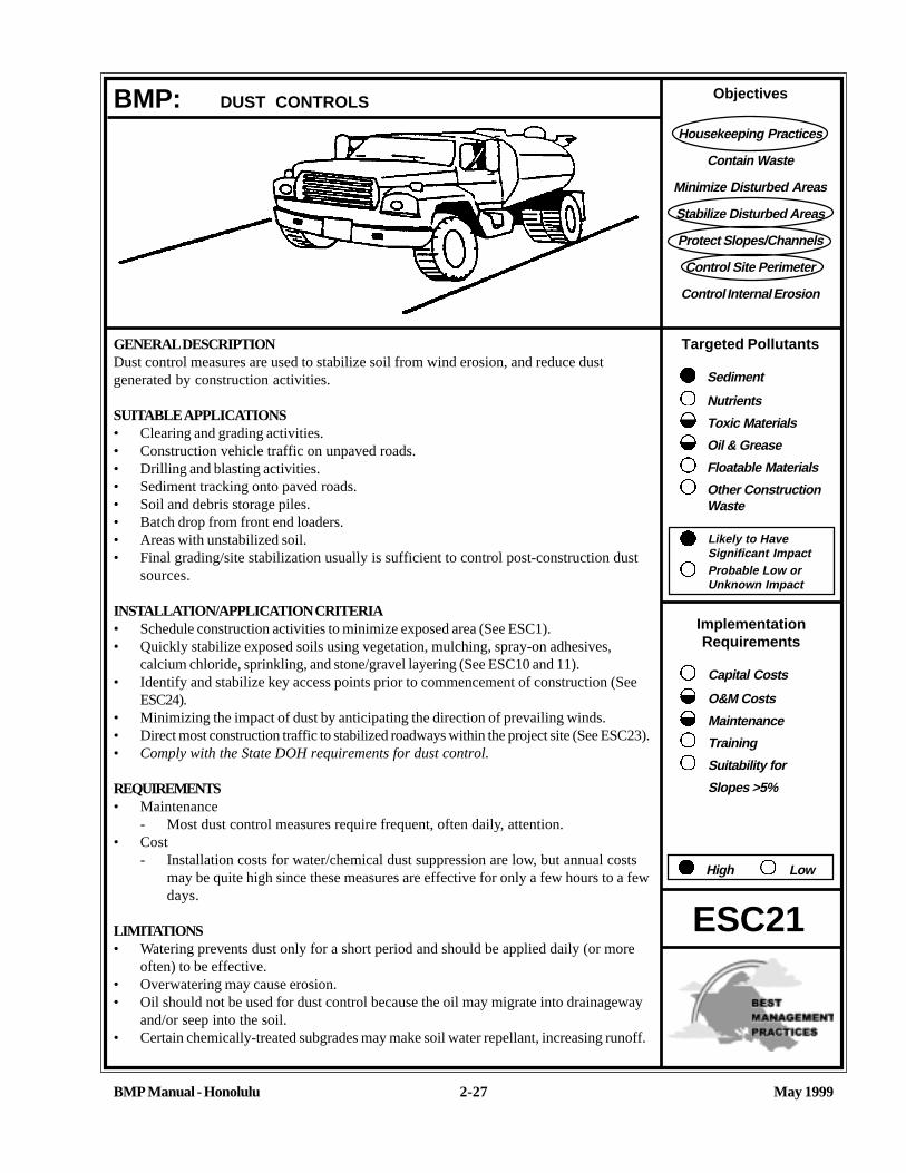
Objectives
Housekeeping Practices
Contain Waste
Minimize Disturbed Areas
Stabilize Disturbed Areas
Protect Slopes/Channels
Control Site Perimeter
Control Internal Erosion
Targeted Pollutants
Sediment
Nutrients
Toxic Materials
Oil & Grease
Floatable Materials
Other ConstructionWaste
Likely to HaveSignificant ImpactProbable Low orUnknown Impact
ImplementationRequirements
Capital Costs
O&M Costs
Maintenance
Training
Suitability for
Slopes >5%
High Low
May 1999BMP Manual - Honolulu 2-27
GENERAL DESCRIPTIONDust control measures are used to stabilize soil from wind erosion, and reduce dustgenerated by construction activities.
SUITABLE APPLICATIONS• Clearing and grading activities.• Construction vehicle traffic on unpaved roads.• Drilling and blasting activities.• Sediment tracking onto paved roads.• Soil and debris storage piles.• Batch drop from front end loaders.• Areas with unstabilized soil.• Final grading/site stabilization usually is sufficient to control post-construction dust
sources.
INSTALLATION/APPLICATION CRITERIA• Schedule construction activities to minimize exposed area (See ESC1).• Quickly stabilize exposed soils using vegetation, mulching, spray-on adhesives,
calcium chloride, sprinkling, and stone/gravel layering (See ESC10 and 11).• Identify and stabilize key access points prior to commencement of construction (See
ESC24).• Minimizing the impact of dust by anticipating the direction of prevailing winds.• Direct most construction traffic to stabilized roadways within the project site (See ESC23).• Comply with the State DOH requirements for dust control.
REQUIREMENTS• Maintenance
- Most dust control measures require frequent, often daily, attention.• Cost
- Installation costs for water/chemical dust suppression are low, but annual costsmay be quite high since these measures are effective for only a few hours to a fewdays.
LIMITATIONS• Watering prevents dust only for a short period and should be applied daily (or more
often) to be effective.• Overwatering may cause erosion.• Oil should not be used for dust control because the oil may migrate into drainageway
and/or seep into the soil.• Certain chemically-treated subgrades may make soil water repellant, increasing runoff.
BMP: DUST CONTROLS
ESC21

May 1999BMP Manual - Honolulu
ADDITIONAL INFORMATION: DUST CONTROLS
2-28
ESC21
Dust Control PracticesDust control BMP’s generally stabilize exposed surfaces and minimize activities that suspend or track dust particles.Table ESC21.1 shows which Dust Control BMPs apply to site conditions which cause dust. For heavily traveled anddisturbed areas, wet suppression (watering), chemical dust suppression, gravel or asphalt surfacing, temporary gravelconstruction entrances, equipment wash-out areas, and haul truck covers can be employed as dust control applications.Permanent or temporary vegetation and mulching and sand fences can be employed for areas of occasional or noconstruction traffic. Preventive measures would include minimizing surface areas to be disturbed, limiting on-site vehicletraffic to 15 miles per hour, and controlling the number and activity of vehicles on a site at any given time.
Many of the reasonably available control measures for controlling dust from construction sites can also be implementedas BMPs for storm water pollution prevention. Those BMPs include:• Pave, vegetate, or chemically stabilize access points where unpaved traffic surfaces adjoin paved roads.• Provide covers for haul trucks transporting materials that contribute to dust.• Provide for wet suppression or chemical stabilization of exposed soils.• Provide for rapid clean-up of sediments deposited on paved roads. Furnish stabilized construction road entrances
and vehicle wash down areas.• Stabilize unpaved haul roads, parking and staging areas. Reduce speed and trips on unpaved roads.• Implement dust control measures for material stockpiles.• Prevent drainage of sediment laden storm water onto paved surfaces.• Stabilize abandoned construction sites using vegetation or chemical stabilization methods.• Limit the amount of areas disturbed by clearing and earth moving operations by scheduling these activities in
phases.
For the chemical stabilization, there are many products available for chemically stabilizing gravel roadways and stock-piles. The types of chemicals available and recommendations for their use are tabulated in Table ESC21.2, CommonlyUsed Chemicals for Dust Control.

May 1999BMP Manual - Honolulu
ADDITIONAL INFORMATION: DUST CONTROLS
2-29
ESC21
In addition, there are many other BMPs identified in this handbook that provide dust control including:
• Seeding and Plantings (ESC10)• Mulching (ESC11)• Construction Road Stabilization (ESC23)• Stabilized Construction Entrances (ESC24)
Limitations• Oil treated subgrades should not be used because the oil may migrate into drainageways and/or seep into the soil.• Chemically treated subgrades may make the soil water repellant, interfering with long-term infiltration, and the
vegetation/re-vegetation of the site. Some chemical dust suppressants may be subject to freezing and may containsolvents and should be handled properly.
• Asphalt, as a mulch tack or chemical mulch, requires a 24 hour curing time to avoid adherence to equipment, workershoes, etc. Application should be limited because asphalt surfacing may eventually migrate into the drainagesystem.
• In compacted areas, watering and other liquid dust control measures may wash sediment or other constituents intothe drainage system.
REFERENCESBest Management Practices and Erosion Control Manual for Construction Sites, Flood Control District of MaricopaCounty, Arizona, September 1992.
California Air Pollution Control Laws, California Air Resources Board. 1992.
CalTrans, Standard Specifications, Sections 10, “Dust Control Section 17, “Watering”; and Section 18, “Dust Palliative”.
Prospects for Attaining the State Ambient Air Quality Standards for Suspended Particulate Matter (PM10), VisibilityReducing Particles, Sulfates, Lead, and Hydrogen Sulfide, California Air Resources Board, April 1991.
Sacramento County, Winterization Ordinance & Dust Control Ordinance (example).
USDA Soil Conservation Service, “Guides for Erosion and Sediment Control”.

TABLE ESC 21.1 DUST CONTROL BMPs FOR GIVEN SITE CONDITIONS
SITE
CONDITIONPermanentVegetation Mulching
WetSuppression(Watering)
ChemicalDust
Suppression
Gravel orAsphalt
SurfacingSand
Fences
Temporary GravelConstruction
Entrances/EquipmentWash Down
HaulTruckCovers
MinimizeExtentof AreaDisturbed
Disturbed Areas notSubject to Traffic
UU UU UU UU UU UU
Disturbed AreasSubject to Traffic
UU UU UU UU
Material Stock PileStabilization
UU UU UU UU
Demolition UU UU UU
Clearing/Excavation UU UU UU
Truck Traffic onUnpaved Roads
UU UU UU
Mud/Dirt Carry-Out UU UU
BMP Manual - Honolulu 2-30 May 1999

1 Motor oils and oil treatments are not recommended due to adverse effects on plant life and groundwater.
2 Not Recommended due to adverse effects on plant life.
TABLE ESC 21.2 COMMONLY USED CHEMICALS FOR DUST CONTROL
SALTS ORGANIC, NONPETROLEUM BASED
PETROLEUM BASEDPRODUCTS1
CHEMICAL TYPES CC Calcium Chloride2
CC Magnesium ChlorideCC Natural Brines
CC Calcium LignosulfonateCC Sodium LignosulfonateCC Ammonium Lignosulfonate
CC Bunker OilCC Asphalt PrimerCC Emusified Asphalt
LIMITATIONS Can lose effectiveness in dryperiods with low humidity. Leaches from road in heavyrain.
Not recommended for gravelroad surfaces with low fines.Recommended 10-20% fines.
Not affected by dry weather andlow humidity. Leached fromroad in heavy rain if notsufficiently cured
Best performance on gravelroads with high surface fines(10-30%) and dense compactsurface with loose gravel.
Generally effective regardless ofclimatic conditions; may potholein wet weather.
Best performance on gravelroads with 5-10% fines.
COMMENTS Calcium Chloride is popular. May become slippery when weton gravel surfaces with highfines.
Ineffective on gravel surfaceslow in fines. May becomeslippery when wet on gravelsurfaces with high fines content.
Creates a hardened crust.
BMP Manual - Honolulu 2-31 May 1999

Objectives
Housekeeping Practices
Contain Waste
Minimize Disturbed Areas
Stabilize Disturbed Areas
Protect Slopes/Channels
Control Site Perimeter
Control Internal Erosion
Targeted Pollutants
Sediment
Nutrients
Toxic Materials
Oil & Grease
Floatable Materials
Other ConstructionWaste
Likely to HaveSignificant ImpactProbable Low orUnknown Impact
ImplementationRequirements
Capital Costs
O&M Costs
Maintenance
Training
Suitability for
Slopes >5%
High Low
BMP Manual - Honolulu May 19992-32
GENERAL DESCRIPTIONA temporary access stream crossing is a temporary culvert, ford or bridge placed across awaterway to provide access for construction purposes for a period of less than one year.Temporary access crossings are not intended to be used to maintain traffic for the generalpublic.
SUITABLE APPLICATIONSTemporary stream crossings should be installed at all designated crossings of perennialand intermittent streams on the construction site, as well as for dry channels which may besignificantly eroded by construction traffic.
INSTALLATION/APPLICATION CRITERIARequires knowledge of stream flows and soil strength and should be designed under thedirection of a Hawaii registered engineer with knowledge of both hydraulics and construc-tion loading requirements for structures.
REQUIREMENTS• Maintenance
- Inspect weekly and after each significant rainfall, including assessment offoundations.
- Periodically remove silt from crossings.- Replace lost aggregate from inlets and outlets of culverts.
LIMITATIONS• May be an expensive for a temporary improvement.• Requires other BMPs to minimize soil disturbance during installation and removal.• Fords should only be used in dry weather.• Liability for damage resulting from the culvert is with the design engineer/contrac-
tor. It should be designed so it will not create flooding problems.
BMP: TEMPORARY STREAM CROSSING
ESC22

May 1999BMP Manual - Honolulu
ADDITIONAL INFORMATION: TEMPORARY STREAM CROSSING
2-33
ESC22
A temporary access stream crossing is a culvert, ford, or bridge placed across a waterway to provide access for con-struction for a period of less than one year. Temporary access crossings are not intended to be used for general publictraffic.
The purpose of this BMP is to provide a safe, erosion-free access across a stream for construction equipment. Minimumstandards and specifications for the design, construction, maintenance, and removal of the structure should be estab-lished by an engineer registered in Hawaii. Temporary stream crossings may be necessary to prevent constructionequipment from causing erosion of the stream and tracking sediment and other pollutants into the stream.
Temporary stream crossings are used as access points to construction sites when other detour routes may be too longor burdensome for the construction equipment. Often heavy construction equipment must cross streams or creeks, anddetour routes may impose too many constraints such as being too narrow or poor soil strength for the equipmentloadings. Additionally, the contractor may find a temporary stream crossing more economical for light-duty vehicles touse for frequent crossings, and may have less environmental impact than construction of a temporary access road.
Installation/ApplicationTemporary access stream crossings should be sized and installed according to the drainage design criteria of the localmunicipality. Design criteria should be based on standard engineering practices for culvert design with provisions forminimizing impacts on disturbed crossing areas. Three types of temporary access stream crossings may be considered:
Temporary Access Culvert: A temporary access culvert is effective in controlling erosion but will cause erosionduring installation and removal. A temporary culvert can be easily constructed and allows for heavy equipment loads.
Temporary Access Ford: A temporary access ford provides little sediment and erosion control and is ineffective incontrolling erosion in the stream channel. A temporary ford is the least expensive stream crossing and allows formaximum load limits. It also offers very low maintenance. Fords are more appropriate during the dry season and in aridareas.
Temporary Access Bridge: With the appropriate materials and designs, a temporary access bridge causes the leasterosion of the stream channel crossing during its installation and removal.
During the summer, rainfall is infrequent and many streams are dry. Under these conditions, a temporary access ford maybe sufficient. A ford is not appropriate if construction will continue through the winter rainy season, if summer thunder-storms are likely, or if the stream flows during most of the year. Temporary access culverts and bridges should then beconsidered and, if used, should be sized to pass a significant design storm (i.e., at least a 10-year storm). The temporarystream crossing should be protected against erosion, both to prevent excessive sedimentation in the stream and toprevent washout of the crossing (and, consequently, costly construction delays).
LimitationsSpecial care must be taken when crossing an environmentally sensitive waterway. Oils or other potentially hazardousmaterials shall not be used for surface treatments. Street runoff should not be allowed to spill down crossing sideslopes.Construction in watercourses should be at or near the natural elevation of the stream bed to prevent any potentialflooding upstream of the crossing. In addition, the following limitations may apply:

May 1999BMP Manual - Honolulu
ADDITIONAL INFORMATION: TEMPORARY STREAM CROSSING
2-34
ESC22
• May be expensive temporary cost• Increased soil disturbance upon installation and removal• Temporary culverts need regular maintenance and can cause erosion if the culvert becomes clogged.• A temporary ford offers little if any erosion control in flowing streams and can often make erosion worse. Fords
should only be used in the dry season on dry streams.
Construction in waterways is subject to additional permit requirements. Contact the US Army Corps of Engineers andState Department of Land and Natural Resources for additional information.
REFERENCESBank and Shore Protection, CalTrans - November 1970.
Best Management Practices and Erosion Control Manual for Construction Sites, Flood Control District of MaricopaCounty, Arizona, September, 1992.

May 1999BMP Manual - Honolulu
ADDITIONAL INFORMATION: TEMPORARY STREAM CROSSING
2-35
ESC22
AGGREGATE FILL
FILTER CLOTH
AGGREGATE FILL 12” MIN.
FILTERCLOTH
HIGH FLOW AREA
FILTER CLOTHAGGREGATEFILL
HIGH FLOW AREA
FILTER CLOTHAGGREGATEFILL
FLAT BANKS STEEP BANKS
MULTIPLE PIPESMULTIPLE PIPES
AGGREGATE FILLAGGREGATE FILL
HIGH FLOW AREA HIGH FLOW AREA
FILTER CLOTH FILTER CLOTH
AGGREGATE FILL PERM.A.G. SPECIFICATIONS
FILTER CLOTH
TEMPORARY ACCESS CULVERT

May 1999BMP Manual - Honolulu
ADDITIONAL INFORMATION: TEMPORARY STREAM CROSSING
2-36
ESC22
STRE
AM BE
D
SURFACE FLOWDIVERTED BY SWALE
AGGREGATE BED OVERFILTER CLOTH
AGGREGATE APPROACH5:1 MAXIMUM, SLOPE ON ROAD
SURFACE FLOW DIVERTEDBY SWALE
WATER LEVEL SURFACE FLOW DIVERTEDBY SWALE
NEW ROAD
ORIGINAL STREAM BED
FILTER CLOTH
AGGREGATE
TEMPORARY ACCESS FORD

Objectives
Housekeeping Practices
Contain Waste
Minimize Disturbed Areas
Stabilize Disturbed Areas
Protect Slopes/Channels
Control Site Perimeter
Control Internal Erosion
Targeted Pollutants
Sediment
Nutrients
Toxic Materials
Oil & Grease
Floatable Materials
Other ConstructionWaste
Likely to HaveSignificant ImpactProbable Low orUnknown Impact
ImplementationRequirements
Capital Costs
O&M Costs
Maintenance
Training
Suitability for
Slopes >5%
High Low
May 1999BMP Manual - Honolulu 2-37
GENERAL DESCRIPTIONAccess roads, subdivision roads, parking areas, and other on-site vehicle transportationroutes should be stabilized immediately after grading and frequently maintained to preventerosion and control dust.
SUITABLE APPLICATIONS• Temporary construction traffic.• Phased construction projects and off-site road access.• Detour roads.• Construction during wet weather.
INSTALLATION/APPLICATION CRITERIA• Road should follow topographic contours to reduce erosion of the roadway.• The roadway slope should not exceed 15 percent.• Gravel roads should be a minimum 4-inch thick, 2-3 inch coarse aggregate base applied
immediately after grading, or as recommended by soils engineer.• Chemical stabilizers or water are usually required on gravel or dirt roads to prevent
dust (see Dust Control ESC21).
REQUIREMENTS• Maintenance
- Periodically apply additional aggregate on gravel roads.- Active dirt construction roads are commonly watered three or more times per day
during the dry season.- Inspect weekly, and after each rain.- Repair any eroded areas immediately.
• Cost- Gravel construction roads are moderately expensive, but cost is often balanced by
reductions in construction delay.- No additional costs for dust control on construction roads should be required
above that needed to meet local air quality requirements.
LIMITATIONS• The roadway must be removed or paved when construction is complete.• Certain chemical stabilization methods may cause storm water or soil pollution and
should not be used (see Dust Control ESC21).• Management of construction traffic is subject to air quality control measures. Contact
the local air quality management agency.
BMP: CONSTRUCTION ROAD STABILIZATION
ESC23

May 1999BMP Manual - Honolulu
ADDITIONAL INFORMATION: CONSTRUCTION ROAD STABILIZATION
2-38
ESC23
Areas which are graded for construction vehicle transport and parking purposes are especially susceptible to erosionand dust. The exposed soil surface is continually disturbed, leaving no opportunity for vegetative stabilization. Suchareas also tend to collect and transport runoff waters along their surfaces. During wet weather, they often becomemuddy quagmires which generate significant quantities of sediment that may pollute nearby streams or be transportedoff-site on the wheels of construction vehicles. Dirt roads can become so unstable during wet weather that they arevirtually unusable.
Efficient construction road stabilization not only reduces on-site erosion but can significantly speed on-site work, avoidinstances of immobilized machinery and delivery vehicles, and generally improve site efficiency and working conditionsduring adverse weather.
Installation/Application CriteriaWhere feasible, alternative routes should be made for construction traffic; one for use in dry condition, the other for wetconditions which incorporate the measures listed for this BMP. Permanent roads and parking areas should be paved assoon as possible after grading. As an alternative where construction will be phased, the early application of gravel orchemical stabilization may solve potential erosion and stability problems. Temporary gravel roadway should be consid-ered during the rainy season and/or on slopes greater than 5 percent.
When gravel road is needed, apply a minimum 4-inch course of 2 to 4-inch crushed rock. gravel base, or crushedsurfacing base course immediately after grading or the completion of utility installation within the right-of-way. Chemicalstabilization may also be used upon compacted native sub-grade (see the Dust Control BMP ESC21). These chemicalcontrols should be applied per the manufacturer’s directions.
Temporary roads should follow the contour of the natural terrain to the maximum extent possible. Slope should notexceed 15 percent. Roadways should be carefully graded to drain transversely. Provide drainage swales on each side ofthe roadway in the case of a crowned section, or one side in the case of super-elevated section. Simple gravel bermswithout a trench can also be used.
Installed inlets should be protected to prevent sediment-laden water from entering the storm sewer system (see “StormDrain Inlet Protection” ESC54).
REFERENCESBest Management Practices and Erosion Control Manual for Construction Sites, Flood Control District of MaricopaCounty, Arizona, September 1992.
Manual of Standards of Erosion and Sediment Control Measures, Association of Bay Area Governments, June 1981.
Stormwater Management Water for the Puget Sound Basin, Washington State Department of Ecology, The TechnicalManual February 1992, Publication # 91-75.
Virginia Erosion and Sedimentation Control Handbook, Virginia Department of Conservation and Recreation, Division ofSoil and Water Conservation, 1991.
Water Quality Management Plan for the Lake Tahoe Region, Volume II, Handbook of Management Practices, TahoeRegional Planning Agency - November 1988.

Objectives
Housekeeping Practices
Contain Waste
Minimize Disturbed Areas
Stabilize Disturbed Areas
Protect Slopes/Channels
Control Site Perimeter
Control Internal Erosion
Targeted Pollutants
Sediment
Nutrients
Toxic Materials
Oil & Grease
Floatable Materials
Other ConstructionWaste
Likely to HaveSignificant ImpactProbable Low orUnknown Impact
ImplementationRequirements
Capital Costs
O&M Costs
Maintenance
Training
Suitability for
Slopes >5%
High Low
May 1999BMP Manual - Honolulu 2-39
GENERAL DESCRIPTIONThe construction entrance practice is a stabilized pad of aggregate underlain with filtercloth located at any point where traffic will be entering or leaving a construction site to orfrom a public right-of-way, street, alley, sidewalk or parking area. Stabilizing the construc-tion entrance significantly reduces the amount of sediment (dust, mud) tracked off-site,especially if a washrack is incorporated for removing caked on sediment.
SUITABLE APPLICATIONS• All points of construction ingress and egress.• Unpaved areas where sediment tracking occurs from site onto paved roads.
INSTALLATION/APPLICATION CRITERIA• Construct on level ground where possible.• Stones should be 1-3 inches.• Minimum depth of stones should be 6 inches or as recommended by soils engineer.• Length should be 50-foot minimum, and 30-foot minimum width.• Provide ample turning radii as part of entrance.
REQUIREMENTS• Maintenance
- Inspect monthly and after each rainfall.- Replace gravel material when surface voids are visible.- Remove all sediment deposited on paved roadways within 24 hours.- Remove gravel and filter fabric at completion of construction
• Cost: Average annual cost for installation and maintenance (Source: EPA, 1992)- Without Wash Rock: $1500 each.- With Wash Rock: $2200 each.
LIMITATIONS• Requires periodic top dressing with additional stones.• Should be used in conjunction with street sweeping on adjacent public right-of-way.
BMP: STABILIZED CONTRUCTION ENTRANCE
ESC24

May 1999BMP Manual - Honolulu
ADDITIONAL INFORMATION: STABILIZED CONSTRUCTION ENTRANCE
2-40
ESC24
A stabilized construction entrance is a pad of aggregate underlaid with filter cloth located at any point where traffic willbe entering or leaving a construction site to or from a public right-of-way, street, alley, sidewalk or parking area. Thepurpose of a stabilized construction entrance is to reduce or eliminate the tracking of sediment onto public rights-of-wayor streets. Reducing trackout of sediments and other pollutants onto paved roads helps prevent deposition of sedimentsinto local storm drains and production of airborne dust.
Where traffic will be entering or leaving, a stabilized construction entrance should be used at all points of constructioningress and egress. NPDES permits require that appropriate measures be implemented to prevent trackout of sedimentsonto paved roadways, which is a significant source of sediments derived from mud and dirt carryout from the unpavedroads and construction sites.
Stabilized construction entrances are moderately effective in removing sediment from equipment leaving a constructionsite. The entrance should be build on the level ground. Advantages of the Stabilized Construction Entrance is that itdoes remove some sediment from equipment and serves to channel construction traffic in and out of the site at specifiedlocations. Efficiency is greatly increased when a washing rack is included as part of a stabilized construction entrance.
See the City and County of Honolulu’s “Rules Relating to Soil Erosion Standards and Guidelines,” for additionalinformation.
The entrance must be properly graded to prevent runoff from leaving the construction site. When wash areas areprovided, washing is done on a reinforced concrete pad (if significant washing is necessary) or in an area stabilized withcrushed stone which drains into a properly constructed sediment trap or basin (ESC55 and 56). Sediment barriers areprovided to prevent sediments from entering into the stormwater sewer system, ditch, or waterway.
Limitations• Construct on level ground.• Stabilized construction entrances are rather expensive to construct and when a wash rack is included, a sediment
trap of some kind must also be provided to collect wash water runoff.• Requires periodic top dressing with additional stones.• Should be used in conjunction with street sweeping on adjacent public right-of-way.
REFERENCESBest Management Practices and Erosion Control Manual for Construction Sites, Flood Control District of MaricopaCounty, Arizona, September 1992.
Manual of Standards of Erosion and Sediment Control Measures, Association of Bay Area Governments, June 1981.
Proposed Guidance Specifying Management Measures for Sources of Nonpoint Pollution in Coastal Waters, WorkGroup Working Paper, USEPA, April, 1992.
Stormwater Management Water for the Puget Sound Basin, Washington State Department of Ecology, The TechnicalManual February 1992, Publication # 91-75.
Virginia Erosion and Sedimentation Control Handbook, Virginia Department of Conservation and Recreation, Division ofSoil and Water Conservation, 1991.
Water Quality Management Plan for the Lake Tahoe Region, Volume II, Handbook of ManagementPractices, Tahoe Regional Planning Agency - November 1988.

May 1999BMP Manual - Honolulu
ADDITIONAL INFORMATION: STABILIZED CONSTRUCTION ENTRANCE
2-41
ESC24
STABILIZED CONSTRUCTION ENTRANCE
DITCH TO CARRYWASH WATER TOSEDIMENT BASIN ORTRAP
WASH RACK
VEHICLE LENGTH
CHANNEL/DITCH BOTTOM
REINFORCED CONRETE
DRAIN SPACEMETAL BAR
WASH RACK (SCHEMATIC)
FILTER FABRIC
HARD SURFA
CE
PUBLIC R
OAD
1” TO 3” COARSEAGGREGATE
50’ MIN.
30’
MIN
.
6” M
IN.
R20’

Objectives
Housekeeping Practices
Contain Waste
Minimize Disturbed Areas
Stabilize Disturbed Areas
Protect Slopes/Channels
Control Site Perimeter
Control Internal Erosion
Targeted Pollutants
Sediment
Nutrients
Toxic Materials
Oil & Grease
Floatable Materials
Other ConstructionWaste
Likely to HaveSignificant ImpactProbable Low orUnknown Impact
ImplementationRequirements
Capital Costs
O&M Costs
Maintenance
Training
Suitability for
Slopes >5%
High Low
BMP Manual - Honolulu May 1999
BMP: PROTECTION OF STOCKPILES
ESC25
GENERAL DESCRIPTIONStockpiles can be a significant source of erosion and sediment, and measures should betake to mitigate the potential for nonpoint source pollution. Information to be providedto the City and County of Honolulu, Department of Planning and Permitting, whenapplying for a stockpiling permit include “a plot plan showing the property lines,easements and setbacks, topography, and the location of the proposed stockpile, quanti-ties, height of stockpile, life of stockpile and source of the material to be stockpiled,” andother information as may be required to “control the emission of air-borne dust, drainagerunoff or erosion problems.”
SUITABLE APPLICATIONS• Stockpiles for gravel, topsoil in roadway areas.
• Stockpiles for excavated material to be moved to off-site locations.
• Stockpiles of imported material.
• Stockpiles for surcharging to stabilize or consolidate an area.
INSTALLATION/APPLICATION CRITERIAL• Provide adequate setback from waterways.
• Provide earth dikes or other diversion to keep runoff away from stockpiles.
• Provide silt fences at the toe of the stockpile to mitigate runoff during rain events.
• Cover, grass or provide other stabilization measures.
• Provide adequate setback distance from lot lines.
• Provide silt basins where required.
REQUIREMENTS• Maintenance
- Inspect periodically and after every significant rainfall; repair as necessary.
LIMITATIONSStockpiles are for temporary storage of material only. Provisions should be made forpermanent movement of stockpiled material. Failure to contain stockpiled material maycause downstream erosion or flood damage. Stockpiles not properly stabilized maycause fugitive dust problems.
2-42
Graphic by City & County of Honolulu, 1999

May 1999BMP Manual - Honolulu
BMP: PROTECTION OF STOCKPILES (Continue)
ESC25
REFERENCES“Rules Relating to Erosion Control Standards and Guidelines,” April 1999, Department of Planning and Permitting,City and County of Honolulu.
Chapter 14, Article 14. Permits, Bonds and Inspection for Grading, Soil Erosion and Sediment Control, RevisedOrdinances of Honolulu, 1990 as amended.
California Storm Water Best Management Best Management Practice Handbooks, Construction Activity Best Manage-ment Practice Handbook, March 1993, Camp Dresser & McKee et. al. For the California Storm Water Quality TaskForce.
2-43

Objectives
Housekeeping Practices
Contain Waste
Minimize Disturbed Areas
Stabilize Disturbed Areas
Protect Slopes/Channels
Control Site Perimeter
Control Internal Erosion
Targeted Pollutants
Sediment
Nutrients
Toxic Materials
Oil & Grease
Floatable Materials
Other ConstructionWaste
Likely to HaveSignificant ImpactProbable Low orUnknown Impact
ImplementationRequirements
Capital Costs
O&M Costs
Maintenance
Training
Suitability for
Slopes >5%
High Low
BMP Manual - Honolulu May 19992-44
GENERAL DESCRIPTIONThe temporary earth dike is a temporary berm or ridge of compacted soil, used to divertrunoff or channel water to a desired location.
SUITABLE APPLICATIONSEarth dikes are typically used to divert concentrated runoff through disturbed areas intoanother BMP (e.g., sediment basins), to divert runoff away from disturbed or unstable slopes,to divert runoff from off-site and undisturbed areas around disturbed areas, and as a contain-ment for construction materials and wastes. The dikes should remain in place until the dis-turbed areas are permanently stabilized. The dikes must be on-site and must safely conveyanticipated flood flows.
INSTALLATION/APPLICATION CRITERIA
• All dikes should be compacted by earth-moving equipment.• All dikes should have positive drainage to a stabilized outlet.• Top width may be wider and side slopes may be flatter at crossings for construction
traffic.• Dikes should direct sediment-laden runoff into a sediment trapping device.• Dikes should be stabilized with vegetation, chemicals, or physical devices.
REQUIREMENTS• Maintenance
- Inspect periodically and after every significant rainfall; repair as necessary.• Cost
- Cost ranges from $15 to $55 per foot for both earthwork and stabilization anddepends on availability of material, site location, and access.
LIMITATIONSDikes should not be used for drainage areas greater than 10 acres, or along slopes greaterthan 10 percent. For larger areas more permanent drainage structures should be built. Alldrainage structures should be built in compliance with local municipal requirements.
• Earth dikes may create more disturbed area on site and become barriers to constructionequipment.
• Earth dikes must be stabilized immediately, which adds cost and maintenance concerns.• Diverted storm water may cause downstream flood damage.• Dikes should not be constructed of soils which may be easily eroded.• Regrading the site to remove the dike may add additional cost.
BMP: EARTH DIKE
ESC30

May 1999BMP Manual - Honolulu
ADDITIONAL INFORMATION: EARTH DIKE
2-45
ESC30
The temporary earth dike is a berm or ridge of compacted soil, located in such a manner as to divert storm water to asediment trapping device or stabilized outlet, thereby reducing the potential for erosion and offsite sedimentation. Earthdikes can also be used to divert runoff from off-site and from undisturbed areas away from disturbed areas, and to divertsheet flows away from unprotected slopes.
An earth dike does not itself control erosion or remove sediment from runoff; a dike prevents erosion by directing runoff toan erosion control device such as a sediment trap or directing runoff away from an erodible area. Temporary diversion dikesshould not adversely impact adjacent properties and must conform to local floodplain management regulations, and shouldnot be used in areas with slopes steeper than 10%.
• The advantages of the temporary earth dike include the ability to handle flows from large drainage areas.• Once stabilized, earth dikes require relatively little maintenance. Additionally, the earth dikes are relatively inexpensive
to install since the soil material required for construction may be available on-site, and can be constructed as part of theinitial grading operations, while the equipment is on-site.
• Uses on-site materials.
Installation/Application CriteriaTemporary earth dikes are a practical, inexpensive BMP used to divert storm water runoff. Temporary diversion dikes shouldbe installed in the following manner:
1. All dikes should be compacted by earth-moving equipment.2. All dikes should have positive drainage to an outlet.3. All dikes should have 2:1 side slopes, 18 inches minimum height, and a minimum top width of 24 inches. Top width may
be wider and side slopes may be flatter at crossings for construction traffic.4. The outlet from the earth dike must function with a minimum of erosion. Runoff should be conveyed to a sediment
trapping device such as a sediment trap (ESC55) or sediment basin (ESC56) when either the dike channel or thedrainage area above the dike are not adequately stabilized.
5. Temporary stabilization may be achieved using seed and mulching for slopes less than 5%, and either rip-rap or sod forslopes in excess of 5%. In either case, stabilization of the earth dike should be completed immediately after constructionor prior to the first rain.
6. If riprap is used to stabilize the channel formed along the toe of the dike, the following typical specifications apply:
CHANNEL RIPRAPGRADE STABILIZATION0.5-1.0% 4" Rock1.1-2.0% 6" Rock2.1- 4.0% 8" Rock4.1-5.0% 8-12" Riprap
7. The stone riprap, recycled concrete, etc. used for stabilization should be pressed into the soil with constructionequipment.
8. Filter cloth may be used to cover dikes in use for long periods.9. Construction activity on the earth dike should be kept to a minimum.
REFERENCESBest Management Practices and Erosion Control Manual for Construction Sites, Flood Control District of Maricopa County,Arizona, September 1992.
“Draft - Sedimentation and Erosion Control, An Inventory of Current Practices, U.S.E.P.A., April, 1990.

May 1999BMP Manual - Honolulu
ADDITIONAL INFORMATION: EARTH DIKE
2-46
ESC30
Erosion and Sediment Control Handbook, S.J. Goldman, K. Jackson, T.A. Bursetynsky, P.E., McGraw Hill Book Company.
Manual of Standards of Erosion and Sediment Control Measures, Association of Bay Area Governments, June 1981.
Water Quality Management Plan for the Lake Tahoe Region, Volume II, Handbook of Management Practices, TahoeRegional Planning Agency - November 1988.

May 1999BMP Manual - Honolulu
ADDITIONAL INFORMATION: EARTH DIKE
2-47
ESC30
STABILIZATION AS REQUIRED ON STEEPSLOPES EXCAVATE TO PROVIDE REQUIREDFLOW WIDTH AT FLOW DEPTH
2:1 SLOPEOR FLATTER,BOTH SIDES
GRADE LINE
RUNOFF
B
A
C
D
REQUIREMENTS BASED ON UPSTREAM DRAINAGE AREA
DIKE 1(5 ACRES OR LESS)
DIKE 1(5-10 ACRES)
A-DIKE HEIGHTB-DIKE WIDTH
C-FLOW WIDTH
D-FLOW DEPTH
18”
15”
6’
36”36”
8”
4’
24”
TEMPORARY DIVERSION DIKE

Objectives
Housekeeping Practices
Contain Waste
Minimize Disturbed Areas
Stabilize Disturbed Areas
Protect Slopes/Channels
Control Site Perimeter
Control Internal Erosion
Targeted Pollutants
Sediment
Nutrients
Toxic Materials
Oil & Grease
Floatable Materials
Other ConstructionWaste
Likely to HaveSignificant ImpactProbable Low orUnknown Impact
ImplementationRequirements
Capital Costs
O&M Costs
Maintenance
Training
Suitability for
Slopes >5%
High Low
BMP Manual - Honolulu May 19992-48
GENERAL DESCRIPTIONTemporary drains and swales are used to divert off-site runoff around the constructionsite, divert runoff from stabilized areas around disturbed areas, and direct runoff intosediment basins or traps.
SUITABLE APPLICATIONSTemporary drains and swales are appropriate for diverting any upslope runoff aroundunstabilized or disturbed areas of the construction site:• Prevent slope failures.• Prevent damage to adjacent property.• Prevents erosion and transport of sediments into water ways.• Increases the potential for infiltration.• Diverts sediment-laden runoff into sediment basins or traps.
INSTALLATION/APPLICATION CRITERIATemporary drainage swales will effectively convey runoff and avoid erosion if builtproperly: Size temporary drainage swales using local drainage design criteria. A permanentdrainage channel must be designed by a professional engineer (see the local drainagedesign criteria for proper design).• At a minimum, the drain/swale should conform to predevelopment drainage patterns
and capacities.• Construct the drain/swale with an uninterrupted, positive grade to a stabilized outlet.• Provide erosion protection or energy dissipation measures if the flow out of the drain
or swale can reach an erosive velocity.
REQUIREMENTS• Maintenance
- Inspect weekly and after each rain.- Repair any erosion immediately.- Remove sediment which builds up in the swale and restricts its flow capacity.
• Cost- The cost of a drainage swale increases with drainage area and slope. Typically,
swales for controlling internal erosion are inexpensive.
LIMITATIONS• Temporary drains and swales or any other diversion of runoff should not ad-
versely impact upstream or downstream properties.• Temporary drains and swales must conform to local flood plain management
requirements.
BMP: TEMPORARY DRAINS AND SWALES
ESC31

May 1999BMP Manual - Honolulu
ADDITIONAL INFORMATION: TEMPORARY DRAINS AND SWALES
2-49
ESC31
Slopes that are formed during cut and fill operations should be protected from erosion by runoff. A combination of atemporary drainage swale and an earth dike (see ESC30) at the top of a slope can safely divert runoff to a location whereit can safely be brought to the bottom of the slope (see Pipe Slope Drain ESC32). A combination dike and swale is easilyconstructed by a single pass of a bulldozer or grader and compacted by a second pass of the tracks or wheels over theridge. Diversion structures should be installed when the site is initially graded, and remain in place until post-construc-tion BMPs are installed and/or the slopes are stabilized.
Diversion practices concentrate the volume of surface runoff, increasing its velocity and erosive force. Thus, the flow outof the drain or swale must be directed onto a stabilized area or into a grade stabilization structure. A swale should bestabilized using vegetation, chemical treatment, rock rip-rap, matting, or other physical means of stabilization, if significanterosion will occur. Any drain or swale which conveys sediment-laden runoff must be diverted into a sediment basin or trapbefore it is discharged from the site.
Installation/Application CriteriaDiversion drains or swales are only effective if they are properly installed. Swales are more effective than dikes because theytend to be more stable. The combination of a swale with a dike on the downhill side is the most cost-effective diversion.
Standard engineering design criteria for small open channel and closed conveyance systems should be used (see the Cityand County of Honolulu’s “Storm Drainage Standards.”) Unless the City and County of Honolulu drainage design criteriastate otherwise, drains or swales should be designed as follows:
• No more than 5 acres may drain to a temporary drain or swale• Place the drain or swale above, not on, a cut and fill slope• Swale bottom width should be at least 2 ft• Depth of the swale should be at least 18 inches• Side slopes should be 2:1 or flatter• Drain or swale should be layed at a grade of at least 1 percent, but not more than 15 percent• The swale must not be overtopped by the 10-year, 24-hour storm, irrespective of the design criteria stated above• Remove all trees, stumps, obstructions, and other objectionable material from the swale when it is built• Compact any fill material along the path of the swale• Stabilize all swales immediately. Seed and mulch swales at a slope of less than 5 percent, and use rip-rap or sod for
swales with a slope between 5 and 15 percent• Do not operate construction vehicles across a swale unless a stabilized crossing is provided.• The cost of swales and other diversion devices is generally included in the earthwork cost, as a separate item under
the grading budget of the project construction contract.
REFERENCESBest Management Practices and Erosion Control Manual for Construction Sites, Flood Control District of MaricopaCounty, Arizona, September 1992.
“Draft - Sedimentation and Erosion Control, An Inventory of Current Practices”, U.S.E.P.A., April, 1990.
Manual of Standards of Erosion and Sediment Control Measures, Association of Bay Area Governments, June 1981.
Stormwater Management Water for the Puget Sound Basin, Washington State Department of Ecology, The TechnicalManual - February 1992, Publication # 91-75.
Water Quality Management Plan for the Lake Tahoe Region, Volume II , Handbook of ManagementPractices, Tahoe Regional Planning Agency - November 1988.
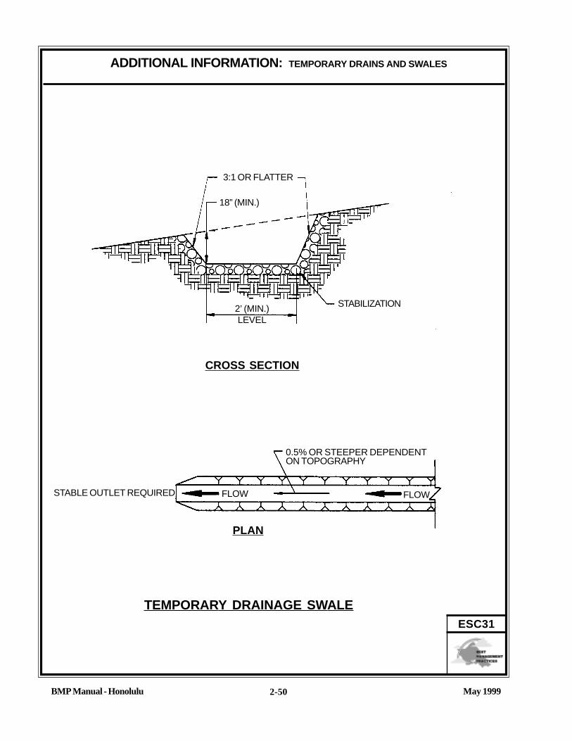
May 1999BMP Manual - Honolulu
ADDITIONAL INFORMATION: TEMPORARY DRAINS AND SWALES
2-50
ESC31
TEMPORARY DRAINAGE SWALE
0.5% OR STEEPER DEPENDENTON TOPOGRAPHY
STABILIZATION2’ (MIN.)LEVEL
18” (MIN.)
3:1 OR FLATTER
CROSS SECTION
STABLE OUTLET REQUIRED
PLAN
FLOWFLOW
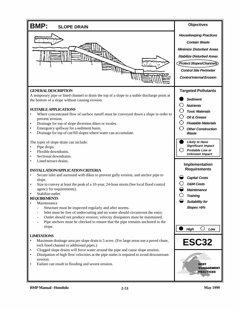
Objectives
Housekeeping Practices
Contain Waste
Minimize Disturbed Areas
Stabilize Disturbed Areas
Protect Slopes/Channels
Control Site Perimeter
Control Internal Erosion
Targeted Pollutants
Sediment
Nutrients
Toxic Materials
Oil & Grease
Floatable Materials
Other ConstructionWaste
Likely to HaveSignificant ImpactProbable Low orUnknown Impact
ImplementationRequirements
Capital Costs
O&M Costs
Maintenance
Training
Suitability for
Slopes >5%
High Low
May 1999BMP Manual - Honolulu 2-51
GENERAL DESCRIPTIONA temporary pipe or lined channel to drain the top of a slope to a stable discharge point atthe bottom of a slope without causing erosion.
SUITABLE APPLICATIONS• Where concentrated flow of surface runoff must be conveyed down a slope in order to
prevent erosion.• Drainage for top of slope diversion dikes or swales.• Emergency spillway for a sediment basin.• Drainage for top of cut/fill slopes where water can accumulate.
The types of slope drain can include:• Pipe drops.• Flexible downdrains.• Sectional downdrains.• Lined terrace drains.
INSTALLATION/APPLICATION CRITERIA• Secure inlet and surround with dikes to prevent gully erosion, and anchor pipe to
slope.• Size to convey at least the peak of a 10-year, 24-hour storm (See local flood control
agency for requirements).• Stabilize outlet.REQUIREMENTS• Maintenance
- Structure must be inspected regularly and after storms.- Inlet must be free of undercutting and no water should circumvent the entry.- Outlet should not produce erosion; velocity dissipators must be maintained.- Pipe anchors must be checked to ensure that the pipe remains anchored to the
slope.
LIMITATIONS• Maximum drainage area per slope drain is 5 acres. (For large areas use a paved chute,
rock lined channel or additional pipes.)• Clogged slope drains will force water around the pipe and cause slope erosion.• Dissipation of high flow velocities at the pipe outlet is required to avoid downstream
erosion.• Failure can result in flooding and severe erosion.
BMP: SLOPE DRAIN
ESC32

May 1999BMP Manual - Honolulu
ADDITIONAL INFORMATION: SLOPE DRAIN
2-52
ESC32
The slope drain may be a rigid pipe, such as corrugated metal, a flexible conduit, or a lined terrace drain with the inletplaced on the top of a slope. The drain conveys concentrated runoff down to the bottom of the slope. The BMPtypically is used in combination with a diversion control, such as a temporary dike or swale, at the top of the slope, andserves as a temporary BMP to reduce or eliminate slope erosion until permanent BMPs are installed and the slope isstabilized.
The slope drain is applicable for any construction site where concentrated surface runoff can accumulate and must beconveyed down the slope in order to prevent erosion. The slope drain is effective because it prevents the stormwaterfrom flowing directly down the slope by confining all the runoff into an enclosed pipe or channel. Due to the time lagbetween grading slopes and installation of permanent storm water collection systems and slope stabilization measures,temporary provisions to intercept runoff are sometimes necessary. Particularly in steep terrain, slope drains can protectunstabilized areas from erosion. Typical uses include:
• Emergency spillway for a sediment basin.• Drainage for top of cut/fill slopes where storm water can accumulate and must be conveyed down the slope.
Installation/Application CriteriaTemporary slope drains are highly effective in eliminating slope erosion. Installation and maintenance requirements aresmall, especially when flexible pipe is used. General criteria:
• Gully erosion is the major problem with slope drains. Inlet structures must be securely entrenched and compacted toavoid severe gully erosion.
• The drain must be securely anchored to the slope and must be adequately sized to carry the capacity of the designstorm and associated forces.
• The outlet must be stabilized with rip-rap, concrete or other type of energy dissipator, or directed into a stablesediment trap or basin.
• A debris rack is recommended at the inlet. and should be encouraged for larger pipes and at the outlet as a safetydevice to prevent small children from entering the pipe.
Materials:Material selection and criteria for the pipe slope drain should conform to the City and County of Honolulu criteria. Soiltype, rainfall patterns, construction schedule, and available supply are some of the factors to be considered. Thefollowing types of slope drains are commonly used:
• Rigid Pipe: This type of slope drain is also known as a pipe drop. The pipe usually consists of corrugated metal pipe orrigid plastic pipe. The pipe is placed on undisturbed or compacted soil and secured into the slope. One foot minimumcover is required on the pipe, and concrete thrust blocks must be used when required by the municipality or warrantedby the calculated thrust forces. Collars should be properly installed and secured with metal strappings or watertightcollars.
• Flexible Pipe: The flexible pipe slope drain consists of a flexible conduit of heavy duty material. The conduit material issecurely anchored into the slope and connections are watertight. The conduit should be securely fastened to the metalinlet and outlet conduit sections with metal strappings or water tight collars.
• Sectional Downdrains: The sectional downdrain consists of pre-fabricated sectional conduit of half-round or third-round material. The sectional downdrain performs similar to a flume or chute. The pipe must be placed on undisturbedor compacted soil and secured into the slope.
• Concrete-lined Terrace Drain: This is a concrete channel for draining water from a terrace on a slope to the next level.These drains are after permanent structures which should be designed according to the City andCounty of Honolulu’s drainage design criteria.

May 1999BMP Manual - Honolulu
ADDITIONAL INFORMATION: SLOPE DRAIN
2-53
ESC32
Design:Unless specified by the local municipality, the capacity for temporary drains should be sufficient to handle the peakrunoff from a 10-year, 24-hour rainfall event. The pipe size may be computed using the Rational Method or a methodestablished by the City and County of Honolulu. Higher flows must be safely stored or routed to prevent any offsiteconcentration of flow, and any erosion of the slope.
As a guide, temporary pipe slope drains should not be sized smaller than shown in the following table:
MINIMUM MAXIMUMPIPE DIAMETER DRAINAGE AREA (ACRES)12" 0.518" 1.521" 2.524" 3.530" 5.0
Permanent improvements must be designed and installed if the drainage area is greater than 5 acres.
The following additional design criteria should be considered:• Construct the pipe slope drain entrance of a standard flared end section with a minimum 6-inch metal toe plate to
prevent runoff from undercutting the pipe inlet. The slope of the entrance is usually at least 3 percent.• Thoroughly compact the soil around and under the pipe and entrance section.• Securely fasten the slope drain sections together, have gasketed watertight fittings, and securely anchored into the
soil.• Secure the flared inlet section to the slope drain and have watertight connecting bands.• Use interceptor dikes to direct runoff into a slope drain. The height of the dike should be at least 1 foot higher at all
points than the top of the inlet pipe.• If the pipe slope drain is conveying sediment-laden water, direct all flows into a sediment trap (ESC55) or sediment
basin (ESC56).• Unless the pipe directly enters a sediment trap/basin, stabilize the area below the outlet with a riprap apron.
LimitationsInstallation is critical for effective use of the pipe slope drain to minimize potential gully erosion. Maximum drainage areaper pipe slope drain is 5 acres. For larger areas use a paved chute, rock lined channel or additional pipes. (See the localmunicipality for drainage requirements)
• During large storms, pipe slope drains may become clogged or overcharged, forcing water around the pipe andcausing extreme slope erosion.
• Structures for dissipation of high flow velocities at the pipe outlet must be constructed to avoid downstreamerosion.
• Failure of this type of temporary structure may result in flooding and severe erosion.• If the sectional downdrain is not sized correctly, the runoff can spill over the drain sides causing gully erosion, and
potential failure of the structure.
May 1999BMP Manual - Honolulu
ADDITIONAL INFORMATION: SLOPE DRAIN
2-54
ESC32
REFERENCESBest Management Practices and Erosion Control Manual for Construction Sites, Flood Control District of MaricopaCounty, Arizona, September 1992.
“Draft - Sedimentation and Erosion Control, An Inventory of Current Practices”, U.S.E.P.A., April, 1990.
Stormwater Management Water for the Puget Sound Basin, Washington State Department of Ecology, The TechnicalManual - February 1992, Publication # 91-75.
Water Quality Management Plan for the Lake Tahoe Region, Volume II, Handbook of Management Practices, TahoeRegional Planning Agency - November 1988.

May 1999BMP Manual - Honolulu
ADDITIONAL INFORMATION: SLOPE DRAIN
2-55
ESC32
PIPE SLOPE DRAIN (RIGID)
RIPRAP APRON
EARTH DIKE
STANDARD FLAREDENTRANCE SECTIONMIN. INLET SLOPE 3%4’
MIN.
SIDE SLOPE = 2:1EARTH DIKE H = D+12”
CORRUGATEDMETAL PIPE
DIAMETER (D)
4’ MIN.6D D
AT LESS THAN1% SLOPE
6D
3D + 2
RIPRAP SHOULD CONSIST OF 6” DIAMETER STONEPLACED AS SHOWN AND SHOULD BE A MINIMUM OF12” IN THICKNESS.

May 1999BMP Manual - Honolulu
ADDITIONAL INFORMATION: SLOPE DRAIN
2-56
ESC32
ALTERNATE:SEDIMENT TRAP(SEE ESC 56)
LENGTH ASNECESSARY TOGO THROUGH DIKE
WATERTIGHTCONNECTINGBAND
PIPE SLOPE DRAIN (FLEXIBLE)
PIPE ELBOW
FLEXIBLE PIPE
PIPE SLOPE 3%
OR STEEPER
6” MIN.CUTOFF WALL
H = D + 12”
4’ MIN. @ LESSTHAN 1% SLOPE
SEDIMENT TRAP3D
6D
D
RIPRAP SHOULD CONSIST OF 6”DIA. STONE PLACED ASSHOWN. DEPTH OF APRONSHOULD EQUAL THE PIPE DIA.AND RIPRAP SHALL BE AMINIMUM OF 12” IN THICKNESS
ALTERNATIVE SEDIMENT TRAP: RIPRAP PLAN

Objectives
Housekeeping Practices
Contain Waste
Minimize Disturbed Areas
Stabilize Disturbed Areas
Protect Slopes/Channels
Control Site Perimeter
Control Internal Erosion
Targeted Pollutants
Sediment
Nutrients
Toxic Materials
Oil & Grease
Floatable Materials
Other ConstructionWaste
Likely to HaveSignificant ImpactProbable Low orUnknown Impact
ImplementationRequirements
Capital Costs
O&M Costs
Maintenance
Training
Suitability for
Slopes >5%
High Low
May 1999BMP Manual - Honolulu 2-57
GENERAL DESCRIPTIONRock outlet protection is a physical device composed of rock, grouted riprap, or concreterubble which is placed at the outlet of a pipe to prevent scour of the soil caused by highpipe flow velocities, and to absorb flow energy to produce non-erosive velocities.
SUITABLE APPLICATIONS• Wherever discharge velocities and energies at the outlets of culverts, conduits or
channels are sufficient to erode the next downstream reach.• Rock outlet protection is best suited for temporary use during construction because it
is usually less expensive and easier to install than concrete aprons or energydissipators.
• A sediment trap below the pipe outlet is recommended if runoff is sediment laden.• Permanent rock riprap protection should be designed and sized by the engineer as part
of the culvert, conduit or channel design.
INSTALLATION/APPLICATION CRITERIARock outlet protection is effective when the rock is sized and placed properly. When this isaccomplished, rock outlets do much to limit erosion at pipe outlets. Rock size should beincreased for high velocity flows. General recommendations for rock size and length ofoutlet protection mat are presented in the additional information sheet. Best results areobtained when sound, durable, angular rock is used. Refer to the “Standard Specificationsfor Public Works Construction,” and “Storm Drainage Standards,” for additionalspecifications for constructing outlet protection devices.
REQUIREMENTS• Maintenance
- Inspect after each significant rain for erosion and/or disruption of the rock, andrepair immediately.
- Grouted or wire-tied rock riprap can minimize maintenance requirements.
LIMITATIONS• Large storms often wash away the rock outlet protection and leave the area suscep-
tible to erosion.• Sediment captured by the rock outlet protection may be difficult to remove without
removing the rock.• Outlet protection may negatively impact the channel habitat.
BMP: OUTLET PROTECTION
ESC40

May 1999BMP Manual - Honolulu
ADDITIONAL INFORMATION: OUTLET PROTECTION
2-58
ESC40
Outlet protection is needed where discharge velocities and energies at the outlets of culverts, conduits or channels aresufficient to erode the immediate downstream reach. This practice protects the inlet or outlet from developing smalleroded pools (plunge pools), and protects against gully erosion resulting from scouring at a culvert mouth.
Rock outlet protection is usually less expensive and easier to install than concrete aprons or energy dissipators. It alsoserves to trap sediment and reduce flow velocities.
As with most channel design projects, depth of flow, roughness, gradient, side slopes, discharge rate and velocityshould be considered in the outlet design. Compliance to City and state regulations should also be considered whileworking in environmentally sensitive streambeds. General recommendations for rock size and length of outlet protectionmat is shown in the rock outlet protection figure. Best results are obtained when sound, durable, angular rock is used.Rock depth and outlet protection length are governed by the discharge pipe size, but hydraulic calculations andvelocities should be used to determine length.
REFERENCESBest Management Practices and Erosion Control Manual for Construction Sites, Flood Control District of MariposaCounty, Arizona, September 1992.
County of Sacramento Improvement Standards, Sacramento County - May 1989.
Environmental Criteria Manual, City of Austin, TX, 1989.
Erosion and Sediment Control Handbook, S.J. Goldman, K. Jackson, T.A. Bursztynsky, P.E., McGraw Hill Book Company,1986.
Handbook of Steel Drainage & Highway Construction, American Iron and Steel Institute, 1983.
Manual of Standards of Erosion and Sediment Control Measures, Association of Bay Area Governments, June 1981.
Stormwater Management Water for the Puget Sound Basin, Washington State Department of Ecology, The TechnicalManual -February 1992, Publication # 91-75.
Water Quality Management Plan for the Lake Tahoe Region, Volume II, Handbook of Management Practices, TahoeRegional Planning Agency - November 1988.

May 1999BMP Manual - Honolulu
ADDITIONAL INFORMATION: OUTLET PROTECTION
2-59
ESC40
NOTES
1. APRON LINING MAY BE RIPRAP,GROUTED RIPRAP, OR CONCRETE.
2. PIPE DIAMETER, APRON DIMENSIONS,AND AVERAGE ROCK SIZE FORRIPRAP ARE BASED ON THE DESIGNFLOW RATE AND VELOCITY. La ANDROCK SIZE MUST BE SET TO SLOWTHE FLOW TO NON-EROSIVE VELOCI-TIES (e.g. LESS THAN 10 fps). SEECITY DESIGN CRITERIA FORAPPROPRIATE SIZING CRITERIA.
3. d = 1.5 TIMES THE MAXIMUM ROCKSIZE DIAMETER BUT NOT LESS THAN6 INCHES.
La = LENGTH OF APRONdo = INSIDE PIPE DIAMETERw = APRON WIDTHd = APRON THICKNESS
La
A
La
d
BB
d
3
do
A
SECTION A-A
SECTION B-BFILTER FABRIC
PLAN
FILTER FABRIC
PLAN
PIPE OUTLET TO WELL-DEFINED CHANNEL
PIPE OUTLET CONDITIONS

Objectives
Housekeeping Practices
Contain Waste
Minimize Disturbed Areas
Stabilize Disturbed Areas
Protect Slopes/Channels
Control Site Perimeter
Control Internal Erosion
Targeted Pollutants
Sediment
Nutrients
Toxic Materials
Oil & Grease
Floatable Materials
Other ConstructionWaste
Likely to HaveSignificant ImpactProbable Low orUnknown Impact
ImplementationRequirements
Capital Costs
O&M Costs
Maintenance
Training
Suitability for
Slopes >5%
High Low
BMP Manual - Honolulu May 19992-60
GENERAL DESCRIPTIONSmall temporary dams constructed across a swale or drainage ditch. Check dams reduce thevelocity of concentrated stormwater flows, thereby reducing erosion of the swale or ditch,and promoting sedimentation behind the dam. If properly anchored, brush or rock filterberms (ESC53) may be used for check dams.
SUITABLE APPLICATIONS• Used to prevent erosion by reducing the velocity of channel flow in small intermittent
channels and temporary swales.• May also promote sedimentation behind the dam, but should not be considered to be a
primary sediment trapping device because subsequent storms will scour and resus-pend much of the trapped sediment.
INSTALLATION/APPLICATION CRITERIA• Check dams should be placed at a distance and height to allow small pools to form
between each one.• Backwater from a downstream check dam should reach the toe of the upstream check
dam.• Major floods (2 year storm or larger) should safely flow over the check dam without an
increase in upstream flooding or destruction of the checkdam.• Primarily used in small, steep channels where velocities exceed 2 fps.• Used in steep terrain where velocity reduction is required.• A deep sump may be provided immediately upstream of the check dam to capture
excessive sediment.• Check dams may be built of rocks or logs, which are secured against damage during
significant floods.
REQUIREMENTS• Maintenance
- Inspect for sediment buildup behind the check dam and signs of erosion aroundthe check dam after each rain.
- Remove accumulated sediment whenever it reaches one-half the sump depth.
LIMITATIONS• Use only in small open channels which drain 10 acres of less.• Not to be used in live streams.• Do not install in lined or vegetated channels.
BMP: CHECK DAMS
ESC41

May 1999BMP Manual - Honolulu
ADDITIONAL INFORMATION: CHECK DAMS
2-61
ESC41
Check dams create small pools in swales and ditches which drain 10 acres or less. These pools reduce the velocity ofstorm water flows, thus reducing erosion of the swale/ditch. Sedimentation also occurs in these small pools, but prob-ably results in little net sediment removal because of the small detention time and probable scour during longer storms.A sediment trap (ESC55) may be placed immediately upstream of the check dam to increase sediment removal efficiency(but never in a natural stream or channel). Check dams should not be placed in swales/ditches with a base flow duringsome or all of the year.
Installation/Application CriteriaCheck dams must be sized and constructed correctly and maintained properly, or they will be either washed out or causeflooding. Check dams can be constructed of either rock or logs. Use of other natural materials available on-site that canwithstand the stormwater flow velocities is acceptable, such as pea-gravel filled in sand bags. Check dams should not beconstructed from straw bales or silt fences, since concentrated flows quickly wash out these materials.
A sediment trap (ESC55) may be installed immediately upstream of the check dam, but may be of limited effectiveness ifchannel flows are large enough to scour the trap during moderate to large storms. Maximum velocity reduction isachieved if the toe of the upstream dam is at the same elevation as the top of the downstream dam. The center section ofthe dam should be lower than the edge sections so that the check dam will act like a weir during major floods.
Rock check dams are usually constructed of appropriately 8” to 12" rock. The rock is placed either by hand or mechani-cally, but never just dumped into the channel. The dam must completely span the ditch or swale to prevent washout. Therock used must be large enough to stay in place given the expected design flow through the channel.
Log check dams are usually constructed of 4 to 6-inch diameter logs. The logs should be embedded into the soil at least18 inches.
If grass is planted to stabilize the ditch or swale, the check dam should be removed when the grass has matured (unlessthe slope of the swale is greater than 4 percent).
REFERENCESBest Management Practices and Erosion Control Manual for Construction Sites, Flood Control District of MariposaCounty, Arizona, September 1992.
“Draft - Sedimentation and Erosion Control, An Inventory of Current Practices”, U.S.E.P.A., April, 1990.
Manual of Standards of Erosion and Sediment Control Measures, Association of Bay Area Governments, June 1981.
Stormwater Management Water for the Puget Sound Basin, Washington State Department of Ecology, The TechnicalManual February 1992, Publication # 91-75.
Water Quality Management Plan for the Lake Tahoe Region, Volume II, Handbook of Management Practices, TahoeRegional Planning Agency - November 1988.

May 1999BMP Manual - Honolulu
ADDITIONAL INFORMATION: CHECK DAMS
2-62
ESC41
2
24”
BA
13
10’
1’ SUMP
3:1 24”
24”
6”
18”
6”
1
L
L = THE DISTANCE SUCH THAT POINTSA & B ARE OF EQUAL ELEVATION
SPACING BETWEEN CHECK DAMS
ROCK CHECK DAM CROSS-SECTION
FLOW
4” - 6” ROCK
ROCK CHECK DAM
LOG CHECK DAM
DRIVEN WOODEN PILES
4” - 6” LOGS
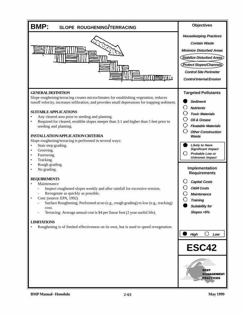
Objectives
Housekeeping Practices
Contain Waste
Minimize Disturbed Areas
Stabilize Disturbed Areas
Protect Slopes/Channels
Control Site Perimeter
Control Internal Erosion
Targeted Pollutants
Sediment
Nutrients
Toxic Materials
Oil & Grease
Floatable Materials
Other ConstructionWaste
Likely to HaveSignificant ImpactProbable Low orUnknown Impact
ImplementationRequirements
Capital Costs
O&M Costs
Maintenance
Training
Suitability for
Slopes >5%
High Low
May 1999BMP Manual - Honolulu 2-63
ESC42
BMP: SLOPE ROUGHENING/TERRACING
GENERAL DEFINITIONSlope roughening/terracing creates microclimates for establishing vegetation, reducesrunoff velocity, increases infiltration, and provides small depressions for trapping sediment.
SUITABLE APPLICATIONS• Any cleared area prior to seeding and planting.• Required for cleared, erodible slopes steeper than 3:1 and higher than 5 feet prior to
seeding and planting.
INSTALLATION/APPLICATION CRITERIASlope roughening/terracing is performed in several ways:• Stair-step grading.• Grooving.• Furrowing.• Tracking.• Rough grading.• No grading.
REQUIREMENTS• Maintenance
- Inspect roughened slopes weekly and after rainfall for excessive erosion.- Revegetate as quickly as possible.
• Cost: (source: EPA, 1992)- Surface Roughening: Performed at no (e.g., rough grading) to low (e.g., tracking)
cost.- Terracing: Average annual cost is $4 per linear foot (2 year useful life).
LIMITATIONS• Roughening is of limited effectiveness on its own, but is used to speed revegetation.

May 1999BMP Manual - Honolulu
ADDITIONAL INFORMATION: SLOPE ROUGHENING/TERRACING
2-64
ESC42
Slope roughening/terracing creates uneven depressions, steps or grooves on the soil surface to aid in establishment ofvegetation, reduce runoff velocity, increase infiltration, and provide for sediment trapping.
Surface roughening may be applied to all slopes steeper than 3:1, and greater than 5 vertical feet, providing some instanterosion protection on bare soil while vegetative cover is being established. It is an inexpensive, simple and short-termerosion control measure for roadway cut slopes.
Terracing usually is a more permanent measure used to stabilize a steep slope. Terraces should be designed by aregistered professional engineer and included in the project construction plans. Local design criteria should be used.
Installation/ApplicationGraded areas with smooth, hard surfaces give a false impression of “finished grading” and a job well done. It is difficultto establish vegetation on such surfaces due to reduced water infiltration and the potential for erosion. Rough slopesurfaces with uneven soil and rocks left in place may appear unattractive or unfinished at first, but they encourage waterinfiltration, speed the establishment of vegetation, and decreased runoff velocity. Rough, loose soil surfaces give lime,fertilizer, and seed some natural coverage. Niches in the surface provide microclimates which generally provide a coolerand more favorable moisture level than hard flat surfaces; this aids seed germination.
There are different methods for achieving a roughened soil surface on a slope, and the selection of an appropriatemethod depends upon the type of slope. Roughening methods include stair-step grading, grooving, and tracking.Factors to be considered in choosing a method are slope steepness, mowing requirements, and whether the slope isformed by cutting or filling.
1. Disturbed areas which will not require mowing may be stair-step graded, grooved, or left rough after filling.2. Graded areas steeper than 3:1 should be stair-stepped with benches (See figure at end of fact sheet). The stair
stepping will help vegetation become attached and also trap soil eroded from the slopes above. Stair-step grading isparticularly appropriate in soils containing large amounts of soft rock. Each “step” catches material which sloughsfrom above, and provides a level site where vegetation can become established. Stairs should be wide enough towork with standard earth moving equipment.
3. Areas which will be mowed (there areas should have slopes less than 3:1) may have small furrows left by disking,harrowing, raking, or seed-planting machinery operated on the contour.
4. It is important to avoid excessive compacting of the soil surface when scarifying. Tracking with bulldozer treads ispreferable to not roughening at all, but is not as effective as other forms of roughening, as the soil surface isseverely compacted and runoff is increased. Tracking can be accomplished in a variety of ways, including “trackwalking,” or driving a crawler tractor up and down the slope, in leaving a pattern of cleat imprints parallel to slopecontours.
REFERENCESBest Management Practices and Erosion Control Manual for Construction Sites, Flood Control District of MaricopaCounty, Arizona, September 1992.
Handbook of Steel, Drainage & Highway Construction, American Iron and Steel Institute, 1983.
Proposed Guidance Specifying Management Measures for Sources of Nonpoint Pollution in Coastal Waters, WorkGroup Working Paper, USEPA, April, 1992.
Stormwater Management Water for the Puget Sound Basin, Washington State Department of Ecology,The Technical Manual - February 1992, Publication # 91-75.

May 1999BMP Manual - Honolulu
ADDITIONAL INFORMATION: SLOPE ROUGHENING/TERRACING
2-65
ESC42STAIR-STEPPING CUT SLOPES
AND GROOVING SLOPES
40” - 50”
DEBRIS FROM SLOPEABOVE IS CAUGHT BY STEPS
DRAINAGE
10 30” -
40”
WATER, SOIL, AND FERTILIZERARE HELD BY STEPS - PLANTSCAN BECOME ESTABLISHED ONTHE STEPS.
STAIR STEPPING CUT SLOPES
12” - 15”
3”GROOVING IS CUTTING FURROWSALONG THE CONTOUR OF A SLOPE.IRREGULARITIES IN THE SOIL SUR-FACE CATCH RAINWATER AND PRO-VIDE SOME COVERAGE OF THE LIME,FERTILIZER AND SEED.
GROOVING SLOPES
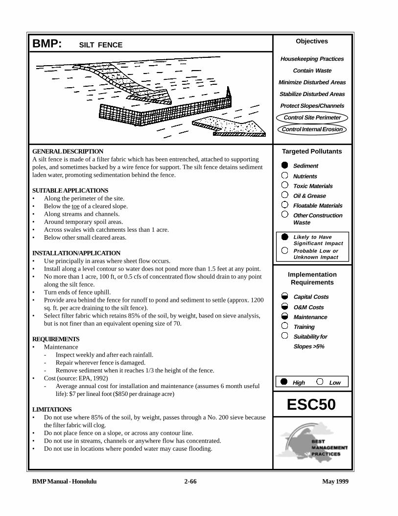
Objectives
Housekeeping Practices
Contain Waste
Minimize Disturbed Areas
Stabilize Disturbed Areas
Protect Slopes/Channels
Control Site Perimeter
Control Internal Erosion
Targeted Pollutants
Sediment
Nutrients
Toxic Materials
Oil & Grease
Floatable Materials
Other ConstructionWaste
Likely to HaveSignificant ImpactProbable Low orUnknown Impact
ImplementationRequirements
Capital Costs
O&M Costs
Maintenance
Training
Suitability for
Slopes >5%
High Low
BMP Manual - Honolulu May 19992-66
ESC50
BMP: SILT FENCE
GENERAL DESCRIPTIONA silt fence is made of a filter fabric which has been entrenched, attached to supportingpoles, and sometimes backed by a wire fence for support. The silt fence detains sedimentladen water, promoting sedimentation behind the fence.
SUITABLE APPLICATIONS• Along the perimeter of the site.• Below the toe of a cleared slope.• Along streams and channels.• Around temporary spoil areas.• Across swales with catchments less than 1 acre.• Below other small cleared areas.
INSTALLATION/APPLICATION• Use principally in areas where sheet flow occurs.• Install along a level contour so water does not pond more than 1.5 feet at any point.• No more than 1 acre, 100 ft, or 0.5 cfs of concentrated flow should drain to any point
along the silt fence.• Turn ends of fence uphill.• Provide area behind the fence for runoff to pond and sediment to settle (approx. 1200
sq. ft. per acre draining to the silt fence).• Select filter fabric which retains 85% of the soil, by weight, based on sieve analysis,
but is not finer than an equivalent opening size of 70.
REQUIREMENTS• Maintenance
- Inspect weekly and after each rainfall.- Repair wherever fence is damaged.- Remove sediment when it reaches 1/3 the height of the fence.
• Cost (source: EPA, 1992)- Average annual cost for installation and maintenance (assumes 6 month useful
life): $7 per lineal foot ($850 per drainage acre)
LIMITATIONS• Do not use where 85% of the soil, by weight, passes through a No. 200 sieve because
the filter fabric will clog.• Do not place fence on a slope, or across any contour line.• Do not use in streams, channels or anywhere flow has concentrated.• Do not use in locations where ponded water may cause flooding.

May 1999BMP Manual - Honolulu
ADDITIONAL INFORMATION: SILT FENCE
2-67
ESC50
A silt fence is a temporary sediment barrier consisting of filter fabric stretched across and attached to supporting posts,entrenched, and, depending upon the strength of the fabric used, supported with wire fence. Silt fences trap sediment intwo ways: (1) by intercepting and detaining small amounts of sediment from disturbed areas during constructionoperations, in order to promote sedimentation behind the fence; and (2) by decreasing the velocity of low flows (up to0.5 cfs) in swales.
Silt fences may be used for perimeter control, placed upstream of the point(s) of discharge of sheet flow from a site. Theymay also be used as interior controls below disturbed areas where runoff may occur in the form of sheet and rill erosion,and perpendicular to minor swales or ditch lines for up to one acre contributing drainage areas. Silt fences are generallyineffective in locations where the flow is concentrated and are only applicable for sheet or overland flows.
Installation/ApplicationPlanning:Silt fences are generally most effective when the following placement criteria are followed:
• Limit the upstream drainage area to 1 acre or less when used alone or in combination with sediment basin in a largersite.
• The maximum slope perpendicular to the fence line should be 1:1.• Limit the maximum sheet or overland flow path length to any point along the fence to 100 feet.• Limit the concentrated flows reaching the fence to 0.5 cfs.
Silt fences are preferable to straw barriers in many cases. Laboratory work at the Virginia Highway and TransportationResearch Council has shown that silt fences can trap a much higher percentage of suspended sediments than can strawbales. While the failure rate of silt fences is lower than that of straw barriers, there are many instances where silt fenceshave been improperly installed. The following installation methods can improve performance and should be followed:
• Construct the silt fence along a level contour.• Silt fences should remain in place until the disturbed area is permanently stabilized.• Provide sufficient room for runoff to pond behind the fence and to allow sediment removal equipment to pass
between the silt fence and toes of slopes or other obstructions. About 1200 sq. ft. of ponding area should beprovided for every acre draining to the fence.
• Turn the ends of the filter fence uphill to prevent storm water from flowing around the fence.• Leave an undisturbed or stabilized area immediately downslope from the fence.• Do not place in live streams or intermittently flowing channels.
Design:Selection of a filter fabric is based on soil conditions at the construction site (which affect the equivalent opening size(EOS) fabric specification) and characteristics of the support fence (which affect the choice of tensile strength). Thedesigner should specify a filter fabric that retains the soil found on the construction site yet will have openings largeenough to permit drainage and prevent clogging. The following criteria is recommended for selection of the equivalentopening size:
1. If 50 percent or less of the soil, by weight, will pass the U.S. standard sieve No. 200, select the EOS to retain 85percent of the soil. The EOS should not be finer than EOS 70.
2. For all other soil types, the EOS should be no larger than the openings in the U.S. Standard Sieve No. 70[0.0083 in. (0.21 mm.)] except where direct discharge to a stream, lake, or wetland will occur, then the EOSshould be no larger than Standard Sieve No. 100.

May 1999BMP Manual - Honolulu
ADDITIONAL INFORMATION: SILT FENCE
2-68
ESC50
To reduce the chance of clogging, it is preferable to specify a fabric with openings as large as allowed by the criteria. Nofabric should be specified with an EOS smaller than U.S. Standard Sieve No. 100 [0.0059 in. (0. 15 mm.)]. If 85 percentor more of a soil, by weight, passes through the openings in a No. 200 sieve [0.0029 in. (0.074 mm.)], filter fabric shouldnot be used. Most of the particles in such a soil would not be retained if the EOS was too large, and they would clog thefabric quickly if the EOS was small enough to capture the soil.
The fence should be supported by a wire mesh if the fabric selected does not have sufficient strength and burstingstrength characteristics for the planned application ( as recommended by the fabric manufacturer). Filter fabric materialshould contain ultraviolet ray inhibitors and stabilizers to provide a minimum of six months of expected usable construc-tion life at a temperature range of 0º F. to 120º F.
Installation Guidelines:Filter fences are to be constructed on a level contour. Sufficient area should exist behind the fence for ponding to occurwithout flooding or overtopping the fence.
• Posts should be spaced a maximum of 6 feet apart and driven securely into the ground a minimum of 30 inches.• A trench should be excavated approximately 8 inches wide and 12 inches deep along the line of posts and upslope
from the barrier.• When standard strength filter fabric is used, a wire mesh support fence should be fastened securely to the upslope
side of the posts using heavy-duty wire staples at least 1 inch long, tie wires or hog rings. The wire should extendinto the trench a minimum of 4 inches.
• The standard strength filter fabric should be stapled or wired to the fence, and 40 inches of the fabric should extendinto the trench. When extra-strength filter fabric and closer post spacing are used, the wire mesh support fence maybe eliminated and the filter fabric stapled or wired directly to the posts.
• Avoid the use of joints. The filter fabric should be purchased in a continuous roll, then cut to the length of thebarrier. When joints are necessary, filter cloth should be spliced together only at a support post, with a minimum 6inch overlap, and both ends securely fastened to the post
• The trench should be backfilled with compacted native material.
RequirementsMaintenance:
Inspect monthly during dry periods and immediately after each rainfall. Repair as necessary. Sediment must be removedwhen it reaches approximately one third the height of the fence, especially if heavy rains are expected.
Filter fences should not be removed until the upslope area has been permanently stabilized.
Limitations• Filter fences will create a temporary sedimentation pond on the upstream side of the fence and may cause temporary
flooding. Fences not constructed on a level contour will be overtopped by concentrated flow resulting in failure ofthe filter fence.
• Filter fences are not practical where large flows of water are involved, hence the need to restrict their use to drainageareas of one acre or less, and flow rates of less than 0.5 cfs.
• Problems may arise from incorrect selection of pore size and/or improper installation.• Do not allow water depth to exceed 1.5 ft. at any point.• Improperly installed fences are subject to failure from undercutting, overlapping, or collapsing.

May 1999BMP Manual - Honolulu
ADDITIONAL INFORMATION: SILT FENCE
2-69
ESC50
REFERENCESBest Management Practices and Erosion Control Manual for Construction Sites, Flood Control District of MaricopaCounty, Arizona, September 1992.
Environmental Action Manual, City of Austin, Texas, 1989.
Manual of Standards of Erosion and Sediment Control Measures, Association of Bay Area Governments, June 1981.
Proposed Guidance Specifying Management Measures for Sources of Nonpoint Pollution in Coastal Waters, WorkGroup Working Paper, USEPA, April, 1992.
Sedimentation and Erosion Control Practices, An Introductory of Current Practices (Draft), USEPA, 1990.
Stormwater Management Manual for The Puget Sound Basin, Washington State Department of Ecology, Public ReviewDraft, 1991.
Water Quality Management Plan for the Lake Tahoe Region, Volume II, Handbook of Management Practices, TahoeRegional Planning Agency - November 1988.

May 1999BMP Manual - Honolulu
ADDITIONAL INFORMATION: SILT FENCE
2-70
ESC50
SILT FENCE
30”
12”
6”
12”
8”
18”
24”
60”
24”
6”6’ MAX.
2” X 4” WOOD POST, STANDARD OR BETTEROR EQUAL ALTERNATE: STEEL FENCE POST
FILTER FABRIC MATERIAL 60” WIDE ROLLS.USE STAPLES OR WIRE RINGS TO ATTACHFABRIC TO WIRE.
2” X 2” 14 GAGE WIREFABRIC OR EQUIVALENT
BURY BOTTOM OF FILTER MATERIALIN 8” X 12” TRENCH
FILTER FABRIC MATERIAL
BACKFILL AND COMPACT THE EXCAVATEDSOIL IN TRENCH AND ON BOTH SIDES OFFILTER FENCE FABRIC
2” X 2” 14 GAGE WIREFABRIC OR EQUIVALENT
FOLD AND SET FILTERFABRIC INTO SOIL
2” X 4” WOOD POSTALT.: STEEL FENCE POSTS
FLOW

Objectives
Housekeeping Practices
Contain Waste
Minimize Disturbed Areas
Stabilize Disturbed Areas
Protect Slopes/Channels
Control Site Perimeter
Control Internal Erosion
Targeted Pollutants
Sediment
Nutrients
Toxic Materials
Oil & Grease
Floatable Materials
Other ConstructionWaste
Likely to HaveSignificant ImpactProbable Low orUnknown Impact
ImplementationRequirements
Capital Costs
O&M Costs
Maintenance
Training
Suitability for
Slopes >5%
High Low
May 1999BMP Manual - Honolulu 2-71
ESC52
BMP: SAND BAG BARRIER
GENERAL DEFINITIONStacking sand bags along a level contour creates a barrier which detains sediment-ladenwater, ponding water upstream of the barrier and promoting sedimentation.
SUITABLE APPLICATIONS• Along the perimeter of the site.• Check dams across streams and channels.• Along streams and channels.• Barrier for utility trenches in a channel.• Across swales with small catchments.• Division dike or berm.• Below the toe of a cleared slope.• Create a temporary sediment trap.• Around temporary spoil areas.• Below other small cleared areas.
INSTALLATION/APPLICATION CRITERIA• May be used in drainage areas up to 5 acres.• Install along a level contour.• Base of sand bag barrier should be at least 48 inches wide.• Height of sand bag barrier should be at least 18 inches high.• 4 inch PVC pipe may be installed between the top layer of sand bags to drain large
flood flows.• Provide area behind barrier for runoff to pond and sediment to settle, size according to
sediment trap BMP criteria (ESC55).• Place below the toe of a slope.• Use sand bags large enough and sturdy enough to withstand major flooding.
REQUIREMENTS• Maintenance
- Inspect after each rain.- Reshape or replace damaged sand bags immediately.- Remove sediment when it reaches six inches in depth.
• Cost- Sand bag barriers are more costly, but typically have a longer useful life than other
barriers.
LIMITATIONS• Sand bags are more expensive than other barriers, but also more durable.• Burlap should not be used for sand bags.

May 1999BMP Manual - Honolulu
ADDITIONAL INFORMATION: SAND BAG BARRIER
2-72
ESC52
Suitable ApplicationsSand bag berms may be used during construction activities in stream beds and utility construction in channels, tempo-rary channel crossing for construction equipment, etc. Sand bag berms may also be installed parallel to roadwayconstruction. Sand bag berms may also be used to create temporary sediment traps, retention basins and in place ofstraw bales or silt fences. Examples of applications include:• Check dams across stream channels.• Barriers for utility trenches or other construction in a stream channel.• At temporary channel crossings.• May be used on a slope where straw bales and silt fences are not appropriate.• As a diversion dike.• Embankment for a temporary sediment basin or retention basin.• Sediment barriers near the toe of slopes.• At construction perimeter.• Permits may be required from the US Army Corps of Engineers and Department of Land and Natural Resources.
Advantages• Provides a semi-permeable barrier in potentially wet areas.• More permanent than silt fences or straw bales.• Allows for easy relocation on site to meet changing needs during construction.
Installation/ApplicationSand bag barriers my be used for sediment trapping in locations where silt fences and straw bale barriers are not strongenough. In addition, sand bag barriers are appropriate to use when construction of check dams or sumps in a stream isundesirable. The sand bag berms can provide the same function as a check dam without disturbing the stream orvegetation. The sand bag berm will also allow a small sediment retention area to be created prior to construction of finaldetention basins. For installation of a sand bag berm, the following criteria should be observed:
• Drainage Area - Up to five (5) acres.• Height of Berm - 18 inches minimum height, measured from the top of the existing ground at the upslope toe to the
top of the barrier.• Width of Berm - 48 inches minimum width measured at the bottom of the barrier, 18 inches at the top.• Sand bag Size - Length 24 to 30 inches, width 16 to 18 inches and thickness six (6) to eight (8) inches. Weight 90 to
125 pounds.• Sand bag Material - Polypropylene, polyethylene or polyamide woven fabric, minimum unit weight four (4) ounces
per square yard, mullen burst strength exceeding 300 psi and ultraviolet stability exceeding 70 percent.• Use of burlap is discouraged since it rots and deteriorates easily.• Grade of Sand - Coarse sand, gravel.• Runoff water should be allowed to flow over the tops of the sand bags or through four (4) inch polyvinyl
chloride pipes embedded below the top layer of bags.• Area behind the sand bag barrier should be established according to sizing criteria for sediment trap BMP (ESC55).
REFERENCESBest Management Practices and Erosion Control Manual for Construction Sites, Flood Control District of MaricopaCounty, Arizona. September 1992.
Water Quality Management Plan for the Late Tahoe Region, Volume II, Handbook of Management Practices, TahoeRegional Planning Agency - November 1988.
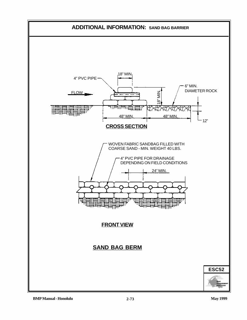
May 1999BMP Manual - Honolulu
ADDITIONAL INFORMATION: SAND BAG BARRIER
2-73
ESC52
18” MIN.
CROSS SECTION
WOVEN FABRIC SANDBAG FILLED WITHCOARSE SAND - MIN. WEIGHT 40 LBS.
SAND BAG BERM
FRONT VIEW
4” PVC PIPE FOR DRAINAGEDEPENDING ON FIELD CONDITIONS
12”
18” M
IN.
48” MIN.48” MIN.
24” MIN.
FLOW
4” PVC PIPE
6” MIN.DIAMETER ROCK

Objectives
Housekeeping Practices
Contain Waste
Minimize Disturbed Areas
Stabilize Disturbed Areas
Protect Slopes/Channels
Control Site Perimeter
Control Internal Erosion
Targeted Pollutants
Sediment
Nutrients
Toxic Materials
Oil & Grease
Floatable Materials
Other ConstructionWaste
Likely to HaveSignificant ImpactProbable Low orUnknown Impact
ImplementationRequirements
Capital Costs
O&M Costs
Maintenance
Training
Suitability for
Slopes >5%
High Low
BMP Manual - Honolulu May 19992-74
ESC53
BMP: BRUSH OR ROCK FILTER
GENERAL DEFINITIONA rock filter berm is made of rock 3/4 to 3 inches in diameter and placed along a levelcontour where sheet flow may be detained and ponded, promoting sedimentation. A brushbarrier is composed of brush (usually obtained during the site clearing) wrapped in filtercloth and anchored to the toe of the slope. If properly anchored brush or rock filters may beused for sediment trapping and velocity reduction. See Check Dam BMP (ESC41) for moreinformation.
SUITABLE APPLICATIONSAs check dams across mildly sloped construction roads. Below the toe of slopes. Alongthe site perimeter. Along streams and channels. Around temporary spoil areas. Below othersmall cleared areas. At sediment traps at culvert/pipe outlets.
INSTALLATION/APPLICATION CRITERIA• Use principally in areas where sheet or rill flow occurs.• For rock filter, use larger rock and place in a staked, woven wire sheathing if placed
where concentrated flows occur.• Install along a level contour.• Leave area behind berm where runoff can pond and sediment can settle.• Drainage area should not exceed 5 acres.
REQUIREMENTS• Maintenance
- Inspect monthly and after each rainfall.- If berm damaged, reshape and replace lost/dislodged rock.- Remove sediments when depth reaches 1/3 of berm height, or 1 ft.
• Cost- Brush filter: Low to moderate cost if debris from on-site clearing and grubbing is
used.- Rock filter: Expensive, since off-site materials, hand construction and demolition/
removal are usually required.

May 1999BMP Manual - Honolulu
BMP: BRUSH OR ROCK FILTER (Continue)
2-75
ESC53
LIMITATIONS• Rock berms may be difficult to remove.• Removal problems limit their usefulness in landscaped areas.• Not appropriate for drainage areas greater than 5 acres.• Runoff will pond upstream of the filter, possibly causing flooding if sufficient space does not exist.

May 1999BMP Manual - Honolulu
ADDITIONAL INFORMATION: BRUSH OR ROCK FILTER
2-76
ESC53
Rock FilterA rock filter consists of open graded rock installed at the toe of a slope, along the perimeter of a developing or disturbedarea, and as a checkdam across construction roads. Their purpose is to intercept sediment laden runoff from disturbedareas of the site, allow the runoff to pond, promote sedimentation behind the filter, and slowly release the water as sheetflow.
Rock filters are appropriate where a temporary measure is needed to prevent sediments from entering right-of-ways oftraffic areas such as near the toe of slopes, incorporated into temporary stabilized construction entrances (ESC26), or atother locations along the construction site perimeter. Rock filters may also be used as check dams across one or morelanes of construction traffic temporary roads, or unsurfaced rights of way subject to construction traffic.
Advantages of the rock filters are that they may be less costly than other temporary barriers, and are relatively efficientat sediment removal.
Installation/ApplicationPlanning:• Rock filters should be placed along a level contour to intercept sheet flow.• Allow ample room for ponding, sedimentation, and access by sediment removal equipment between the berm and
the toes of slopes.• Flow through the filter should occur as sheet flow into an undisturbed or stabilized area.• Installation in stream beds requires large rock, staking of woven wire sheathing, and daily inspection.
Design & Sizing Criteria.The following design criteria are commonly used to construct filters:• In Non-Traffic Areas:
- Maximum flow-through rate per square foot of filter = 60 gpm- Height = 18 inches minimum- Top width = 24 inches minimum- Side slopes = 2:1 or flatter- Woven wire sheathing (poultry netting) is recommended in areas of concentrated flow. The wire should be 1
inch diameter hexagonal mesh, galvanized 20 gauge.- Build the filter along on a level contour.- Rock: 3/4 to 3 inches open graded for sheet flow, 3 to 5 inches open graded for concentrated flow.
• In Construction Traffic Areas:- Height = 12" maximum- Provide multiple filters in series, spaced as shown.
Every 300 ft on slopes less than 5 percentEvery 200 ft on slopes 5 to 10 percentEvery 100 ft on slopes greater than 10 percent.
Brush FilterBrush filters trap and filter sediments in a manner similar to other barriers in this handbook (e.g., silt fence, straw balebarrier, rock filter), but have the advantage of being constructed from brush cleared from the site and usually disposedoff-site at a cost.

May 1999BMP Manual - Honolulu
ADDITIONAL INFORMATION: BRUSH OR ROCK FILTER
2-77
ESC53
Steps in Construction of a Brush Filter:1. Stack the brush at the toe of a slope or along the perimeter of the site just outside the limits of clearing and grab-
bing. The brush may be stacked up to 15 ft. high and 15 ft. wide.2. Construct a trench 1 to 3 ft. deep immediately upslope from the brush.3. Place filter fabric over the brush filter and in the trench, extending 1 to 2 ft upslope of the trench.4. Backfill the trench with aggregate or compacted soil. The trench should be deep enough and backfill material
sufficient to hold the barrier in place during a storm.
REFERENCESBest Management Practices and Erosion Control Manual for Construction Sites, Flood Control District of MaricopaCounty, Arizona, September, 1992.
Handbook of Steel Drainage & Highway Construction, American Iron and Steel Institute, 1983.
Stormwater Management Water for the Puget Sound Basin, Washington State Department of Ecology, The TechnicalManual - February 1992, Publication # 91-75.
Storm Water Pollution Plan Handbook, First Edition, State of California. Department of Transportation Division of NewTechnology, Materials and Research, October 1992.

May 1999BMP Manual - Honolulu
ADDITIONAL INFORMATION: BRUSH OR ROCK FILTER
2-78
ESC53GRAVEL FILTER BERM
6’
¾” - 3”CRUSHED ROCK 1.5’ FOR NON TRAFFIC AREAS
1.0’ FOR TRAFFIC AREAS
FLOW
¾” - 3”CRUSHED ROCKGRAVEL BERM
TRAFFIC AREAS
PLAN

Objectives
Housekeeping Practices
Contain Waste
Minimize Disturbed Areas
Stabilize Disturbed Areas
Protect Slopes/Channels
Control Site Perimeter
Control Internal Erosion
Targeted Pollutants
Sediment
Nutrients
Toxic Materials
Oil & Grease
Floatable Materials
Other ConstructionWaste
Likely to HaveSignificant ImpactProbable Low orUnknown Impact
ImplementationRequirements
Capital Costs
O&M Costs
Maintenance
Training
Suitability for
Slopes >5%
High Low
May 1999BMP Manual - Honolulu 2-79
ESC54
BMP: STORM DRAIN INLET PROTECTION
GENERAL DEFINITIONDevices of various designs which detain sediment-laden runoff and allow the sediment it tosettle prior to discharge into a storm drain inlet or catch basin.
SUITABLE APPLICATIONS• Every storm drain inlet receiving sediment-laden runoff should be protected, either by
covering the inlet or promoting sedimentation upstream of the inlet.
INSTALLATION/APPLICATION• Five types of inlet protection are presented below, however, it is recognized that other
effective methods and proprietary devices exist and may be selected:- Filter Fabric Fence: Appropriate for drainage basins less than one acre with
less than a 5 percent slope.- Block and Gravel Filter: Appropriate for flows greater than 0.5 cfs.- Gravel and Wire Mesh Filter: Used on curb or drop inlets where construction
equipment may drive over the inlet.- Sand bag barrier: Used to create a small sediment trap upstream of inlets on
sloped, paved streets.- Excavated Drop Inlet Sediment Trap: An excavated area around the inlet to
trap sediment (see Sediment Trap ESC55).• Select the appropriate type of inlet protection and design as referred to or as described
in this fact sheet.• Use only for drainage areas smaller than one acre unless a sediment trap first inter-
cepts the runoff.• Provide area around the inlet for water to pond without flooding structures and
property.
REQUIREMENTS• Maintenance
- Inspect weekly and after each rain.- Replace clogged filter fabric or stone filters immediately.- Remove sediment when depth exceeds half the height of the filter, or half the
depth of the sediment trap.- Remove as soon as upstream soils are stabilized and streets are swept.
• Cost (source: EPA, 1992)- Average annual cost for installation and maintenance (1 year useful life) is $150
per inlet.

May 1999BMP Manual - Honolulu
BMP: STORM DRAIN INLET PTOTECTION (Continue)
2-80
ESC54
LIMITATIONS• Drainage area should not exceed 1 acre.• Runoff will bypass protected inlets on slopes.• Ponding will occur at a protected inlet, with possible short-term flooding.• Straw bales are not effective for inlet protection.

May 1999BMP Manual - Honolulu
ADDITIONAL INFORMATION: STORM DRAIN INLET PROTECTION
2-81
ESC54
Storm drain inlet protection consists of a sediment filter or an impounding area around or upstream of a storm drain, dropinlet, or curb inlet. This erosion and sedimentation control BMP prevents excessive sediment from entering stormdrainage systems prior to permanent stabilization of the disturbed area.
All on-site storm drain inlets should be protected. Off-site, inlets should be protected in areas where construction activitytracks sediment onto paved areas or where inlets receive runoff from disturbed areas.
Installation/Application CriteriaPlanningLarge amounts of sediment may enter the storm drain system when storm drains are installed before the upslope drainagearea is stabilized, or where construction is adjacent to an existing storm drain. In cases of extreme sediment loading, thestorm drain itself may clog and lose a major portion of its capacity. To avoid these problems, it is necessary to preventsediment from entering the system at the inlets.Inlet control measures presented in this handbook should not be used for inlets draining more than one acre. Runoff fromlarger disturbed areas should be first routed through a temporary Sediment Trap (see ESC56). Different types of inletprotection are appropriate for different applications depending on site conditions and the type of inlet. Inlet protectionmethods not presented in this handbook should be approved by the City.
General Design and sizing criteria:• Grates and spaces around all inlets should be scaled to prevent seepage of sediment-laden water.• Excavate sediment sumps (where needed) 1 to 2 feet with 2:1 side slopes around the inlet.
Installation procedures for filter fabric fence:a. Place 2 inch by 2 inch wooden stakes around the perimeter of the inlet a maximum of 3 feet apart and drive them at
least 8 inches into the ground. The stakes must be at least 3 feet long.b. Excavate a trench approximately 8 inches wide and 12 inches deep around the outside perimeter of the stakes.c. Staple the filter fabric (for materials and specifications, see Silt Fence ESC50) to wooden stakes so that 32 inches of
the fabric extends out and can be formed into the trench. Use heavy-duty wire staples at least one inch in length.d. Backfill the trench with 3/4 inch or less washed gravel all the way around.
Installation procedure for block and gravel filter:a. Place hardware cloth or comparable wire mesh with one-half inch openings over the drop inlet so that the wire extends
a minimum of 1 foot beyond each side of the inlet structure. If more than one strip is necessary, overlap the strips. Placefilter fabric over the wire mesh.
b. Place concrete blocks lengthwise on their sides in a single row around the perimeter of the inlet, so that the open endsface outward, not upward. The ends of adjacent blocks should abut. The height of the barrier can be varied, dependingon design needs, by stacking combinations of blocks that are 4 inches, 8 inches, and 12 inches wide. The row of blocksshould be at least 12 inches but no greater than 24 inches high.
c. Place wire mesh over the outside vertical face (open end) of the concrete blocks to prevent stone from being washedthrough the blocks. Use hardware cloth or comparable wire mesh with one half inch openings.
d. Pile washed stone against the wire mesh to the top of the blocks. Use 3/4 to 3 inch gravel.
Installation procedure for gravel and wire mesh filters:a. Place wire mesh over the drop inlet so that the wire extends a minimum of 1 foot beyond each side of the inlet structure.
Use hardware cloth or comparable wire mesh with one-half inch openings. If more than one strip of mesh is necessary,overlap the strips. Place filter fabric over wire mesh.

May 1999BMP Manual - Honolulu
ADDITIONAL INFORMATION: STORM DRAIN INLET PROTECTIN
2-82
ESC54
b. Place 3/4 to 3 inch gravel over the filter fabric/wire mesh. The depth of the gravel should be at least 12 inches overthe entire inlet opening (see attached figure).
Installation procedure for sand bag barrier:a. Use sand bag made of geotextile fabric (not burlap), and fill with 3/4 in. rock or 1/4 in. pea gravel.b. Construct on gently sloping street.c. Leave room upstream of barrier for water to pond and sediment to settle.d. Place several layers of sand bags -- overlapping the bags and packing them tightly together.e. Leave gap of one bag on the top row to serve as a spillway. Flow from a severe storm (e.g., 10-year storm) should
not overtop the curb.
Maintenance Requirements• For filter fabric fences: Inspections should be made on a regular basis, especially after large storm events. If the
fabric becomes clogged, it should be replaced. Sediment should be removed when it reaches approximately one-halfthe height of the fence. If a sump is used, sediment should be removed when it fills approximately one-half the depthof the hole.
• For gravel filters: If the gravel becomes clogged with sediment, it must be carefully removed from the inlet, and eithercleaned or replaced. Since cleaning gravel at a construction site may be difficult, use the sediment-laden stoneinstead as fill and put fresh stone around the inlet.
• The inlet protection should be removed 30 days after the upslope area has been fully stabilized. Any sedimentaround the inlet must be carefully removed and disposed.
REFERENCESBest Management Practices and Erosion Control Manual for Construction Sites, Flood Control District of MaricopaCounty, Arizona, September, 1992.
“Draft - Sedimentation and Erosion Control, An Inventory of Current Practices”, U.S.E.P.A., April, 1990.
Erosion and Sediment Control Handbook, S.J. Goldman, K. Jackson, T.A. Bursetynsky, P.E., McGraw Hill Book Company.
Manual of Standards of Erosion and Sediment Control Measures, Association of Bay Area Governments, June 1981.
Proposed Guidance Specifying Management Measures for Sources of Nonpoint Pollution in Coastal Waters, WorkGroup Working Paper, USEPA, April, 1992.
Stormwater Management Water for the Puget Sound Basin, Washington State Department of Ecology, The TechnicalManual - February 1992, Publication # 91-75.
Storm Water Pollution Prevention Handbook, First Edition, State of California, Department of Transportation Division ofNew Technology, Materials, and Research, October 1992.

May 1999BMP Manual - Honolulu
ADDITIONAL INFORMATION: STORM DRAIN INLET PROTECTION
2-83
ESC54
STAKES
DROP INLET WITH GRATE
FILTER FABRIC
BURIED FILTER FABRIC
DROP INLET
WASHED GRAVEL
FILTER FABRIC
STAKES
SEDIMENT LADENRUNOFF
PROFILE
FILTER FABRIC FENCE DROP INLET FILTER
STRAW BALE BARRIERS24
”
20”
12”
8”
8”
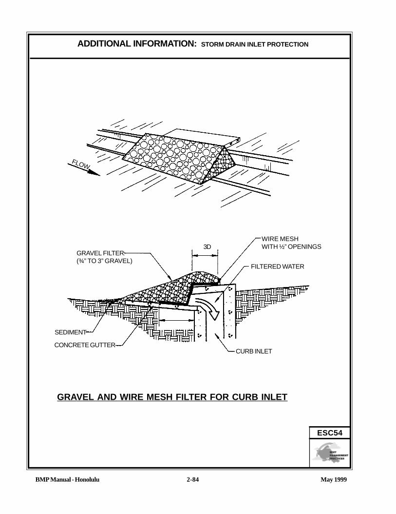
May 1999BMP Manual - Honolulu
ADDITIONAL INFORMATION: STORM DRAIN INLET PROTECTION
2-84
ESC54
GRAVEL AND WIRE MESH FILTER FOR CURB INLET
3D
FLOW
CONCRETE GUTTER
SEDIMENT
GRAVEL FILTER(¾” TO 3” GRAVEL)
FILTERED WATER
WIRE MESHWITH ½” OPENINGS
CURB INLET

May 1999BMP Manual - Honolulu
ADDITIONAL INFORMATION: STORM DRAIN INLET PROTECTION
2-85
ESC54EXCAVATED DROP INLET SEDIMENT TRAP
MAX. SLOPE 2:1
DROP INLET
ASREQUIRED
SEDIMENT-LADEN RUNOFF
*STO
RAGE AREA
STORM WATER WITHLARGER PARTICLESREMOVED
LARGER PARTICLESSETTLE OUT
DEPTH BELOW TOP OF INLET:MIN. 1” - MAX. 2’
* STORAGE VOLUME =600 CU. FT. PERDISTURBED DRAINAGE.
THIS METHOD OF INLET PROTECTION IS APPLICABLE WHERE HEAVY FLOWSARE EXPECTED AND WHERE AND OVERFLOW CAPABILITY AND EASE OFMAINTENANCE ARE DESIRABLE.

May 1999BMP Manual - Honolulu
ADDITIONAL INFORMATION: STORM DRAIN INLET PROTECTION
2-86
ESC54
GRAVEL AND WIRE MESH FILTERFOR DROP INLET
WIRE MESH WITH ½” OPENINGS
CONCRETE BLOCKGRAVEL FILTER(¾” TO 3” GRAVEL)
WIRE MESHDROP INLET WITH GRATE
OVERFLOW
FILTERED WATER
RUNOFF WATERWITH SEDIMENT
SEDIMENT
18” MIN.
BLOCK AND GRAVEL FILTER AT DROP INLET
RUNOFF WATERWITH SEDIMENT
18” MIN.
¾” TO 3” GRAVEL(12” MIN. DEPTH)
WIRE MESH (½”OPENINGS) WITHFILTER FABRICON TOP
FILTERED WATER
SEDIMENT

Objectives
Housekeeping Practices
Contain Waste
Minimize Disturbed Areas
Stabilize Disturbed Areas
Protect Slopes/Channels
Control Site Perimeter
Control Internal Erosion
Targeted Pollutants
Sediment
Nutrients
Toxic Materials
Oil & Grease
Floatable Materials
Other ConstructionWaste
Likely to HaveSignificant ImpactProbable Low orUnknown Impact
ImplementationRequirements
Capital Costs
O&M Costs
Maintenance
Training
Suitability for
Slopes >5%
High Low
May 1999BMP Manual - Honolulu 2-87
ESC55
BMP: SEDIMENT TRAP
GENERAL DEFINITIONA sediment trap is a small, excavated or bermed area where runoff from small drainage areasis detained and sediment can settle.
SUITABLE APPLICATIONS• Any disturbed area less than 5 acres. (Sediment Basin, ESC56, must be used for
drainage areas greater than 5 acres).• Along the perimeter of the site at locations where sediment-laden runoff is discharged
off-site.• Around and/or upslope from storm drain inlet protection measures.• At any point within the site where sediment-laden runoff can enter stabilized or natural
areas or waterways.
INSTALLATION/APPLICATION CRITERIA• Build outside the area to be graded before clearing, grubbing, and grading begin.• Locate where the trap can be easily cleared of sediment.• Trap size depends on the type of soil, size of the drainage area, and desired sediment
removal efficiency.• The larger the trap, the less frequently sediment must be removed.• The outlet of the trap must be stabilized with rock, vegetation, or another suitable
material.• A stable emergency spillway must be installed to safely convey major floods (see City
drainage requirements).
REQUIREMENTS• Maintenance
- Remove sediment when the sediment storage zone is no more than 1 ft. from beingfull.
- Inspect weekly and after each rain.• Cost (source: EPA, 1992)
- Average annual cost per installation and maintenance (18 month useful life) is$0.70 per ft.3 ($1,300 per drainage acre).
LIMITATIONS• Only use for drainage areas up to 5 acres (see Sediment Basin ESC56 for largerareas).• Only removes coarse sediment (medium silt size and larger) unless sized like a sedimen-
tation basin.

May 1999BMP Manual - Honolulu
ADDITIONAL INFORMATION: SEDIMENT TRAP
2-88
ESC55
A sediment trap is a small temporary ponding area, usually with a gravel outlet, formed by excavation and/or by construct-ing an earthen embankment. Its purpose is to collect and store sediment from sites cleared and/or graded during construc-tion. It is intended for use on small drainage areas, with no unusual drainage features, and projected for a quick build-outtime. It should help in removing coarse sediment from runoff. The trap is a temporary measure with a design life ofapproximately 6 months, and is to be maintained until the site area is permanently protected against erosion by vegetationand/or structures.
Application CriteriaPlanning:Sediment traps should be used only for small drainage areas. If the contributing drainage area is greater than 5 acres, referto Sediment Basin (ESC56), or subdivide the catchment area into smaller drainage basins.
Sediment usually must be removed from the trap after each rainfall event. The SWPPP should detail how this sediment is tobe disposed of, such as for in fill areas on-site, or removal to an approved off-site dump. Sediment traps used as a perimetercontrol should be installed before any land disturbance takes place in the drainage area.
Sediment traps are usually small enough that a failure of the structure would not result in a loss of life, damage to home orbuildings, or interruption in the use of public roads or utilities. Also, sediment traps are attractive to children and can bedangerous. The following recommendations should be implemented to reduce risks.
1. Install continuous fencing around the sediment trap or pond. Consult local ordinancesregarding requirements for maintaining health and safety.
2. Restrict basin side slopes to 3:1 or flatter.
Design:Sediment trap size depends on the type of soil, size of the drainage area, and desired sediment removal efficiency (seeSediment Basin ESC56). As a rule of thumb, the larger the basin volume the greater the sediment removal efficiency.Sizing criteria have been established in the “Rules Relating to Soil Erosion Standards and Guidelines.” The sizing criteriabelow assume that this runoff volume is one inch-acre of runoff per acre. The following criteria should trap moderate tohigh amounts of sediment in most areas.• Trap settling volume at least 133 cu. yd. per acre.• Trap sediment storage volume at least 33 cu. yd. per acre (note: the larger this volume, the less frequently the trap
must be cleaned out).• Trap length greater than twice the basin width.• Flood volume large enough to contain a major flood without upstream damage and overtopping the embankment.
InstallationSediment traps can be constructed by excavating a depression in the ground or creating an impoundment with a barrier orlowhead dam. Sediment traps should be installed outside the area being graded and should be built prior to the start of thegrading activities or removal of vegetation. To minimize the area disturbed by them, sediment traps should be installed innatural depressions or in small swales or drainageways. The following steps must be followed during installation.
1 . The area under the embankment must be cleared, grubbed, and stripped of any vegetation and root mat. The poolarea should be cleared.
2. The fill material for the embankment must be free of roots or other woody vegetation as well as oversized stones, rocks,organic material, or other objectionable material. The embankment may be compacted by traversing with equipmentwhile it is being constructed.

May 1999BMP Manual - Honolulu
ADDITIONAL INFORMATION: SEDIMENT TRAP
2-89
ESC55
3. The trap is removed and the area stabilized when the upslope drainage area has been properly stabilized.4. All cut-and-fill slopes should be 3:1 or flatter.5. When a riser is used, all pipe joints must be watertight.6. When a riser is used, at least the top two-thirds of the riser shall be perforated with 1 to 4 inch diameter holes
spaced 8 inches vertically and 10 to 12 inches horizontally. (See Sediment Basin, ESC56).7. When an earth or stone outlet is used, the outlet crest elevation should be at least 1 foot below the top of the
embankment.8. When a crushed stone outlet is used, the crushed stone used in the outlet should meet AASHTO M43, size No. 2 or
24, or its equivalent such as MSHA No. 2. Gravel meeting the above gradation may be crushed if crushed stone isnot available.
REFERENCESBest Management Practices and Erosion Control Manual for Construction Sites, Flood Control District of MaricopaCounty, Rough Draft - July 1992.
“Draft - Sedimentation and Erosion Control, An Inventory of Current Practices”, U.S.E.P.A., April, 1990.
“Environmental Criteria Manual”, City of Austin, Texas.
Manual of Standards of Erosion and Sediment Control Measures, Association of Bay Area Governments, June 1981.
Proposed Guidance Specifying Management Measures for Sources of Nonpoint Pollution in Coastal Waters, WorkGroup Working Paper, USEPA, April, 1992.
Stormwater Management Water for the Puget Sound Basin, Washington State Department of Ecology, The TechnicalManual - February 1992, Publication # 91-75.
Water Quality Management Plan for the Lake Tahoe Region, Volume II, Handbook of Management Practices, TahoeRegional Planning Agency - November 1988.
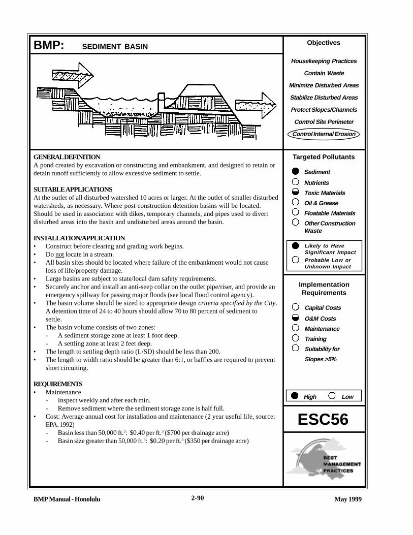
Objectives
Housekeeping Practices
Contain Waste
Minimize Disturbed Areas
Stabilize Disturbed Areas
Protect Slopes/Channels
Control Site Perimeter
Control Internal Erosion
Targeted Pollutants
Sediment
Nutrients
Toxic Materials
Oil & Grease
Floatable Materials
Other ConstructionWaste
Likely to HaveSignificant ImpactProbable Low orUnknown Impact
ImplementationRequirements
Capital Costs
O&M Costs
Maintenance
Training
Suitability for
Slopes >5%
High Low
BMP Manual - Honolulu May 19992-90
ESC56
BMP: SEDIMENT BASIN
GENERAL DEFINITIONA pond created by excavation or constructing and embankment, and designed to retain ordetain runoff sufficiently to allow excessive sediment to settle.
SUITABLE APPLICATIONSAt the outlet of all disturbed watershed 10 acres or larger. At the outlet of smaller disturbedwatersheds, as necessary. Where post construction detention basins will be located.Should be used in association with dikes, temporary channels, and pipes used to divertdisturbed areas into the basin and undisturbed areas around the basin.
INSTALLATION/APPLICATION• Construct before clearing and grading work begins.• Do not locate in a stream.• All basin sites should be located where failure of the embankment would not cause
loss of life/property damage.• Large basins are subject to state/local dam safety requirements.• Securely anchor and install an anti-seep collar on the outlet pipe/riser, and provide an
emergency spillway for passing major floods (see local flood control agency).• The basin volume should be sized to appropriate design criteria specified by the City.
A detention time of 24 to 40 hours should allow 70 to 80 percent of sediment tosettle.
• The basin volume consists of two zones:- A sediment storage zone at least 1 foot deep.- A settling zone at least 2 feet deep.
• The length to settling depth ratio (L/SD) should be less than 200.• The length to width ratio should be greater than 6:1, or baffles are required to prevent
short circuiting.
REQUIREMENTS• Maintenance
- Inspect weekly and after each min.- Remove sediment where the sediment storage zone is half full.
• Cost: Average annual cost for installation and maintenance (2 year useful life, source:EPA. 1992)- Basin less than 50,000 ft.3: $0.40 per ft.3 ($700 per drainage acre)- Basin size greater than 50,000 ft.3: $0.20 per ft.3 ($350 per drainage acre)

May 1999BMP Manual - Honolulu
BMP: SEDIMENT BASIN
2-91
ESC56
LIMITATIONS• The basin should have shallow side slopes (minimum 4:1) or be fenced to prevent drowning.
• Sites with very fine sediments (fine silt and clay) may require longer detention times for effective sediment removal.
• Basins in excess of 25 feet height and/or an impounding capacity of 50 ac. ft. must obtain approval from StateDepartment of Land and Natural Resources.
• Standing water may cause mosquitos or other pests to breed.
• Basins in excess of certain depth and storage volume criteria must meet State Department of Land and NaturalResources and City safety requirements.

May 1999BMP Manual - Honolulu
ADDITIONAL INFORMATION: SEDIMENT BASIN
2-92
ESC56
A sediment basin is a controlled storm water release structure formed by excavation or by constructing an embankment ofcompacted soil across a drainageway, or other suitable location. Its purpose is to collect and store sediment from sitescleared and/or graded during construction or for extended periods of time before reestablishment of permanent vegetationand/or construction of permanent drainage structures. It is intended to trap sediment before it leaves the construction site.The basin is a temporary measure (with a design life of 12 to 18 months) and is to be maintained until the site area ispermanently protected against erosion or a permanent detention basin is constructed.
Sedimentation basins are suitable for nearly all types of construction projects. Whenever possible, construct the sedimen-tation basins before clearing and grading work begins.
Basins should be located at the stormwater outlet from the site, but not in any natural or undisturbed stream. A typicalapplication would include temporary dikes, pipes, and/or channels to divert runoff to the basin inletSome development projects will be required by the City and County of Honolulu to provide a storm water detention basinfor post-construction flood control, desiltation, or stormwater pollution control. A temporary sediment basin maybe con-structed by rough grading the post-construction control basins early in the project.
Sediment basins trap 70-80 percent of the sediment which flows into them if designed according to this handbook. There-fore, they should be used in conjunction with erosion control practices such as temporary seeding, mulching, diversiondikes, etc., to reduce the amount of sediment flowing into the basin.
Installation/Application CriteriaPlanning:To improve the effectiveness of the basin, it should be located to intercept runoff from the largest possible amount ofdisturbed area. The best locations arc generally low areas below disturbed areas. Drainage into the basin can be improvedby the use of diversion dikes and ditches. The basin must not be located in a stream but should be located to trap sediment-laden runoff before it enters the stream. The basin should not be located where its failure would result in the loss of life orinterruption of the use or service of public utilities or roads.
Design:• The sedimentation basin volume consists of two zones:
- The sediment storage zone (at least 1 foot in depth).- A settling zone at least 2 feet in depth.
• The sedimentation basin may be formed by partial excavation and/or by construction of a compacted embankment.It may have one or more inflow points.
• A securely anchored riserpipe with an anti-seep collar is the principal outlet, along with an emergency overflowspillway. A solid riser pipe with two inch diameter dewatering holes located at the top of the sediment storage volumeon opposite sides of the riser pipe usually provides, sufficient detention time for basins draining about 10 acres. Rock,rip-rap, or other suitable outlet protection is provided to reduce erosion at the riser pipe outlet.
• Settling Zone Volume

May 1999BMP Manual - Honolulu
ADDITIONAL INFORMATION: SEDIMENT BASIN
2-93
ESC56
The settling zone volume is determined by the following equation:
(V) = 1.2(SD)Q / VSED
Q = design inflow based on the peak discharge from a specified design storm from the tributary drainagearea as computed using the methods required by the City.
VSED
= the settling velocity of the design soil particle. The design particle chosen is medium silt (0.02 mm).This has a settling velocity (V
SED) of 0.00096 ft/sec. As a general rule it will not be necessary to design
for a particle of size less than 0.02 mm, especially since the surface area requirement increases dramati-cally for smaller particle sizes. For example, a design particle of 0.01 mm requires about three times thesurface area of 0.02 mm. Note also that choosing V
SED of 0.00096 ft/sec equates to a surface area (SA)
of 1250 sq. ft. per cfs of inflow.
SD = settling depth, which should be at least 2 ft., and no shallower than the average distance from theinlet to the outlet of the pond (L) divided by 200 (i.e., SD > L/200).
Total sediment basin volume and dimension are determined as outlined below:
a. The details shown in the attached figure may be useful in designing the sediment basin.b. Determine basin geometry for the sediment storage volume calculated above using a minimum of 1 ft depth and 3:1
side slopes from the bottom of the basin. Note, the basin bottom is level.c. Extend the basin side slopes (at 3:1 max.) as necessary to obtain the sealing zone volume as determined above.d. Adjust the geometry of the basin to effectively combine the settling zone volume and sediment storage volumes
while preserving the depth and side slope criteria.e. Provide an emergency spillway with a crest elevation one foot above the top of the riser pipe.f. The ratio between the basin length and width of the pond should either be greater than 6:1, or baffles should be
installed to prevent short-circuiting.
LimitationsSediment traps and ponds must be installed only within the property limits. Failure of the structure must not result in lossof life, damage to homes or buildings, or interruption of use or service of public roads or utilities. Also, sediment traps andponds are attractive to children and can be very dangerous. Local ordinances regarding health and safety must be adheredto. If fencing of the pond is required, the type of fence and its location shall be shown in the SWPPP and in the constructionspecifications.
• Generally, temporary sedimentation ponds are limited to drainage of 5 acres or more.• Sediment ponds may be capable of trapping smaller sediment particles if additional detention time is provided. How-
ever, they are most effective when used in conjunction with other BMPs, such as seeding or mulching.• Ponds may become an “attractive nuisance” and care must be taken to adhere to all safety practices.• Sediment ponds designed according to this handbook are only practically effective in removing sediment down to
about the medium silt size fraction. Sediment-laden runoff with smaller size fractions (fine silt and clay) will passthrough untreated emphasizing the need to stabilize the soil quickly.

May 1999BMP Manual - Honolulu
ADDITIONAL INFORMATION: SEDIMENT BASIN
2-94
ESC56
REFERENCESA Current Assessment of Urban Best Management Practices: Techniques for Reducing Nonpoint Source Pollution in theCoastal Zones, Metropolitan Washington Council of Governments, March, 1992.
Best Management Practices and Erosion Control Manual for Construction Sites, Flood Control District of MaricopaCounty, Rough Draft - July 1992.
Draft - Sedimentation and Erosion Control, An Inventory of Current Practices, U.S.E.P.A., April, 1990.
Environmental Criteria Manual, City of Austin, Texas.
Guidlines for the Design and Construction of Small Embankment Dams, Division of Safety of Dams, California Depart-ment of Water Resources, March 1986.
Manual of Standards of Erosion and Sediment Control Measures, Association of Bay Area Governments, Jun 1981.
Proposed Guidance Specifying Management Measures for Sources of Nonpoint Pollution in Coastal Water, Work GroupWorking Paper, USEPA, April, 1992.
Stormwater Management Water for the Puget Sound Basin, Washington State Department of Ecology, The TechnicalManual -February 1992, Publication # 91-75.
Water Quality Management Plan for the Lake Tahoe Region, Volume II, Handbook of Management Practices, TahoeRegional Planning Agency - November 1988.

May 1999BMP Manual - Honolulu
ADDITIONAL INFORMATION: SEDIMENT BASIN
2-95
ESC56
TEMPORARY SEDIMENT BASIN
TOP VIEW
STABILIZEDINLET
RISER
INFLOW
EMERGENCYSPILLWAY
OUTFALL
BARREL
SIDE SLOPES3:1 MAX.
EMBANKMENT
EMERGENCYSPILLWAY
5 FT. MAX.
STABILIZEDOUTLET WITHVELOCITYREDUCTIONDEVICEANTI-SEEP
COLLARS
PERFORATED RISER ENCASED INGRAVEL JACKET
RISER WITH HOODAND TRASH ROCK
SEDIMENT STORAGE3 FT. MAX. DEPTH
SETTLING DEPTH2 FT. MIN. DEPTH 2:1
SIDE VIEW