Embed Size (px)
Citation preview
ADVISORY GROUP FOR AEROSPACE RESEARCH & DEVELOPMENT7 RUE ANCELLE 92200 NEUILLY SUR SEINE FRANCE
AGARD LECTURE SERIES 177
Electromagnetic Interference andElectromagnetic Compatibility "-:, . .-
(Interf6rences Electromagn6tiques etCompatibilit6 Electromagndtique)
This material in this publication was assembled to support a Lecture Series under thesponsorship of the Electromagnetic Wave Propagation Panel of AGARD and theConsultant and Exchange Programme of AGARD presented on 10 to 11 June 1991in Kjeller, Norway, 13 to 14 June 1991 in K6nigswinter (near Bonn),Germany, and 17 to 18 June 1991 in Lisbon, Portugal.
S_ North Atlantic Treaty OrganizationOrganisation du Trait de 'Atlantique Nord
91-089499,3,8 "Y.~ \ 'inn""IIIIB, .'- ,,9

BestAvailable
Copy

The Mission of AGARD
According to its Charter, the mission of AGARD is to bring together the leading personalities of the NATO nations in the fieldsof science and technology relating to aerospace for the following purposes:
- Recommending effective ways for the member nations to use their research and development capabilities for thecommon benefit of the NATO community;
- Providing scientific and technical advice and assistance to the Military Committee in the field of aerospace research anddevelopment (with particular regard to its military application);
- Continuously stimulating advances in the aerospace sciences relevant to strengthening the common defence posture;
- Improving the co-operation among member nations in aerospace research and development;
- Exchange of scientific and technical information;
- Providing assistance to member nations for the purpose of increasing their scientific and technical potential;
- Rendering scientific and technical assistance, as requested, to other NATO bodies and to member nations in connectionwith research and development problems in the aerospace field.
The highest authority within AGARD is the National Delegates Board consisting of officially appointed senior representativesfrom each member nation. The mission of AGARD is carried out through the Panels which are composed of experts appointedby the National Delegates, the Consultant and Exchange Programme and the Aerospace Applications Studies Programme. Theresults of AGARD work are reported to the member nations and the NATO Authorities through the AGARD series ofpublications of which this is one.
Participation in AGARD activities is by invitation only and is normally limited to citizens of the NATO nations.
The content of this publication has been reproduceddirectly from material supplied by AGARD or the authors.
Published June 1991
Copyright O AGARD 1991All Rghts Reserved
ISBN 92-835-0620-0
Prim,,d by Specialsed Prining Services Limited40 ChMgowfl Lane, Loighton, Essex IGIO 3TZ

Abstract
Two aspects of the current electromagnetic (EM) environment having great significance for NATO systems are:
(a) electromagnetic interference (EMT) arising from both natural and man-made sources;
(b) electromagnetic compatibility (EMC), i.e. the ability of an EM system to function as specified without being susceptible toEM!, and without itself generating excessive EMI which would cause other systems to malfunction.
The Lecture Series will first set EMC in a NATO operational context. Major EMI generation mechanisms will then be reviewedand their characteristics outlined.MTe manner in which EMI energy couples into EM systems will be discussed, together withthe analysis and modelling tools available to assist in computing such interactions.
Modern EMC testing methods and environments will then be examined and their limitations indicated. The relationshipbetween NATO and civilian EMC requirements will be examined in the light of the European Community EMC Directive.Consideration will also be given to the problems of spectrum management and conservation as they affect systems intentionallyradiating EM energy, eg. radio, radar, etc.-
Finally, design principles and techniques for EM systems with effective EMC characteristics will be presented. A Round TableDiscussion will enable attendees to interact in some detail with the lecturing team.
This Lecture Series, sponsored by the Electromagnetic Wave Propagation Panel of AGARD, has been implemented by theConsultant and Exchange Programme.
Abre g e
Les deux aspects du milieu electromagnetique (EM) actuel qua revitent une importance particulire pour les systimes mis enoeuvre par les pays membres de I'OTAN sont:(a) Lea interferences ilectromagnetiques (EM!) creees aussi bien par des elements naturels qu'artiflciels.
(b) La compatibiliti electromagnetiqe (EMC), qui est l'aptitude d'un systeme EM h tenir les sp~cifications sans Etresensible 17-M! et sans ginerer lui-mime des perturbations EM! excessives qui perturberaient fortement d'autressystimes.
Le cycle de conferences situera d'abord 17EMC dens son contexte operationnel au sein de I'OTAN. Les principaux mecanismesginirateurs d EMl seront ensuite itudies et leurs caracteristiques indiquies. La maniere dont l'energie EMI est couplee auxsysticies EM sera diacutie, sinsi que lea moyens d'anaiyse et de modilisation proposes pour le calcul de telles interactions.
Les mdthodes et lea environmements d'emsi EMC modernes seront passes en revue, avec indication de leurs limitations. Lerapport qi existe entre lea besoins de I'OTAN et ceux de lindustiie civile en mati~re dTEMC sera examine hala lwnikre de ladirective de Is communaute europ6enne sur I7EMC. II sera tenu compte 6galement des probilses de la gestion et de lar nmPrvation do spect dans [a mesure oO ils out une incidence sur lea systawnes qui ont pour fonction li'mission derayomemenw- EM, h smvr lea systasnes radar, radio etc..
Enfi% les peicpes et lte nqe quim pennttet I rilization de systinmes EM Jotas de caracteiatiques EMC effectivesmeon i eaes. Use table ronde oipnis&e en fin de s6ance permettra aux participants de discuter des points perticuliers
Ce cycle de costfimwceat prisenti dana It cadre du programme des Consultants et des Echanges, sous l'eide du PanelAGARD sir Is Propagation des Ondes ElcrUnagm ti11 s
- VOCIn
co &Wiii

List of Authors/Speakers
Lecture Series Director: Prof. M. DarnellDepartment of Electronic EngineeringUniversity of HullHull HU6 7RXUnited Kingdom
AUTHORS/SPEAKERS
Prof. Ir J. Catrysse Prof. S. KubinaKatholieke Industriele Hogeschool EMC LaboratoryWest Vlaanderen Concordia UniversityZeedijk 101 Loyola CampusB-8400 Oostende 7141 Sherebrooke Street WBelgium Montreal H4B I R6
QuebecDr TK. FitzSimons Canada(former Head EMC Section, ARFA, NATO Hqs)Route Tout Vent Dr A.C. MarvinSainte Foy des Vignes Dept of Electronics24100 Bergerac University of YorkFrance Heslington
York YOI 5DDDr G.H. Hagn United KingdomSRI International1611 N Kent Street Prof. C.R. PaulArlington, VA 22209 College of EngineeringUnited States Department of Electrical Engineering
University of KentuckyLexingtonKentucky 40506-0046United States
iv
Contents
List of AuthorsSpeakiers iv
ReferenceIntroduction and Overview Iby Prof. M. Darnell
Natural and Man-Made Noise and Interference: Mechanisms and Characteristics I(Outline Only)
by Dr G.H. Hagn
Propagation and Coupling Mechanisms 2by Dr A.C. Marvin
Numerical Analysis and Modelling Techniques 3by Prof. S. Kubina
Cables and Crosstalk 4by Prof. CAL. Paul
Grounding, Shielding and Bonding 5by Prof. Ir J. Catrysse
A Review of the NATO EMC Analysis Programme and Related European 6Community Developments
by Dr T.FitzSimons
Spectrum Management and Conservation 7by Prof. M. Darnell
Measurement Environments and Testing 8by Dr A.C. Marvin
Design Principles for Effective EMC 9by Prof. IT J. Catrysse

INTRODUCTION & OVERVIEW:ELECTROMAGNEnC MERFERENCE & ELECTROMAGNETIC COMPATMILY
M DarnellHull - Warwick Communications Research Group
Department of Electronic EagineeringUniversity of Hull
Hull HU6 7RXUK
Electromagnetic interference (EMI) and electromagnetic which is likely to escalate as the specifications of civiliancompatibility (EMC) are topics which have been of concern to systems improve. Also, a prolonged period of reduced interna-the military community for many years. and especially during tional tension in the NATO theatre of operations is likely tothepast half century when electrical aid electronic equipments lead to proportionately lower military budgets and expenditurehave proliferate& The ability of NATO forces to operate as on military EM systems. Thus, there will be an increasedplumed over the complete range of operational scenarios is economic impetus in favour of civilian programmes. Again, itcriticallydependenton the correct functioning ofa wide variety becomes probable, therefore, that military system designersof electromagnetic (EM) systems, both individually and col- will have to make greater use of, and adapt, primarily civilianlectively; therefore, any foreseeable interactions and perform- EM equipments and systems to meet their requirements. Thus,ance degradation of such EM systems must be minimised - military EMC planners and designers must be aware of relatedpreferably by effective design. civilian developments.
Excessivegeneratonoforsusceptibility to, EMnoise and One specific area in which the requirements of militaryinterference, resulting in inadequate EMC, is one potential and civilian systems are, to some extent, in conflict is in radiosource of interaction and performance degradation which may spectrum allocation. Increased numbers of civilian radio sys-result in reduced operational effectiveness. For this reason, the tems and services are creating a situation in which civilianimportance of achieving EMC has been stressed within NATO bands are becoming progessively more congested and there isfor at least the last two decades; bodies such as the EMC Sec- pressure to release bands in the spectrum which are currentlytion within NATO and the NATO EMC Advisory Group have largely assigned to military users. Also, the general level ofbeen responsible for a continuing appraisal and analysis of manmade radio noise in all bands,due to a proliferation of EMactual and predicted EMC problems, leading to recommenda- systems, can be expected to become greater with time. Ations for action and specific projects. Within AGARD, the combination of reducedspectrum availability and higher noiseElectromagnetic wave Propagation Panel (EPP) and Avionics levels inevitably puts an increased emphasis on the EMCPanel (AVP) have also continued to promote scientific analy- aspects of radio-based systems, in both military and civiliansis and discussion of EM! and EMC problems, eg (AGARD, contexts.1974) and (AGARD, 1987).
EMC is a term which can mean "all things to all men". andIn general, it can be stated that the military EM environ- so it ir appropriate here to provide a formal definition which
ment is reasonably well defined in terms, say, of maximum will apply in this Lecture Series. There are two aspects to thethreat levels; hence, it has also been possible to quantify EMC definition (Darnell, 1988), ie EMC describesrequirements with adegree of precision. In the civilian domain,however, an informed appreciation of the significance of EM! (a) the extent to which a given EM system can functionand EMC has been slower in developing, probably because, acording to its design specification without generating EM atuntil relatively recently, that environment had a much lower a level which would cause other specified EM systems toaverage density and variety of EM systems than the typical malfunction - the "emission" aspect;military situation. Over the past decade, the civilian environ-ment has become increasingly "rich" in sources of EM! and (b) the extent to which a given EM system can functionhence achieving EMC has now become a significant concern, according to its design specification in a defined EMI environ-Increased awreness of the likely implications of the installs- ment without itself malfunctioning - the "immunity" aspect.tionofavastrangeof EM equipments and systems, unspecifiedfrom an EMC viewpointhas led to m increasinglyc omprehen- It is seen, therefore, that EMC is "bi-directional" in that it
* sive range of specifications aid standards, culminating in die is concerned both with EM energy emitted by a system andformulation md ratification of di EMC Directive by die energy absorbed by a system. Esentially, therefore, EMCEuropem Comnmmity (BC Council Directive, 1989), by which specifications and standards are concerned with the control ofviruially all EM equipments aid systems manufactured mid the "interface" between an equipment/system and its EMsold in the BC will be subject to legal EMC requirements with environent; FS. 1 shows this interface diagramatically. Oneffect forn 1992. either side of the interface illustated in Fig. 1, are listed a
number of factors and trends which at tndmg to make dieAnt bmwi number of EM sysam continue to be attainment of EMC a more difficult task as time progresses.
delayd fermilisay purposes these now have to take accountnot a* of o military s m, but also of the parallel As an introduction to the detailed specialist lectures thatincrun in vfn s ms It addition, it is beoMins more follow, a brief overview of the objectives and content of
sub-sysm &mi eeoped pIsnu forraiily for Series No. 177 will now be given.prpmoss, lobe inhcrporated into militery installaden, atrend

1-2
Tie first two lecture ame of a fundmnental nature and will ing Round Table session will provide an opportunity forprovide eana intoductory backgrond material. Initially, paticipants to discuss with the lecturing team any, possiblythe lecture onNatural and man-made noise and interference: more detailed, points arising from the individual lectures, andmechanisms and characteristics" will survey naturally-occur- to examine general principles in greater depth.ring and man-made noise and interference sources which havedie potential to degrade the performace of NATO EM equip- REFERENCESmams and systems of various types. The source mechanismswill be described, together with their spectral "signatures" in I. AGARD (1974): "Electromagnetic noise, interferencethe various bends of the radio spectrum. Analysis models for andcompatibility". Joint AVP/EPPSymposium, AGARD-CP-the effects of internal and external sources of EMI on EM 159, Paris.system performance will also be presented. This will then befollowed by a lecture an "Propagation and coupling mecha- 2. AGARD(1987): "Effects of electromagnetic noise andnisms" which willprovideadescription of the physical basis of interference on performance of military radio communicationEM theory required to appreciate the coupling phenomena systems", EPP Specialists' Meeting. AGARD-CP-420, Lisbon.which can give rise to a lack of EMC.
3. CouncilDirective(3rdMay 1989): "On the approxima-In order to be able to treat EMI and EMC problems in a tion of the laws of the Member States relating to electr mag-
quantitative nmer, it is necessary to be able to apply system- netic compatibility", published in the Official Journal of theatic analysis and modelling procedures. The lecture entitled European Communities, No. L 139/19 - 26, dated 23rd May"Numerical analysis and modelling techniques" will describe 1989.a range of such techniques which can potentially be applied tothe EMC analysis of various types of coupling configurations. 4. Darnell, M. (1988): "Electromagnetic compatibility",A companion lecture entitled "Cables and crosstalk" will Manual for Short Course for Engineers and Managers, Yorkdiscuss the analysis models applicable to the prediction of Electronics Centre, University of York, UK.coupling effects between circuits in close proximity, anddifferent conductors in cables, via inadvertent energy transfermechanisms.
The first day of the Lecture Series will conclude with alectur on "Shielding. grounding and bonding". Here, theprinciples, pracce and implications of these three basic topics,of vital importance in achieving EMC, will be outlined.
Day 2 of the Lecure Series will commence with a lectureentitled "A review of the NATO EMC analysis programme andrelated civilian developments". This will describe in somedetail specific activities associated with the NATO EMCanalysis programme, particularly in relation to frequencyassignment and planning; in this context, the interaction ofmilitary and civilian interests will be discussed.
The following lecture on "Spectum management andconservation" will review the propagation mechanisms avail-able to radio systems in the various bands of the radio fre-quency (RF) spectrum. The way in which frequency planningprocedures are illuenced by these mechanisms and equipmentcharaceiic and imperfections will be considered, togetherwith spectrumn control procedures.
Attention will then be turned to common methods ofassessing EMC characteristics of EM systems in a lecture on"Measuremazzenvironments and testing".The various test en-vronments available will be described; their rationale, limita-dio and precision will also be examined.
The final lecture on "Desin principles for effectiveEMC" will takeasysisms level approach to achieving adequatelevels of EMC; the basic characteristics of systems affectingtheir EW pafsmmice will be reviewed, and a number ofdesig nds pasdtled. A general approach to tackling EMCprin m will be suggesedmi
I is obvls that in two days only brmd principles andmooMepCms be pu d bythelecr. Acanchid-

1-3
EQIE-O TASTiEM E M ENVERONMENT
MORE EM SYSTEMS CAPABLE OF GREATER NUMBERS ANDBEING AFFECTED BY EMI DIVERSITY OF EMI SOURCES
LOWER-POWER LOGIC FASTER CLOCK RATESFAMILIES. MORE SUSCEPTIBLE SPREADING EMI ENERGY TOTO EMI HIGHER FREQUENCIES
NON-METALLIC PACKAGING MORE MOBILE SOURCES OFGIVING POORER ISOLATION EMI
INCREASED NUMBERS OF MORE ENVIRONMENTALLARGE, DISTRIBUTED EM COMPLEXITY, EG ELECTRICALINSTALLATIONS NON -LINEARITIES
NON-EMC-ORIENTED DESIGN INCREASE IN EM EMISSIONSPROCEDURES USED FOR THE WITH TIME DUE TO AGING OFMOST PART EQUIPMENT
(CONTROLLED BY EMI/EMCSPECIFICATIONS & STANDARDS)
Fig. 1: EMC as an interface control problem
V

'I.
NATURAL AND MAN-MADE NOISE AND INTERFERENCE:MECHANISMS AND CHARACTERISTICS
(Outine Only)
by
G.H.HagnInformation and Telecommunications Sciences Center
SRI International1611 N. Kent Street
Arlington, VA 22209United States
I. Overview Lecture
2. Definitions of Noise and Interference
3. Sources of Radio Noise
3.1 Categories of Sources
3.2 Examples of Source Characteristics
4. System Noise Figure and Noise Factor
5. Worldwide Minimum Noise Levels
6. Empirical Noise Models
6.1 Natural Noise from Lightning
6.2 Man-Made Noise
6.3 Analytical Noise Models
7. Effects of Noise on Systems Performance
8. Channel Occupancy and Congestion
8.1 Definitions of Occupancy and Congestion
8.2 Examples of Occupancy and Congestion
8.3 Modeling of Congestion
9. Noise Measurements and Standards
9.1 Field Strength Measurements
9.2 Noise Detectors
9.3 Standards (IEEE, SAE, CISPR)
10. Future Noise Trends
i j
1-2
NATURAL AND MAN-MADE NOISE AND INTERFERENCE:MECHANISMS AND CHARACTERISTICS
by
G.H. Hagn
ABSTRACT
The objective of the lecture is to define noise (a cause) and-interference (an effect) and describe some of the sources of bothnatural and man-made radio noise and interference which have the potential to degrade the performance of radio and otherelectromagnetic systems of interest to NATO. The following types of sources will be included: natural noise (e.g., from lightning,the sun and the cosmos), and man-made noise (e.g., from external sources such as powerlines and ignition systems and fromsources internal to a receiving system associated with electronic devices and components). The source mechanisms will bediscussed as well as the characteristics of the sources and their "signatures" in the bands from ELF through SHE CCIRestimates of worldwide minimum effective antenna noise figures versus frequency and empirical noise models (for noise ofnatural and man-made origin) will be presented and discussed. Modeling the composite noise environment generated bymultiple types of sources will be discussed. The analytical noise models of Hall and Middleton will be described. The propercombining (in a model of overall system noise figure) of the predictions of models for individual external and internal noisesources will be discussed. The effect of noise on analog voice and on digital communications systems will be discussed. HFchannel occupancy and band congestion will be defined, and the measurement and modeling of congestion will be discussed.Noise measurements and standards will be reviewed, and future noise trends will be discussed.

42-1
Propagation and Coupling Mechanisms.
Dr A.C. MarvinSenior Lecturer, Department of Electronics.
University of York, York YOI 5DD.United Kingdom.
Summary. useful, and these I recommend to students and
This lecture aims to cover the backgiound those who need a refresher course. They are the
electromagnetic theory needed to understand the books by Christopoulos [1] and Liao [2].
phenomena that lead to EMC problems, thetechniques used to alleviate the problems and 1) Field Concepts and Basic
the measurement techniques used to assess the Electromagnetics.problems. In dealing with electromagnetic
The lecture starts with a discussion of the interference and electromagnetic compatibilityconcepts associated with vector and scalar fields, we are concerned with the generation,and then review Maxwell's Equations and their propagation and measurement of electric andsolution in the form of electromagnetic waves. magnetic fields. It is useful, therefore, at theThe structure and properties of electromagnetic outset to review the concepts associated with thewaves are reviewed, physical phenomena described as fields.
Concepts associated with inductive and Definition; If a physical phenomenon exists andradiative coupling between circuits will be can be measured over a volume of space, thendiscussed, and the boundary between the two the phenomenon can be described as a field.coupling types is explored in terms of the Graphical or other visual representations of theseparation of the coupled circuits as a fraction of magnitude of the field are described as field
the wavelength, plots.
In view of the limited time available to One of the most common field plots incover this revision material, the approach during everyday use is a weather map. The isobars onthe lecture will be intuitive. The lecture notes the map are a contour plot of the atmosphericcontain a more rigourous mathematical pressure at sea-level over part of the earth's
treatment, surface - a two dimensional pressure field plot.Atmospheric pressure has a magnitude but no
Introduction. direction associated with it. The air can exert apressure in any direction. The pressure field is
In order to understand the causes and thus a scalar field.
solutions of Electromagnetic Compatibilityproblems it is necessary for the engineer to have The isobars on the weather map are also an
a working knowledge of electromagnetics. This indication of the atmospheric wind direction at
subject is traditionally unpopular with heights around 500m above the ground. As such,
engineering students as many of the concepts they are also a plot of the wind velocity field. Asinvolved seem to be abstract, and the this field has both magnitude and direction, it is amathematical formulations required to make the vector field.analysis tractable are often unfamiliar, not beingseen in other branches of electrical engineering. In electromagnetics we are concerned with
Unfortunately, there are no short cuts to a proper both scalar and vector fields.understanding of the subject, however, much canbe gained by an appreciation and application of If a scalar field is differentiated with
the important results of electromagnetic theory. respect to position, the result is a vector field. For
In this lecture I have attempted to distil the example, if the height information of land on a
important results and concepts concerning map is regarded as a plot of a scalar field, then
electromagnetic waves and to use them to the result of differentiation is the gradient of the
describe the propagation and coupling of waves land which has a direction associated with it - e.g.in and around a system. The lecture attempts to the land slopes to the north.lay a foundation for others on more specifictopics of concern in the study of ElectromagneticCompatibility. For a more detailed treatment thereader should consult one of the many books onthe subject. Two I have found to be readable and

2-2
Electric Fields. point, and can be evaluated as the integral of theforce experienced along the route by the test
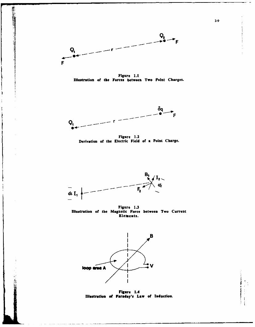
The concept of an electric field arises out of charge. Work is a scalar quantity, and hence aCoulomb's Law describing the observed vector scalar work field can be plotted in the spaceforce F* experienced by two point charges Q1 Q2 around the charge system. This scalar field isseparated by a distance r as shown in Fig 1.1. termed the electric potential field and is the
amount of work required to move one Coulomb ofF = (QIQ 2/4xer 2 ).a12 Newtons charge from the reference point to a given
position in space. The natural units of electricThe term e is the permittivity of the medium potential are Joules/Coulomb. By definition;surrounding the charges and is one of theelectrical parameters of the medium. The term lJoule/Coulomb iVolta12 is a unit vector in the direction of a straightlinejoiingthe hares.In elementary text books the referenceline joining the charges. point used to define the potential of a point
(*Bold characters are used to denote vector charge is at infinity where the electric force fieldquantities is used throughout this paper) is zero. This gives a potential value V at a
distance r from a point charge Q of;If one of the charges, say Q2 is replaced by
a vanishingly small test charge 8q as shown in Fig V = Q/4xer Volts1.2, which does not perturb the charge Qi then anelectric force field E due to the charge Q, can be As the potential V is proportional to thedefined as; charge Q, the principal of superposition applies,
and the potential at a point due to a chargeF = 8qE Newtons distribution can be evaluated by scalar
summation of the potentials of the point chargesand therefore comprising the distribution.E = Ql/xer2 ).ar Newtons/Coulomb As the scalar electric potential field was
evaluated by integration along a path through the
The unit vector is in a radial direction from the vector electric force field, differentiation of the
charge Qi towards the test charge. electric potential field V with respect to positionThe electric force field can be measured at any yields the electric force field.
point around Q, by measuring the force exertedon the test charge. It is a vector field, having E = - grad Vboth magnitude and direction and has the unitsNewtons/Coulomb. As the electric force field E is The units of the electric force field can thus beproportional to the magnitude of its source Q1, re-defined in terms of those of potential.the system is linear and the principle ofsuperposition applies. The total electric force field lNewtonlCoulomb = lVolt/mat any point can be obtained by vectorsummation of all the contributions from all the where the gradient operator is used tocharges in a system. differentiate the potential field with respect to
position.A further vector field quantity D the
electric flux density is defined as; Conduction and Displacement Current.
D = eE Coulombs/m 2 A material with mobile charge is called aconductor. If an electric field is applied to such a
or alternatively material the charge moves under the influence ofthe field and a conduction current flows. In most
D = Q1/4xr 2 .aCoulombs/m 2 materials which are homogeneous and linear, therelationship between the applied electric field E,
The electric flux density is independent of the the conductivity a (Siemens/i) and the resultant
medium surrounding the source charge. conduction current density Jc is given by Ohm'sLaw.
Electric Potential. c = aE Amps/m 2
In moving the test charge around in an The time derivative of the electric flux densityelectric force field an amount of work is dD/dt also has the units Amps/m 2 .This is calledperformed. The amount of work required to the displacement current density JD.move a test charge from some reference point toany point in the space surrounding the charge In a general material with an appliedsystem is independent of the route taken to that electric field E the total current density J is.

2-3
J = Jc + JD = ci.E + e.dE/dt This is illustrated in Fig 1.4. Faraday's law is thebasis of the operation of transformers and many
For sinusoidal time variation at angular other devices. It is also the cause of manyfrequency w this becomes spurious coupling problems in and around
J = (r + jwe)E electronic circuits.
Note that the displacement current is in time Statement of the EMI/EMC Problem.phase quadrature with the conduction current. The concepts described above should beThe classification of materials into dielectrics or familiar to any electrical/electronic engineeringconductors depends on the ratio of the conduction student. For the purposes of this lecture series wecurrent to the displacement current. can state them as follows:
Magnetic Fields.
A parallel set of arguments can be used toshow the existence of magnetic fields associatedwith the forces observed between conductorscarrying electric currents. The magnetic field Hhas units Amps/m. The force field associatedwith magnetic phenomena is the magnetic fluxdensity B;
B = }H Tesla A system of moving charges givesrise to a set of time varying electric and
Fig 1.3 shows the two short current carrying magnetic fields. These fields will interactconductors or current elements each of length dl. with other distant mobile charge givingThe force F2experienced by conductor 2 is given rise to electric currents. If the interactionby the vector product; is intentional we call it a radio system, if
not it's EMI.F2 = 12d x BI
2) Maxwell's Equations andwhere for direct currents Bi, the magnetic flux Electromagnetic Waves.density set up by conductor 1, is given by theBiot-Savart Law. The term ju is the permeability The concepts described in section 1 areof the surrounding medium the material constant described fully by Maxwell's equations listed inassociated with magnetic phenomena. vector differential form below.
Bi = t.lidl x rrz/4Xr 2 curiE = -dB/dt
The vector lid] represents the magnitude and curtH = J + dD/dtdirection of the short current element, theconvention being that the vector direction is that dive = p/eof the current flow. divH = 0Faraday's Law of ElectromagneticInduction. Here Jc is the conduction current density
(Amps/m 2), and p is the charge densityIf a loop of wire of area A has a uniform (Coulomb/m 3 ). These two terms jointly
magnetic flux density B passing through it, the represent the moving charges referred to intotal magnetic flux cutting the loop is V where; section 1 as the sources of the electric and
magnetic fields. The four differential equations0 IBI.A.CosO Webers. can be solved to yield coupled wave equations
for the electric and magnetic fields - i.e. ane is the angle between a line along the flux vector electromagnetic wave. Examination of Maxwell'sdietion ande ten axi of e lon.If the maugcr equations shows that both field components mustdirection and the axis of the loop. If the magnetic be present in the time varying case. If electricflux changes, a voltage V is induced around the fields originate from electric charges, then aloop; change in an electric field requires charge to
move - an electric current, the source of aV-d@I/dt Volts.magnetic field, must therefore occur.
The conventional form of the solutionassumes that the fields occupy a region of space

2-4
well away from the field sources where both p For free space the velocity is 3 x 10⁸ m/sec. Forand J© are zero. The solution can then be most dielectric media, the permeability is that ofconfigured in the form of a spherical wave free space and the intrinsic impedance andpropagating away from a source region of velocity are reduced by a factor equal to thenegligible dimensions as shown in Fig 2.1. In square root of the relative permittivity (dielectricspherical co-ordinates, with the source at the constant) of the medium (e = eoer).origin and sinusoidal excitation, the fieldequations are; If the wave propagates into a conducting
medium, conduction currents are present as wellEA = Eo exp(jmt).exp(-j1r)/r ae V/m as displacement currents. The behaviour of the
wave in the medium depends on the ratio ofHt = Hoexp(joft).exp(-j1r)/r. at Aim conduction current to displacement current. In
media that are poor conductors, for example mostpractical dielectrics, the conduction current is
Here w is the angular frequency and J3 is the small (a << e), and the properties of the wave arephase constant defined as; those of a perfect dielectric of the same
permittivity with the addition of a smallP = 2x/), attenuation term. The wave equations become;
where X is the wavelength and r is the distance E0 = Eo exp(jmt).exp(-j1r).exp(-ar)/r ae V/mfrom the source. The two exponential termsdescribe the temporal and spatial oscillatory Ht = Hoexp(jwt).exp(-j[r).exp(-ar)/r. at A/mbehaviour associated with a sinusoidal wave. Thefields decay at a rate inversely proportional to where ot is the attenuation due to powerthe distance from the source. The power flux dissipation given by;density of the wave is given by the PoyntingVector P a = (o/2)(ijE) t / 2
P = 1/2(ExH*) Watts/M2 In the case of a good conductor such as a metal (a* denotes e we) the solution of Maxwell's equations results
where the asterisk d the complex in a wave that is heavily attenuated with theconjugate. The power flux density decays at a wave impedance and velocity both substantiallyrate inversely proportional to the square of the reduced. The phase constant and the attenuationdistance from the source as the energy factor are numerically equal and given by;propagated by the wave spreads out. As thefields are orthogonal to the radial direction and to a = 13 (xfi'a)1 / 2
each other, the vector product of the fields givesa power flow in the radial direction. where f is the frequency. The situation is
illustrated in Fig 2.2 where it can be seen that the
The ratio of the electric field to the wave fields are attenuated to insignificant
magnetic field is determined by the electrical values in less than a wavelength. As the wave is
parameters of the medium in which the wave is propagating in a good conductor with
propagating. For a dielectric medium these are predominantly conduction current, the field
the permittivity e and the permeability vs, and amplitude is proportional to the conductioncurrent in the conductor. As the current decays
E/H = Z = (js/e)'/ 2 rapidly with depth of penetration, a waveentering a conductor from another medium is
Z is the intrinsic impedance of the medium. For confined to a surface layer of current. The depth
free space (vacuum, eo, to) the intrinsic of penetration of the surface layer is determined
impedance is 3770. The wave impedance can be by the attenuation, and the skin depth 8 isused to give other expressions for the power flux defined as that depth by which the wave hasdensity; decayed to l/e (0.37) of its surface value.
P = E2/Zar = H2 .Zar W/m 2 =
The velocity v of the wave is also determined bythe parameters of the medium, and solution of The velocity is given by mB, and the wave .Maxwell's equations shows it to be given by; impedance is complex and equal to (I + j)/ob.
v = i/Qt £)' m/sec. For example if copper (a = 5.8 x 10⁷S/m, ji = 4n x10 7 HWm) is considered at a frequency of IMHz,the following results are obtained;

2-5
skin depth = 66pm curl(grad V) = 0
wave velocity = 414m/sec can be used to set the Lorentz gauge condition forelectromagnetic radiation;
wave impedance = (l + j) x 2.6 x 10-40 EB + dA/dt = -gradV
Compare these with a velocity of 3 xlOmlsec
and impedance of 3770 for free space. In the static case (d/dt = 0 ) we get therelationship used to define electric potential in
3) The Radiation Mechanism. section 1. In the time varying case where thecharge distribution is changing by means of
The preceding section did not specify the conduction currents the electric field is sourcedsource of the electromagnetic wave other than to by both the scalar electric potential V (derived
state that a set of time varying charges are from the charge distribution) and the vector
required. The wave description is also for a magnetic potential A (derived from the
region well away from the wave source. In the conduction current distribution). Thus from any
region close to the wave source, the wave current distribution, representing any electronic
properties are modified by the proximity of the equipment, the electric and magnetic fields can
source, and the nature of coupling between be evaluated. It is often computationaly more
circuits is determined by the distance between convenient to evaluate the vector magnetic
the circuits. Clearly, if the coupling is to be potential for a current distribution, thereby
understood, the structure of the fields close to a enabling the magnetic field to be evaluated. The
radiation source must be studied. electric field can then be found by application ofthe appropriate Maxwell equation.
In section 1 it was stated that the sourcesof electric and magnetic fields are electric charge In order to illustrate the complexity of thep and conduction current density Jc (moving field structure close to a radiating source, the two
chande) co cto cure aelemental source types will be considered. Thecharge). These two sources are related by the first is the elemental electric dipole or currentcontinuity of current relationship, element as shown in Fig 3.1. This comprises an
isolated current filament of negligible assumeddivJc = -dpi/dt diameter and length dl which is small compared
is to the wavelength of the radiation and also to theAs the divergence of the magnetic flux density i distance from the dipole to the observer at P.zero, a standard vector identity ( div.(curlA) = 0 The current is I and is assumed to be sinusoidally) can be used to define the vector magnetic varying with angular frequency €o. Evaluation ofpotential A such that: the vector magnetic potential at P and thus the
B = curiA fields gives the following result. In spherical co-ordinates, the magnetic field has only a *component while the electric field has both radial
For direct currents the vector magnetic potential and 0 directed components. Z is the intrinsicof a current element Idl can be derived from the impedance of the medium surrounding theBiot-Savart Law dipole.
A = P.Idl/4xr H*= (I dl / 4x). (1/r 2 -jP/r)
where r is the distance from the current element p(j - jo) Sine . a*
to the observer. Eq = (I dl / 4x). (jOp/r + Z/r2 + lfjo0er 3)
For ocillatng fields at some distance from exp(j)t - jpr) . Sine . ae
the source retarded potentials must be used toaccount for the finite propagation time of field Er = (I dl / 4x) . (2Zft 2 + 2/jwr 3)
variations. These are of the form; expojot - jpr). Cose . ar
V = (Q/4ter).exp(jet - Pr) The second elemental source type is theelemental magnetic dipole or current loop as
A = (j&.Idl/4xr).exp(jwt - Pr) shown in FiX 3.2. In this case the loop of area Aha dimensions small compared to the distance
The vector magnetic potential can be substituted to the observer and the wavelength. The currentinto the Maxwell eqution for the curl of E to loop has a magnetic field with radial and 9give; components and an # directed electric field.
curl(E + dAd ) 0 Z# = (I A /4x). (Zpr 2 -Z 2 /r)
Again a standard vector identity exp(Jst-jpr). SlnO.

2-6
He = -(I A / 4s) . (P2/r - jP/r 2 - l1r 3) In the radiation field iegion the two sourceexp(j t - jor) . Sine. a types are indistinguishable. There are no radial
fields, and the ratio of the electric to magnetic
Hr = (I A /4) . (j/r2 -jr3) fields is the intrinsic impedance of theexp(jwt - jlr). Coe . ar surrounding medium. The two source types differsignificantly in the induction field region where
For either source, the field equations can be 1/ < Ir 1 , Ir 3. The differences can be bestdivided into four sections. Ile first Is a source illustrated by examining the transverse wave
term indicating that the radiated fields are impedances ZT, defined as the ratio of the 0 and
proportional to the dipole size and current. This directed field components for 0 equal to z/2, for
term is often refered to as the dipole moment. both source types. For the electric and magneticThe second is a term describing the amplitude dipoles respectively we have;decay of the fields as a function of distance r. It isthis term that is of most interest. The third is a ZTo = lljcOergeneral wave description of the fields, and thefourth is the directional properties of the fields. ZTm = jcair
Returning to the second term in the In each case the impedance is reactive andequations, it can be seen that the fields decay as dependent on both distance and frequency.inverse functions of the first three powers or the Manipulation of the relationship between co and X,distance. At large distances from the source, the the wavelength, gives the transverse waveonly significant term is the inverse distance term impedances in normalised wavelength terms;resulting in a wave of the type described insection 2. For either type of source, the inverse ZTe = -j(Z/2x)/(r/X)distance term is only present in the 8 anddirected components both of which are ZTm = j(2xZ).(r/X)orthogonal to the radial direction of propagation.These field components transverse to the radial The magnitudes of these impedances are plotteddirection of propagation are refered to as the in Fig 3.3 for all values of (r/X). Very close to theradiation fields of the sources. The radial field in Fig 3.3cfr lpvles r else hecomonetshave only second and third order source the electric dipole has a relatively highcomponents htransverse wave impedance indicating that theinverse distance terms and are thus insignificant electric field is dominant. The magnetic dipoleaway from the source. Note also the CosO has a very low transverse wave impedancedirectional properties of the radial fields as indicating that the magnetic field is dominant.opposed to the SinO directional properties of thetransverse fields. Very close to the sources the 4) Radiation from Circuits and Equipment.inverse cube and inverse square terms aredominant. These are known as the induction An electronic device comprises a largefields. The boundary between the dominant number of circuits, each of which may beradiation fields at large distances from the carrying a time varying current and thussources and the dominant induction fields close to emitting radiation. At typical clock frequencies ofthe sources is not distinct. A guide can be 10MHz to 50MHz significant harmonics areobtained by equating the magnitudes of the present to at least 1GHz, a wavelength range ofradiation field and induction field terms. If the 30m to 300mm. As individual tracks and loops onmagnetic field of the electric dipole is used then; circuit cards have dimensions in the range 10mm
to 100mm, they can be considered as elemental
I/r 2 = /r radiators over most of that frequency range.Examination of the equations for the radiation
and from electric and magnetic dipoles indicates thatthe magnitudes of the radiation fields are
r = l/l = 12x proportional to the frequency and the square ofthe frequency respectively. Thus a circuit
Thus at distances less than about one sixth of a carrying a digital signal with the time waveform
wavelength the induction field terms are and frequency power spectrum shown in Fig 4.1dominant, ad at greater distances the radiation will radiate a spectrum modified by the
field terms dominate. At distances greater than frequency response of the radiation mechanismabout one wnvehlpau, the only significant terms as shown in Fig 4.2. The highest radiated fields
am the rad eW Bx anaton of the field are associated with spectral energy atequations Is the udima. ifid region shows that frequencies beyond those normally consideredthey ae IMticald to the sherical wave solutions important for the operation of the circuit. Withto Maxwell's equations given in section 2 with the clock frequencies in the 10MHz to 50MHz region,addition of a term espessisg do directional the radiated energy is predominantly in theproperties of the dipole. V-F/U.F frequency range.
Jv

2-7
A typical circuit which is small compared to its own current. As the current on one elementthe wavelength under consideration may radiates a set of fields that impinge on all thecomprise both types of elemental source. other elements, this mutual coupling between theConsider the circuit shown in Fig4.3. If it is elements must be accounted for when evaluatingregarded as an isolated circuit on a circuit card, the currents on the equipment. There exist athe circuit diagram is representative of both the number of numerical methods which enable suchelectrical equivalent circuit and its physical solutions. The most useful one is the method oflayout. Electric currents that circulate around the moments developed by Harrington , the computercircuit loop clearly give rise to magnetic dipole code Numerical Electromagnetics Code (NEC)radiation. The presence of the circuit tracks on being the most common implementation of thisthe card means that parasitic capacitance exists method. These are addressed in the next lecture.between the tracks. The finite load and sourceimpedances ZS, ZL give rise to a potential between Such equipment is also likely to bethe tracks, and thus an oscillating current electrically screened and so any radiation fromcomponent flows in the circuit as well as a the equipment will arise from currents existingcirculating one as shown in Fig 4.3. This on the outside of the screened equipmentoscillating current component gives rise to enclosure and on the power cable, excited byelectric dipole radiation. The axis of the electric fields existing across apertures in the screen. Thedipole is orthogonal to that of the magnetic dipole accurate prediction of the radiated fields underas defined in Figs 3.1 and 3.2 and lies in the these circumstances is not usually possible asplane of the loop. If impedance loading is present such predictions rely on a complete knowledge ofin other arms of the circuit loop, a second electric the current distribution on all parts of thedipole, orthogonal to the first, with its axis in the equipment at each frequency. As these currentsplane of the loop is present. The total radiation are not generally part of the design requirementfrom the circuit is the sum of that from the three of the equipment, and steps may have beenelemental dipoles. taken to prevent them by screening and filtering,
such detailed knowledge is improbable. TheThe relative magnitudes of the individual values of these currents and hence the radiated
dipole moments depend on the loop area, its fields also relies critically on the position andlinear dimensions and the impedance loading orientation of the equipment and its cable. Thearound the loop. In general high impedance ramifications of this are discussed in the paper oncircuits have predominantly electric dipole measurement environments and testing.behaviour while low impedance circuits behavepredominantly as magnetic dipoles. S. Reception of Electromagnetic Energy and
As a circuit card has many loops, the Reciprocity.overall dipole moments of a card, small compared So far I have concentrated on theto a wavelength, could be derived by summation generation and propagation of electromagneticof all the individual dipole moments at any waves. In this section the reception of waves isparticular frequency. In a general electronic briefly considered. If any source victim pair isdevice, that has cards in more than one considered as a pair of antennas, one transmittingorientation but is still small compared to a cndereaair ofentennastone t iwavelength, a set of three orthogonal electricreceiving, then the operation of the
receiving antenna would be related to itsdipoles and three orthogonal magnetic dipoles for operation as a transmitting antenna by the
each frequency can be used as a complete principle of reciprocity. This is a convenient ploydescription of the device as a radiation source. for antenna engineers because it is generallyClearly such a description is too unwieldy for easier to describe the operation of an antenna ingeneral use. It does, however, serve to illustrate transmission rather than in reception. In thethe process of radiation from devices, reception case the currents induced on an
antenna by an incident electromagnetic waverdiaon toes s orer eupen, I t d must be deduced. Reciprocity avoids this difficult
qradiation process is more complex. If a standard task. Prom the viewpoint of the interferenceequipment enclosure size is considered, say 19in source victim pair, the electromagnetic receptionS(0.Sm ) along with a power cable of say 2m properties of a victim can be deduced from the
length, then the equipment can no longer be same properties of the victim considered as aconsidered to be electrically small. In the source. Thus if an equipment has low emissionsfrequency range up to IOHz, the equipment and as a result of good electromagnetic design, i.e.its power cable with a maximum dimension of adequate screening and filtering and good circuit2.5m is up to eight wavelengths in extent. layout avoiding large current loops with proper
decoupling, than the immunity of the equipmentClarly, equipment of this size cannot be is likely to be high as the inefficlent transmitting
considered to be a set of co-located elemental antenna is also - inefficient receiver. This onlydipoles, and mst be considered as a distributed applies tohe pi aspects of thesource. Ie prhie of superposition applies, design. If the low mssions an a result of a lowand the structure of the equipment can bedivided into a set of elemental dipoles, each with energy logic fatily being used in the equipment,

2.-
for example low voltage CMOS, without for separations up to X/2x. For separations of X orthouSitful electremagnetic design, then the more the radiation model is appropriate. Theimmunity my be poor. The amount of energy problem is also illustrated by the waverequired to disrupt a low energy logic family is impedance relationship shown in Fig3.3. Themuch less than that required to disrupt a high quasi-static analysis corresponds to the purelyenergy logic family such as TIL. reactive impedance region, whereas the radiation
region corresponds to the 3770 region. In theintermediate region the wave impedance is
6. Capacitive and Inductive Coupling, complex, and the field decay function is dependson more tham one inverse power of distance. If
The sections above have concentrated on inter-connecting cables exist between thethe generation of electromagnetic radiation from interference source and victim. The energyequipment. The radiation process has been coupling may be best understood by consideringdescribed in terms of elemental sources. propagation along the non-uniform transmissionExamination of the field equations for the line that exists between the equipments.elemental sources reveals that the radiationfields are dominant at distances from the source Conclusions.greater than ./2x, and that they are the onlysignificant fields at distances in excess of a In this lecture I have attempted towavelength. In many cases the potential for highlight the more important aspects of theinterference is between equipments that are generation, propagation and coupling ofadjacent to each other, with a typical separation electromagnetic energy. This is far too large ain the order of Im. If the X.2 criterion is applied topic to cover in a one hour lecture, and only thefor a lm separation then coupling at frequencies surface can be skimmed. Some appreciation ofbelow approximately 50MHz is by the induction the basics of this subject is essential for anyfields. These fields decay with distance as the engineer designing or operating equipmentsecond or third inverse power, and can be seen to today's complex electromagnetic environment.be equivalent to the quasi-static fields associated The lecture has been written with the aim ofwith low frequency analysis of inductance and providing the tools necessary to understand thecapacitance, lectures that follow on numerical techniques,
cables and crosstalk, shielding, design andThe lower the frequency, the larger the measurements.
equipment separation that can be analysed bythe quasi-static approximation. At such smallseparations in wavelength terms, the interference References.source equipment and the victim equipmentcannot be regarded as separate electrically. The [11 C. Christopoulos "An Introduction tocoupling of interference between them is by Applied Electromagnetism" Wiley Student seriesmutual capacitance and inductance, and the in Electronic and Electrical Engineering. Johnpresence of say the victim equipment alters the Wileyl990. ISBN 0 471 92761 9.parasitic capacitances and inductances of thesource equipment and vice versa. Under these [2] S.Y. Liao "Microwave Devices and Circuits"circumstances there is also likely to be some Prentice-Hall 1980. ISBN 0 13 581207 0.direct electrical connection between the twoequipments. This may take the form of aconnection througi power cables sharing acommon phase in the electrical mains, or throughdata/signal inter-connections. The situation isillustrated in Fig 6.1 At these low frequencies thedistinction between conducted interference,cross-talk and inductive/capacitive couplingbecomes difficult to draw, as indicated in Fig 6.1whem an inierference current path relies partlyon capitve couplag and partly on directconduction. Aspects of shelding grounding andcrosstk ar diamed in morn detal in thefollowing loure.
The distinction between dho low frequencyqunesais sampling A"doth high frequenyrei npbg k der. Am appreciation of themeeheiam pomih m i s tinermedi .Tefrequom p I i 10 e1 to come by. Thequid-st sedyule witks well for equipmentsq laloa up 1niemd X/10 md adequtely
2-9
F
Figure 1.1L Illustration of the Forces between Two Point Charges.
Figure 1.2Derivation of the Electric Field of a Point Charge.
Figure 1.3Illustration of the Magnetic Force between Two Current
Elements.
Figure 1.4Illustration of Faraday's Law of Induction.

2-10
EP
Figure 2.1A Spherical Electromagnetic Wavefront.
conductor
Distance into/ conductor
Figure 2.2Wave Penetration into a Conductor.
HO
Er
r IO
Figure 3.1Field Components of an Electric Dipole.

2-11
rH
I HO
arm A 1
Figure 3.2Field Components of a Magnetic Dipole.
0
A
150
10 0I
Ditance (wavelengths)
Figure 3.3Plot of the Transverse Wave Impedances of Electric and
Magnetic Dipoles.

2-12
0 11 TiT ,frequency
Figure 4.1Power Spectrum of a Digital Pulse Train.
frequency
Figure 4.2Radiated Spectrum of a Digital Pulse Train.
ZS ZL
circulating currentv (magnetic dipole)
oscillating current(electric dipole)
Figure 4.3Radiating Currents In an Electric Circuit.

2-13
spurious magnetic
spurious current loopdue to mutual andstray capacitances
equipment earth leads uPYrneatcodto
Figure 6.1Schematic Illustration of Capacitive and Inductive
Coupling between Circuits due to Parasitic Components.

f 3-I
Numerical Analysis and Modelling Techniques
Stanley J. Kubina
EMC Laboratory, Concordia UniversityMontreal. Quebec, Canada
culminate in the development and execution of an EMC
1. INTRODUTON ITST PLAN. The intention is that the test plan when proper-ly executed, would define all likely operational limitations
This paper deals with the modern computational tools and help define and verify corrective action. It is also appro-which can be exploited in the complex task of assuring the priate to reflect on what information the EMC engineer mightelectromagnetic compatibility of modern avionictweapon have about the environment, equipment, antennas, aircraftsystems. The life-cycle of aerospace s ranges from the layout and equiment interconnection during the life-cycle ofconceptual staget, to initial design, to prototype test and devel- an aerospace system Understandably, the extent of the infor-opment, to production design and test. field operation major marion available would govern the type of analysis whichup-date or mid-life improvement, interspersed with retrofit would be suitable t develop the required awareness of likelyinstallation ot new systems. In many countries off-the-shelf interactions. Thus the progressive development of a data basesystems are purchased and require integration into existing of relevant information plays an important part in theairframes. planning for EMC.
It has often been stated that electromagnetic compati- In AGARD Lecture Series 116, Spina[3] proposed ability or EMC must be designed into systems. This is a visualization of all potential interference interactions in termstruism because invariably corrective action is costly. Often of an interaction sample space between emitters and receptorsdeficiencies in EMC can be associated with serious oper- in terms of a global transfer function matrix T, as shown inational limitations and loss of life. However the attempt to Figure 1. The transfer function elements arise from all thedesign for EMC involves a requirement for the awareness of possible signal coupling paths which can occur betweenthe total set of possible undesired interactions, and their systems as represented in Figure 2. The representation ofconsequences as intersystem or intrasystem events in an these possible coupling paths is the subject of some of theoperational electromagnetic environment. The development of other papers in this Lecture Series. The objective of an EMCthis awareness is an awesome task. It requires knowledge of program must be, first to apply engineering judgment in orderthe electromagnetic environment, the characteristics of to reduce this matrix to a manageable size, incorporatingantennas in their sited locations, the EMC characteristics of those interactions whose severity must be monitored and thenavionic, electrical and instrumentation and control systems address these by computer analysis techniques for furtherand a knowledge of the coupling modes which can be rel- evaluation and reduction.evant.
For military systems, a coherent methodology is Emitters Receptors
implied by the requirements of specifications such as MIL-E-COuPItn Paths6051 [I and MIL-HDBK-335 [2]. These in turn call upspecifications and requirements governing equipment and
components. The former requires the implementation of anoverall EMC CONTROL PLAN which eventually would E, A2
T.Y, LV46 Inlm'Cull
s & lw oFig. 2 Intrasystem EMC SettingT M' M [mittlen
Two systemn-level analysis programs wre discussed inthis paper. The Intrasystem Electromagnetic CompatibilityAnalysis Pmram(IEMCAPX4) is a comprehensive system-level computer analysis program dsigned to assist in the
of ,, quanfcaio process. A gena descripa& on is presented tomake readers aware of its existence and sone of its features.A snaler Interactive progrm calleid AAPO: Antenna-to
A.Antenna Propagaion with Graphis is described in moreFig. I k h matrix detail. Both of thee foster the progressive development of
II athe data base which is essential to any comprehensive
approach.

I4 32Iin li I I I ! a Which~3-2
In addition to the modeling required for system analy- The final essential feature stressed in IEMCAP is thesis purpse, it is necessay to be able to determn radiated intrasystem data base. This contains electrial data whichfield levels or the coupling between antennas more precisely, describes equipment EMC characteristics, wire ruting infor-For these purposes computational techniques based on the mation, the system geometry, electromagnetic apertures, andelectric field integral equation or Transmission Line equipment and antenna placement This information formsModteling(TM), as well as ray-optical methods based on the the baseline from which future EMC analyses can be made inGeometric Theory of Diffraction, can be used. Salient fta- a perceptive and effective manner as changes occur or thetures of the former two methods are presented below. information is refined.
2.1.1 IEMCAP Capabilities2. 1NTRASYSTEM ANALYSIS METHODS
A complete description of the capabilities, models andAbout two decades ago, the United States Air Force operation of IEMCAP is provided by Capraro[4. The pro-began a co-ordinated effort to address the problem of intra- gram provides an EMC analysis methodology for a system,system electromagnetic compatibility. This development whether it be ground based, airborne, or a space/missileeffort was entitled the Intrasystem Analysis Program(IAP). system. The basic medium for modelling signals is the fre-This development effort and the programs, such as IEMCAP, quency domain. To predict interference for a set of receptorswhich were developed under its sponsorship are described in due to a set of emitters in the system, each emitter's charac-Spina's paper[3]. Not all users are able to take advantage of teristics are modelled by its power output, tuned frequency,the size aM scope of IEMCAP, and subsequent to its promul- emission spectrnm in the vicinity of the tuned frequency, andgation, smaller specialized computer codes, such as AAPG spurious-emission levels and frequencies. The model assumeswere developed. The AAPG code is a computer program that harmonic spurious output levels can be approximated byoriginally developed in 1978 at Concordia University in one or more straight-line segments. Spurious output frequen-Montreal under the sponsorship of the Canadian Department cies am determined by the user or as harmonics of the tunedof Defence. Since 1980, the Defence Research Establishment frequency, or generated by the computer code. The illustra-Ottawa (DREO), USAF Rome Air Development Centre tions presented below for AAPG also apply to IEMCAP(RADC), the US Depament of Defence Electromagnetic modelling.Compatibility Analysis Centre (ECAC) and Concordia Uni- The receptor is characterized by its sensitivity, tunedversity have Pursued AAPG developments on a joint basis. frequency, selectivity curve, spurious response levels, and
spurious frequencies. It is assumed that the spurious response2.1 Summary of IEMCAP Features levels can be approximated by one or more straight lines.Spurious response frequencies are generated by the code or
EMCAP was designed to s y the p y require- the user must determine these frequencies, external to thements for EMC analysis. The first requirement of an EMC program, by using available techniques, such as those api-analysis program is that it should bring all relevant EMC cable to the superheterodyne conversion process.factors into focus. Thus as indicated in Figure 2, all potential Antenna gains are determined by preprgrammedemitters, receptors and oupling paths must be identified andAneagisardtrmedbperoamdcharacterized to a mnimum level of detail. Geometry con- equations for low-gain types and medium and high gain archaractizead toprainmuma el deta i l. Geedtoeteco. represented by multi-level patterns, in which each level issideranuons and operational scenarios need o be specified. specified by a gain and associated azimuth and elevation
Another important feature deals with an interactive beamwidths. Provision is made for three discrete gain levels.capability to allow various designs to be compared as to theirEMC impact. This allows options to be examined before Various models of coupling or transfer functions are
desin dcis~m frm.Examlesof hisareantnnaincluded in the program. Filter models used are single tuned,design decisions ar firm Examples of this are antenna tranisformer coupled, Butterworth tuned, low and high pass,placement. cable and wire bundling and routing, and fre -trsonrcopeB ewrhtnelwadhgps,quency assignmentsd bandpass, and band reject The filter transfer models calcu-late the "insertion loss" in dB provided by a filter at a given
frequency, i.e., the reduction in delivered power due to inser-The program should include the capability to vary ton of a filter.
equipment EMC specifications according to the specificelectroiagnetic environment in which it is to be used. This There ar two antenna-to-antenna cuupling modelstype of analysis requires consideralt e technical maturty a available. For ground systems, the propagation model is aexperienice an fta parn of the analyst to keep within safty smlfe hoeia rudwv oe hc suemargins when comromise a e . s lified theoretical mdwave model which assumes a
smooth-earth surface with a 4/3 earth radius accounting forRequests for waivers from a system EMC specification atmospheric refraction. An intravehicular propagation modelae common in a new weapon system design. Having a calculates the propagation loss associated with an electromag-
wver provides the sysm planner with a netic coupling path when both emitter and receptor areuseful too becaume it removes uncertainties from ad hoc lcated on the same aircraft or spacecraft. The powerwa d by providing aom ability tora its eceived is related to the power transmined, free-space trans-aier de iest ( the sme mission(Friis equation[8]), and a shading factor due to the
presence of the vehicle whose bulk may be interposed in theAn BM anlysis propun shuld have t a ty SO region between emitter and receptor.
psadlot MW prebbss to do em amet~ a conipebeive, Envinmental electrmnsetic fiel intrcton withINC pefth Is podumcd which can be use So deaign effec-21w s pogras. henwhenthetasaer uncionsinvlve the system wiring is determined. External fields enter asiian u m lg, the i n ai e dnat ftew minvsfor vehicle through dielectric apar= in the system's shdn and
en effiosm h ma m -i i 4 5 . couple onto wires immediately adjaent The coupled RFJdam iml enerly is a function of the apIM e siz and location. Atriammission-line model is then und Ito c rmil the ciuus

3-3
induced in the wire loads. These models are described in thisLecture Series by Prof. Cayton Paul. For ground systems, 2.2 The AAPG Computer Codeartificial apertures are required for determining certain field-to-wire conditions. AAPG has its roots in the IEMCAP analysis formal-
Wire coupling between wires in a common bundle ism. It uses a similar representation for emitters and receptors,considers capacitive coupling due to the imnerwire capacitance a more complex aircraft model representation and similar ray-and inductive coupling due to the mutual inductances between optical coupling paths between antennas. It also uses Geo-the wies. Relatively complex configurtions, e.g. metric Theory of Diffraction formulations to calculate theshelded(single or double), unshielded, twisted pair, balanced propagation loss along these paths. For each of the interac-or unbalanced, can be handled. tions between a transmitter and a receiver via their respective
antennas, AAPG computes the EMI point margin. Its con-The equipment case model treats each cae as though siderable advantage lies in its interactive graphics capability
it were a dipole. The somue model assumes a fall off of which is used to present the results of all its operations in(l/R), where R is the distance between cases, for both the formats which make visible the constituent components of theelectric and magnetic fields. EMI margin. A description of AAPG was presented['] during
AGARD Lecture Series 116.Interference is determined by IEMCAP as computed
point and integrated EMI margins. These represent the ratios T he version in wide use at present is Version 07. Theof coupled power to receptor susceptibility at an individual description below relates primarily to this release. Later, thefrequency and acrosss a broad frequency range, respectively, special features of Version 09 are also described. This ver-
sion is presently undergoing evaluation. Both versions areThe data size limits of IEMCAP are shom n in Table 1. designed to operate with a high resolution graphics terminal
such as the Tektronix 4014 and a hardcopy unit. The code iswritten in FORTRAN 77 and Version 07 occupies approxi-
Table 1 mately 200k words of memory. With overlay techniques itIEMCAP Size Limits has been installed on small microcomputers. It has been
installed also on IBM personal computers driving displaysEquipments 40 with TEK4014 emulation. PC versions for VGA displays arePors per Equipment 15Total Ports(40x 15) 600 expected to be available during 1991.
Apertures 10Antennas 50FAnters 20 2.2.1 The Structure of AAPGFilters 20Wire Bundles 140 AAPG f jls tw( fundamental objectives: to accurate-Segments/Bundle 10 ly compute EM margins and to present the results of theseWire/rundle 280 computations in a concise, visual manner. It consists of two
principal software modules:
a) Uh, F1, -tromagnetic Compatibility ComputationSystem (EMCCS); andThus, using IEMCAP, the matrix of EMI margins can
be analyzed to obtain the desired reduced sample space of b) The Graphical Data Management System (GDMS).interactions for further monitoring.
The EMCCS, which uses analytic geometry and theGeometrical Theory of Diffraction (GTD), determines geo-desic coupling paths and their losses and fills a mass-storagedata file (MSDF) with the results of its calculations.
Subsequently, the GDMS accesses portions of theMSDF to display those particular aspects of the analysis with
2.1.2 Present Satus of IEMCAP which the user may be concerned. The GDMS has fourdistinct graphical modules: Frequency Coincidence, Antenna
The computer program is now distributed by the Data Location Display, Propagation Path or EMI Margin Display,& Analysis Center for Software, operated for the Rome Air and Antenna Position Input. These are illustrated below.Development Conter by Kuma Scences Caporation. Agraphics mode has been added o display emitter and receptor It will be seen that from a minimal data base, the TVspeItatmern locations on the simplified aircraft model and interactions between emitters and receptors can be examinedto produce fteuency plots of a received signal for an in turn. The mom meaningful interactions are viewed ande iers cp r par, kept to form a rnduced set from which the mom critical ones
can be identified for corrective action or evaluation by groundWork on improvement of the models continues. A and flight tests.
recent clump to dhe f.Mtowire coupling model has beendescribed by Sroc at &L (51. A new receptor model develop- The ease of relocation of antenna systems and the re-ment is described by Capmm et al. [6]. Current release is evaluation of the intrference margin on a red-t basisunder ViioI 60. The propsm consists of some 16,000 lines provides the user with a dynamic approach to EMC analysisof ANSI IOTRAN code, has been installed on a variety that is useful for tolerance studies. The execution of theof mainfir systems. Kaman Sciences have alo developed a program requires the preaatmion of an input dam file as aPC version which requires a 32-bit co-processor and 2 Mbytes series of ordered cad images.of RAM.

3-4
__Ipu_ abFl These EM! margin components, comnputed at thefrequency of greatest interference (FGI), can be viewed as
T Int D three distinct blocs The first and third blocks of data con-
of oAiraft atae catins of deoetr rasi - cern the emitter and receptor information which is entered asof the ain raft sad the specifiatina of the on-bord transmit- part of the TRS data in the input file.un n minctevtng equipme
The second block or Transmission Loss information,The airret model as slhw in Figua 5, cosists of a reremnts the data computed by the AAPG code. The IL
cylinder real ting the fuseta with a ce at oe end. factor contains the loss incurred along the coupling pathThe o a prtion may be utdt with a flat bottom between the two antenna and may be omposed of any onebelow. Planar segmnt are utiie so model the wings and or a combination of the following:
stabilizers. The user must have access to dimensioned three-
view drawings in order to create such a model. a) Free space loss,
Immedinly following the aircraft geometrical data in b) Surface Shading loss, andthe input file, AAPG exet to mead die electronic equipment
data. The user must group the electronic equipment in trams- c) Edge shading loss.
mitingfreceiving subsystems called "cEi".The free soace loss (L is calculaed using theFis
Each TRS is assigned a name, a security classification [81 fomula for point to point spreading loss:
and will contain technical information on each subsystem
such as:L= = -20 LOglo (VJ4xD)
a) Power output for fundamental and up to five higherorder harmonics and receiver sensitivity threshold, where X = wavelength of the interference frequency in
metersb) Tuning range,
D = distance along the path in meters.c) Upper/lower frequency "roll-off" rates,
The surface shading loss (Lcs), representing the loss incurred
d) Identification of the antenna(s) which are used, in wave propagation over a curved-surface or a "creepingwave" loss, is evaluated using an approximation based on the
e) Antenna gain and pattern, work of Hasserjian and Ishimaru [9]:
The antenna pattern that is used is a two-level "keyhole" Lcs = A/(TiA + e)
pattern with main beam and sidelobe levels specified.
To facilitate the preparation of the input data set, a and A = p..Bl 2,rADprogram called AAPG.DI is available. It prompts the insertionof the correct information in fields shown on a PC screen in p, = geometric mean of the radii of the spiral end
inverse video form. points in meters
2.2.3 The Computation Parameters , = angle spanned by the coupling path spiral
The main objective of the software algorithms is to D = spiral distance, in meters
accurately evaluate the magnitude of potential antenna-to-antenna coupled interference and compute the EMI margin, and where
The numerical value (in dB) of the EMI Margin is T1 = .005478 for A < 26
calculated from the following equation. .003340 for A a 26
M - [P, -L + GJ -TL + [Ga -La - SJ a = .5083 for A< 26.5621 for A a 26.
where M -EM Margin, indB
P,. Transmitter power, in dBm Finally the edge lhding lossf 1 ) is evaluated using
the formulation for edge diffraction presented byLu = ansmitter-to-antenna cabling loss, in dB KouyounJian and Pathak 110]:
, - Iransimtter satnas gain in the coupling path Ls - 20 log1,((D,+D2:(D+D))'(r+s)EAsntrdirection, in dmi
where r and a are distances to/from the sourcreeiver to theTL - Transmisson loss, in dB diffraction point, and the Di's are the complex diffraction co-
efficients, described at length in reference [10].(3 - Receiver antenna pin in the coupling path
di'cMo in dBi It can be appreciated that the error-free incoqration
of these path loss conputations into the geodetic algorithmsLa- beceivwr-to-ana cabling los, in dD
- Receiver sensitivity, in dBm
0

3-5
bands and harmonics. A power-versus-frequency plot is alsoIt can be appieciated that the wor-fie incorportion available (Figure 4), which overlays the transmitter emission
of these path loss computations into the geodesic algoritlhs spectrum and the receiver sensitivity threshold for a particularis always problematic. It will be see that the visuaintito receiver/tasmiter pair. This shows at a glance, the powerprovided by the graphics displays helps in the verification of level differences which exist and which must be attenuated inthe values and the appciation of their magnitude. any coupling pahs between the systems. It is common prac-
tice to represent receiver spurious responses as separatereceivers and thus make the data base complete. Cursor
2AU of A readout of power levels and frequencies are available for finer
Once the EMCCS has read t t fil a analysis or for flight test planning purposes.
pleted its calculations and sted the pertinent information in The Anmat Location Displav package provides athe MSDF, control is given to the GDMS. From this point means to view the location and pattern for each antennaon, the user is guided by a series of menu-driven displays. relative to the aircraft modeL This data (Figure 5) comprise aThe GDMS is conuolled by a Display Manager with a menu useful tool to validate the antenna information as to theshowing the four available options to be selected for display. antenna location as butt line, water line, and fuselage stationEach of these has its own menu list of options which are on the model and the modelled antenna patterns.called up by simple mnemonic co nds[71. The antenna pattern can also be verified by accessing
The uncwv Coincidence Isplay Packa is the antenna pattern diagram, Figure 6, where all pertinent
invariably the first that is entered. It can be used to generate information on each antenna may be examined. AAPG alsofive types of information, all of which pertain to specific provides the capability to view the platform using full graphicfrequency-coincident receiver/transmitter pairs. The first of options i.e., side, front, top views individually or on a singlethese is a summary of coincidence data (Figure 3) listing the display, which permits viewing the aircraft from any elevationcode numbers of all transmytters which overlap in frequency or azimuth angle. A close-up view option is also availablewith each receiver. This code serves as an index to the other for coupling path displays.selected displays within AAPG. A line frequency-coincidenceplot is available to show the firequency overlap of a receiverwith all coincident transmitters at their operating frequency
U11 3S61FIRD F lICY CO Cl OI CC DATA UMMARY TRACKERI ................ ............... 1/ 1
4001 KNES RCts 3ff IS RM1 WAS aCts ENTR
41425 ARC27A A11/44 A1577
I 04 5 OE0M 9 SPINA 13 DIOS3X1.01 03"M 5.01 U031X 9.02 31AT 13.01 um1.02 APN 5.02 11ff 13.02 TCWTX1.03 SOPE1 5.03 vH111ff AP504 13.03 ID2iX1.04 11ff1.05 V1311f 6 UNPIN 10 SChON A1306
4.01 OJWS 10.01 SCElIPA"3 503 4.02 111ff r 10.02 R0ILTT 14 VORLOC
4.03 11ff 14.01 3188T2 OP1 API22 14.02 R1ffNl
2.01 DOI/.T AIUI/44 14.03 V1P3M1f2.02 RDALTT 11 RDALT
7 DF44RI 11.01 ItDLT? 15 VO.INA4CS05 7.01 3SE, 11.02 ICNTI 15.01 315T
7.02 N14f 15.02 1111fI WM AR3S04
3.01 WE38! 0D*4442 16 VOI412.02 W1N 8.01 318! 12 ICUI1 14.01 3PSS
0.02 31Tff 12.01 V31!! 10.02 U1A1ff4 SE 12.02 15111 16.03 U3M1
4.01 3185* 9 AMR11 12.03 ID8'1 16.04 V111111T4.02" 1f 0.05 138!
PA0 1 .00)TYPE, l ,i TO SE tl rpm IPNCl II'ID
Fig. 3 Frequency Coincidence Data Summary
ii

3-6
ML- 74.0re- 59.
S VA L- .0
oUFV3 210 1.5
Vs- 144.5
3.VAfIOR 3 45., * 111651 45. (0253
I [cz]IFig. 4 Antenna Location Display
IM31 £112 (DWaRI TRAPMTXT3A RC11505 (31631
ISI
12.900.13+04 1 490.18+05 8 90.11+05 i 129.3+06 I 6 1 3+06290.8+05 690.9+05 10*.1+06 149.9+04 109.9+04
Fig. 5 Frquency Coincidence PlotI NAITN
1/21/91
103615?3 . ARA-43
To I 6. I TM
~~WL 30... .(~ \ ... *
8L- -2.0 * .. / .
Vt1- 65
$US- -4Z
10. IBDIam.l 32 6 0 030/DIV !T1 5060
123- 25.0 ONO. - - -0 On 533512 155.0 no0.
Fig. 6 Antenna Pattern Display
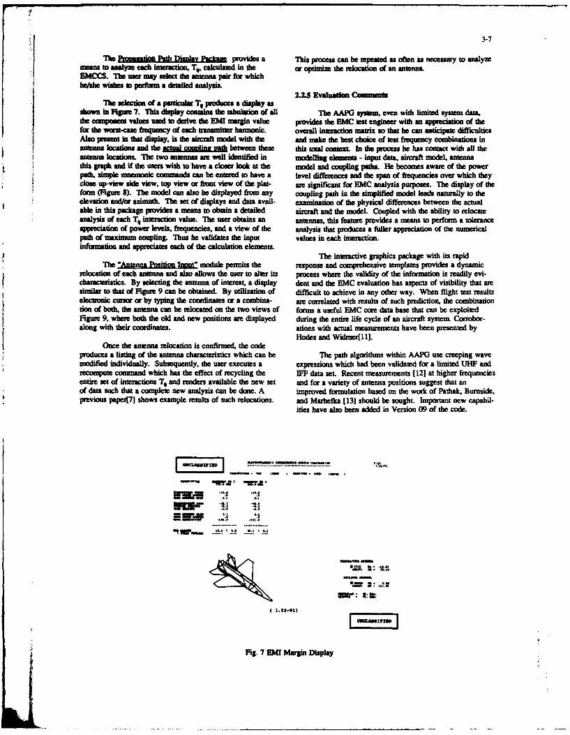
3-7
The PMoziu P h isdm a kpm provides a This process can be repeated as often as necessary to analyzemeans to analyze each interaction, To, calculated in the or optimize the relocation of an antenna.EMCCS. The me may select the antenna pair for whichWw wishes i perfnn a detailed analysis.
The selection of a particular T produces a display asshown in Fgure 7. Tis display contins die tabulation of aU The AAPO system, even with limited system data.
ie oIonen values used to derive the EMI margin value provides the EMC test engineer with an appreciation of thefor the wem-case fnequency o t each ranmitter harmonic, overall interaction matrix so that he can anticipate difficultiesAlso prsen in that display, is the airaft model with the and make the best chiwe of tet f1equency combinations insniana locations and the a W betwethb these this total roat! In the procss he has comact with all theantenna locatis. The two antennas are well identified in modelling elements - input data, aircraft model, antennathis graph and if the users wish to have a closer look at the model and coupling paths. lie becomes aware of the powerpath, simple mnemonic commands can be entered to have a level differences and the span of frequencies over which theyclose up-view side view, top view or front view of the plat- are significant for EMC analysis purposes. The display of theform (Figume 8). The model can also be displayed from any coupling path in the simplified model leads naturally to theelevation and/cr azimuth. The set of displays and data avail- examination of the physical differences between the actualable in this package provides a means to obtain a detailed aircraft and the model. Coupled with the ability to relocateanalysis of each To interaction value. The user obtains an antennas, this feature provides a means to perform a toleranceappeciation of power levels, frequencies, and a view of the analysis that produces a fuller appreciation of the numericalpath of maximum coupling. T1hus he validates the input values in each interaction.informio and appreciates each of the calculation elements.
The interactive graphics package with its rapidThe "Antenna Position Inout" module permits the response and comprehensive templates provides a dynamic
relocation of each antenna and also allows the user to alter its process where the validity of the information is readily evi-characteristics. By selecting the antenna of interest, a display dent and the EMC evaluation has aspects of visibility that aresimilar to that of Figure 9 can be obtained. By utilization of difficult to achieve in any other way. When flight test resultselectronic cursor or by typing the coordinates or a combina- are correlated with results of such prediction, the combinationtion of both, the antenna can be relocated on the two views of forms a useful EMC core data base that can be exploitedFigure 9, where both the old and new positions are displayed during the entire life cycle of an aircraft system. Corrobor-along with their coordinates. ations with actual measurements have been presented by
Hodes and Widnerf 1 1].
Once the antenna relocation is confirmed, the code
produces a listing of the antenna characteristics which can be The path algorithms within AAPG use creeping wavemodified individually. Subsequently, the user executes a expressions which had been validated for a limited UHF andrecompute command which has the effect of recycling the 1FF data set. Recent measurements [121 at higher frequenciesentire set of interactions TV and renders available the new set and for a variety of antenna positions suggest that anof data such that a complete new analysis can be done. A improved formulation based on the work of Pathak, Burnside,previous papetM shows example results of such relocations, and Marhefka [13] should be sought. Important new capabil-
ities have also been added in Version 09 of the code.
"' S --V 1 1a'- wg
" '..m, ,fl ,t. -IC* *
9,. I: ,,dll
Fg 7 M: Mg: Dsl
(1,0 inl-0 pta

3-8
Sam . CONK low"z ) bu , (2200aI a ( U.0 ) ld' a 3722 (lIll
Vww IEW! 011 ANONO 3103 m131
( 1.02-01)
Fig. 8 Cloe-up Propagation Path
POSITION UIT LM NAM Lin3 10rIZAGn STTION
OLD 0. 90. 225.I -2. 0. 507.
IF POSITION Is COMACT Ir 58c I UPLSS1-
Flit 9 Antenna Position Input
I

3-9
Moment methods applied electric field integral equa-tof AAPG V 09 tion formulations and GTD/UTD(Uniform Theory of Diffrac-
don) computer codes are the most commonly used instru-ments in computational modelling for low and high frequency
The three Unm of additional capability that hav ben antennas respectively. At the same time the potential of theadded in Version 09o AA G me: Gaussian aprximation of TIM method is being explored by several investigators. Thethe antenna p rn, rep ntatioi of &aWcft fuselage cro laer method is particularly attractive because of its potentialsectional shapes by multp points and the possibility to in the repesentaion of composit surfaces.include forward and aft cones which may also be tilted.
For frequencies above VHF, GTD/UTD techniques areFor directional ansennas, AAPG calculates the gain as VeiF, tple.Mlnt1 ecie i e chiv e s ofmo e
a function of angle by assumin a Gaussian falloff in two. bi plied whi etcn b dci eve l f mod eStgonal planes between the user input values for the main complexity which can be achieved by rD me1thods at pnes-beam d sidelobe pins. Tse assian functon in eah ent. Some of the codes described by Molinet are not widely
e pr ttt mavailable The Ohio State codes[15] are in wider use. How-!p l a e is p a m tri nd to th e -3 d B b e a m w idt o f t m i v r o t o th e e x m l s re o t d wiha mJI o ebeam in tht plane. An example is show in Fgr 10. ever, mstf eep th Gc
show results in the roll plane, rather than in the pitch plane orIn addition to the =cu cylinder, With or without flat voume y. Also, the modelling of complex antenna
bottor, the cross-section of the fuselage cylinder and co s source patterns is not completely developed in these codes.
can be specified as a series of radius values from the cenwoid Readers should consult the references for an appreciation ofat specific angles. These points am joined within the code by h potential and limitations of these methods.spline fitting. This provides more flexibility in the representa-don of modem complex aitft sbacs. The forward and aftcones a assumed to have the same cross-sections as th 3.1 Moient Methodsfuselage. An example of an Version 09 display is shown inFigures 1I(a) and Il(b). Ther ar now a number of computer codes such as
NEC[16], MININEC[17] and GEMACS[3] which are used for
A version of AAPGDI has been adapted for the prep- low frequency radiation analysis. They use moment methods
aration of input data sets for AAPG Version 09. to solve an electric field integral equation (EFIE) as appliedto a wire-grid representation of complex surfaces. NEC alsoallows a surface patch representation, and other surface patch
3. FIELD COMPUTATIONAL MODELLING METHODS codes[I8] are becoming available. NEC and MININEC aredistributed by the Applied Computational Electromagnetics
In addition to the system level analysis discussed Society(19] to their members. The following discussion
above, ther are many occasions where separate and mom applies to the development and use of wire-grid models with
detailed field or coupling computations must be undertaken. It the NEC code.is always useful to have techniques available for the calcula-tion of radiation patterns of antennas for performance assess-ment purposes and for use in deriving their approximations asinput for a system analysis.
aa p u DIM~lDIR-lila
• ..- 13..0S O490.0 I
F2-L VAIO I DOWDTVI llO.O D M
R&10 Antenn Pallets Display V.09 .! w

3-10
Bar 2-1
M. a -
-- °
... o.ar
( 4.01-oo)
r W' SSMZlUM
Fig. 11(a) EMI Margin Display V.09
..... - - " .
5.... a , -
iNCIUUFrz
Fig. I1I(b) EM Margin and Muee-Vm V.09

3-11
31.1 Tb. Electric Fiel Integral Equatiott
Con~e an inmteonnection Of highly-conducting w'ins, ofmadius much, munch less tan the wavelength. The current oneach wrverino an electic field. Thus in Fig. 12, theaxial surface curnt density 7i is assumed to be uniformly dis-tributed about the wine periphery, hence the cur.ent is1i 2xaJi. This current gime rise to an electric field component
at dhe observer in dhe direction I given by[ 161 E1ii*sjJV11;J~~s)d a BOUNOFRtYUO SE NT I*~v.~ i~~Gs~idiClS~l
where Tl is the characterstic impedance of the meihum, P is thewave number, and s s distance in direction I at the position ofthe observer. Kernel function G(s~s~) is given by (b)
G(s,,s) = I- f -jd# ~JiliJ)iI ) )I )mJix- f Rtcl
where R is the distance from the "source point" on the surface Fig. 13 A wire divided into segments, with various ratios ofof wire 0i to the observer. ff thee are N wires in the grid, the the segment length to tie radius. (a) ratio 8; (b) ratio 2,the!I component of the electric field at the observer due to all N (c) ratio 1/2wires is the "secondary field" and is given by
The "primary field" F,,, in a scattering problem is an incom-ing plane wave. The boundary condition for thin wires statesthat, at any point on any one of the wires, the axial componentof the electric field must he zer. Thus, if s, is a point on wire 31. Momnt Method Solution of the EFIESk. then the boundary conditron states that
The numerical solution of the EFIE for an antenna or scat--jf terer made up of an interconnection of thin wires is well-knownJG~~ a& s sds, in the liteure[20J. In the Numerical Electromagnetics
Code(NEC)[16,2 1,221, each wire of the model is subdivided-E'.'S)-1 into "segments", as illustrated in Fig. 13. The current on seg-
ment j of wire Oi is of the formThiis version of dhe EFIE is called Pocklington's Integral &jua- Ii~s = A,+R,5in~Q~s- si)+Cvcos. i-se))
Thus theme are three unknown complex-valued current ampli-tudes for each segment, and hence 3N. unknowns in all whereN, is the total number of segments. Contraints for determiningthe values of these unknowns are obtained by requiring that thecurrent and its derivative, the charge density, be continuousfunctions from segment to segment along each wire. At junc-tions of wires, Kirchoff's Current Law must be satisfied. Also,an excess charge is permitted to accumulate on the wires adja-cent to a junction, and to be distributed among the wires accord-
B ing to the King-Wu junction constint[l6,23]. These chargeand current constraints provide a set of Wl, equations.
MANThe remnaining set of'N. equations are obtained by using the"moment method" to satisfy the boundary condition. Thus a"match point" is defined at the center of each segment of theantenna, and the EFIE is enforced at that point. Each matchpoint provides one linea eqain that is, one row of a "mo-ment method' matrix. The NC od is formulated in such a
amaui way that the full set of 3N, linear equations is never explicitlyp assembled. Rtather, KCL and the charge density constraints am
enforced as the NWx,"moment method" matrix is assembled.The integration required by the -krnmel function is apoi
mated in two different ways in the NEC code. These we btinad by expanding the kernel functon as in infinit seies, in
Fig. 12 A "Okl *Wh catyin ur dmmsklyIl lives ris o poore of the wire radius. Retaining only die fRst surm obtainthe "thin wire kernel" or "normal kernel" apr~mtion.Thbsom aiic 11MU at the poddton of a observer, is e tlaiu o considering that the currndl along the
cnein ithe wire, avd that the *match point" is located onthe surface of the wire The "extended kernel" approximationretains two trsof the power series, and is more accurate.

3-12
3.13 Modellng Guidelines
The ansmption of "thin wires" made in deriving te EFM.the imdosof the kaee, and the approximatte solution
of the EFI by the "moment method" lead to restrictions on thegeometry of interconnection of "thin wires" that the NECprogram can solve correctly. Table 24pther these restrictions
as .Binsguielins".The guidelines we based on exten-sive Uss ol;esutsoaied by s oving simaple structures / - MRTCHwith the NEC code. Those presented here ar based both on the POINT
NEC User's Guide[21] and the athors' own experie c.NEC reqires that dke segments be sufficiently short in 2
trm of the wavelength. Segments comparable to X119 are usu-ally adeqtuat but segmnts shorter than XK20 wre required in ---- -----
critical regsi o the antenna. The wires must be "electricallythin": wins fatter than X30 are considered in error. The (a) match point close to the other wire's surface.approximations of the kernel place restrictions on the ratio ofthe segment length to the radius. If the "normal kernel" is used. MATCHthe segment length is best maintained at least 8 times the radius, POINTbut acceptable results are sometimes obtained for segments asshort as twice the radius. Fig. 13 illustrates segments oflength-to-radius ratio eight in part (a), and two in part (b). If the"extended kernel" is used, then the segment length is best kept -.twice the radius, but ser.nents as short as half the radius aresometimes acceptable, illustrated in Fig. 13(c).
At wire junctions, there e restrictions aimed at making thejoined segments not too dissimilar. The ratio of the longest seg- (b) match point inside the other wire's volume.ment to the shortest segment length at a junction must be lessthan five. The ratio of the fattest radius to the thinnest radiusmust be less than 10, with values less than five preferred. MATCH POINTBecause the NEC code does not full, use the "extended kernel"for segments which are part of wire junctions[16], the "normalkernel" rules for segment to radius ratio should be applied atjunctions. Table 2 considers that, for a segment which is part ofa wire junction, a segment length to radius ratio of six is fullya ceptable. (c) match point inside the other wire's volume.
Another important restriction applies at a wire junction.
The match point at the center of any segment at the junction Fig. 14 The match point must lie outside the volume of themust lie outside the volume of all the other wires at the jun- other wire at a wir junction.
tion, or else a "match point error" occurs. This is illustrated inFig. 14. Part (a) shows a junction of two wires, each havingtwo segments. The segments are relatively fat compared to thelength, which is a common occurrence in a wire grid. Thematch point on wire #1 lies barely outside the volume of wire#2. This is undesirable. Part (b) shows the wires meeting at ashallower angle. Now the match point lies inside wire #2, amatch point error. Part (c) shows the case of a short wire join- Modelling guidelines for the spacing of wires concern bothing a longer wire, in which the match point on the first segment gross errors, and the "thin wire" assumption. Fig. 15(a) shows aof the short wire lies inside the volume of the longer wire. It is pair of nearly-parallel wires which cross, that is, have a corn-an error to use two segments on the short wire, but it is one that mon point on their centerlines. In the NEC program, if theis easily made. If NEC is run on a configuration of wires common point is not a segment boundary on both wires, thenincluding some "match point errors", then the resulting currents NEC will not form a junction between the two wires, and amay be incorrect and can be quite misleading. Clearly this "crossed wires" error occurs. The configuration of Fig. 15(a)guideline limits the angle at which wires can join, in terms of also has "match point errors". A typical computer graphics dis-the segment length and the wire radius. play of a wire grid depicts wires by their centerlines, effective-
TABLE 2 iy hiding a crossed-wires error. It is essential that both wireradius and segment boundaries be shown on computer graphics,
SUMMARY OF THE MODELING GUIDELINES as in Fig. 15(a), if the user is to be able to see a crossed wiresA - segment length error.
a - wire radius If two wire centerlines pass closer than the sum of the wireX - wavelength radii, then the wires overlap and would have to be physically
INDIVIDUAL joined. Fig. 15(b) shows an "overlap error" for nearly-parallelSEOIMrS Warning Eno wires. NEC does not form junctions between wires which over-
lap in this fashion: they are treated as unconnected wires.p I0 < A < V5 A > V5 The "thin wire" assumption requires that the geometry of
the wires be such that the current flow on any wire is entirelyrdhu 30 < )Ja < 100 Wa < 30 axial, with no circumferential componen l Fuither, the axial
current density must be uniformly distributed about the wire.wnat o adu OJ </a <2 &a <03 periphery. Tb requires that wires be spaced sufficiently far
Sapart. It is difficult to obtain guidance from the literatur onjust how far. Ludwig[241 recommends several diametr.,NC.SCeartly the wires of Fig. 15(c) are too closely spaced to satisfythe "thin wire" assmption, even hough they do not overlap.
0111Is%* Z , > 5 ThIs neomer Is a "nr miss".fo Wrevksan occso 101011 comstucaed ofnety
perpendicular of forminnng junctionssedhs "do 5 <c a.wM..< 10 dw m 10 a tUsg-ltU If the point is a oupient bonday on both
wie.Such grids often contain error smuch that crossing onm nt mmt bomdariMs, hence contain "crossed wires
sem in" 2< Ma < 6 ft<2 errors. Then the wres an to joined by at propma, and thegrid does not ap= th model buIlder's

3-13
(}~: :~.~ i24-J ) 3.1.5 Model Development and ResultsThe application of the modelling guidelines to the
(a) crosed wires. creation of models for complex shapes such a aircraft isdiscussed in reference[25]. To assist in the error-fie are-
___________________anion of a wire-grid or surface patch model, die computer-aided system called DIDEC[271 has been developed. This
acronym means Digitize, Display, Edit and Conver Vertices17- ---- - --- e a ted by the digitization of points on aircraft drawings
or by numerical entry. The digitization process is accom-paned by a multi-ported display of the data. Vertices are
(b) overapping wires. joined to form the wires and wire segments of the wire grid.They can be colour-coded as to radius or length. Editing steps
-can add or delete vertices etc.. The final model data set is
convened to a NEC input data format by a simple transform-ation command.
--- Results of NEC wire-grid modelling for antennas onR( -- ---- .... ) ------------ ) -------- -)_......=.M aircraft, helicopters and ship's topside structures have been
presented in Lectue Serics 165 [281. One of the wire-grid
(c) a near miss. models which had been used is shown in Fig.16. It consistsof 371 wires and 400 segments and in the main, wire radii
Fig. 15 Wire spacing errors for nearly parallel wires. were selected based on the "equal area rule" with some vari-ations based on trade-offs with other working guidelines. The
A systematic examination of a wire *rid geometry file is segment length had been chosen to be 0.1 X at 15 MHz. This
required to ensure that all segments and junctions conform to model was executed at 2 MHz increments over the BF band
Table 2, that there are no "match point errors", and that the for radiation patterns to correspond to measurement frequen-spacing criteria are met. Visual inspection of graphics displays cies. Impedance computations are also compared therein withof various views of the wire grid have proven woefully inade- measured data. The results show that carefully developedquate for this purpose. Program CHECK[25] examines each models can provide reliable radiation patterns results over thewire, each junction and each wire pair to ensurre -ompliance. Amodel verified by CHECK is one that; ..- likely to lead to entire 2-30MHz band.
correct results when analysed with the H tatprograeq
The "modelling guidelines" a- ic .l in nature. They con- How are these computations related to EMC require-
cern individual segments, pairs of s&.gments at wire junctions, mets? Although initially related to systems communicationsand wire spacing on a scale o" a few wire radii. To use wires to performance alone, the results of these computations serve tomodel solid surfaces. guidelines of a more global nature are "validate" the computational model. As can be seen from therequired. AAPG discussion, such patterns refine the approximations
3.1.4 Wire Grid Vuidelnes used in this code. The models can be used for computationsof the near-field at other antenna and weapons locations. The
In replacing a highly-conducting, continuous surface with a computed current distributions on the wire-grid model also
grid of wires, fundamental questions arise. Wjat is the best result in an appreciation of HF antenna coupling as in thepi topology: triangular meshes or rectangular meshes? What case of the CP- 140 aircraft model shown[28]. Nw-fieldis the bandwidth of a wire grid of a given mesh size? What is intensities are also important for estimates of RADHAZthe best wire radius for i representing a continuous surface? conditions.The wire grid guidelines of Table 3 provide principles uponwhich a model can be designed. These guidelines are orientedtoward modelling complex structures such as ships or aircraft,of en with associated wire antennas. Whereas the 400 segment model shown in Fig. 16
A wire grid using square mesh cells requires fewer seg- would take approximately an hour on a CYBER 325 main-ments pa square wavelength to cover a surface than does a wire frame available during the development period, it now takesgrid using equilaserl-triangle mesh cells. Whether the trianp- approx. 567 secs. on a MIS desktop which is being evalu-
nrid offer wider bandwidth in return for the larger numberof segments has not been adequately explored[26. Table 3 rec- ated. Such laboratory computing power allows a new outlook
onmends an orthogonal grid with square mesh cells. on model development, less constrained by the number ofsegments and execution times.
TABLE 3WIRE GRID GUIDELIES An extensive re-exaumination of wir-grid modelling
guidelines (described above) had been undertaken for an RCS
1. Usmea recangular gid of wire oriented parallel to edges, projec(26]. Applied to the ame aircraft, these gudelineswith wes along edge. have resulted in the model shown in Fig.17. This min
2. oose tft segment length equal s U10 at the "elept" model contains 685 segments instead of 400 and
highest frquency of the bead. Keep die am of the grid takes 6128 se. on the MIPS machime. The model mor
cells compaeable o nJ1O). directly results in a finer structure at the feedpoints of
3. K !p cllssmT. Keep the call area constant, antennas which had been found critical in previous work.he LMNce feimtlnt ositaigot egrid. Thus there is every indication that this would be a safe4. -iaknnei ailn
J...ftion. approach for "ab initio" computational model evaluation and5. Put;;Mz_ w111011 wlme mis expected to flow. ume
7.Avok s en at very diow fl.7. Keep ths usau of amy segpma outside the volume ofmy other mpa .,
g. Use te qu1-ua ruin radius.9. All mehe In th grid must have peripheie longer than
'425.
&I9

3-14
L Fig. 16 Aircraft Model, 400 segments
Fig. 17 "Elegant" Aircraft Model, 685 segments
3.2 Transmission Line Modelling the resulting scattered voltages is defined by a scattering
matrix. The scattering matrix is given below for the voltagesTransmission-line modelling (TLM) is a numerical scattered at all four ports of the 2D node. The scattered
electromagnetic technique developed mainly by Johns [29,.- pulses immediately become incident voltages upon adjacent..,371 in the 70's and 80's. The basic solution provided by nodes. An analogy can be formed between voltages and
TLM is the time-domain variation of the fields in a defined currents on the transmission lines and electric and magneticregion of space. Within the region to be modelled. metal and fields in the region being modelled. The permittivity anddielectric objects can be defined and the boundaries of the permeability of the region are defined in the model by theregion can have various properties, such as perfectly conduct- capacitance and inductance per unit length of the transmissioning wall or a free space approximation. A very good intro- lines.duction to the basic theory behind TLM is provided byHoefer [38], but a brief outline will be presented here.
3.2.1 Outine of TLM V 1
The basis of the technique is Huygens' Principle [39] V3 V3which states that a wavefront can be male up of a number of V4 V4secondary radiators, each producing spherical wavelets.Thes wavelets form a new wavefront which in turn can bebroken down into a series of wavelets. In TLM, this principleis discre-divl in spece and time to allow solution on a con- At the bou txaries of a region a number of options areputer. Figure 18(a) shm the formation of a wavefront accor- available. In order to model a perfectly conducting wall, allding to Huygens' and this is shown in Figure 18(b) superim- transmission lines meeting the boundary are terminated in aposed upon a Cartesian mesh in a form suitable for TLM. short-circuit. Alternatively, it is possible to approximate aThe distance between nodes (dl) and the time taken for elec- free space boundary by terminating the lines in their intrinsicunmagneti pulses o travel from one node to the next (dt) at impedance. The free space condition works perfectly for anrelated by tde velocity of lIlgl incident wavefront perpendicular to the boundary, but bound-
ary reflections occur if the wave is incident at other angles.The 2D Cartesian mesh is made up of transmission It is possible to improve the free space boundary by messing
lines, with each node being the junction between four ans. the wavefront angle of incidence at each time step and adjust-mission lines. A typical node is shown in Figure 19 for the ing the terminating impedance accordingly. This computationjunction between parallel wir transmission-lines. The rela- has to be performed at every node along the boundary.tionship between a voltage pulse incident upon the node and
-ALI

3-15
Fig. 18(a) Wavefront divided into wavelets Fig. 18(b) Wavefront superimposed On TLMaccording to Huygens mesh showing approximate
scattering centres.
3
204
Fig. 19 TLM 2D node inade up of Parallel wiretransmission line.
ThMA is equally applicable to two and three-dimension-
A metal object within the mesh is modelled in a Simi- al problem. A schematic diagram of the full 3D node islar way to a perfectly conducting boundary, i.e. by short- given in Figure 20. Thfis is the most efficient and accuratecircuiting all the tranismission lines at the boundary of the 3D node and was derived by Johns [401. The basic 3D nodeobject. One of the advantages of the ThM technique is th has a 12412 scattering matrix, but modelling a lossy dielectricability to model dielectric and magnetic maerials. This is requires an 18x18 matrix. Therefore, storage is required forachieved by adding an extra stub transmission line at eah 18 terms at each node in a 3D mesh. Even a small problemnode within the object, where the admittance of the stub requires a relatively large amount of memory.determines the relative properties of the object. TLM is even Telnsi h Dnd ontitrccapabl of modeltling lossy dielectrics and this can be Tetasiso ie nte3 oed o nachieved in two ways. One psibilty istu nJsyts with each other and this allows them to have differing prop-misio lines between nodes. whilst dhe other used lory stubs erties. In this way, TLM can even model substances thatat each node to absorb energy .,- m th ms.~ Pi o*aeaioto rpris such as carbon-fibre composites.achnique is preferred in situations where the region to bemodelled is no oognos 3.U. Mesh Co..tuclon
Once a mesh has been set up, the initial stop is so set Th mes di~idni rtclt an accurate TLManl the voltoges a the nodes of the mesh to artt. Then an ouo Efetvlnugndsmstbuedomdla
Ol~iatifi i aplie andthetimedonam espose s ~wavefront accurately. Normally a A/10 criterion is used aslased. Typically, excitations wre Proucewd by setting up pulses the maximum node spacing per wavelength, If fewer nodesat a node at the initial time: siep. In this way it is possible to ame used, the wavefront velocity beomaes dispersed until the
edi te impulse response of a strcwm. Alternatively, it point is reached (at A/4 spacing) where no propagation occur.is possible to excise a line of ndswith pulses of identical Thi dispervion effec is very dependent upon the direction of
magnitude which varies over time as sin(wt) to give a plane propagation across the mesh, with maximum dispersion alongwave of angular frequency w. the axes of the mesh and no dispersion at 45o to the axes.

3-16
Fig. 20 TM 3D Node showing each arm made upof two parallel wire transmission lines.
3.2.3 Potential and Limitations
As a numerical technique, TLM has a number ofadvantages over some computational solutions. It is uncondi-tionally stable and computationally simple, the most complex
operation being a matrix multiplication. Furthermore, because The complex task of ensuring the electromagneticno matrix inversion is required, the condition of the matrix isunimportant. TLM can also solve certain types of problems compatibility of modem avionic/weapon systems can be made
relatively easily. Some of these, such as lossy dielectrics and more manageable by the effective use of numerical analysisreltivly asiy. omeof hes, sch s lssydieeclicsand and modelling techniques. The acquisition and use of com-anisotropic materials have already been mentioned. It is also pne codes tem analys is and r ecm
idealy uitd fr slvig pobles wth ntenalresnanes. puter codes for system analysis and electromagnetic modellingideally suited for solving problems with internal resonances, is rewarded by a clearer appreciation of the individual interac-
Disadvantages with TLM include difficulty in repre- tions between systems and by the definition of couplingsenting wires of diameter less than the node spacing (which mechanisms. Such use also involves and requires the gener-most wires are, without very high node density). It is also ation of a progressively improved data base of information ondifficult to excite a problem in a practical way, such as volt- equipment characteristics and radiating elements.age source on a structure. The large amount of informationstored at each node usually limits the size of a problem due to The effective use of these modem computational toolsthe finite computer storage available, does require the training of technical personnel in the their
use. Technical judgment must be developed by analysis ofTLM has many applications, both within electro- progressively more complex cases. Awareness of the validity
magnetics and outside. For example, it has been used to of the computational results at each step is most important.study fluid flow and diffusion problems [41]. Typical electro- The validation of computational models is now the subject ofmagnetic problems solved by TLM include waveguide propa- sub-committees of the IEEE Antennas and Propagationgation [29,30,32] and screened room resonances. Wave- Society and the Applied Computational Electromagneticsguides have been modelled with dielectric loading [42] and Society. A data base of canonical examples and real-worldbifurcations [29]. Other examples include direct coupling to a practical problems is being generated by ACES in order totransmission line and coupling through an aperture [43]. The assist the technical community in this task. It is importanttime domain nature of TLM makes it well suited to analysing that users become aw'e of the results and in turn share theirlightning strike and EMP problems. experiences so that duplication of effort and costly errors can
be avoided.Gothard, German and Riggs [44] use TLM to assess
the effect of RAM coating on a shipboard HF wire ropeantenna. The aim in this case is to minimise the RCS of the 5. ACKNOWLEDGEMENTSantenna to radars also on-board, thus minimising false targetsand pattern blockage for th radar. This uses near-field to This paper was prepared with the assistance of col-far-field transfonnation techniques to reduce the size of the leagues, Prof. C.W. Trueman and Dr. Miles Upton. TheTLM mesh. development of AAPG is supported by the Director General
of Aircraft Engineering and Maintenance of Canadian Depart-A number of techniques ar available to reduce the ment of National Defence under the technical direction of Mr.
storage required in a TLM problem. Grading the mesh is one Paul Campagna. Other computational modelling research ispossibility [45] whereby the X/10 node spacing requirement sponsored by the Defence Research Establishment Ottawacan be relaxed for regions of the mesh where the fields are (DREO). Drs. S. Kashyap and Tim Coyne sev as technicalunimportant. The other alternative is to use a technique authorities for this work.called diakoptics [46] in which two meshes can be solvedseparately and then joined together. This is applicable whereonly 9 small pit of a lap mesh is changed between sol- 6 REFERENCESutlons. The majorky of the problem can be solved once andstod and further modifications require only a solution for [1] MIL-E-6051, "Electromagnetic Compatibility Require-the part of the mesh that has been modified, ments, Systems", Military Specification

3-17
[21 MIL-HDBK-335, "Management and Design Guidance, [17] J.C. Logan and J. W. Rockway, " The New Mininec(Version 3): A Mini-Numerical ElectromagneticElcrmantc Radiation Harmdne for Air Launched Code", NOSC TD938, September 1986.
Ordnance Systems", Military Handbook
[181 Donald R. Wiltm and Shian-Uei Hwu, " Junctionj3] Spina, John, F. "The EMIC Concpt for Weapon Sys- Code User's Manual", Technical Report No. 87-18,
terns", Paper No.2, NATO/AGARD Lecture Series Applied Electromagnetics Laboratory, University ofNo. 116 on EMC, Fall 1981. Houston, May 30, 1989.
[41 Caprauo, Gerard, T., "An Intrasystem EMC Analysis [19] The Applied Computational Electromagnetic Society,Program", Paper No. 4, NATO/AGARD Lecture Series Dr. Richard K. Adler, Secretary, Naval PostgraduateNo. 116 on EMC, Fall 1981. School, Code 62AB, Monterey CA, 93943, U.S.A.
[51 Brock, Gary, et al. "Implementation of an SIF/EHF [201 Mitra, R., Editor, 'Numerical and Asymptotic Tech-Field-to-Wire Coupling Model into IEMCAP", Pro- niques in Electromagnetics", Sponger-Verlag. Newceedings of the IEEE 1988 International Symposium York, 1975.on Electromagnetic Compatibility, Seattle, Aug.2-4,1988, p. 470. [21] Burke, GJ. and Poggio, AJ." Numerical Electro-
magnetics Code, Method of Moments, Part lU:User's6] Capraro, Geraid et al., "Non-Average Power Receptor Guide", Tech Doc.116, Naval Electronics Systems
Model Development for the Intrasystem EMC Analysis Command, July 1977.
Program", Proceedings of the 8th International Zurich
Symposium and Technical Exhibition on Electromag- [22] Burke, GJ.,"Recent Advances in NEC: Applicationnetic Compatibility, 7-9 March 1989, pp.279-284. and Validation", AGARD Lectu Series No. 165,
[7] Kubina, Stanley J., "Computer Graphic Aids to October 1989.
Weapon Systems EMC Analysis", Paper No. 5, [23] Wu, T.T. and King, R.W.P.,"The Tapered Antenna andNATO/AGARI) Lecture Series No. 116, Fall 1981. its Application to the Junction Problem for Thin
[8] Friis, H. T., "A Note on a Simple Transmission For- Wires", IEEE Trans. on Antennas and Propagation,
mula", Proc. I.R.E., Vol. 34, pp. 254-256, May 1946. Vol. AP-24, pp.4 2 -4 4 , January 1976.
[9] Hasserjian and Ishimnaru, 'Excitation of a Con- [24] Ludwig, A., " Wire-Grid Modelling of Surfaces", IEEE[91 dHsuin aylndrsiaru 'Ecta n of a Csof Transactions on Antennas and Propagation, Vol. AP-ducting Cylindrical Surface of Large Ridius of 35, No.9, pp. 1045-1057, September 1987.Curvature', IRE Trans. Ant. & Prop., Vol. AP-10, pp. 264-273, May 1962. [25] Trueman, C.W. and Kubina S.J., "Verifying Wire-Grid
1101 Kouyoumjian and Pathak, 'A Uniform cino- Model Integrity with Program CHECK", ACES Jour-
metrical Theory of Diffraction for an Edge in a nl, Winter 1990,Vol.5 No.2, pp.17-42.
Perfectly Conducting Surface', Proc. IEEE, [261 Trueman, C.W. and Kubina, S.J.,"The Calculation ofVol. 62, No. 11, November, 1974. Radar Cross-Section ii the HF Band by Wire-Grid
[11 Hodes, H. and Widmer, P., "The Solution of Modelling", Tech Note No. TN-EMC-90-01, EMC
Real-World Aircraft EMC Problems Using the Laboratory, Concordia University, April 30, 1990.
AAPG Computer Program", IEEE Aerospace [27] Bhartia, P.,et al.,"Generation of Computer Models forSystems Conference, Dayton, 1982. the EMC Analysis of Large Systems",1984, Proc.
[12] Durham, E., "Analysis and Mearurmment of EMC Symp.,Tokyo.
EMI Coupling for Aircraft Mounted Antennas [28] Kubina, S. J., "Measurement and Computer Simulationat SHF/EHF", IEEE Symposium on EMC, of Antennas on Ships and Aircraft for Results of Oper-Atlanta, GA, August 1987. ational Reliability", 1989,AGARD LS-165 Proceed-
[13] Pathak, H., Burnside, D., and Marhefkt, J., "A Uni- ings, pp. 5-1-28.
form GTD Analysis of the Diffracti of Eiectmtag- [29] P.B. Johns and R.L. Beurle, "Numerical solution of 2-netic Waves by a Smooth Convex Surface", Trans. dimensional scattering problems using a transmission-MEE on Antennas and Propagation, Vol. AP-28, No. line matrix," Proc. Inst. Elec.Eng., vol.1 18, no.9, pp.1-
5, September P8. 203-1208, Sept. 1971.
[141 Molinet, F. A."GTD/UTD Brief History...-Recent [30] P.B. Johns, "Application of the transmission-lineAdvances - Applications to Antennas on Ships an matrix method to homogeneous waveguides of arbit-Aircrafl,1919,AGARD LS-165 Prec., 8-1-22.marxetot h oannsweulsofri-
rary cros. section," Proc. Inst. Elec. Eng., vol.119, no.
[15] Marboika, RJ. at al."Samom Antenna Siting Stdy... 8, pp. 1086-1091, Aug. 1972.
UsinS th NEC-USC V3.1",1990,Proc. ACES [ (311 P.B. Johns, "The solution of inhomogeneouswavegude problems using a transmission-line matrix,"
[161 Burk, 0. and Paggio, AJ." Numeical ectro- IEEE Tram. Microwave Theory Tech., vol. MTT-22,: ~pp.29215, Mar. 1974.
wgaes Code, Method of Moments P-wd-.Pp20-2rMr.194i De~tlptma-T7leoy~',Tech Doc. 16, Naval Eectnmics
Syssms Commua July 1977.

3-18
[321 S. Akhtarzad and P.B. Johns, "Numerical solution of [40] P.B. Johns, "A Symmetrical Condensed Node for thelossy waveguides: T.L.M. computer program," Elec- TLM Method," IEEE Trans Microwave Theory and
on, Lett., vol. 10, no. 15, pp.309-311, July 25, 1974. Tech., vol.35, no.4, pp.370-377, April 1987.
[33] P.B. Johns, "A new mathematical model to describe [41] P.B. Johns, "A Simple Explicit and Unconditionallythe physics of propaation," Radio Elecon. Eng., Stable Numerical Routine for the Solution of the Dif-
vol.44, no.12, pp.657-666 , Dec. 1974. fusion Equation," Int. J. Num. Meth. Eng., vol.ll,pp.1307-1328, 1977.
[34] S. Akhtarzad and P.B. Johns, "Solution of 6-compo- [42] S. Akhtarzad, "Analysis of lossy microwave structuresnent electromagnetic fields in three space dimensions and microstrip resonators by the TLM method," Ph.D.and time by the T.L.M. method," Elctron Lett, dissertation of Nottingham, England, July 1975.vol.10, no. 25/26, pp.535-537, Dec. 12, 1974.
[351 S. Akhtarzad and P.B. Johns, -Solution of Maxwell's [43] P. Naylor, C. Christopoulos and P.B. Johns, "Analysisequ35] on A th re sand dimeJns"ion od axwells of the Coupling of Electromagnetic Radiation intoequations in three space dimensions and time by the Wires using Transnission-Lne Modelling," Proc. ofTLM. method of analysis," Proc. Inst. Elec. Eng., vol the Fifth Int. Conf. on EMC, York, England, pp.129-122, no. 12, pp.1344-1348, Dec. 1975. 135, Oct. 1986.
[36] J.W. Bandler, P.B. Johns, and M.R.M. Rizk, "Trans- [44] G.K. Gothard, FJ. German and L.S. Riggs, "Analysismission-line modelling and sensitivity evaluation for of Radar Absorbent Material (RAM) Coated BF Wirelumped network simulation and design in the timeO Rope Antennas using the TLM Method," Proc. of thedomain," J. Franklin Inst., vol.304, no. 1, pp.15-23, Sixth Annual Review of Progress in Applied Computa-1977. tional Electromagnetics, Monterey, California, pp.163-
174, Match 1990.[371 P.B. Johns and M. O'Brien, "Use of the transmission-
line modelling (T.L.M.) method to solve non-linear [45] P. Saguet and E. Pic, "Le Maillage Rectangulaire et lelumped networks," Radio Electron, Eng., vol.50, Changement de Maille dans Ia Methode TLM en Deuxno.1/2, pp.59-70, Jan./Feb. 1980. Dimensions," Electron. Lett., vol.17, no.7, pp.277-278,
[38] W.J.R. Hoefer, "The Transmission-Line Matrix April 1981.
Method - Theory and Applications," IEEE Trans [46] P.B. Johns and K. Akhtarzad, "The Use of TimeMicrowave Theory and Tech.,vol.33, no.10, pp.882- Domain Diakoptics in Time Discrete Models of893, Oct. 1985. Fields," Int. J. Num. Meth. in Eng., vol.17, pp.1-14,
[39] C. Huygens, "Traite de ]a Lumiere" (Leiden, 1690) 1981.

4-1
CAnJES and CROSSTALK
Department:'University of KnteryLeington.K 4N
SUMheAobjective of this paper is to review theCrosstalkt Is the unintetiounal ectoanic standard m theaical moodels that wue d to predict
coupling between circuits which aecn ece parallel this crosstalL The relative acriecomputationalconductors that liem on ose t o ac Some comulezltides, and relatiInsights gained from fe modelexamples are wire in cable hanssso metl lad on wilIIdscused. N the cronfiaJ voltages are of sufficientPrinted-Circuit, Boards (PCB-s). This unintended magnitude andI. spectral content to cause unintendedinteraction betwee two or more circuts via their oeainof the h4Certain, altenaiv wift measures
elcrmgetic 11eld can cause interference problems. ma eused to reduce this crosstl to acp"levels.Signals 2 firoim one circuit that couple to another circuit will Tetpclmeasure sr to surround the emitter or theappear at the terminals of the devices that are receptor wire with a shield or to replace either wire with ainterconnected by the wires. If the signals are of twiste pair. Although It Is often assumed that thessufficient magiueo pcrlcnet hymycue creto measures will reduce the crostalk, this is notunintended operation of the device or a de gradation in its always the case Simpe explanation of how a shieldedperformance. A summary of the standard models used for wime Of a twisted pai Of wire will or will not reducepredctn crostalk in various tpe of onfuations is crosatalkt will he given. The key to understanding this is a
prsneLThe discusion williou on the reative low-freqeqc, inductive-capacitive coupling model. Inaccuacis, egins o aplicbilty ad cmpuatinal addition to providingjblight into the phenomenon, this
complexity; othe modls.A simple explanation of the simple mode allows ntodrpeiiosof the crosstalkability (or inability) of shielded wires and twisted pairs of that are obtainable with hand oal uts. This simplewires to reduce the crosstalk will also be given. lo-b~eq yN, fductve-capacitve coupling model will
LUMTODUCTION This paper is Intended to be a review of the variousCrosstalk is the unintentional coupling of aspects of crosstl To assis the reader in reviewing the
electromagnetic fields betw-e circuits th~at are onet pcable lIterature, an extensive lis of publications bybycnutr.FS I llustates this penomenon. A toonthis subjc is provided at the end of thistsource is connected to a load vi on pi of wiresper. These _sicssm regoped in categodes toAnother source is connected to its load via another pair of rusheocus on the applicable icreece. These referenceswires and the wires of each circuit are parallel and he In areCMY numere acodigt tectq .X% o Ms .close proximity. Currents flowing along thus wires create General, C. Per-nit-LegthParameters D. Cable
mantcfields that couple to the other circuit. Similarly, Harnees, B. Ribon Cabes F. Shielded ire~s, G.charges on the wires generate electric fields that couple to TwiSte Pairs of Wires, H. Effects of Incident Fields, Lthe other circuit. These electromagnetic fields induce Digital Computer Programs, ad J. Printed Circuitsignals in the two circuits. Portions of these Signals, Boarlds.
"' and *2152, appear at the inputs to each circuit. ELThe Multiosductor Tin misson Line (AM) ModelPrediction of these signals at the inputs to the circuits is The fadamental assumption In crossta predictionthe task In modeling crosstalk. The essential question is models is that the electric and magnetic fields surroundingwhether these unintended signals will cause the respective the conductors a5** a 2'Vaaawru Blgdmtrs gicloads to malfunction. i dd, structure in that the electric and maxnetic
theAmaxi (.1,3.1.This assumption0simplifies the modeling and is generally valid so long as the
£ -~~ cross-sectional dimensions of the line (wire separation and
------- cross-sectional els) are electkrily smlIe.,muhls* N ' than awavelength A, at the flequency of nest
* Crosstak urediction no"d have been Inetztdby the___________________author_ and weilstcd In the rencus. EprUetl data
R~* docamented nhsphlSim s. The pups of thispaper is tosummaslaetcmo_____Iorder tom ilsrate essential features of"ec
.A~I'S. I -- .. a -- ~mode we will coinsider a three-coaductor lin ilustrasedin Fig. 2. In general, cable bundles and coupled lands onPrinted-Circuit Boards (PCI's) Cosis of numerous
-- - -- - r 1----------- IO.
%to are*, 4 Ant tog ot I f
- - Z - JL--- _
II& 2. A the- -.uco trnmsso a

4-2
parallel conductors that interact. However, it has been vFE,(t). There are two types of crosstalk predictions thatshown that omitting consideration of the other parasitic mabedsr; fn-o i cstkadconductors aid cril*s leaving a th in-conductior lin may e sird;m time-dkmai c oeat and stends to give upper bounds or a worst case estimate Of the prediction refers to the prediction of the time-domaincrosstalk. Reference P.11, L.0 3 and ID-41 contain waeshapes of anvrqenydmithose data. These data also that the astalk In v 1 () v(t). Feunydmia random cable bunidle (cable harness) wherei the relative cosa prediction refers to the use of a sinusoidal source,positions of the wires are not known and var along the vS(t)=Vjsln((ii+ I), and the prediction of the mnagnitudebundle is quite sensitive to this relativewi90161 nPhsoftetad-aevlagVNLNadTherefore itis a~pl to compute bond and ptshfthisay-tt olaeV~ n
crostak rthe C 61tempinganecact prediction. VFE4#F. In this paper, we will be primarily interestedDetailed FORTRANI programs that compute the crosstalk in- eunydmi rotl snetevrosrgltrfor a geeral multiconductor line conals f(n1 liin areu en ecydomatlsincetevrosr.ltrparallel conductors are contained in P.1-L.41. For a large lm Th e In the mdeuyl i.2iL sdtocnienumber of coupled conductors, one ha no recourse but to number of different, practical configurations. Fig. 3utilise these types of digital computer program to ilsrtstpclwr-tp rs-cin
calclat th emstal an litlegonad isig ofi configurations. In all these configurtions, the generatorRestricting our discussion to the three-conducetor :o anreptrcduosanosirdtobwrsFi2 il d ow onsideabile Insghkt to otaned aa cnuctors of circular cylindrical cross section). The-M ilutaeteesnil taof the more gond codutonaillustrate. he We O thente ro n pgo u d j a e 2 ( o C n0 yidia
incident fields that are coupe to the line can also be v. i~ig lutapredi with these dtalcomp1uter programas, and thm shedI adtoa
predic edhtesied din PL-Lj 2 Pain( a be considered with our generalThe trecnctrline 2 osssofhro mdl h generator and receptor conductors are
farailel conductors of uniform oosen along thei rectangular cross-section conductors tyical of lands on-h en tle tha ise errl oa aie of the' Usg attwa) illustrates a doubli ded bosrd wherein
tha crs-etoa iw fteliea w ad a epae on both sides and connected throughdifferent positions along the ine are idnia Thrfr the board with Wa. Fig. 4(b) illustrates a less-commonlythe conductor crossections as well as the crossections of used board, the ingle-sted board with a ground plane onany surrounding dielectric wirmnenetesscka one side that ser:es as the reference conductor. This isinsulations must not vary along the line The conductors commnonly referred to in the microwaves literature as theare parallel to the x asis In a rectangular coordinate mirati confation F14. 4( fluftrtes thesystem, and the -nplan is perpendicular, to this direction mutInr= rhie wrn r ured atan onansteelcroanti ied. codigtote various layers within the board and connected with vias.TIM field structure asmtothe electric and mantc The general results that we Will obtain Apply to all thesefields have no component in th direction, configurations.axis. Ast feunyOf excitation is increasedsuhtathe lna rossetom dimsensions become electricallylarge, higher-order, nan-TIM field structures become Cb*MS ~flfURimportant. For typka line ceasetional hmnsion of @bOCWf)enigrhainterest, the TE idd structure will be the primary fieddstructure on the line up to frequencies on the order of aGHs so that the TIM model poieprdctions over a ~6
The three-conductior line of FIg. 2 consists of agenerator conducto, a recoptor conductor, and a refeec onenwoor..Jconductor The generator conductor along with the wirereference conductor comprise the generator circuft. ,- \~
Similarly, the receptor conductor aloe# with the reference ~7circuit Is driven at the left end by a source represented bya voltage source vqr(t), and a sources resistance P WResistors wifl be used to rpent siources and loads Reference CwAducoralthough the maoiy of the folowing results Will apply tomore coPAeN mpeae consstao Inductors, C'nrco
cpctors and controlled sourcess. generuator circuit is wr
terminated In a loa represented by the resistior RL. vrepresented by the resistors RNZ and R F. The Vsubscriponthegs loaids mdr to the near eid" and "Warend" resmPe!t to the end of the r C r elt nearest0to the so eof the gsubo irut. asumtio of~othe TIMmodle dpopmilo afowuto dsino, Alo COandIW
the curren" twft TtM. 1 Vlapof do geneator eeaWkconductor, VG(,) s~ rtegnno uutr-with rsetto Ido soeiwence condutor. The Current of OuWetothe generator audusctor, I(x0), Is defineid as AMoin to Wst eeelc adcothis righ lng th acnducto. UMWW a~d b olta ncurrent of the recespor conductor ar els 22d(~tand iR(xt). These vakWs and currents are dependent on 10 Aposition. & don So D ue6o, L TheobjactVein a Fi.&Conlo 1~rtosof pdlcroetel ;WYA is, gives theu c voltae, S)(t00 thed ofg who Ir55toaon ua hon picin eterminsaio resitees, %. RV sad Un, alongmewith tdo erm-=edue IMM k of the ie (coductorradii and =erai) and t h lIn e h X,~ pri" thenear-end aid es e asow2 voltages, vwzit) and

1001144Ciroitftod C06114190Scromflgution diomesosth at tiunwhes oe
Geeao eceo Goee R.eepptourtlegt Thedre it is sessntial in acomplete crossctif to be "h~ to obtain these
wemo 47 oo: quile draltof ft 5 In the Draft aAz"Le 0Ite-wbecomeSwd ou a oofle -d,ual partiago dffe euatos Sven by [A.1,B.1J:
Loop Recepto of Ful) GXt M(Xlt)ON 40 ) (in)-i VDv1(x-t) NO R(xlt) (ib)
]P5. 4. Cossectional wodsrations of PCB lad a1(Xlt) SDvxt OvR(X-t)
ooly mode of aon goid
MOILUR-1 0 irut.FaaI omnw the cane of tw-cnductor lines a A1that the $1n m edi nun Is lou1dthsetTherefore tee(aare no ioe I. heLe and it is said to be leukga Later iiV(xt) =N -L ~i(xt)we wMlmo ~rthow to iclude loomes An aa(bdectrlcslly-sml Ax section of the laisn 1 Pened by k~xt) - -C kV(xt)
the per-inlhgt parameters of self inductance, to andIand mutual inductance, 1m. The units of thene ane where the 2u1 vectors are
Henrs Ma meter &ad qepresent any section of the linerInt Isa unifr lin. These paaeesrpeetthe I 'G(X-tefitOf dhe transverse m agnt dfed. SMI*, ty, V(xt) -N [v1 (Xlt)J 3effects of the traneslctc fied are rrentdby
the per-uat-egt parmeters of self capeiacCj J;)=i ;) .b
parameters we Funds per meter. Thes e-aft-4ength jRXt
an appl a hr highe freoml soa li on terIlmoe Matrices and vCtogs wMl be denoted by boldface. The 2-2and p*pgfo Is th I N--I- -.- m ma e oNO ro aat odsl per-unit-length inductance matrix, k, and 2!2[A-l7i.1j Thrade refie 1trpfadjC-i h pe-nt-ength capacitance matrix. C, are VIveMbame computaon of these Parameters ix the caualmofFg .I sasue htte a L= zz G16 (4a)
Fo tetictoonth = muaty of the results. C ON c m I (4b)P&teconfiguatns own" ~ 4 wherein the f Cm (cR+ C)
conductors have recangular cosetin.there ae few c)dlosed-fom reut for th ru ni-eghprmtand numerical method@ must be omlydto determine The objcctsveain ediction is to solve these
them Afhov Owas smeua", jo n o th e m and -end voltages asthee slf laent whn he ircit ar no cuiied 4; vj(t)Nmv(O,t) and W~t)--vp(Jt) ixr a AiNehs
And co O ndMcPtheedo opp when the Bn do~~i ,are in dom Pgoulmly Furthermore thee are so similar repesnt te -donuis jelutden since the complete
the mls wd mutual donts (L1. And cra). wao( o these votmsae desired.Essentially, all of the inkormtion about time The kswcid ubsa o aeiisusumes the source
__________voltag"WIe 9U O liIs a sinsoid, IL&.vS(t).Vsin()m and the lin is Wn steady stae The
* *,*,,above transmission lin equations become h~r this case/' !~,.. A.l,B.1j
'I'm"~ i j~(x t(x) (50)
NOW di1i~y!X (5b)
I - where the pksse voltage and current vectors are denoted
Lg 5Thepe-ui-IesgthI--4embU zoieiVd) [VRxij
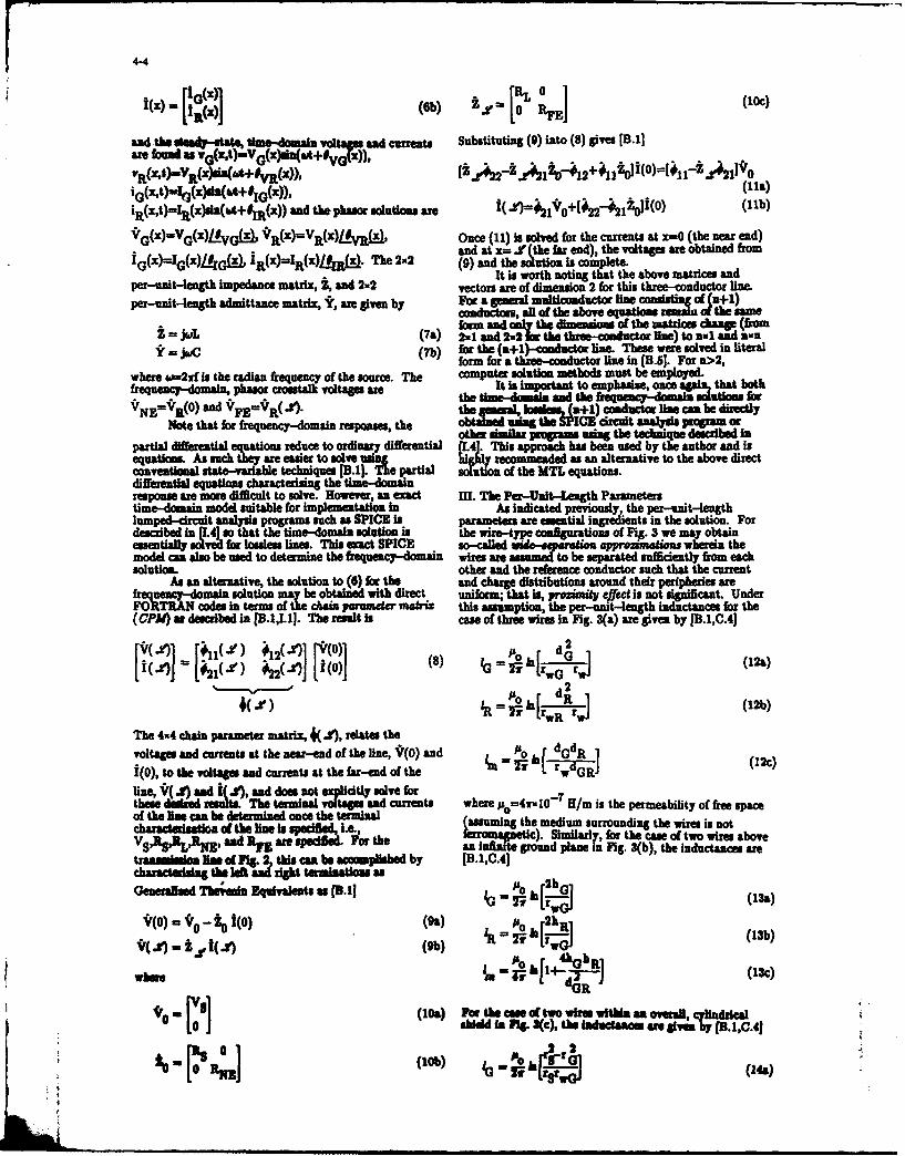
i 0 1~iVXx)9vt) (Oh) Ze -1 0 ies[ (10)
and the ded-ae hedmi ot adcurens Substituting ()it 8 ie B1are found U ((As -,. + M
iR(X't)=Ii(X)sW6~A+W(x and the phasor solutions awe (lo+2 2oI( )(11b)
V '(x)=V(X)IRyG~)p VRX=l()#Rx Once (11)1 ischled for the currents at x=-0 (tenered)and at x=i (he far end), the voltages are otnefrm
I'' I'"'' he 4 (9) and thesoution is complete.
per-nit-legth mpeanc matix, and2.2It is worth noting that the above matrices andPer-nitlenth mpeanc marix 1,and2-2vecorsare of dimension 2 for this three-conductor line.
per-anit-4ength admittance matrix, Yr, are given by For a general multioomductor line PMasi' *f j+1)conductors, all of the above equations 01 the ae
Z = jc.L (7a for and th iesosof the naoLW change (from2mb a7ad the throb-onuctot line) to al aid axnY= Le(7b) for the (n+1)-onductor line. These were solved in literal
form for a three-conductor line in [B.5). For a>2,where w=2f is the radian feunyof the source. The computer solution methods must be employed.frequency-domain, phaeor =runkvoltages are It is -mot-tt mhase, onesithat bt
tih oai andm th AN'Nf'R)an 'ERM 4 th -- I'-' - 'cnuco liI can be directly
Note that for frequency-domain responses, the otersilar i~c; propamo "sIn th te-nqu de rdi
partial differential equtons reduce to ordinary differential VA4. This approach has been used by the author and isequations. As such teyare easier to sleuigih rcm nddas an alternative to the above directconventional state-variable techniques [B.J. Th partial aouto of the MTL equations.differential equations chrat 6.nn the tm-dmiresponse are more difficult to sov. noever, an exact III. The Per-Unit-Length Parameterstime-domain model suitable for implementation in As indicated previously, the per-munit-lengthlumpe-ici analysis programs such as SPICE is parameters are essential ingredients in the solution. For
desribd I (4J o tatthe time-domain solutionl in the wire-type codfgurations of Fig. 3 we may obtainesenill ole frlosess lines. This andc SPICE scaldue-puw a poimtu whereinth
model ca also be used to determine the frequency-domain wires are assumeda : to bet se:parate su fficiently from eahsolution, other and the reference conductor such that the current
As an alternative, the solution to (6) for the and charge distributions around their peripheries arefmeny-main solution may be obtained with direct uniform, that is, proxkmit effect is not significant. UnderFORTERAN codes in terms of the di perimeter matiz this Assumption, the pet-unit-length inductances for the(CPM) as descid in [11.1,M). The result is case of three wires in Fig. 3(a) are given by [B.1,C.41
ri~dpr12( [()1 A,;... r dG[ 1(8) r dGw (12%)
The 4w4 chain parameter matrix, 4(4.f, relates thevoltages and currents at the near-end of the line, *(0) and -P~o IM dGdR -I(1ci(0), to the voltages and curruts at the far-end of the -1 L wline, V(J4 )d &W and does not expilcity solve for 7these deied reuLts.The terminal voltages and currents where pu=4r'107 H/rn is the permeability of free Spameof the line can be determied once the terminal (asmnthmeimurodnghewrssntVShaSRactul adio o IM th e s pelfed .~ fe*mpii) Simiarle for the cmn of two wires above
and I~ ar speified P'o thean Iinite- ground plneig. 3(b), the inductanes are*ss ass oef ft 2 this can be ap I d by 111.11C.41
charcterzingthe oft igh dt terminations asGeneraffsed Thalnd Equivalents a (3.11 o 2[h](i)
*(0) -t-i4 1(0) (9a) 00 2k~R (13b)
(b~) 4 ,j (13c)

4-5
Raaeea al'uhsae o he SpecwoCA eas of I00 f+1cadct in n be omoge medium IBCJ~r~I~ :(14b)G + = otho5sp U fts an vey simila to Onu above
2~i cs 0 l2 results.cl0seui-R, +roxmua 2a _*R /
aa be Ir analysi 0 4 a cs'G _] IVe usedA-IR O toIT mokre f3 r~rR) fre74uendis nhere
Vierb i ia dna oedls h a wir Isathe strcl a aresonI d.6 h vpdPspakng Sib e tionlo bu t~ thece _oirto ca monii 0 IS a ~aa rut that e lsth
be rasoabl aproxmatd a a omoeneus ne y aat thl* es =Ibn-et usndutosole fosremoing he Isula~onsleavng fee sam thn Omuld tettlnelnthadlme ssnl
pem Theit pa _d -0g caaitne fttewt-ye-NW hs nvldQ M bspm b* uof Fc n. he a e Obtained usin sehorttam "no 21 (a re smbls thechracter 6 s hedul n
speakaeine bcndndistinu idntt matix mo U)I" tauwit-I one of the mandaoaMn zrsesweeifoen romthel inu tance matri as e2yg ndcacsi
C-PRa (lIb)Oyu" IIreo i thae ontthe-onductor in ie soac F ing W5: n= sade M ] a e as Ipemt1vt c. L.mg. 104FP1heea baie snI WW~m caacts1 t [f (16)sear
0 i ad le t th lnieadado h mdl
where the veoiy o ogtin o eson di ineI -charcte5xe byp In c an Ii.h uniettymti
givhe n 1 ai diaona an elehee
fond and m thdce reatprmiit and
Formtevty can ste of thre Md toles roundig.3 homg eu an LupTmediumve oti rm~
-1g 6.) Lupe-iru pprxiat moel
-2jaL (ITS),bm~~~h adanag Ieoct usin theseaio moef wave tha th uei T
ande the line in ahnu thee reltivuPrmebiitya
pgfavthe urowfmuium i oft hou eou th thore masdac seto4b)mewt LVped TiorIt dum ,r wr e e ta h & e sac) ,C m a 1% .luSd.ic i &a p r cui od o im tee.d
-1 ~ ~The aeine tha sing thpese modds gis thatsdom(17d) t.(18)sCS in l (2 c u ar diderm"Itan oesth
Gor Istyalyth"WLed f the t asoam Umeao
~~~~te esI "hIJIw I ines tou 110601110 Of huhley="us~ is the hoiw that the Imopedne sawo

4-6
parlle doh h capacitances of the Lumped Pi no"el Simlifed________Moelthe~~ -- mplifieds Craitnl wiowitlt
ilAguatis altbi Lusupll azsl. Thus low A
Impedape e l "dto "Wder the cealdtai of lbS jWLm ILUmpe in mod" Ieffhctual wuh ighreasm _ _ _ r____N___loads tea to reaftder tInductances of thsU WTee++model WoffetaL A AC AI
V.e V (W) ~R pE '%V4C..FV V!E (W)
ixeUa lqaaese, taleedconductor (a) Froquene - Doam inl Model
51 () ws i"-a n B d juigs twis, in term ofs1 smOlm ta us~ th dumeas, in
.3. jb reuti elutfin showed tha Ihe o a"beedcedtoay simpl result ift ollowlig
theecodllaswon t=e (1) the &a am" weat_Was very 00euec tiniats na the L,!Iq
isTysot W~ X<44J , a3 lwdftermination nmeane ot 4hsshtntf frmthe line charcterstc *m Ths citaliae net+preciseau shown in .7 .10, andth gobftm f '~) Rj . V~)VFapplicabiltyof this [B model karather strong d
Nevrtelssthis vey simpe model yield crosstalkpredicos that are sufficent accurate ove a wide range
OfONfrqc iadimeadsons and (b) Time- Domain Model
The Simpl Modl of the receptor circuit Isillustrated in1g 7. Fig. 7(b) lustrates the tdme-dman 7i.. Simplified inductive-capaaitive coupling modelsmodel and a)g ?(allutatus the eanc-dmn
current and voltage oa nsgertr circuit which cat be v()= MN dvat (23)approxiate by N t) E_0
v() W RL vs(s) (191) v FEWt = MFE dUI (3b_____ it-
Therefore, the time-domain crosstalk voltages are directIG T) ! ~ t (lob) funton of the instantaneous derivatives of the sourc'
L ( voltage. Computed results will be given in the nextsection to illustrate the relative acurc of this model.
In other words, the frequency is sufficienly small that the Fig. 8 illustrates the frequency-doma variation Ofeffect of the generator line may be disregarded as can the crosstak voltage with frequency. The portions of theeffect of the receptor circuit on the generator circuit. crealkn coefficients in (22) which have the IDFor the frequency-domain response, the model of Fg. 7(a) superscrlts are refunrd to as the iuduliv couplingives cotiusi hra h otoswihhve the CAP
superscripts are referred to as the capacitineculn= (2o) con lutions These are so named because they depn
'N = wMNE VS either on the mWtua inductance or the mutulcpaiacVjMV5 (20b) between the geeao n eetor circuits. Osrei' n -jW M VS ig- tha ft lowmpedne" loads, the inductive
where th termsM n d E sgvnb coupling contribution dominates the capacitive couplingNdE ~ gvnb ot~uin Conversely, for 44gh-4mpedancel loads, the
ca"paitive copin Wotribuio dominates the inductiveIND CAP emm tion. In addition to being a simple
Mn =MNE + N (21a) =r~tl prediction model, this separation of the totalNE + MNEcrosstalk easily explaiins the effct of a shield or a twiste
IND CAP pair on the crosstalk as will be shown in later sections.M n Mpg + U7 3 (21b) VI. Compsrdson of the Prediction Accumaies of the Thre
Modelsamd We will new give an exmecomparing the
vewreiconacuacies waoe three models forIND Rwo I typil e nso of a thre-conductor line. The
M~3 nxjjsx~Lzm.Vup~j(22&) pOSedCtio of the three Models an verifed withCA1 RNR qK 1a at6. in the publications lite in the
CAP NZ~n I IL (2b) = = illnet be shown. For Illustation, we willU4E - ICN4% Ca22i conside the case of two wire above an Ininite pound
IND -jXpus mustrawe in Fig. 3Rb). The wires awe 2gag- - ~ ~ ~ (22c) strade (r~erwO 2 Ims or .321= f") voh ire
CAP;a are at a height above the groun Plane Of h(;mh 1-l.Sm.zL(2d) The wires aasumed to have insulation thicknsse of 15
Via 5 ii iq No ~Lmiead Mre touedaI o tAt the seo4 t ewum thevi i d' W3 sa or 1.4mm." tota Hune length Is
Inr M mar~ Waklupss"M decaie W" is on i Wads "s ms. Theter.na! Impe-aace ar ee to he eual to &W0:
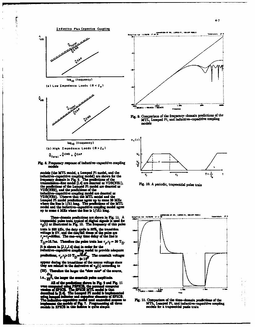
InAduct ive Plus Copacthve Coupling
3.w . ............ ........... .aw i a............ ..... .. a .. ......
A 10. . . . .
Vaga
log10 (frequency) V0
Wa Lowh Impedance Loads (R:,Z9)
indd atb aM aoK ar aepdPimd, n
inductve-capcitiv ana 1061 as Shpml pwteT tT
M a dntdg Fig- 10 Aomprioicf tefrequencdomaino redcinsoah
(b)de anig d uietmpednce Loads modelagre
T1iedelV pictosa hsI 1 a
.... .-p - - ...... ----- -~V -----( --------mralrAdo 2" aw ftil afhl ki n o
via aob inAr'a!-6j4 ta fMIdels (th M* mody Lumpe is mo% l SM Uwt
"Nr s Ven 6 xfol de o do aloeth rectla0m TM uwmpe Smo r dam oted o A Has
it Y j A ore daoteds
whrete i'r:~l .iu.. f heM-
=00 to sosWeete leI /.lq(2401 TVd do'a large Pa. aMw uWEof
IAL, ;k the bWS ulalk pfdoal &"His&o
Moa Is5d the Lue................. .h ....a-........ t.m de..........y; .
MsAdes "sum"~i INi toutl rwol.loprioatgsU00mipraton fd
(23).lh ahnu ahe hrw thepe Pie &ade ofutv-cpcv thesouce
04witOati afta.,u.A ha saionb r;dpe ri

4-8
VII. Judwdm of Losse Common- Impedance CouplingThegreloe moelsassumed that theline was
bshls shis the Has conductors are pewt conductors*and th =MinoAdn NMUiIs lawe.1.~ ILrn Rs Generator Conductor C.
losslssi me is fnkjplaly a Nissoaie = %mpfa forfrequmiss beow th tas rn. Howeme, there are
cases wL- the assumptias a i condutor s is Receptor Conductor RLamnd faZM camtd b usio tothe nductive +RFE
is illustrated inlg 12. Se PonUmwe the -_+ 's E
gesrAkt JW pDrec -:1=intecs of theL.eeec cntr I , we assume dw the referenc R,
caductor has a fintite but nommero conductivity giving it a Reference Conductorresistance prunit 1egh Suppose we further lump thatreference conductor, R.A o ~edsweetelndistvry bort ec tic oney, etmrdistautdmos of theUs
approximatelyNo
S (24)
t and appoimately all of this Rlows through the reference yElect romagnetic Coupling contributionconductor generating a voltage across it of /-opln Contribution
L Assumiing Perfect Conductors
(25) logl 0( Frequency
(b)This gives contributions to the near-.end and far-.end Fig. 12 Common-impedance coupling due to imperfect conductorscrosstalk voltages of
_ CI NE V Consider placing a shield around the receptor wireSN _R (26a) of the two wires above a ground plane in Fig. 3(a). The
= 'qZWFF, S ;1Tshield could also be placed around the generator wire. We.CI RFE V will examine the effect of the shield using the simple
V (26b) low-frequency, inductive--capacitive coupling model. TheFE Tr3 R O XS7*j emphassis will be on the frequency-domnain response. More
exact MTL models can be formulated and solved asThese crosstak contributions are referred to asdescribed in [F.1,F.2,F.4-F.7 and V.2,1.31. Also, the usualcefmaou-impdwnce coup,&# and are demoted with the lumped-ciit iterative mds such as the Lumped Pi
suesrpsCL These contributions are frenuency and Lumped Tee models as in Fig. 6 can be easily adaptedZand appear as a Nicore tat limits the to handle this case. Although the inductive-capacitive
llsatdin Fig. 2.The total croestalk can coupling modelcovers a smller frequenZ rag ha h
in(6 i h isdcie-aite ay lin in insig.t and will be used for that purpose.T is o course, an approidnmatwaofidd inF 13. Teafcapaicitainces be. the pnerator
lin lsse, ndin ulrImpretln cd u l wire and the pround plane and betwee the shield and themore exact wa ofivding the resistance of the ground plane are omitted sinc they provide second-orderconductors is to addl a per-sunlt-length resistance matrix effects. The total mutual capacitance, Cut is theto the time-domain UTI. equsoms in (2) or the per-unit-length mutual capaciftaince between the generatorfrequency-domain MTL equation in (5) IB-1J: wire and the shield multiplied by the line length. 'This can
be computed using the equtions of section MI, (13b),R - ~ ~~where we replace the radius of the reepo wie rwR,
r(rG+r0) (r 0t (27) with the overall radius of the shield. The mutualR - r (rftr 0 )Jcapacitance between the shield interior and the receptor
where ro and 'R1 ae sper-unIt-lenh resistances of wire, CS, is the per-unit-length capacitance of a coaxialthe gneator and receptor conductors, respectively, and ro cable multiplied by the line length [A.1JTlvethis th a -smt resstnc of U14 relerence eqluivalet circuit shown in Fig. 13. if m i
odco.The "yvluss of the zedstaces am usuall V u-W ( co upl~d t ige becoe Vowd la )sudIdest dlam shafin ct Is not well developed ovae terh aaiiecupigbcms[.,.1
lw ' dswhere these parameters substantially elect CA _AP R R(the~N in =a= m AP CA RBRZ VS (28)
the- an les sof dnt magnitude or Spectral which isesentialy hesame se with the shield removedc6ten t1 1,s istaimilmpisldprusiosima<<ma Now sppose
typlcaltw se 01:1 acti 4 that maOse to attempt to that the shiel is gIene at dther or bolth ends. f there ks ass* to telerahi leow 1 place a --... gdueulr-qfldHas~ sel amendll short, thae teerto did volleg, V53ti
wirle, the ue rWire or book IF.1-7 at~ replaice the ussawdav, o at aD points eloeg It and the capaitiveOR MtLe msem of thin coia nl if the *dW Is oae tensor
Paer we &eu h d wh th us of -- erof bzedsthee methods will or vii not reduce the *=ostalk.

4-9
Effect of Shield o Copo¢li-e Cophg Effel of Shield on XnduClivo Coupling
a s R ,
¢.I L
fPCAP IND I ND
Fig. I e& u8csdereef of h shi eld on
Now Nd us cosde h efcto hesiedo
inductive coallg. Consider Fig. A The geerator
circuit curn produces a magnetic flux that threads both
shield and this ground plane This induces a currentflowing bad s the shield, ISH, which produces a Fig. 14. Effect of a shield on inductive coupling
coun terating Aux that couples with and tends to reducethe not Aluxentatn the receptor circuit. The Simplified Model of Shieldedequiva let circuit ldo the receptor and shield circuits isshown in Fig. 15. The generator cunt, iG) induces a Receptor Wi.
source in the receptor circuit, JWLm/G, and a source in the
shield-gound plan circuit, JTLmiG, and the two mutual
inductace between the generator circuit and the receptor L,. .circuit ad between the enerptor circuit and the shield ,.circuit me equl ecu se the receptor conductor isshon with the shied. This mutual inductace can beoo.sou onutted re (1t). The selminduct andoe in theshield-ground plane circuit, LSE, ca be computed from a lSie
(13b) by repltwng the receptor wire radius with the shield _ c po
radius. The s held cunt induc. s a source, j LsHaSH in e
the receptor circuit. It can be shown that the mutualinductance between the sheld-jround plue circuit andthe reptc -powd plane circuit are identical since thereceptor wire Ilocatsd on the axis of the shield [F.1-F.7.The total resistance of the shield is denoted a RSH. This Fig. 15. Simplified model for inductive coupling to ashielded receptor wirecircuit can be solved to yield
*IND= R NZ RSH (29&) e. if it is oude. at both ends.VNE - " R Kj~hJ Am RWTJ wDL VS9 This simple analysi lan d=When the addition of a.IND VE RSH shield will or will not reduce crosalk Consider Fig. 17.vFZ - - ...Ii m je.jm- jsVs (29b) The nottions in this figure denote the sield uro
at either and (00) the sdd poundsd at the er ndonl y(0, Wthe Q hl ded at the far end nly (OS),
Forfrequencieswhom RsI>, this1,P; 'on reduces SRI ed rounded at both ends (SS). TotWlFor reqences her thi euweslonred c atl is again the sum of the inductive sad capacitive
to th wi the dddd removed and the shield has no coupling contributions. Suppos the terminationct oiMdNct agico or t hebequenckes . Above impedances are low mpedasceeu. prior t tle adition oftug Ix' M x the finductive COo~pln the sield, the inductive o will dominate the
omesi ieuq as Illustrated Inig.16. capacitive coupin. If the is added sdth aroundAD doti mmo ladsy sue h generator WINe or thes re str'r) seoneathe ON"u WUIinu4 both 06-toAlbw a AWel only one end, only theonpdlu "9em will S~dCd
current ~ 6 Nofe sRahgtesil to produe thi and since th tWta couj nis lad so reduction, incmnteachgmx.ifth sumi Is ntgmuatboth the total coplilne sillIf d Is
6166 aw f omflvend the a01f idasso m'unded at bothends t capacitive wil fuaa" hbdlw AVs, b.-te removed but the inductive conpi{ be-dcisgi eill hle a 01114 of exciltationl is above wo=RI /Lsn. Thus for ki-pedance lea a
bhWM tb ao de;: tll.%.l /r ,-- i~d

4-10
Effect of Shield Grounding on slieddwiflredimthetotalcouplieg Dalyif the shildisInductive Coupling panded at bothends andOnl yabOve WO. Conversely
consider the case of high-4apedance loads. Here thecaatie copln dominates the inductive Coarilili
i; hed~diadded. Supposea si~teither the generator wite or the receptor wire and isprounded only at one end. The capacitive coupling is
eoedbut dainct wus dominant the total coupling IsIND reduced (othe inductive corNO level wihiAIJ unchanged). Now iteshlds ru at 11 both ends,
b ~ and the frequency Is above wthe total Coupling will beb/ J" further --educed above w since the inductive coupling is
reduced. Thu ls h dnz loads, a shield will'0reduce the total cc ithesdidk Maiidat
les n nadaoew if it is = at both ens&Co dqet7 placing a shield arounad a wire may of my
Shield Grounded not reduce tI total crosstalk and the abovet notionof ot Edsexplain when they will or will not reduce crstl
MX Twisted PairsThe second option is to replace either the generator
b, wire or the receptor wire with a twisted pair. Considerreplacing the receptor wire with a twisted pair. There are
4____ ______________ basically two coniguraitlone ilustrated In Fig. IS. In theunabriaced cojgrrsie the far end is ungrunded and
wLfs one end of the near end is grounded. Both ends are usuallyRSH wLSHnot prounded in order to avoid pround loops. In the
F~g 18 Efectof hied goudin onindctie cuplng balanced configurali^ each wire of the twistpr seesFig 16 Efectof hied goudin onindctie cuplng the same impedance to ground.Thsi om y
for a shielded receptor wire implemented with center-tapped transformers (BALUNS)or with dual-input, dual-output operational aiapliers(line drivers and ie civr). We will concentre on a
Effect of Shield Grounding simplified explanation of the couplin0to twisted pairsusing the inductive-capacitive coupling notions. Thereader is referred to [G. 1-G. 101 for a more detailed
0'- discussion.
------- SS Unbalanced
0
Low fmeoc Load
Low-nvednce oadsNote: Grounded at only one end to avoidground loops.
AV
Owl balanced
Each wife of twisted peig sees somef lopedenee tO greund at eec see.
lilli-ZOPMee Loads
J~.17. 26t of dhli grounding an cirosstalk to a I&.18 Twe Pi comipatlUs for unbalanced and*IdMs whoa baaned mods

4-11
The twisted pair inherently affects only the Effect of Twisted Pair oninductive coupling in the manne shown in Fig. 19. The IdcieCUlncurrent of the generator circuit produces a flux that IdcieCulnthreads the loops of the twisted pair of the receptor circuit.This induces opposing emira in adjacent loops as illustratedin Fig. 20 where Yk dnote the length of a "half twist".Similarly, the capacitive coupling i represented as currentsources attached to each wire of the pAir in the fashion ofFig. 7. Nf we "untwist" the twisted par, we arrive at themodel shown in Fig. 21. Observe that the afs inadjacent lostend to cancel 1eavizsthe net inductivecoupling a=ha of one half twis t. us the Inductivecoupling has been reduced by the twist. On the otherhand, the current sources attached to the prounded wireare shorted out so that the total capacitive coupling isapproximately uangd Thus the twist does not, initself reduce the caitive coupling. In order to reducethe capacitive coupling, balanced loaods such as in Fig. 18must be used.
Thesenationsawe sumnnarixed in Fig. 22 for the 000cas of an unbalanced twisted pair. This figure comparesthe difference in crosstalk between the receptor wirngbeing an "untwisted pair" and being a twisted par. Forthe untwisted pair, either inductive or capacitive coupling Fig. 19. Effect of a twisted pair on inductive couplingwill again be dominant. For "low-impedance" loads,assume that inductive coupling dominates capacitive Smlfe oe fTitdPicoupling prior to twistinghMe pair ofwires to produce theSm ife MolofTitdPr
twisted pair. Twisting the wires reduces onythe . ~- X-inductive coupling so that the total coupling drops to the A A
Capacitive coupln level of teoriia onfiguration (the EEuntwisted pair). Conversely, fo "ig-im-1pedance" loads,assum that capacitive coupling do=iae inductivecoupling prior to twisting te pair of wires to produce the Y2 2 Eztwiste pair. Again twisting the wires reduces theinductive coupling component but does not substantiallychange the C pctive coupling component so that the______________reductionaofth nductive coupling b the twist does not/ / / / / / /cas te otal ugh tow chne7hus lor theunbalanced case, use ci a twse pair will reduce the total(aInutvcrosstalk c..! Lx "low-impedance loads. Since balancing(aInutethe loads wilreduce capacitive coupling ia the balancedcase, use ofia twisted pair will reduce Zt total crosstalk
Referece (1-.0contain experimental data thatconfirm these notions.
This paper has summarized the methods for w cPredicting and reducizin 1rostalk. The fundamental/ / / / / / / /prediction mocdel is the distributed-parameter, UTL
mdlwhose fkndamental assumption is that the TEM ()Cpctvmode Of propagation is the dominant mode of propagation ()Cpctvon the line. Typcly this is satisfied for lines whose i.2.Smlfidmdlo opin oatitdpi
crosecloal imnsinsare much less than a waveength ~.2.Smlfe oe fculn oatitdpior for frequencies typically up to the GHs range. All othermodels are 1% ns to this model. The unrealistic to expect that fiber optic cables will solve thelumpe-ici Ierative models Attempt to APprxm crosutalkt problem i h erftr ic
theMTLmoel orfreuenie whrethe lnlethis metallic-conductor cables are in considerable use, and aelectrically Short. The applicabe freuecy ragedpends complete conversion to fiber-optic cables is not realistic toon the type ofi ns For cablie bundes up to 5Mn length, expect. Some use of fiber optic cables is being made in thethese meoda are valid up to som 10 UHL. For Shorter newe weapon systets, but there is a large inventory thatcables they are valid to higher frequcis. For typical uses metallic conductor cables Aivh ae not likely to bePCB's thesm valid to hundreds di WMs [J.21. replaced in any preat volume. Therefore we will continue
CosirbeIsgti andwith the to have to deal with this problem of crosstalk betweeninductive-esadtlv e opling moe.Ti oe svld mtli-~dco am"e far some time in the future.for Uss tha are very short, dectrinally, and are weaklycopld These rsstrictiosis seem to be sever but for nRN S
pracica mmo~sthe alow rasoabl preictons (Publicatious by the a&tho comoemingovr iikntbqesq aneand are am e to tas IsM ie and crossta)
handCSIUISU.. bMT andlumed-crcut Ierativemodmis geally ms be solved with dgtAlcmpue . OKcod.Ted kW~v. " mo mfl.1 Isriteli to' Decslal Sewed
&nwa abeC~si d I adift o ca sheld tion, M ra-1,N I wihS.A.or d- a *4 w91 w ime crosstal. jA.21 Analysis of Linsa Ckircs, Mc=raw Hl oseY 98.
A nd ft b WM w oth lt sot that ams Of
me allcnductors *ar IN"ass w b-aptic cables. [B.11 "Application of Multicaductor Transmission LineThai fseti v~iral 4:9600~ betwemese T ~y to the Prediction of Cable Coupling - Vl.1I-typo of calus Amy and al spgwill teplcatthe Multiconductor Transmission Linehor, Technical
enswhere tU"'bis are co litd to scre"to Report, Rome Air Developmet Centt" Oiffss AFB, KY,adapt to Conventional signal processing. However, it is RADC-TR-76--l01, Aprf 1978. (A02302)

4-12
Unbalanced Untwisted Pair vs Twisted Pair
A A V '
VHSA1
E~ EI
,'77/777777IND (Twisted)
Inductive Capacitive
hon bat twist E, - 2
+A
VNE( RE FE
N ,iz) k N 1 1+I 12
2 2 Shorted ouv
Inductive Coupling. -~ that of one half twistCapacitive Coupting: - ame as untwisted pair
N - haf twstsIND (Twisted
Fig. 21. Untwisting the twisted pair
capacitive v Inductive
[8.21 "Lumped Model Approxinations of Transmission Mg. 22. Effect of.twist on inductive and capactive couplingLines: Effect of Load Impedances on Accuracy", Technical for an untwisted pair compared to a twisted pairReport, Rome Air Development Center, Griffis AFB,N.Y., RADC-TR-82-286, Vol. IV E, August 1984 (with
WWEverett Ill)B. OnU!iiorm Multimode Transmission Lines", IEEE
Tran~s.oan Microwave Theory and Techniques, Vol. [B.121 "A Simple Technique for Estimating rstl"MTT-1, N. 8 pp.558658,Augst 173.1983 IEEE International Symposium on Electromagnetic
[B.1 "Useful Matrix Chain Parameter Identities for the Coinptibility, Washington, D.C., Augut 1983.Analysis of Multicionductor Transmissi T3on lines", IEEE ,.3 r;Lumped Circuit Modeling of Transmission Lines",
as Miicrowave Theory and Techniques, Vol. 1985 IEEE International Symposium on ElectromagneticMTT-23 No9, 1p.756-760, September 1975. Compatibility, Wakefield, M A, Aug.,1985 (with L.JB .51 "Soution o the Transmission Line Equations for Monroe).Thie-Couductor Lines in Homogeneous Media", IEEETrans. am --croanei Compatibility, Vol. iMC-20, C. PER-UNIT-LENGTH PARAMETERSNo. 1 p.21-22 Fe.1978. IC.I] "Computation of the Capacitance Matrix for[B.1 'oputto of Crosstalk in a Multiconductor Dlelectnc-Coted Wires" Technical Report, Rome Air
Tasiion Line, EEm Trans. OR Electroagnetic Development Center, Grihus AFB, NY,Compa~i~y Vol. EMC-23, No. 4, pp. -358 N-fov. RADC-TR-74-69, March 1974, with J.C. Clements.1981. [ C.21 "Applications of Multiconductor Transmission Line
aBT O the Suecutiom of Inductive and Capacitive Telyto the Prediction of Cable Coupling - VolII -uinlursti = Prediction Models" IEETraa. on Computation of the Capacitance Matricis for Ribbon-e - -uT~ COmpatibility, Vol. EMO-24, No. 3, pp. Cables", Technical Repoht, Brnm Air Development
[B.81 "Estimatiom of Crosstalk in Three-Conductor 1976 with A.E. Feaher April
Cos VLkCN t4, Nov. 1964.' Cylndrca COU4TinsA o lcrmplcCoupling in Branched CmaIltVo. EM671?, No. 4, pp. -248.Anlio ectla smouma OR oebr17 with J.40. Clae ts ad A.T.Ad s)
LT Ati Of ,Crosta Prediction adbacaasMatrce from t Gesialsed-mbilomatlilt Zed* Swisela-IF8, No. 4, Wp 175-18, Nar.
196 wti Fahe)Tt11141111111111 UMrn An OvervIew", I.fMC PoStaticlCapacitance
ohmnd ITedoals Eibition Clcltle via the Metbdof Mmts OUThwL ORMarc 1963- lo 1I n -ozd No. 1,p,

4-13
C.6] "Application of Moment Methods to the G.21 "Crosstalk in Twisted-Wire Circuits", Technicalt of Ribbon Cables", Computer and eport, Rome Air Development Center, Griffin AFB, NY,
Eectrical mineemnE Vol. 4, pp. 173-184, 1977 (with RADC-TR-82-286, Vol. IV C, November 1982 (withA.E. Feather . M.B. Jolly).LC.J7 "Application of Moment Methods to the 1G.3] "Prediction of Crostalk in Balanced, Twisted PairCharacteuisation of Ribbon Cables", International Circuits" Technical Reprt Rom Air DevelopmentSymposium on Innovative Numerical Analysis in Applied Center, Griffins AFB Y, RADC-TR-82-286, Vol. IV D,Engineering Science, Paris, France, May 1977 (with A.E. August 1984 (with D. Koopman).Feather). [G.41 "Prediction of Crosstalk Involving Twisted Pairs of
Wires, Part I A Transmission Line Model for TwistedD. CABLE HARNESSES Wire Pirs", liEE Trans. aT "Applications of Multiconductor Transmission Line Compatbility (with J.A. McKnight), V . C-21, No.theory to the Prediction of Cable Coupling - Vol III - 2, %. 92-105, May 1979.
Prediction of Crosstalk in Random Cable Bundles", G.5 "Prediction of Crostalk Involving Twisted Pairs ofTechnical Report, Rome Air Development Center, Griffins ires, Part H, A Simplified, Low-Frequency PredictionAPB, N.Y., RADC-TR-76-101, February 1977. Model", (with J.A. McKnight), IEEE Tram. on
A O 816) . Ele tro ma ei C orn blity, V ol. E M C- -21, N o. 2, pp.1D.21 "e tivity of Multiconductor Cable Coupling to 0- 14 , !ay 17.paP ameter Variations", 1974 IEEE International [9.61 "Sensitivity of Croetalk in Twisted-Pair Circuits to
Symposium on Electromanetic Compatibility, July Line Twist", (with M. Joly), IEEE Trans. on16-18, San Francisco, California. Electroma c Compatibility, Vol. EMC-24, No. 3, pp.[D.31 "Senitivity of Crostalk to Variations in Wire 359-364, Auust 1982.
[9.71 "Sensitivity of Coupling to Balanced, Twisted PairPosition in Cable Bundles", 1987 International Symposium Lines to Line Twist", (with D. Koopman) 1983and Technical Exhibition on Electromagnetic International Symposium sad Technical Exhibition onCompatibilit 7, Zurich, Switzerland. Electromagnetic Compatibility, Zurich, Switzerland,[D.4j "Sensitivity of Crostalk to Variations in Wire March 1983.Position in Cable Bundles", 1987 IEEE International [G.8] "Prediction of Croutalk in Twisted Pairs of Wires, ASymposium on Electromagnetic Compatibility, Atlanta, Simplified, Low-Frequency Model", IEEE InternationalGA, September 1987. Symposium on Electromagnetic Compatibility, Atlanta,
GA, June 1978.E. RIBBON CABLES IG.9] "Coupling to Twisted-Pair Transmission Lines", 4th[E.I] "Applications of Multiconductor Transmission Line Symposium and Technical Exhibition on ElectromagneticTheory to the Prediction of Cable Coupling - Vol. IV - Compatibility, Zurich, Switzerland, March 1981.Prediction of Crosstalk in Ribbon Cables", Technical [G.10] "Crosstalk in Balanced, Twisted-Pair Circuits",Report, Rome Air Development Center, Griffiss AFB, NY, (with M.B. Jolly) 1981 IEEE International Symposium onRADC-TR-76-101, February 1978. (A53548) Electromagnetic Compatibility, Boulder, CO, August[E.2] "Prediction of Crosstalk in Ribbon Cables: 1981.
oarSon of Model Predictions and Experimentres Trans. on Electromagnetic Compatibility, H. EFFECTS OF INCIDENT FIELDSVol. EMC-20, No. 3, pp. 394-406, August 1978. H.I] "Applications of Multiconductor Transmission Lide[E.31 "Prediction of Crostalk in Ribbon Cables", IEEE Theory to the Prediction of Cable Coupling - Vol. VI - AInternational Symposium on Electromagnetic Digital Computer Program for Determining TerminalCompatibility, Atlanta, GA, June 1978. Currents Induced in a Multiconductor Transmission Line
by an Incident Electromagnetic Field", Technical Report,F. SHIELDED WIRES Rome Air Development Center, Griffin AFB, NY,[F.I] "Applications of Multiconductor Transmission Line RADC-TR-76-101, February 1978. (A053560)Theory to the Prediction of Cable Coupling - Vol. VII - [H.21 "Coupling of Electromagnetic Fields ontoPrediction of Crosstalk Involving Braided-Shield Cables", Transmission Lines: A Comparison of the TransmissionTechnical Report Rome Air Development Center, Griffis Line Model and the Method of Moments" TechnicalAFB, NY, RADd--TR-76-101, August 1980. Report, Rome Air Development, Griffin FB, NY, RADC-[F.21 "Prediction of Crostalk in Flatpack, Coaxial TR-82-286, Vol. IV A, November 1982 (with ILT.Cables", Technical Report, Rome Air Development Abraham).Center, Griffin AFB NY, RADC-TR- 82-286, Vol. IV (R.3] "Efficient Numerical Computation of the FrequencyF, December, 1984 (ith WE. Beech). Response of Cables luminated by an Electromagnetic
3F.3 "Effect of Pigtails on Crosstalk to Braided-Shield Field", IEEE Trans. on Microwave Theory andCables", IEEE Trans. on E ro c Compatibility, Techniques, Vol. MTT-22, No.4, pp. 454-457, April 1974.Vol. EMC-22, No. 3, pp. 161-172, August 1980. T-4] "Frequency Response of Multiconductor(F.4) "Transmission-Line Modeling of Shielded Wires for Transmission Lines uminated by an IncidentCrosstalk Prediction", IEEE Transactions on Electromagnetic Field" IEE Traun. oncEectlroma c Compatibility, Vol. EMC-23, No. 4, pp. Compatibility, Vol. EMC-18, No. 4, pp. 183-190, Nov.345-351 Nov 1981. 1976.[5 "Efect of Pitails on Coupin to Shielded Wires", ?,.5] "Frequency Resonse of Multiconductor
E Internati Sym um on Electromagnetic ransmission Lines "minsted by an IncidentPomdpatibility, San CrosstCA Oct. 1979. Electromagnetic Field", 1975 IEEE nternational
[F.61 EPrediction of C ak In Iratpack, Coaxial Symposium on Elecromaec Compatibility, SanCabin" (with WE. Beech), 1984 IEE International Antonio, TX, October, 1975.Symposum on Electromagnetic Compatibility, San [R.6] "WIRE, A Digital Computer Program forAntonio Texas, April 1984. Determining Terminal Currents Induced on a(F.]7 "Literal Solution of the Transmission-Line Equations Multiconductor Transmission Line by an IncidentforShielded Wires", 1990 IEEE International Symposium Electromagnetic field", 1978 National Aerospace andon Electromagnetic Compatibility, Wuhington, DC, Electronics Convention, Dayton, Ohio, May 1978.August 1900 (with B.A. lowee). ..- "Co upliu of Electroman Fields to Trasmision
.P.thIT.. Abraham) 1981 IEEE InternationalG. TWISTED PAIRS oF WMu S Symposium on Electromagnetic Compatibility, Boulder,beory to the Prediction of Cable Coupling - Vol. V - [H.8] "coupling of Electromagetic Fields to Trnsmison
Pne, (with erF. Rnck) 1082 IEEE InternationalPrediction of Crostalk Involving Twisted Wire Pain", araoAm on Electrom e Comptiity, SantaTechnical Report, Rome Air Development CenterS Gyps iam, CA, September 12.AFB, NY, RADC.-TR-76--101, February 1978. (A53559) 1.91 "Bounds on Currents Induced in Transmission Lines
by Incident Fields", (with D.R. Bush), 1984 IEEESOUTHEASCON, Louisville, KY, April 1984.

4-14
L DIGITAL COMPUTE PROGRAMS j. PRINTED CIRCUIT BOARDS[1.1 NApplicatoms of Mulioductor Transmlulson Line IJ.1lPModlng Crosstalk on Printed Circuit Boards",
to the Pdit of Cable Couplin - Vol. VII - Techncal Repkt, Rome Air Development Coater GrimsDiga Computer Propam fw the Anal of AFB, NY RAD,-TR--107, July 16 (WivW.Mulliconductor Tnsab Linm, Technical Report Everett (i-t).Rome Air Devdopment Center, Ods AFE, Rome of, odein c Printed Circuit Boards fr theRAD -.TR-7-101, July 197?. (A046662) Cmuak nd Ground Dop" IBM Journal
-] )SHIELD, ADi'tal Compu Prrm of Reear and Dewdopoma, Vol. 3, ft 1, January,computingr a Betwem e Ca , Technical 19.Report, Rome Air Developmet Center, s AFB, NY, 1331 "Printed Circuit Board RMCN, 1985 InternationalRADC-TR--2-6, Vol. TV B, November 196. posium and Technical Exhibition on Electromagnetic[1.31 "SHIELD - A Dital Com puter Proam rthe CM it I.udck, Switzeland, March IM.Predictio Of Crolttl to Sldle als ' 1983 all4 trrduted irit Board CrowuWk, 1985 IEEEInternational Sym um nd Ceal Exhibition on Ite6ratonal S poimm n Electro 196neicElectromagnetic Compatibility, Zurich, Switserland, Compatibility, Wskefdd,Man., Aug. 1985 (with W. W.March 1983. Everett, HI).R.4] "A Simple SPICE Model for Coupled TransmissionLines", 1988 IEEE International Symposium onElectromagnetic Compatibility, Seattle, WA, September1988.

5-1
GROUNDING, SHIELDING AND BONDING
by Pmf. IrJ.CantysseKiJl.WV., Zeedijk 101, B-8400 Oostende, Belium
In the EKC-design of systems and circuits, both grounding and shielding are related to the couplingmechanisms of the system with (radiated) Electromagnetic Fields. Grounding is more related to thesource or victim circuit (or system) and is determining the characteristic of the coupling mechanismbetween fields and currents/voltages.Shielding is a way of interacting in the radiation path of on electromagnetic field. In this text,basic principles and practical design rules will be discussed.
0. Introduction
Considering an electronic system, and lookingfor the coupling mechanisms with the "outside" g slt 2world, two important coupling paths from circuitlevel into ambient fields (or vice-versa) maybe distinguished. This is sketched infig. 0.1.
- -----------~~~joint ""
Fig. 1.1. Common mode impedance coupling.
The presence of a ground wire or plane is alsoinfluencing the characteristic impedance of a
/couple of wires. The value of this characte-rIground ristic impedance is important for matching
Fig. 0.1. : Coupling of systems to fields, sources and loads, or to a avid us wanted re-flections (ex. in binary bus systems). This
It should be mentionned that "system" problem is discussed in another paper. See
means any electronic system or circuit, fig. 1.2.
Referring to fig. 0.1., the sketchedPCB's are again a system by thimselves. Id? (a) S,,e BIm.-LJ Tr-I, ,,,* Sy1tM 1.1
And the given system can be a subassembly I'
in a larger context. This means that all DM
characteristics and design rules and con- IU: t,,.
clusions are valid at all levels of an Wvw
electronic circuit. As an example should (blft. Gus PWIt-Ltf Sy,1t
be mentionned that coupling characteris-tics of a couple of wires are exactlydetermined by the same physical properties
as it is for tracks on a PCB. The same +may be said for shielding subassemblicsin a large* system compared with the 1016it --shielding of the whole system. So, general
conclusions have to be translated everytime into the typical parameters at theapropiated level of the design. Fig. 1.2. : Characteristic impedance for
matching bus systems.1. Grounding And thirdly, the presence of a ground return
In electronics, grounding is a very general wire is influencing the crosstalk between wiresword and concept, and is used to describe or tracks. Fig. 1.3. sketches crosstalk geometry.
a lot of techniques. The only comon item Also this effect is discussed in other papers.
in all applications is that a system isconnected to the point of the referencepotential used in the system. For a lot ofapplications, this means the "earth", but
not any time.
I.I. What not ?
In electronic design, grounding is used Qfor a lot of targets. First of all, it g13is us"d as the conductor for the returncirrent of data and signals or of thepower system. When the same wire or trackis used for the return-current of different
subsystems, problems may occur because of Fig. 1.3. : Xtalk geometry of wires or tracks.these currents causing a voltage dropover the impedance of the wire (fig. 1.1). Grounding is a very important tool to avoidThis effect is called comon impedance problems from the mentionned effects. However,and will be discussed in another paper. grounding is also very important in the cou-
pling of systems to electromagnetic fields.

5-2
1.2. Ground loops. For the emission problems, it is easily seenAs might be seen from fig. 1.4., connecting that 3 important parameters are influencingtsomihtes seher cthe radiated level, frequency f, current Itwo systems together causes some current (or voltage E) and the ioop area A. Both,
flowing from the first to the second one. frquencg f and tel are diretly
Depending on the convection mode used, frequency f and current-level I are directly
the return current is flowing over the earth/ related to the electronic design choice of
ground (fig. 1.4.), or through a well defined clock , logic family, power consumptio
return wire. disc of decoupling capacitors, ....The loop area has only to do with the "mecha-nical" design, i.e. layout on PCB, wiring ofsubassemblies, cable connection between sys-tems,.... The area to be considered is the
-Oka area of the loop formed by the wire (onPCB-track) carrying the current and theground wire (track, plane) carrying thereturn current. An example is given in fig. 1.5.
- 'u-" Also for the susceptibility or receivingproblem, nearly the same parameters are comingin : field level (E or H), frequency and looparea. The difference is however that fieldlevel and frequency are coming from the"unknown" ambient and are not directly re-lated to the system under consideration. Theonly design parameter which may be taken intoaccount, and is under the control of the
Fig. 1.4. Return current flowing over earth, system designer, is the loop area A. The factthat designers have to deal with unknown ambient
In any case, a kind of loop is created where levels makes the susceptibility problem harderthe same current is flowing through. This than the emission one.generates a magnetic field, which is radiated For both cases may be concluded that thein the ambient. Otherwise, a noosy electro- problems are not only depending on the electro-magnetic ambient induces in such a loop an nic design itself (ex. choice of components),induced voltage. For both cases (emission, but also on the mechanical design, normaly thereception), characteristics of the coupling generation of current loops. Because the groundmechanism may be derived from the theory of is used to carry the return current (in asym-loop anteraia's. From electromagnetic wave metrical system), the physical emplacement oftheory, it follows (see fig. 1.5) : the ground is the dominant factor in this
- emission : near field H 1 /3.A.I loop coupling mechanism between fields (E/H)
A 1 and the system (V/I).far field H f2. A.I However the effect is depending of the trans-
d mission mode used in a system (Common mode/
6f A.E Differential mode). But as a general conclu-d sion may be stated that loop area's should be
- reception E i 2 Uo A dH/dt i i. AoE/120 minimised, and a good choice of the routing(Pane wave) of the grounding wires or planes is crucial
for the good working of a system.
1.3. Common mode/ Differential mode
Systems are reacting to the ambient in adifferent way, following a common or diffe-Irential mode coupling. This will be discussedin detail in another paper. However, somecharacteristics are summarised. In fig. 1.6,basic concepts of CM/DM are sketched, andalso the coupling area with the ambient. Itis clear that for a normal concept of systems,the C.-loop area is dominant.Minimising this loop area is one of the veryimportant design parameters in circuits andsystems by routing apropiately the ground-reference.
%Jt s o .I Im
Fig. 1.5.: Radiation from a loop: Fig. 1.6. : Q/DN coupling.
- 9/2 field radiation at distanceof 3a from a I e
2 1oo l l a A
- induced voltage in I ca? loopby plane wave I V/2
I,|
,Ac

5-3
It should be noted that on a PCB, a CM system For the control of hightning and ESD-effects,is used for routing, even bringing in a comon and also for the faraday-shielding (of trans-impedance problem. For DH-like systems, an formers, ...), it is essential for a goodunwanted ground loop may induce an interfering working that the connection between parts ofsigual, due to unbalances in the DM-system. the system and the ground/earth is done at aOpening such "unwanted" loops may be done by really low impedance level. This problem is"ungounding" system (ex. not connecting known as banding. It is referred to sectionIIPCB's to the shielding box). Minimising loop for the discussion of banding techniques.area's may be achieved by using good, large 1.5. Conclusions.ground planes, with a well known positionreferred to the system. An example is given Grounding is a very important action in elec-in fig. 1.7. for a small PCB and for a large tronic system design, because of the influencecomputer system. of the ground in different topics related to:
1I safety and shock-protection__ lightning and ESD-control
T T faraday-shieldingcommon mode loop control* talk and transmission-line relatedcharacteristics
As a common requirement, for all applications,
is the need of a low impedance ground reference.This means not only a low resistance, but alsoa low inductance for both the ground referenceand the banding wires. This is a hard requi-rement for ambients and interference signalswith a spectrum holding high frequencies.
Fig. 1.7. : Ground planes. And as a general rule, all grounding andearthing references and connections may not
1.4. Other grounding rules, be mixed when they are related to differentIn the sections above, a lot of grounding topics, requirements, systems or subassemblics.rules were mentionned with respect to the In practica, this means a separate groundelectronic system itself. Other reasons reference for critical signals for analog andfor grounding (or referencing to earth) digital signals, for noisy systems, .-.are related to safety and shielding. It All these separated wires shouldn't only beshould also be noted that grounding is connected at the REAL reference point of thenot always connecting a system to the system (Single poln-tStar grounding).earth. Some reasons for grounding are : And as a last point, it should be mentionned
that the mechanical design and layout isSShock and safety hazard control crucial for the good working of a system
- lightning (earthing): ground-reference acting as the return- power system failures current conductor, creating a ground loop
E141-control : (coupling to the ambient EM fields).
- control of a current discharge * crosstalk, shielding and characteristicparth for ESD impedance of wires /cables/tracks on
- faraday-shield return reference PCB's, backplanes and subsystems.- cosmon-nmode loop control. controlled routing of discharge currents
When looking for the last item, this may of ESD/lightning and safety earth.be in conflict with the other requirements A typical example is the pigtail connectionfor safety (ex. opening a ground-loop), to cable shields, ESD-earths, safety earthsSafety, shock and lightning require a low- of main filters, ... creating a loop-antennaimpedance connection to the earth, and even inside the system to protect and causing ina good distribution over the system of this this way a new source of EMI problems insteadearth-reference. of offering a solution, even using a shieldedAs a general rule, it should be s9,,ed tht box.there should be NO mixing of grounwing/earthing connectl-ns related to differenttopics. As a typical example can be mention- 2. Shielding.ned the direct dischange current of an ESD-hazard. This current may flow through the Tackling interference problems may be done atreference ground of asystem, causing 3 levels : by acting on the source level bydammage or at least common impedance induced reducing the emission levels and spectrum.voltage (see fig. 1.8.). By acting on the victim level by reducing the
susceptibility (or increasing the immunity).And by acting on the transmission path. Thislatter action is depending on the couplingpath. For conduction problems, the use of
I filtering techniques must be considered. Forradiation problems, the use of shielding tech-niques is required.Iecause shielding is direct-ly related to radiation, electromasgnetic fieldtheory is concerned with. In fig. 2.1., anexample is given of a radiated spectrum, cop-pared with a typical imission-level standard.
Fig. 1.8.: KID discharge paths.

5-4
A -Starting from Maxwell theory, it may be cal-culated using Schelkunoff theory that global
: -J shielding is given by
t - SEf) 3(BOB)" RB) * (dB) dB)
M A111 A Owl where : R- -20 log 11(1 + p)(I - p) 1
A- 8.68 t V;woi-7e - 8.68 t/8
t B- 20 log II I - Oexp(-2t/8)I, ,, _ 8 - skin depth -
i - 2n frequency
a - conductivity of the material
f1 - IL'. ur - permeability of material
fig. 2.1. Emission spectru from a PCB. -- reflection coefficient . Zmetal- ZwaveZmetal+ Zwave
2.1. Basic Shielding Theory For materials where t 48 , SE - R + B
Basic shielding theory is starting from max- t > 8, SE - R + Awell equations. Depending on the model usedfor the shielding material or housing, three Note that 6 is frequency dependant.different techniques are used in practice As in classical transmission line theory," Schelkunoff, using a transmission-line the reflection coefficient is function of
like model and an infinite flot panel the ratio of characteristic impedances inof shielding material the material. Electromagnetic wave theoryof sieldng ateralgives:
" Koden, using a unifor ous field dis- g v s Utribution fnr closed boxes Zwave F-Coo 120n - 3770-
* circuit theory, using induced currentsin the materials and an equivalent Zair for far field(plane wave)circuit diagram.
Referring to practical box design, Koden X v for near field, E-fieldand circuit theory are giving best theo- 0retical results. But referring to themeasuring techniques for evaluating theShielding Effectiveness of materials, the a e orZwave T- 0for near field,H-fieldSchelkunoff-theory is best fitting to these R Itomeasurement methods. In general, Zwave is noted as Zwave -When a wave is impinging on a b-rrier, areflection is generated. kPart of the wave is transmitted through othe barrier. During this transmission, thewave may be attenuated. Multiple reflec-tions may be generated, due to the second Zmetal 0 + ( ) + j)transition of the barrier to the aim. 02Global attenuation or shielding value willbe a combination of these 3 effects The distinction between E/H field condi-
tions are made for near field conditions,- first reflection (R) i.e. the distance r from source to barrier- multiple reflections (B) is smaller than X/2u (X- wavelength).- attenuations (A) This is discussed in another paper.
This is sketched in fig. 2.2. The wave impedance is sketched in fig. 2.3as a function of frequency, distance to the
Air Conductve shield Air source and type of source.
-U- INI \(pwrP 3 ) hF ))
#4gw fid FW use
fig. 2.2. Shielding of materials.
Shielding effectiveness (8R) is definedas the ratio of the field strength in apoint I without and with the shielding IMmaterial. This refers to the definitionof insertion loss (I.L.) in circuit theory.
Mm A w fedI

*Absorption loss (A) -8.68 t/6log (e b*eNse 2 in0 t - thickness of the
material
alo R canstM to2 m 6 -skin depth .
*1WIt follows that A is a function of
o fm -- conductivity CY of the materialX R - permeability u of the material
- frequency (a0101 C______ LOD______two - thickness t of the material
grImymb A sntdrcl related to the near field/
farfied cndiion ofthe system.
log Own' I Zinc) IS Re-reflection loss (B) - 20 logI I - 0 exp(-2t/8)11I
4 ~ C M a fcltf u2 Nft This factor B is a function of
d"M - conductivity ca3 pwftm- permeability IL
2 - frequency at- thickness t
.513t An example of the Re-reflection component Bo Rou- is given in fig. 2.6.
Muiflipll eclions compormat B (dB)
am1 Oa o LID low imo two MO
Fig.2.3.: Wave impedance. 5.
Given the above expressions, it follows thatIfor the SI-value SI - R 4 A + B, all three tiimeI anP components are depending on some parameters03
CReflection loss (R)- -20 log II(I.0XI-0)II-I
4 Zestsl 1wvv i*, , o .m mo eo eTiZmetal zweveyz frequency (Wk)
- &IZWV -t Fig. 2.6.: Re-reflection B as function of26etal/Zuave +1 frequency
However, the three factors don't have a similar______relationship to the mentionned parameters or
zwe k IVEg variables. It means that different sets of
Zutl- __ om___ values (R, A, 3) may occur, giving the sameZt (I+J)TwV j/200 amount of SE - R + A + 3. This combination for
SE is given in fig. 2.7 for a typical example,It follows that R is a function of for far field conditions. It is seen that for
distance source to barrier (near field/ these conditions SE is nearly f lot up tofar feld)higher frequencies, where the absorption comn-
- conductivity a of the material pnn eoe h oiato*
- permeability of the materiel The Re-reflection effect disappears also auto-- frequency ws mtatically when the thickness t of the conduc-
t is not directly related to the thick- tive layer come in the same order as the
ness of the material, skin depth 8, because of the absorption (orA example of the Reflection component is attenuation) effect in the material.
give in ig. .4.Approximate formilas are given in the nextgive in ig. .4.table.
I.Absorpioness A ()
apse
5 VfeAm an sw 'am 001e41 SAO" s
asI as* SAO 14164 s"a" sums.
fig. 2.4. 8 Reflection lose a function 4i.1.11:"Aof frequemcy
I
i.25 A
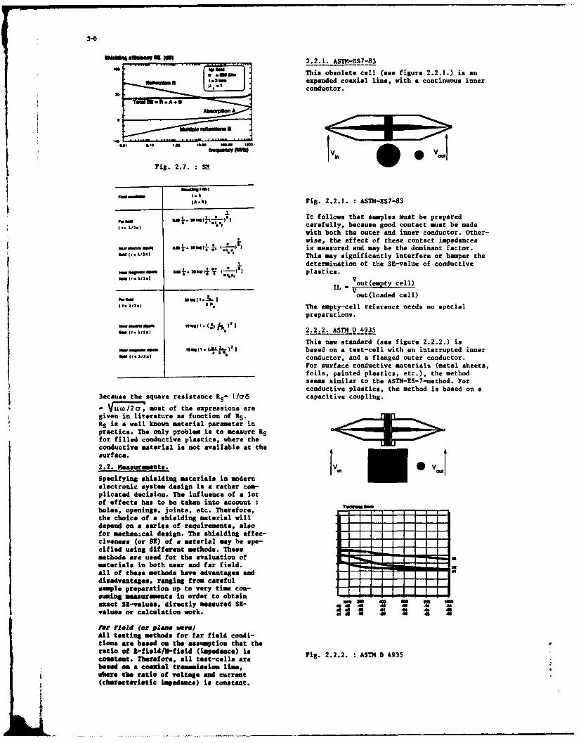
_____________________IN__M_ 2.2.1. ASTM-ES7-83
to* This obsolete cell (see figure 2.2.1.) is anexpanded coaxial line, with a continuous innerconductor.
-~ Fig. 2.7. *SEV(AN)Fig. 2.2.1. ASTh4-ES7-83
Lot It follows that samples must be prepared*~bM ~carefully, because good contact must be made
with both the outer and inner conductor. Other-wise, the effect of these contact impedances
N-%dss@ *uin I* (..=we1I is measured and may be the dominant factor.This may significantly interfere or hamper the
~ j. determination of the SE-value of conductiveIM . mJ".Foo e- -n IT mt plastics.
VAN X12l.) *%,IL -V out(emptycel
"M Muq.k 2 V Vout(loadad cell)(I 1.)2R The empty-cell reference needs no special
preparations.
I,. *2.2.2. ASTM D 4935
This new standard (see figure 2.2.2.) is0hWAWe"W "%I. (.L1.),I based on a test-cell with an interrupted inner
ft (r. W.1) conductor, and a flanged outer conductor.For surface conductive materials (metal sheets,
________ ________________foils, painted plastics, etc.), the methodseems similar to the ASTM-ES-7-uethod. Forconductive plastics, the method is based on a
Because the square resistance RS- 1/oI8 capacitive coupling.
- Vuw /2 c , moat of the expressions aregiven in literature as funation of RS.raRS is a well known material parameter inpractice. The only problem is to measure Rfor filled conductive plastics, where theconductive material is not available at thesurface.
2.2. Measurements. Vi -Specifying shielding materials in modern
electronic system design is a rather com-plicated decision. The influence of a lotof effects has to be taken into accountholes, openings, joints, etc. Therefore,the choice of a shielding material will-- - -----
depend on a series of requirements, also---- - ---
for mechanical design. The shielding effec--- - -----
tivenese (or SI) of a material my be spe-cified using different methods. These-- - -----
methods are used for the evaluation of---materials in both near and far field. ~*All of those methods have advantages and ---- '
disadvantages, ranging from careful--- 1 -- --
emple proeration up to very time con-- ------
asinngmeaauroments in order to obtain ----- -
exact SI-values, directly measured SI- Wk 211 4 M s Svalues or calculation work. Is 1 48 M .6 . 1
Par Field (or plan. ay.All testing methods for far field condi-tions are based on the assumption that theratio of I-field/U-field (impedance) isFi.2 .. SHD43comstant. Therefore, all test-cells are i.222 ASh043baso a coaxial tramemiseton lime,
wbere the ratio of voltage and current(characteristic impedance) is constant.

5-7
Samples must completely cover the outerlonges and no contact is allowed between thehalves of the cell. (Plastic screws must beused).The reference measurement for the empty cellis done with a reference sample in the cell,covering only the flanges and the inner con-ductor. This method is very complicated V. Vbecause for every measurement or material,the appropriated reference ample (of thesame material) is needed. However, theaccuracy is very high, although problems mayoccur for some surface conditions of thesamples.
2.2.3. TEN-t cell
A very simple and easy new test-method hasbeen developed. The test-cell (see figure &-2.2.3.) based on a TEN-cell with an inter-rupted inner conductor and a rectangular -
cross-section. --
3 As - s 48 -4? -411 'a 43 41 4 -4 04
V . 11 4 d 4 4 1 4 , . 4 4 -0
Fig. 2.2.4. : E-field-ASTM-ES7-83
This is a very simple method to use, keepingTNCWNNIM 0.100t two caveats in mind :
First, the dynamic range is limited by thesealing between both parts of the cell.And second, the field conditions are diffe-rent from the far field cells, because theE-field is perpendicular to the sample. There-fore, it is not possible to match near fieldSE-values to farfield measurement results.
2.2.5. Takeda-Riken E/H
Using the Takeda-Riken method, two small wireantennas (for E-field) and small loop anten-
1 . .4 4 4 0 o nas (for H-field) are used at a distance of14 4 4 1 - I cm to the sample (see figure 2.2.5).
Fig. 2.2.3. :TUE-t cell
All measurements are done in a non-contac-ting, capacitive coupled manner for a varietyof materials. Samples mest completely covert tthe outer flanges, but smaller samples may V VVbe measured using special sample holders. in ou seI
Even for the reference measurement, nosample preparation is needed.
near field Fig. 2.2.5. Takeds-Riken R/HIn the near-field, measurements may be donein u-field or H-field.For both field condi- The system is an open system, so ther may betions, test metbods hev been developed. a coupling all over the system. Good sealingReferring to Si-theory, -field measurements between both halves of the cell is necessaryare moce important. and very difficult. The sample mast be groun-
ded well, though the antennas are unsymetri-2.2.4. R-fieid-o 4 S7-83 cal (and ground-referenced).
Th. i-field method is based in coupled wave This gives unbridgeable problems for conduc-
guides (or transmission lines); it is called tive plastics. The effect is that measurements
a double box-method (see figure 2.2.4). with conductive plastics are not repeatable.
A

l 5-8
2.2.6. Mea*tic H-t cell For conductive plastics, problems may arise intrying to achieve good contact with the cell,Thislytem (eed figure 2.2.6)nus, atw c- further research is being conducted in this area.trically shielded loop antennas, at a dis tance Another method may also be used :MIL-STD 285.
of 3 me to the sample. The system is a closedsystem, and the loop-antennas are coplanar, 2.2.8. MIL-STD 285/MIL-G-83528Aso the measurements are done under the sameconditions as the MIL-STD 285 specifications. The MIL-STD 285/MIL-G-83528A method is a modi-
fication of the HIL-STD 285 for testing shiel-ded enclosures.The method (see figure 2.2.8) uses a shieldedbox with an open window (± I x I i). SE isdefined as the ratio of field strengths forthe open window and the shielded window. The
lv measuring distance d is 12" (± 30 cm). ForIn .lower frequencies, coplanar loop antennas are
used.
d d'
, , -" .0 .1 .1 .- Fig. 2.2.8. :MIL-STID 285/MIL-G-83528A
03 .4 -1s -i .16 *
ii 48 .7 .U - .1 .25
The method needs rather large panels andmeasures a combination of a windowed boxwith the material, rather than the shieldingmaterial alone.
ConclusionAs a conclusion, it may be stated that all
Fig. 2.2.6. Magnetic H-t cell discussed test methods result in a good
The system is made sample-compatible with discrimination of the different samples and
the far-field TEM-t cell, and no sample a correlation can be realied between the
preparation is needed. different methods.
For research purposes on the effects of2.2.7. Double TEN-cell holes and joining techniques, both TE-tAs an alternative method for the ASTM-ES7, and H-t cells offer a very interesting op-a double Te-cell method (sef ere 2.2.7) portunity for the far-field and near-fieldmay be used. (H-field) characterization.
2.3. Boxes and housings
2 For the real world of boxes and housings, alot of other effect are coming in, influen-cing the overall value of the SE of a shielded
v box.in The first problem deals with the need to open
and close a box for servicing the electroniccircuits. This means that a box is made of atleast two parts, and a joint is existing be-tween both parts.
Fig. 2.2.7 Double TIM--cll..... ...
The advantage of this method is that it isa conditioned measurement - 50 9 - system.Dy using port I as input and measuring atboth ports 3 and 4 the I and 8 components ofthe near field, the Bi values may be ob- I Wo
und
tained.Problem are that good contact of the ample Fig. 2.3.1. : Real shielded boxes.with the cell is needed, and the i-field is, ~~perpendicular to the ample (thus different k s c n r b e s r l t d t n o t 8 oprpendiular tod te su thusndiffere) t outgoing cables, and connectors of the powerfrom far field measurement conditions), supply, data & signal cables, remote control,

5-9
And a third one is related to openings and 3. Bonding.holes.In the context of this paper, only a short As discussed above, making good low impedancediscussion is made on all three problems. connections to the ground reference, or betweenConcerning the joints, the important point (shielding) parts of a system is determiningis to create a good conductive contact be- the final ENC results of an electronic system.tween both parts of the box. It should be Bonding problems may be divided in two diffe-mentionned that this should be regarded as rent aspects : the contacting problem itselfa frequency-dependant characteristic, and the banding wire or material (ex. gasket).This means that a capacitive coupling be- For grounding of systems, it is very importanttween both parts gives good SE results at to have a low impedance connection. This mayhigher frequencies. be obtained by :
* realising a low impedance contact betweendM a 9.,stem, wires and ground
! using low impedance connection wires.
The first problem is related to have cleanedcontact points or surfaces with a direct metalto metal contact. Corrosion is the problem onlong term characteristics. This will be dis-
22cussed furtheron.
Fig. 2.3.2. Joint techniques in boxdesign (ref. Don White/ICT) hOW
A hole is creating a leaky slot in a G ing 1. Mi sshielding wall. In some cases, one is pla- Clay Typ. Sail
cing a real radiating source in holes, amsuch as displays. Therefor, holes should beas small as possible (compared with the fwavelength) or should be shielded by other, -means. For displays is another requirementvery important, namely of optical trans- Fig. 3.1. : Wires for bending.parency. To give an idea about th; effect The impedance of wires is not only given by theof small holes or grids and meshes, theleakage of some holes are given n fig. resistance R, but also by an inductor £. This2.3.3. influences the characteristics at higher fre-
quencies:
R - length 1R . cross section A
X = 0.0021 lin41*- 0,75 ILH
round wire
..... -0.002 1 [In 21 + 0,51
rectangular cross-section
-1 OIt follows that low impedance may be achieved-m SIMS , Zm "oft by using a multiwire, small diameter combi-
nation or a very large plate.An example are the braided tresses used for
Fig. 2.3.3. : Leakage of slots grounding/earthing in large power systems.(ref. Don hite/ICT) Also for the application of gaskets, two factors
The third problem of cables and connections are important :my be referred to both others, maintaining * realising a low impedance contact betweena good contact between all shielding mate-rials of a construction a system, avoiding the housing and the gasket.small openings. the characteristics of the gasket itself.
Techniques used to maintain good electricalfm 7Tcontact are the use of gaskets. They exist N 'in a wide range of variety, for all kind ofapplications. Also for the use of shieldedwindows and holes, it is very important tohave a good conductive contact between allparts. This means also that - for longduration performance the effects of galva-nic corrosion mst be takeu into account.
Fig.3.2.: Applying a gasket in practice
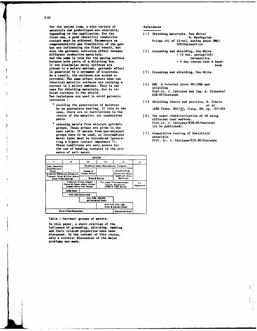
5-10
For the second item, a wide variety of Referencesmaterials and gaskettypes are available,depending on the application. For the [1] Shielding materials. Don White/first one, a good (metallic) conductive H. Hardiguiancontact must be achieved. Parameters as Volume III of 12-vol. series about ENC/compressibility and flexibility of the gas- ICT/Gainesvilleket are influencing the final result, butalso the galvanic corrosion effect between [2] Grounding and shielding, Don Whitedifferent conductive materials. - 12 vol. series/ICT/And the same is true for the mating surface Gainesvillebetween both parts of a shielding box. - 4 day course text & hand-If two dissimilar metal surfaces are bookplaced in a moiety ambient, galvanic effectis generated by a movement of electrons. [3] Grounding and shielding, Don WhiteAs a result, the surfaces are eroded orcorroded. The same effect occurs when twoidentical metallic surfaces are carrying a [4) EMC a tutorial about EHI/EMS and
current in a moisty ambient. This is the sieldingcase for shielding materials, due to in- shieldingduced currents in the shield. Prof.ir. J. Catrysse and ing. A. Sinnaeve/
Two techniques are used to avoid galvanic KIH.WV/Oostende
corrosion : [5] Shielding theory and practice, R. Schulzo avoiding the penetration of moisture et al.
by an appropiate sealing. If this is the IEEE Trans. EHC/30, 3/aug. 88, pp. 187-201case, there are no restriations in thechoice of the metallic (or conductive) [6] The exact characterization of SE usingparts. different test methods.
* choosing metals from adjacent galvanic Prof.ir. J. Catrysse/KIH.WV/Oostende
groups. These groups are given in the (to be published).
next table. If metals from non-adjacentgroups have to be used, an intermediate [ 7 ] Comparative tasting of Bekishieldmetal layer must be introduced (genera- materials.ting a higher contact impedance !). Prof. ir. J. Catrysse/KIH.WV/Oostende
These conditions are very severe forthe use of banding contacts in the pre-sence of salt water.
GROUP
isIII IV V VIG:1. Pl ,:m Chromoum plate. Molybdenum. Tungsten
alloys coop..' & fAluminum &IG'aolt,,,. Rhod,usn. Pallado. , Co-p..' Alloys Al.mnun Alloys.Titanium. Silor & Suin alloys Cadmium. Zinc.
Silnet.lilled coatmng Stas, & Bronze sorylhomTis iom, Nickel, cob , Tin. Lead. TinlLad oldrsl Tin.
Niqcke & coke lt lloyi. Nickell I0dcm. Aluminum MagnasontCoooer alloys linc. Moaell (2000 & 7000 Seoeas
A2S8 Stet
AISI 300 SeIral Stool431, 440. AM3550pH hwdoned Steel,
AISI 410.416. 420.Alloy & Carbson Steels
Silver-1lfle Glaatolvee, Oelnanized Steel
Table : Galvanic groups of metals.
In this paper, a short overview of theinfluence of grounding, shielding, bondingand their related properties have beendiscussed. In the context of this course,only a tutorial discussion of the majorproblems was made.

6-1
A REVIEW OF THE NATO D4C ANALYSIS PROGRAMME ANDRELATED EUROPEAN COMMUNITY DEVELOPMENTS
by
T.K. FitzSimonsformer Head, DMC Section
Allied Radio Frequency AgencyNATO HQ, Brussels
iumay1.3 National EMC progras already existedat that time but did not meet NATO' s needs.
In support of the International Military The national progranmes were, and still are,Staff and the Allied Radio Frequency Agency, principally invoIved with platform, cosite orthere has been a NATO E4C Analysis Programme intra-system EC. A new organisation wassince 1973. Early work involved needed to tackle problems havingcompatibility of fixed frequency systems and multinational or NATO-wide aspects. The aimsthe development of frequency assignment of the NATO EC programme have hardly changedmodels. More recently the work his involved from its inception but the scope of theproblems associated with the compatibility of programme is much wider. Today itfrequency hopping systems and their increasingly contributes to the work of othermanagement. Increasing competition for NATO agencies, committees and groups such aslimited spectrum space by both military the Allied Tactical Communications Agencysystems themselves and also by civil systems (ATCA), Sub-Group 5 on the NATOcoupled with the need for more dynamic Identification System (NIS), the Allied Navalfrequency management in the battlefield poses Communications Agency (ANCA) and the NATOmany compatibility interests for the future. Ccmmiications and Information Systems AgencyMilitary and civil DIC interests are also (NACISA).becoming more inter-related because ofEuropean Comaunity decisions concerning 1.4 To fulfil the original objective of thetelecommunications and electronic devices. programme, the Military Committee invested
this responsibility with ARFA. In setting upthe programme, NATO was faced with the choice
1. acksround to the NATO EMC Analysis of whether to carry out most or all of theProsramme work in-house with a substantial team of
wide-ranging skills or whether to establish a1.1 The NATO E4C Analysis (NEMCA) Programne small team which would contract out the mostis now well established although of fairly detailed, calculation-intensive work torecent origin. The Military Committee of existing specialised EMC groups in industryNATO agreed the need for a NZCA Programme in or national defence organisations. The1971 (ref 1) and the first posts were filled latter course was chosen and the E4C Sectionin 1973. The need for an E&C analysis of ARFA is a team of only four people with aactivity arose out of the functions and modest budget which enables them toresponsibilities of the Allied Radio commission studies requiring larger orFrequency Agency (ARFA). This is one of five different resources.Telecommunications agencies located at NATOHQ within the CIS Division of theInternational Military Staff (figure 1). 2. Scope of the NATO EMC AnalysisAmong the tasks of ARFA is the coordination Programmeof Frequency Supportability Applications fornew military systems and equipments to be 2.1 In giving terms of reference for the newdeployed in NATO Europe and the day-to-day activity, the Military Committee in MC 177,management of the band 225-400 MHz which is a recognised three different categories of 4Cmilitary frequencyband in all the European assessment:NATO countries. The frequency supportabilityUAipcation process consists of establishing a. EguiMent EC aimed at ensuringwhether the new system or equiement is itat all components and modulessuitable for operation in the frequency band within an electronic equipmentor bands for which application is made. will function properly withoutAgreement by the nations of ARFA implies causing interference to otherthat, subsequently, efforts will be made to elements of the same equipment.find allotments or assignments of frequencies This is a nationalto allow the newcomer to operate. responsibility.
1.2 ARIA which had been established in b. Intra-Svetem EMC addresses the1951, founa in the late 1960. and early electromagnetic compatibility1970s, that increasing densities of within large installations orcommunications equipments, the emergence of platforms (ships, aircraft) withnew types of coding and modulation schemes the objective to reduceand the greater mpiasis on system mobility, interference between co-sitedmade it essential to have available D(C systems to an acceptable level soanalysis in support of its work; in that the performance of theseparticular on frequency supportability mystems will not be degraded.applications and also on frequency nis INCresponsibility restsaseigments. either with the national
authorities or, if the system is
f. J
6-2
procured by NATO with the NATO on-many) impact. It is rare for a particularagency responsibie for system to have exclusive use of a band ofprocurement. In the latter case frequencies or even of a number of channelssome of the work may be performed (allotment) and given the dynamic characterunder the NEMCA Programme. The of tactical military systems, absoluteNATO Airborne Early Warning compatibility is not possible. Many of theSystem is an example. pro ects within the NECA Programme have
involved system-to-system analyses aimed atc. Environmental EMC takes into finding whether operating conditions can be
account the actual deployment of established underwhich a tolerable level ofa system under operatlonal interference is not exceeded .and which do notconditions including unduly restrict the military mission. Withinteroperability Electronic different systems operating in the sameWarfare and flexibility frequency band and having to share limitedrequirements and has to ensure frequency resources, the requiredthat both the system under compatibility can be achieved by equipmentconsideration and other existing and system design and also by systemand planned systems sharing the management. Within the scope of systemsame frequency subband(s) in the management, use or access to the radiosame geographical area will be frequency spectrum contributesinthe form ofable to per form their functionscompatibly. The procuring nationor RATO agency is required to frequency separationdetermine the conditions under distance separationwhich a new system can be time separa tion.compatibly deployed. Alsoincluded In environmental EMC In theory at least, one could addconsiderations are aspects such polarisation decoupling but in the frequencyas the equipment mix in a band, bands where the need is greatest, below 1frequency assignment or allotment GHz, propagation characteristics and thestrategies and other questions of deployment constraints of the tactical systemthis type, which are not result in a benefit that is not sufficientlyassociated with procurement of a consistent to make this a practical option.specific system, In these casesa general policy will be applied, Although spreading codes and frequencywhereby the administration (or hoppingsequences are used in order to avoidagency, or command) with the detection and jamming, their characteristicsauthority to decide on these can also be managed so as to achieve EMCquestions is inherently within systems. Indeed the assignment ofresponsible for dealing with the hop-set sequences (or net numbers) isEMC analysis implications of such analogous to the assignment of singledecisions. It is work within frequencies.this category which forms thebulk of the NATO EKC Analysis 3.2 Assessing how well the management ofProgramme. these parameters can achieve the required
compatibility of systems in a battlefield2.2 Although the NATO EMC Programme is environment, involves complicated analysesconcerned mainly with environmental E4C and which necessarily include data on deploymentcommunication systems studies, NATO involves scenarios, frequency assignments, hop-setitself in certain cases with equipment EMC. characteristics, equipment parameters,For example, the NATO Military A ency for interference thresholds and propagationStandardisation (MAS) has pubis ed the statistics or models. Complications arisefollowing series of NATO Standardisation from establishink the deployment scenarios,Agreements (STANAGs) on the EMC of aircraft which sometimes involves both red and bluesystems and equipments: forces, and from interpreting the analysis
results in operational terms. However, asSTANAG 3456AE Aircraft Electrical System will be described, many system-to-system D4C
Characteristics analyses performed under the NDECA ProgrammeSTANAG 3457AE Ground Electrical Power have gained acceptance and resulted in, for
Supplies for Aircraft exampe, the basis for management of the 225-STANAG 3516ASEC for Aircraft Electrical 400 Hz band, the selection of hop-sets for
and Electronic Equipment the EW resistant communications systems HAVESTANAG 3614 EKC of Aircraft Systems. QUICK and SATURN, decisions on the use of low
power (unlicensed) devices in militaryWork is in progress in SWGlO of the CNAD frequency bands and have influenced strongly(Conference of National Armaments Directors) the strategies for frequency management ofto develop a STANAG on inter-ship E4C. the VHF (30-88 MHz) band which must
accommodate Combat Net Radio and SingleChannel Radio Access systems.3. Envir~,nmental 34C3.3 The problems of environmental EMC arise
3.1 Within the NUECA Programme the narticularly with operations in the militaryenvironmental EC assessment sometimes frequency bands below about 5 GHz (figure 2)involves establishing by analysis or bench and most of all the so-called VHF and UHFtest, the effect of one equipment on another bands, 30-88 MHz and 225-400 MHz. This is a(one-on-one) but this is usually the first consequence of these bands being the moststep in assessing the system on system (many- suitable for tactical battlefield systems by
fr
6-3
virtue of propagation and antenna They are digital systems requiring betweencharacteristics. Much of the effort of the 0.5 and 1.5 MHz of bandwidth for each pointNEKCA Programme has been and continues to be to point connection.focussed on these two frequency bands. Tactical Satellite Systems. UHF satellite3.4 For many years the main military use of systems operate in sub-bands of the 225-400the 30-88 MHz band has been for Combat Net MHz band and use fixed and mobile groundRadio (CNR). These are highly mobile systems stations including aircraft and ships.used in a tactical area in the form of Channel widths vary from 5kHz to 500 kHz.vehicle-mounted and man-pack units. The bandhas always been over-subscribed in terms of Navy Communications. These are for the mostthe number of different nets fielded and part single channel systems having equipmenthence the number of fixed frequency characteristics similar to AIG/ systems.assignments requested. Compatible operation Like the air force systems they are nowhas been achieved to some extent by judicious equipped to operate in both Lixed frequencyfrequency management at both the allotment and frequency hopping modes.and assignment levels. New problems ofcompatibility have arisen recently by the These systems and others must all share theintroduction of digital systems and the EMenvironment compatibly through having tofielding of automatic channel selection (ACS) share the same spectrum and sometimes theand frequency hopping systems. In addition, same channels.the band now has to accommodate SingleChannel Radio Access (SCRA) systems from somenations having the same range of parameters. 4. Example Projects within the NEMCAAll CNR and SCRA systems are very dynamic in Programmeterms of their location and their temporaldemand for communications access. Both CNR 4.1 In this section a few of the proiects andand SCRA can operate in the same area of the activities, both past and present, within thebattlefield ana may at any time be within co- NEMCA Programme will be reviewed. They havechannel and adjacent channel interference been selected to illustrate the range ofdistance of similar (but utfortunately not system E4C problems encountered and how theyidentical) systems of Allied nations. have been tackled.
3.5 The frequency band 225-400 MHz, with 4.2 Introduction of frequency hoppingminor sub-band exceptions, has been agreed to systems (NEMCA Project 4).be available for exclusi-re military use inNATO Europe both in peactime and in wartime. A project was established in the early 1980sThis fact alone would be enough to ensure to investigate the effect of introducingthat it is heavily used in terms of systems frequency hopping systems into theand assignments. Additionally, of course, battlefield zone. The early part of thethis range of frequencies is attractive in project was aimed at investigatingterms of both single channel and multi- interference mechanisms and establishing thechannel systems and it is the highest threshold levels with other systems in bothavailable frequency band for tactical systems the VHF and UHF bands. Much ofthis work wasw)-.ere links of reasonable length can be performed through study contracts let byestablished without necessarily having radio ARFA. These studies analysed theline-of-sight. This band is used therefore interference at the equipment-to-equipmentto support a wide range of narrow and wide level for various types of victim receiverband systems which are, for the most part, and for a range of hop-rates for thedestined to be operated in the tactical frequency hopping system. In this first partregion of the battlefield (including sea and of the study the interference to singleair space) and which must be capable either channel A/G/A systems, conventional CNR,of rapid deployment or mobile operation radio relay systems and domestic television(figure 3). All the principal systems was investigated. These one-on-one resultsoperating in this band listed below have been were used to assess the impact of hoppers oninvolved in the various EMC analysis projects the UHF and VHF bands.within the NEMCA Progranune.
The next phase :f the VHF band study extendedAirjGroundlAir JA/G/A). Although some the work to the system level (ref 2). Forni tary aircraft can use the VF band almost this it was necessary to describe a range ofall communications between aircraft and operational scenarios involving a singlebetween ground stations and aircraft must be Corps area two and three adjacent Alliedassigned in the range 225-400 MHz. Some 8500 Corps and finally that of two Allied Corpsassigrments are presently made. Ground and an enemy Corps in which the VHF band wasstations may include high-power amplifiers to also used for tactical communications. Theovercome jamming to the aircraft and may have study produced very valuable though arguablymore than 30 assignments. The single channel not surprising results. It con irmed theA/G/A communications include amplitude overcrowding of the VHF band that users hadmodulated clear voice transmissions as well long complained about and the likelihood ofas encrypted voice and data. Fixed frequency interference even between conventional fixedoperation can take place in the same area and frequency systems. The value of thetimeframe as slow and fast frequency hopping. confirmation was that it focussed attention
on the problems of frequency management ofthe VHF band and all subsequent discussions
Radio Relay. Trunked radio relay systems on its use, including the introduction of newprovide the backbone communications for the equipment designs have been influenced byautomatic switched tactical area systems. NECA Project . It must be borne in mind

6-4
that by the mid-1980s, large scale exercises Tactical Spectrum Management System (TSMS).had become less and less frequent and in anycase it is difficult to obtain field data for 4.4 Current VHF Band Study (NMCA Project 7)several Corps under normal exerciseconditions. Current NEMCA activities in the VHF band are
covered under NEICA Project 7 which is aThe study also showed that for an over- follow-on to Project 4. It is a studysuscribed frequency band, operations in a requested by the Allied Tacticalcombat environment could be improved by CNR Communications Agency and is an attempt toor SCRA systems using Automatic Channel assess the effect of the deployment of AlliedSelection up to a certain level of channel Electronic Warfare (EW) assets, e.g. jamners,utilisation. The automatic channel selection on VHF band operation. The study takes asexploits any temporal, spatial and spectrum its baseline, the scenarios and results ofopportunities until prevented by local or NE4CA Pro ect 4 and adds an EW scenariowiaespread saturation. It represents a involvingland-based and airborne jammers.dynamic refinement of the frequency The results may well help to indicate in whatassignment process. ways we need to extend ahd improve frequency
management in the battlefield to achieve anConcerning the fr,--ency hipping systems, the acceptable level of compatible operation ofstudy showed nat 'meaured in terms of Allied communications and EW.system-wide interference, frequency hoppingsystems would cause interference to more 4.5 Introduction of Frequency Hoppers in thereceivers in an over-subscribed situation UHF Bandwhere the hoppers could not be givenexclusive channels. However the nature of Using the results of the first phase of ND4CAthe interference produced by frequency Project 4, an evaluation on the impact ofhoppers is different and it can be said that introduciiig the slow frequency ho pping systemthey are more democratic in their manner of HAVE QUICK into the 225-400 MHz band wasinterference. In a fixed frequency performed. The initial operation for HAVEenvironment, where co-channel, adjacent UICK was for Air/Ground/Air and Air/Airchannel or intermodulation interference Communications particularly in roles ofoccurs, it will affect a limited number of direct support to air defence. The one-on-victims, but it may affect them severely and one results obtained for potential UHF bandit will be persistent. Frequency hopping victim receivers showed that, given the orderinterferers will interfere with more victims of the hop-set size provided by the 225-400but only for the time of a dwell and MHz band, and the re-visit and dwell times oftherefore depending on the hop-rate and dwell the system, HAVE QUICK could share to antime and the number of frequency hopping nets acceptable degree of compatibility, theit mayibe possible to achieve a sort of frequencies assigned to other fixed frequencycompatibility where there are more victims Air/Ground/Air systems. Radio relay anWdetecting interference but fewer suffering to Tactical Satellite systems were judged to bean intolerable extent, not suitable for sharing. The results of
this evaluation were then used to establishOperational judgements may still have to be the size of the hop-set and select themade on the protection of long links or of candidate hop-set frequencies for HAVE QUICK.vitally important nets. With conventionalfixed frequency sy stems, this was built into 4.6 Hop-set Management for Electromagneticthe frequency assignment process thereby Compatibilityavoiding any possibility of co-channel oradjacent channel interference in those Given that a hop-set must be of finite size,particular cases. it must be used in such a way that links or
nets can be operated independently of oneThey can still be protected from frequency another without interference within thehoppers by excluding certain frequencies from hopping system. The obvious way to do this,ho p-sets or the frequencies interrogated by in those cases where it is possible, is byACS systems but there is an obvious risk of establishing an orthogonal mode of operation.giving away information to the enemy and This means that all the hop-set sequencesthere is in any case a limit to the number of switch frequency at the same instant andcandidate frequencies that can be denied to dwell for the same period in such a mannerhopping or ACS systems without in turn that at any moment, a particular frequency isimpairing their operation. only being used by one of the ho p-set
sequences (or nets as they have become4.3 A very significant outcome of NEMCA known). If for example, there are 100Project 4 was the drafting of a Military frequencies in a hop-set, there will be anCommittee document by ATCA aimed at improving upper limit of 100 orthogonal nets that canthe situatior by management means. MC 297 be obtained whether or not the nets hoDref 3) outlines the need for improved means through the 3et in the same sequence. The
for assigning VHF radio frequencies in the hop-set sequences, or nets, must be assignedtacti(al battlefield area. This need, in a calculated manner in much the same wayidentified by the Military Cosmittee, was as fixed frequencies to avoid interference.endorsed by the Secretary General of NATO and Even if only orthogonal hop-set sequences areresulted in the establishment of Project allowed, interference can occur on adjacentGroup 8 under the TSGCEE. PG8 has decided channels (particularly at co-sites) and itthat the need for improved frequency could occur on co-channels if the number ofmanagement tools extends beyond CNR and the nets to be assigned is greater than theVHF band and has detailed a programme of work available number of orthogonal sequences.which will lead to the development of a

6-5
Work was performed under the NEMCA Programme data in order to provide validation or toin 1988-1989 to establish the rules to be propose further model improvements. Anotherapplied to the assignment of net numbers (a important development in this work is then"mber which effectively identifies the NATOStaff Target drafted by SWGl0 for an'341sequency) for the HAVE QUICK system in NATO PredictionModel and Data Basel. This wouldEurope. These rules are now incorporated in build on the experience of NATCAP to producethe SHAPE Standard Operating Procedure (SOP) a tool to predict interference involving(ref 4) and the same algorithm will probably communications including Tactical Satellitebe the basis for the net assignment rules systems, as well as radar. It is intendedwhich will be established for the SATURN that the model will be developed in a formsy stem which will gradually succeed HAVE which will support detailed frequencyQUICK over the next few years. assignment planning and be available in a
suitable form for use at sea.Adjacent channel compatibility withinfrequency hopping systems can be achieved 4.8 Post-2000 Communicationseither by dividing the total number offrequencies available into a number of As well as dealing with EMC problems ofsmaller hop-sets which can then be used current or emerging systems the NEHCAindependently or by using all frequencies Programme includes work on future systemsavailable but arranging hop-set sequences that are still very much in the conceptualsuch that, throughout the ihole length of the stage. Staff participate in the meetings ofpseudo-random sequence, there will always be Project Group 6 of the Tri-Service Group ona minimum instantaneous frequency separation Communications and Electronic Equipmentbetween certain hop-set sequences. Within a (TSGCEE). PG6 is studying the requirementscompletly orthogonal system there will be no for tactical communications in the landpossibility of co-channel interference if no combat zone, post-2000. ARFA has contributednet number is assigned twice and that need to their work bypreparing a qualitativenot occu until the number of nets required forecast of the Eeenvironment in which theexceed the maximum available for that hop-set post-2000 systems will have to operate (refsize. Even then, compatible operation can be 9). Factors which ARFA deemed will beachieved by re-assigning -iet numbers when the important influences on the environment forinterference distance is exceeded. Assigning tactical communications included:net numbers, or hop-set sequences, istherefore analogous to assignment of fixed - Spectrum availability. Thefrequencies. currently available military
spectrum is described in the NATO4.7 NAVY EMCIEMI Joint Frequency Agreement.
Tactical bands are available atThe EMC Section of ARFA has, for more than HF, VHF or UHF in peace and warfour years now, provided the technical and can be exclusive or sharedsupport to Special Working Group 10 which with civil users. In the post-reports to the NATO Naval Armaments Group 2000 period the amount available(NNAG). The work involves the problem of for military use may beintership EMC/EMI arising out of the decreased. The range 500-3000formation of multi-nation task farces. The MHz particularly is expected toclose formation of different ships having come under pressure from civildifferent equipments produced a special interests at the Worldproblem for which national management Administrative Radio Conferenceprogrammes were not equipped. ARFA assisted in 1992. The new climate ofin the development of an interference opinion in Western and Easternprediction model called NATCAP (NATO Europe may make future defencesElectromagnetic Compatibility Analysis of military spectrum moreProgramme). This was based on an earlier US difficult. In summary, formodel called EMCAP. The first version of peacetime and wartime operations,NATCAP dealt only with radar-radar the spectrum available will notinterference. It uses data on the antenna be greater, it may well be less.radiation patters, the radar transmitterspectrum and the victim receiver response to Many present systems will stillprovide a prediction of the probability of be operational beyond 2000. Theinterference. Observations were made by current lifetime of about 20several national navies during the exercises years for new systems may be'NORTHERN WEDDING 861 and 'DISPLAY extended due to the goodDETERMINATION 871 to validate predictions reliability of modern equipments.made by the model. After NORTHERN WEDDING86, the model's propagation module was The post-2000 systems willmodified under a contract awarded by ARFA. introduce new hop-rates and otherThis now allows for the optional use of a ECM tesistance features. Thesenear-water path loss calculation which was may conflict with good EMC, whichbased on data obtained through ARFA in principle is most easilyparticipation in AGAID Working Group 02 achieved with 'like systems', fordealing with Near Water Propagation (ref 5). which better management rules canbe developed.Several NATO nations are now using the NATCAPmodel for their own purposes. The most The new generation of ECHrecent ARIA contribution to SWGO has been to resistant communication systemsobtain national predictions and results of will generate their own MCtziala, and to make an analysis of the entire problems for which solutions have
, T . .... .

6-6
et to be found. For example as Single European Act, (which is a modificationhe density of deployment of of the Treaty of Rome) taken to ensure that
frequency hopping equipments at the movement of goods across EC internalco-sites increases boundaries cannot be thwarted by barriers,intermodulation will become a and this includes technical specifications.problem. The solution is not as It is clear from the IC directive that thestraightforward as for fixed legislation and the standards and testfrequency systems. Another methods will apply to a wide range ofexample is that just as finite electrical and eiectronic appliances. Therepropagation time means that a is the notable exemption given to the radiofollower jammer cannot jam a equipment used by radio amateurs but evensystem hopping at very last then only if the equipment is not availablerates, it also means that the commercially. The direction includes thefrequency hopping system becomes following list of products as an illustrationnon-orthogonal and co-channel of what will be covered:interference can occur.
a. domestic radio and television receiversThe ARFA contribution to PG6 concluded thatfor the post-2000 systems to achieve a high b. industrial manufacturing equipmentdegree of compatibility they must be designedto: c. mobile radio equipment
a. operate in a shared spectrum d. mobile radio and commercial radio-environment, and telephone equipment
b. avoid co-site interference, e. medical and scientific apparatusincluding image, harmonic andintermodulation. f. information technology equipment
Their development must go hand-in-hand with g. domestic appliances and householdthe development of better operational and electronic equipmentfrequency spectrum management techniques.
h. aeronautical and marine radio apparatus4.9 Other current and forthcoming taskswithin the NATO EMC analysis programme i. educational electronic equipmentinvolve the EMC of Tactical SatelliteSystems, the NATO Identification System (NIS) j. telecommunications networks andand associated national EMC studies, and the apparatusAir Command and Control System (ACCS) whichwill be the successor to the NATO Air Defence k. radio and television broadcastGround Environment (NADGE). transmitters
1. lights and fluorescent lamps.5. The European Community EMC Directiveand its Possible Impact on Military The directive also states that thesecommunications Eauipments equipments and appliances, as well as being
compatible by virtue of their emissions, must5.1 The first part of this lecture dealt be constructed in such a way as to have anwith a rather specific area of activity. The adequate level of electromagnetic immunity.previous lectures concerned wide-rangingtopics. In this part of the lecture, EMC 5.4 As well as the national legislativedevelopments in the European Community (EC) preparations, work has already started on thewill be reviewed and it will be seen that development of specifications and testthese developments will have a bearing on standards. There exists an organisationalmost all the EKC issues dealt with in this called CENELEC (European Committee forlecture series. They even have an impact Electrotechnical Standardisation)whichactsbeyond the European Community area. on behalf of the European Commission to deal
with the technical issues. It is a non-5.2 The EC published a Council Directive on profit making organisation set up underEMC in the Official Journal of the European Belgian Law and is composed of a SecretariatCommunities on 23 May 1989 (ref 7). It had and the National Electrotechnical Committeesbeen approved by the Council on 3 May 1989. of 18 countries in Western Europe. The 18The directive is a document which is binding countries are the IC countries plus the EFTAon governments, and member states of the EC (European Free Trade Area) countries. In theare required to adopt legislation to context of the composition of CENELEC it isimplement the directive by 1 July 1991. This im ortant to remember that not only are notis done through national legislation. The alf the EC countries in NATO but not all NATOnecessary 1egislation to apply the provisions countries are in either the EC or EFTAof the directive must, according to the (figure 4). CENELEC was given the legalpresent timetable, be applicable by right to set reference European standards on1 January 1992. behalf of the EC as long ago as 1983 (EC
Directive 83/189). In the matter of EKC,5.3 The basic reason for the EC action is CENELEC tried to do this first byto support the internal market; in other harmonisation of existing national andwords to permit the free movement of goods. international standards. This could not beThe EC directive on EC is just one or a made to work and in order to implement the SClarge number of measures consequent on the directive, work is now in progress to develop
I

6-7
common enforceable standards. As soon as civil users. Furthermore, some equipmentsCDIELIC started this work, a 'standstill" on my be developed originally with the militarynational IC standards was imposed. This is as the intended user but then became morestandard CEINLEC procedure and it means that widely available (e.g. night vision devices).no new national standards can be developed No exemption can be obtained on the basis ofand no existing ones modified.
the frequency bands of operation. CENELECThe work is being done by two technical will app y their standards to all frequencycommittees composed of national bands as they are described in the TUrepresentativest Regulations, whether they are exclusively
civil, shared military and civil, orTCllO on DC exclusively military.
For most military electrical and electronicTCll0 is charged to set up comprehensive equipment, meeting the CENELEC standardsgeneric standards covering the aspects of would not be technically onerous. Mostelectromagnetic emission and imuunity in line military procurement specifications includewith the directive, taking into account ENCstandards. National ones such as MILSTAMexisting national and international 461 (USA) and DEF-STAN 59-41 (UK) arestandards. It will also describe the probably more rigorous inmost respects thancharacteristics of typical SK environment those that will emerge from CENELEC. In anylocations for apparatus, which can be case the CENELEC standards will be based oncorrelated with test methods. It will national inputs to the CENELEC comuittees. Aspecify recommended emission limits and problem may arise for organisations such asiimnity levels. The prepared standards will Defence Ministries, in that, because of theircontain definitions, reqiremnts test own specialised EKC requirements, it may bemethods, test instrumentation and conformance necessary for their equipments to becriteria, compliant with both their own and the EC
standards. These considerations indicate theSCll0A is charged to consider the desirability of having national defence andharmonisation of product related documents NATO inputs to the technical committees.and to participate in the preparation of the Even if military equipments themselves arededicated product standards as requested by not subsequently covered by the legislation,TCll0. operation in radio frequency bands shared
with civil users could be affected.5.5 From the list of apparatus and Particularly in the area of imunnityappliances and the scope of the CENELEC (susceptibility) from emissions, there my becommittees it is clear that, even allowing a need to influence the standards since thefor some lack of definition most electrical design approach for the military and civiland electronic apparatus will be affected by equipments is very different because of theirthe directive as well as much of the existing intended working environments. Even for4C standards and D4C tasking activities. To operation in exclusive military frequency
be covered by the legislation, it is simply binds NATO and national defence inputs to thenecessary that the product is to be made discussions may be needed in order tocommercially available in the SC or EFTA influence the limits on out-of-band emissionscountries whether made in those countries or that could be radiated by devices using theoutside. CENELEC's work is well underwa . adjacent band of frequencies.The first two generic standards and the lirstfive product oriented standards had, by 5.7 Recent experience in theUShas shown theAugust 1990, been distributed for comment. need for vigilance concerning the in-band andThe CENELEC Secretariat is confident that out-of-band emissions of so-called "Non-most of the generic standards will have been licensed Devices'. Many of these correspondpublished by the end of 1992. to apparatus referred to in Europe as Low
Power Devices'. The American and European5.6 The important issue for NATO and also descriptions cover a wide range of devicesfor national defence authorities is whether such as garage and car door openers, radiothe directive and hence the CiNELEC standards controlled toys, baby alarms and cordlesswill appply to military equipment. The issue telephones. In the US, standards for the in-is complcated and has caused much discussion band characteristics have been establishedsince the publication of the directive, but not for out-of-band emissions. Even theThere is in fact an exemption for military in-band emission levels can be high and doequipment contained within the Treaty of Rome not correspond to everyone's definition oftoself in Article 223. This makes reference 'Low Power*. Under the EC directive, these
to munitions of war and thus clearly exempts appliances would need to comply with theweapons. It is not clear whether it was CEINLIC standards but as in the US,intended to exempt military equipment at the individual radio licenses would not betime of the original Treaty. A case can be needed.arfued for exemption where apparatus is notoffered for sale on the open market. 5.8 Many devices are already available inCertainly there is still a range of equipment Europe and it must be expected that their useand apparatus, of a non-weapons nature, that could become as widespread as in the US,is procured by the military and is not where 13 million garage door openers havecosmercially available. However, in the been sold. In recent years several of thecategory of information technology and to a European national authorities have receivedlesser extent telecommnications, the requests for approval of Low Power Devicesmilitary usae equipments that are the same or anQ these inclded some for o ration in thesimilar to those available cosmercially for military band 225-400MHz. This band is not
t I ..... ... .
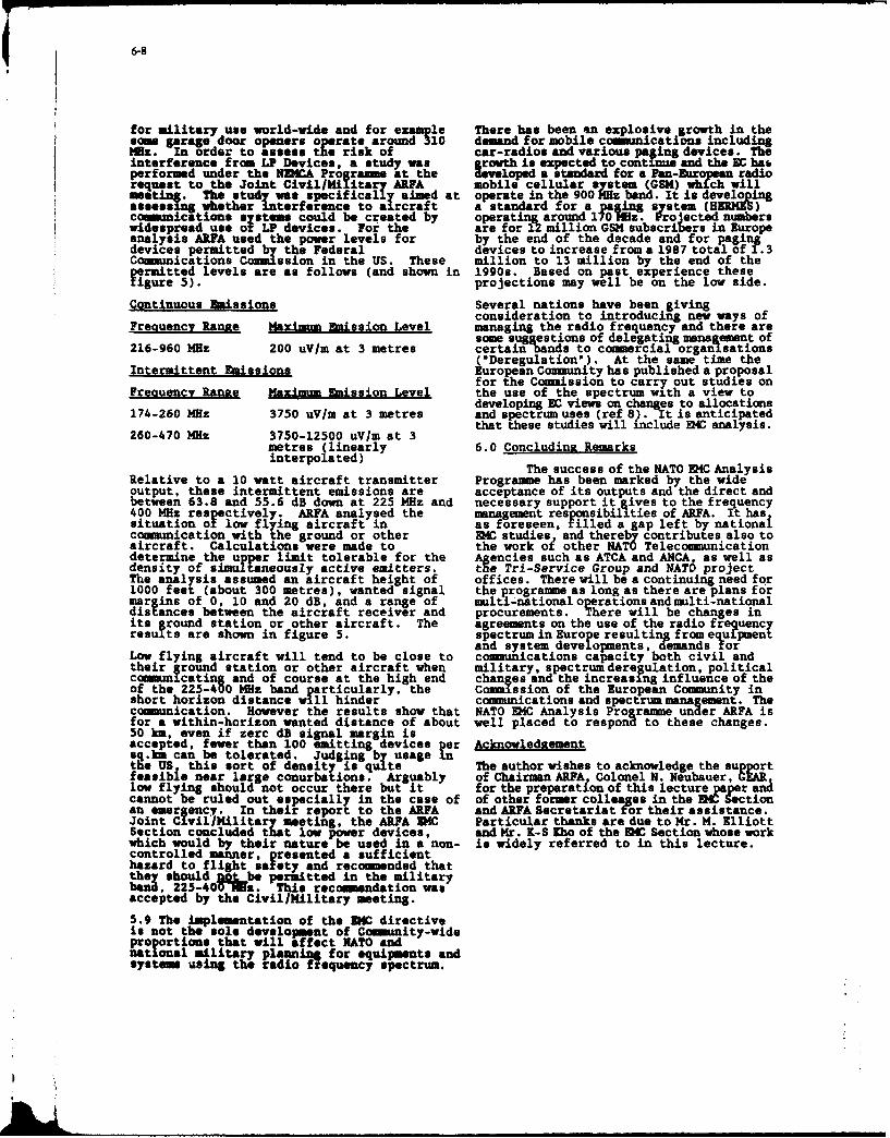
6-8
for militaryuse world-wide and for example There has been an explosive growth in thesore garage door openers operate around 310 demand for mobile communications including14z. In order to assess the risk of car-radios and various paging devices. Theinterference from LP Devices, a study was growth is expected to continue and the EC hasperformed under the MU Prorame at the developed a standard for a Pan-European radiorequest to the Joint Civil/Military ARFA mobile cellular system (GSM) which willmest . The stuy aecifica-l aimed at operate in the 900 Hz band. It is developingaesas: whether interference to aircraft a standard for a _ag in stem (H 5)coounications systems could be created by operating around 170Ml z. Projected numberswidespread use of LP devices. For the are for 12 million GSM subscribers in Europeanalysis ARFA used the power levels for by the end of the decade and for pagingdevices permitted by the Federal devices to increase from a 1987 total of?. 3Ccm-nications Comision in the US. These million to 13 million by the end of theermitted levels are as follows (and shown in 1990s. Based on past experience themegure 5). projections may well be on the low side.
Continuous Emissions Several nations have been givingconsideration to introducing new ways of
Frequency Range Maximu Emission Level managing the radio frequency and there aresome suggestions of delegating management of
216-960 MHz 200 uV/m at 3 metres certain bands to commercial organisations('Deregulation'). At the same time the
Intermittent Eaissions European Community has published a proposalfor the Coamission to carry out studies on
Freauencv Ranne Maximum Emission Level the use of the spectrum with a view todeveloping EC views on changes to allocations
174-260 MHz 3750 uV/m at 3 metres and spectrum uses (ref 8). It is anticipatedthat these studies will include EKC analysis.260-470 MHz 3750-12500 uV/m at 3
metres (linearly 6.0 Concluding Remarksinterpolated)
The success of the NATO EMC AnalysisRelative to a 10 watt aircraft transmitter Programme has been marked by the wideoutput, these intermittent emissions are acceptance of its outputs and the direct andbetween 63.8 and 55.6 dB down at 225 MHz and necessary support it gives to the frequency400 MHz respectively. ARFA analysed the management responsibilities of ARFA. It hassituation of low flying aircraft in as foreseen, filled a gap left by nationalcommunication with the ground or other EW studies, and thereby contributes also toaircraft. Calculations were made to the work o? other NATO Telecommunicationdetermine the upper limit tolerable for the Agencies such as ATCA and ANCA, as well asdensity of simultaneously active emitters. the Tri-Service Group and NATO projectThe analysis assumed an aircraft height of offices. There will be a continuing need for1000 feet (about 300 metres), wanted signal the programme as long as there are plans formargins of 0, 10 and 20 dB, and a range of multi-national operations and multi-nationaldie ances between the aircraft receiver and procurements. There will be changes inits ground station or other aircraft. The agreements on the use of the radio frequencyresults are shown in figure 5. spectrum in Europe resulting from equipment
and system developments, demands forLow flying aircraft will tend to be close to commncations capacity both civil andtheir groind station or other aircraft when military, spectrum deregulation, politicalcommunicating and of course at the high end changes and the increasing influence of theof the 225-400 MHz band particularly, the Cosion of the European Community inshort horizon distance will hinder comunications and spectrum management. Thecommunication. However the results show that NATO EKC Analysis Programme under ARFA isfor a within-horizon wanted distance of about well placed to respond to these changes.50 km, even if zerc dB signal margin isaccepted, fewer than 100 emitting devices per Acknowledgementsq.km can be tolerated. Judging by usage inthe US this sort of density is quite The author wishes to acknowledge the supportfeasible near large conurbations. Arguably of Chairman ARFA Colonel N. Neubauer, CEARlow flying should not occur there but it for the preparation of this lecture ar ancannot be ruled out especially in the came of of other former colleages in the DISectionan emergency. In their repor to the ARFA and ARFA Secretariat for their assistance.Joint Civil/Military meeting, the ARFA SC Particular thanks are due to Mr. M. ElliottSection concluded that low power devices, and Mr. K-S Iho of the DC Section whose workwhich would by their nature be used in a non- is widely referred to in this lecture.controlled manner, presented a sufficienthazard to flight safety and reco umended thattnh should'&obo ritted in the military=, 225-40V-Efz. This recommendation wasaccepted by the Civil/Military meting.
5.9 The implementation of the ZC directiveis not the sole development of Community-wideproportions that will affect NATO andnatonal military pl.An ig for equipments andsysteme asLg the adieo frequency spectrum.

*'~ 6-9
References
1. HMG 177 (Final), 30 Aug 712. J.U.H. Smith, M.G. Baile., A.V. Bevan-Computer Simulation Study of Inter-Corps
Electromagnetic Interference in the VHFBand', Systems Designers Ltd. Feb 82
3. HC 297(Final) 26 Jul 85[4. DSfC3JICP(90)4l:WG/5 Serial 14
'Allied Command Europe HAVE QUICKStandard Operating Procedures', 19 Jan90 (and correction DS/C3/ICP(90)107,21 Feb 90)
5. AGAD AR-231
'Near-Water Propagation Effects andHodern System Adaptation', Sep 87
6. M. Elliot 'Interference and TacticalCommunications' ARFA(Z)-WP(90)-0398L-SPA/17719 28 Feb 96
7. Council Directive (89/336/EEC).Official Journal of the EuropeanCommunities, 23 ay 1989
8. Appendix 5 to Annex A to ARFA/S/154Serial 089 "Report of the NDMCA AdvisoryGroup on the Potential IUpact of LowPower Devices in the 225- 00 MHz Band',20 Feb 89
9. EC Council Resolution of 28 Jun 90. Onthe Strengthening of the Europe-WideCoo peration on Radio Frequencies inparticular with regard to services with aPan-European Dimension (Ref 90-C-166/02).
Note:
The NATO references are not contained in openpublications. They may be obtained throughnational representatives to ARFA or ATCAsubject to normal security regulations whereappropriate.
I

6-10
L Director IMS
IMS Secretariat Divisions
Plans and p Logistics and S CommunicationsPolicy and Information
Systems
Agencies
ATCA ACCSA ADSIA ALLA Allied RadioFrequency Agency
NEMCA Plans and OperationsProgramme Policy
Figure I The International Military Staff
BAND SYSTEM DEPLOYMENT
COMBAT NET RADIO MOBILE, FIXEDVHF
RADIO RELAY TRANSPORTABLE
SINGLE CHANNELRADIO ACCESS
UHF A/G/A SYSTEMS MOBILE (FAST)
RADIO RELAY FIXED
JTIDS/MIDS MOBILE (FAST)
SHF RADIO RELAY FIXED
Figure S Miliry Systems 30MHz-5GHz

6-11
SYSTLEMS SHARING TM 225-400 MH1Z. BAND
AIR-GROUND-AIR
AIRCRAFT PWR 20WGROUND PWR 1OOW-3kWBANDWIDTHS 6lcHz-5OkHzANTENNAS: OMNIDIRECTIONALLOCATIONS: GROUND- MOSTLY FIXED
AIR - RANGE > 300M
RADIO R.ELAYI
POWER 20-40WBANDWIDTHS 500kHz-1.5MHzANTENNAS 8-10dB GAINLOCATIONS: SOME FIXED
MOSTLY VARIABLE WITHIN CORPS AREA
NAVY
POWER 20-IO0WBANDWIDTHS 6kHz-5OkHzANTENNAS: OMNIDIRECTIONALLOCATIONS: SHIPS AT SEA AND IN HARBOUR
AIRCRAFT AT SEA AND OVERLANDFigur3
U.S. CENELEC
Belgium DenmarkFrance GermanyGreece Italy IrelandLuxemburgNetherlands Portugal
Figure 4- ParticiRalo EC EFTA ajad CEiELEC
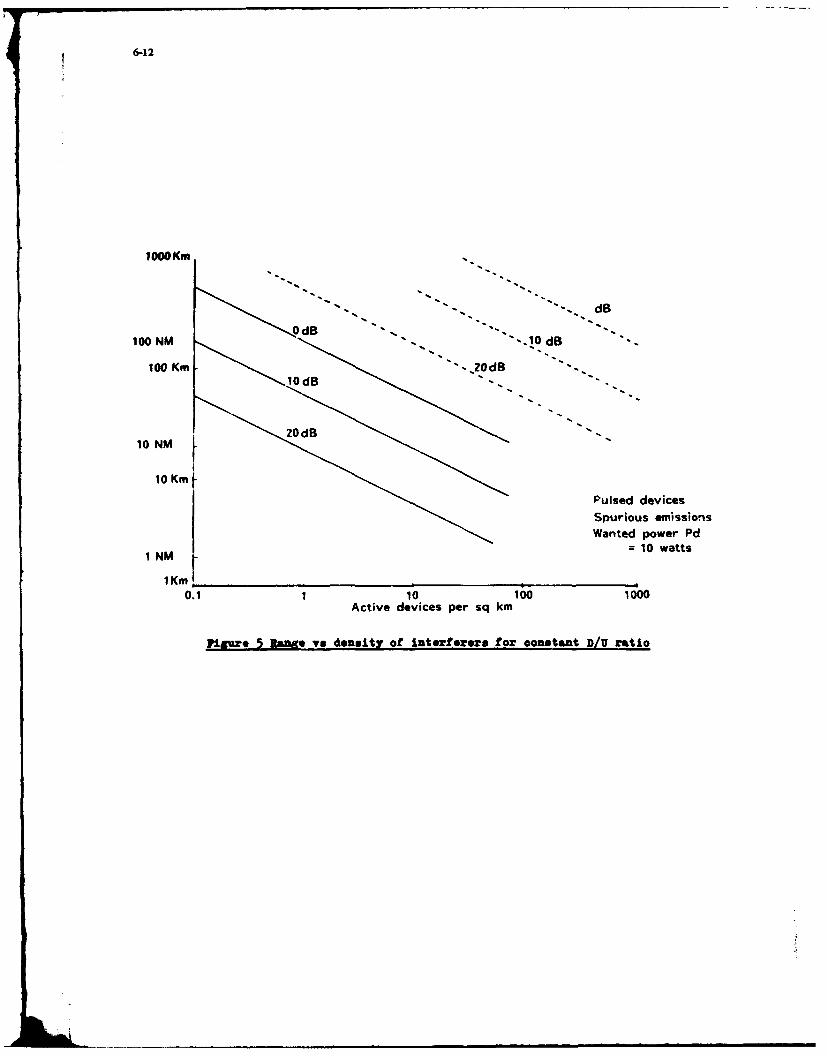
6-12
1000 Km,
S.d B
-. d- d
100 NM10d
10 Km
Pulsed devicesSpurious emissionsWanted power Pd
-10 watts1 NMr
IKm0.1 1 10 100 1000
Active devices per sq km
Fiague 5 Range vs donsity of interfoeres for constant DIV ratio

7-I
SPECTRUM MANAGEMENT AND CONSERVATION
M DarnallHull - Warwick Communications Research Group
Department of Electronic EngineerngUniversity of HullHull HU6 7RX
UK
SUMMARY 1.3 NATO =&==
The lecture fimrennt areviewoft basicconcepts of The NATO operational requirements encompass radio.radio spectrunm utilitaian and de physical mechanisms of radar. control and navigation system of many different types.electromagnetic (EM) wave Propagationofrelevance to radio. fixed and mobile, dispersed over a wide geographical area. andradar, control and navigation systems. A survey of the uses of radiating a large proportion of the available frequency bands.the various bands in the radio frequxecy (RP) spectrum is then Accessrequirements range from continuous to very infrequent.presented. Interactions between die propMgation mechanisms yet all users require a specified grade of service whenever theyintroduced previously and frequency planning requirements choose to access the spectrum. There must also be sufficientare considered, making referesce to dhe precision of available flexibility in the spectrum control procedures to allow newmodelling and prediction procedures; emphasis is given to systems to be introduced without disrupting existing opera-inerernce generation potential. Ataution is then trned to dons. Similarly, flexibility must also be available to cope withequipment and system design features which affect their spec- increased levels of activity in times of emergency, tension ortral occupancy characteristics, incuding RP equipment imper- war.fections, signal design. systm deig and control. and co-siting problems. Finally, the mamer in which the bands of the Of late, there has been an unprecedented expansion in theradio spectrum are allocated and controlled is outlined, and number of civil services exploiting the RF spectrum, particu-areas ofpossible future concernin both NATO and civil opera- larly in the fields of mobile radio and paging; as a result, theretions identified. is increasing pressure on military users to release some of their
exclusive frequency bands in order that these can be made1. INTRODUCTION available for civil purposes. This, in turn, creates a situation in
which military systems must make more efficient use of1.1 3c= of the Lecture reduced spectral allocations.
This lecture is concerned with the use of the radio spec- 1.4 The Electrna ic Conmiatibilily Problemtum by equipments and systems cmpioying 'ungm"dac' piopa-gation, ie energy transfer between distinct geographical loca- The main problems in spectrum management and controltions by the physical mechanisms of radiation and near-field arise from the need to maintain electromagnetic compatibility(reactive) coupling; it does not consider energy transfer via (EMC) between a vast number and variety of systems in situ-"guided"propagation, ie over wires, coaxial cables and optical ations where the degree of natural isolation between thosefibres, except where any energy leakage cannot be assumed to systems is extremely variable. Radio propagation mechanismsbe negligible. Some consideration is given to additional spuri- can usuallyonly be characterised in astatistical manner, hence,ous radiation from bona fide transmitters, and from electronic interaction and interference effects between systems are also ofslstems whose primary function is not to radiate energy. eg a probabilistic nature. Some propagation mechanisms can becomputing equipments. effectively confined within national or operational boundaries;
others, by their very nature, inevitably cross those boundaries.1.2 TThus, spectrum management, control and co-ordination must
be applied at both national and international levels.The radio frequency (RP) specurum is an extremely valu-
ablenarral reource and, a with most natural resources, there 1.5 Facts of Radio Systems Lifeis the possibility ta it may be used inefficiently or in an on-aliorised matr (Weisz 1909). Consequently, the diaci- Thepotential complexity andvariety of userequirementsplines of speenum management and conservation ae intended for radio services re illustrated by Fig. 1. There ae certainto ensum that dh RP spectrim is used in the most efiient and general "facts of radio systems life" which impose fundamen-effective way possible. given the physical characteristics of the tal limitations upon equipments and systems designed to meetavailable propagation mechanisms, equipmnmeparmneter and these requirements; these will now be identified.imperfections, and user requirements. It should be noted thatthe value of the spectn as a resource only becomes apparent (i) Efficiency of Radiationwhen it is actually used; then, d use have had to invest inequipmant. At dia point, they naturally have comsiderable re- Fig. 2 shows the relationship between wavelength andsistome to my modifications in frequ ncy assignment and frequency for EM waves propagating in fIre space. For mostconmtl poced theror, amy such changes ae notmally efficient radiation of EM energy, the transmitting antennainbodhced over a considerable period of tine, should have a physical size which is asignificant fraction of the
wavelength being used; this allows the antenna to become

resonmnt. or approach resonance, at that fisquemoy. If this also be noted that all noise sources can only be specifiedcondition isnotmetraiation efficiency will below.MTwshas statistically aid therefore the atmospheric and man-madep. tculur implications for systens operating in die lower part ranges shown may well vary widely with location, turne of day.of the iF spectrum. a will be discussed laser. season, am
(Hn) Mobile & Static Terminals (y) Range Achievable
Radiated power leves and anuma efficiencies will wid The geograpical range achievable with a radio systemto be sigaiflcmdiy greater for static installations dimn for depends upon dh fequncy of operation in am irregular man-mobile trminals. Aga. this is especially tru of the, lower ne. Fig. 4 illustrae this irregularity in a simplifiedmue.frequency part of tho spc; n - im Matense h this -r fini- AhhoughpropagtionviaasatelltetrnsponderisnotanauraItatious a the physical sizs of mania. wa prime power mncanism, it is included here for completeness. Thus. tiere isgeneratien amoimadd wih mbie; thers msay be aditonal no simpl progression in which, say, range increases withlimtitmi imosdaonublh sing fraEflC constrant frequency of operation. In EMC terms, the implication of thisdue to tie co-location of a sumber of distinct EM systms is that the degree of natural isolation between radio servicesoperating simultaneously. eg OOAanaommsmatter will be highly frequency dependent.and receivers, navigatim and radar. all within a confinedphsis space. 1.6 Pwat of the IA=hn; Materil
(ii) Bandwidth Availability Section 2 of this lecture deals with thepropagation mecha-nisms availabl for radio services, and with their basic charac-
lie amount of specum availabl for any given radio teristics; the staou of analysis and prediction techniques forsystem tends so increase as die frequency of operaio in- modelling propagation and interference generation is consid-creases. The fundamental equation governing the amount of ered in Section 3. Section 4 examaines the various aspects ofinfornation. L. that can be passed in timre Tover a memoryless equipment aid system design influencing the EMC of radiocommunication channel having bandwidth B and reOceiveA services. The mean by which the regulation and control of the
sga-10-noise, ratio (SNR) SIN is RF spectrum is effected are described in Section 5. whilstSection 6 discusses areas of possible future concern to NATO
I =BT log,(l + S/N] bits (1) and other spectumtusers, together with overall conclusions.
where S and N am respectively the total wanted signal and 2. PROPAGATION AND INTERFERENCEunwanted noise powers within the bandwidth B. From (1). it is MECHANISMScleaw that, with fixed T and SNP, increasing tho bandwidthimplies that more information can be passed over the channel. To fulfill the user requirements mentioned previously,Below are listed typical bandwidths available to a user in diere are a number of distinct, naturally-occurring, physicaldifferent RF ranges: mechanisms which allow the propagation of radio waves over
a wide range of distances at different frequencies in the RFFreey Rang Bandwidth spectrum. These will now be reviewed briefly (Griffiths 1987)
(IT 1972), and their major properties indicated.3 -30 kHz 50 Hz0.3 - 3 MHz 500 Hz 2.1 Mechanism I- Guided Modes3 -30 MHz 3 kHz0.3 -30GHz 25 kHz Such modes occur at the lower RF frequencies, typically3 -30 GHz 5MH below a few l0s of kHz. Energy propagates via sphericalOptical I10Hz waveguide modes in the natural cavity formed by the earth's
surface onone side, and the lower edge of the ionosphere on theQiv) Dominant Noise other. The width of this cavity is normally between 70 and 100
kmn. As with all waveguide modes, propagation losses are low,The dominant type and level of noise experienced by a giving the possibility of RF energy tanssfer over very long
radio system will depend upon its frequency of operation. In distances; amplitude and phase stability are good - anotherFig. 3. the relative EM radio noise powers due tonatural aunos- characteristic of waveguide propagation. A further imporantPhanrcesm man-made soucean d internal somues within property of radio waves indtis frequency range is that they havea typical receives ame planed as a unction of frequency (CCIR a significant seawater penetration as a result of their long1978a) (CCIt 1963). ft is seen that in the lower part of the wavelengthaid correspondingly lange skin depth (Watt 1967).spactrun, below- afew MHz. atmospheric noise is most signifi-cm.idiran g~ e uptoa few 100s of MHz, man-maide, noise of The propertie outlined above make this form of propaga-various types normally is at the highest level; above this range, tionuseful for terrestrialinavigation systems requiring accurateinternal receiver noise dominates. Thus, depending upon its phase measurements, eg OMEGA (Swanson 1983) operatingoperating frequenicy range, a radio system may be "external overranges of several IOO~s of miles at frequencies of approxi-nonse limited (at the kiwerfeqmancies)or-intrial noiselim- mately 10 -11 kHlL Propagation disruption can occur when thelied" intdo VHF/UH rne, betweea say 50 M&z ndI 0Hz. ioniosphere becomes disturbed, say due to abnormnal solarI itau NA OaNdzMlnoise levels ay well be comparable Fig. activity; in this case, phase stabiity will degrade, as will3 does not sunu so emdrco-chanel or adjacent charnl navigational accuracy. Seawater penetration also makes thisimumfrence hemotherradouer of th pectuum.It should band useful for low data rate broadcast communication from
7-3
surface tra1nitters to submrgod submarines. although comn- second, with inter-trail intervals of a few 10s of seconds.minication in the reverse, sonse, presents severe practical Obviously, data can only be transmitted in relatively shortproblenr. The wavelengths in this region of the spectrum can bursts but, during a burst, large bandwidths are available andbe = much a several l000s of kilometres; consequently, any ranges out to02000 ki can be achieved (Bartholome & Vogtpractical atrasmitting antennacst only be avery small fraction 1968).of awavelength isize mnd therefore highly inefficient. Esse-bally. such mnoimms act as probes in die eart-ionosphere 2.5 MechanismV:Ionopheic Scattercvity-
Within the same frequency range of about 25 to 100 Mliz2.2 quoted above for meteor-burst, ionospheric scatter propaga-
tion cat also occur. This is due to scattering of radio waveIn the frequency ampe froit a few hundreds of kliz to energy from iomospheric irregularities atanaltinideof approxi-
about 25 MHz. beyond line-of-sigh (BILOS) range cam be naely 100 km. Consequently, ranges outto 2000 kmn can againachieved by gromidwave propagation. When a radio wave is be achieved. In contrast to meteor-burst, received signals arelaunched fran an am=ue nar to the earth's surface, the continuous and relatively weak - a characteristic of manygrowidwave propagation mechanism, will transfer radiated scattering mechanism (Bartholome & Vogt 1965). Otherenergy with anefficiency that depends upon thoe a nsof scatter modes also exist in this frequenicy range, eg auroralthe ground over which it pms (chiefly conductivity and per- scatter (Thrane 1986).mittivity), together with the frequency of operation. Maximumranges of a few 100a of kmn at achieved over a low-loss, high 2.6 Mehns I:Tp~aiconductivity, surfaece at lower frequencies; thus, lower fre-quency operation over seawater is most effective (Norton An important propagation mechanism from the frequency1960). management viewpoint, operative over a very wide frequency
range from about 30 Mlzup toll1 Glizormore, is tropospheric2.3 Mechanism M* Ionaipheric Skvwv scatter. The troposphere is a turbulent region of the atmosphere
a few kilometres above the earth's surface; radio wave scatter-The various layers of the ionosphere can act as a distrib- ing takes place as a result of refractive index irregularities in
uted refacting mechanism for radio waves in the frequency this region. Ranges out to aproximately 400 km are achievable,range f~rom about 2 to 40 MHz. although the available fre- again with relatively low signal strengths (CCIII 1966)(lshimnaruquency range at any time is dependent upon ionospheric state. 1988).Fig. 5 shows the major elements of the ionosphere: it is astratified medium, with regions of electron density concentra- 2.7 Mechanism VII: Line-of-Sighttion known as "layers". Fronm a propagation viewpoint, the E-and F-layer arm most impotant in providing what is referred Line-of-sight, sometimes referred to as "~space" wave,to = "high ftquency (HF)". or"shortwae",commuications; propagation occurs at virtually all frequencies, although prac-in addition. "sporadic" E-ayermodes can extend the available tical line-of-sight (LOS) system tend to operate in the fre-frequency range substantially for limited periods of time over quency range from say 30 MHz to a few 10s of GHz. Goo-restricted geographical areas. Above about 2 Mii, the D-layer graphical rangeisprmarily determinedby geomnetrial consid-acts primarily as an attenuator of radio waves. Ranges out to erations, with antenna height being critical. Other factorsworld-wide can be obtained via skywave propagation. which cause variations in received signal level from that which
might be expected from simple geometrical calculations in-As indicated in Fig. 5, the major influence upon iono- elude diffraction, reflection, Fresnel zone effects, refraction
spheric state is the sim; leveis of solar activity directly affect and atmospheric absorption. Fig. 6 shows an example of anthe ionisation of the various layers, and hence the characteris- LOS technique, ie satellite communications, which clearly hasties of radio propagation via those layers. The earth's magnetic the potential for world-wide coverage. Terrestrial systems, onfield also influences HIpropagation. Thernediurn is extremely the other hand, have ranges restricted to a few l0s of kilometresvariable with time, season, solar activity, path orientation, (li4vingston 1970).
gorphical position etc; typically, radio waves will besulabtaneouslY refracted by more than one layer, giving rise 2.8 ehns EI ulnto mualtipath effects at the receiver (Davies 1966).
The phenomenon of ducting. in which EM energy ispropagated over beyond LOS distances when this would not
2.4~d~=Z~ftWJ-W nmally be expected, arise from the presence of naturallyoccurring waveguides mr i th de earth's surfce Such waveguides
Ovea the approiximale frequency range huom 25 to 100 tend to form when weather conditions are very stable, and areMHz. long range radio propagmori can occur as a result of experienced particularly over seawater paths. The physicalreflection frt iomied meteor Cail Theae tras are due to dimensions of the waveguides are relatively small, with themamis and Mi=GWASMetrites earing the eath's upper wall corresponding to refractive index discontinuities. Clearly,atmosphere9 at an altide of about 100 km and "burning up", propaation of radio signals in tdnese waveguides will be mostthotcaesing acmeof onksedon which dthranpidly disperses. efficient when their wavelengths are comparable with the guideWhilst doe Vail persiass it isn =efficient relctor of radio dimensions - typically fromna few men=e toafew INs of metres.wave and proviu a high quality received signal; a the trail However, ducting has been noted frau frequencies rangingdiasnws the received signal deteriorates and may enter a fromn VHF toll OHz or more, over distances of a few hundredfading regnne Received signal duratiots are typically 0.5 to I Wihuecres (Rothetrn 1964).

7-4
WAVEGUID, developed by the US Naval Electronics Labora-TableI listinbroadterms, the internationally designated tory Center and based on equations formulated in (Pappert
bands of the RF spectrum and their abbreviated tides, the 1970). This predicts die vertical electric field received at anyfhquency and wavelength rainges for the bands, the main point on the earth's surface due to a vertical electric transmit-propagation mechanisms, and typical services operating in ing antenna at another specified location. Fig. 7 is an exampleeach band (ITT 1972). of the output of this type of analysis for a seawater path at 24
kHz. showing that the regions of greatest prediction inaccuracy3. ANALYSIS, MODELLING & PREDICTION occur around the interference nulls at 2.4 and 3.8 Mm.TBCHNIQUES FOR PROPAGATION & PITERFERENCE
Maximum errors in field strength prediction normally doIn tlo previous sectiomn propagation over the complete RF not exceed a few dB, as illustrated by the data of Fig. 7, when
spectrum was described by reference to the various physical the ionosphere andearth's surface can beconsidered isoroic.mechanisms which can occur. In some cases, these mecha- When the isotropic assumption cannot be maintained, thenisms am confined within a comparatively limited part of the analysis procedures required become more sophisticated, withspectrum; in other cases, the mechanism may straddle several a tendency to larger errors. In these cases, when the pathof the bands shown in Table 1. Analysis, modelling and parameters vary spatially, mode-matching techniques coupledprediction techniques for propagation and interference assess- with the WKB approximation are used in camjunction with thement will now be reviewed, first by reference to those same basic waveguide models, eg (Pappert & Shockey 1974). Anindividual mechanisms, and then by considering situations in alternative to waveguide analysis is termed the "wave hop"which multiple mechanisms may occur simultaneously. A technique(Morfitt&Halley 1970); this treats the totalreceivedmore detailed treatment of some of this material can be found signal as comprising components due to groundwave, 1-hopin (AGARD 1979) and (AGARD 1986). skywave, 2-hop skywave, etc, and has an accuracy comparable
with that of waveguide analysis.
It is also possible to carry out time dispersion and multi-A comprehensive discussion of propagation modelling in path delay calculations using the same propagation models.
the ELF/VLFiLF bands is given by (Kelly 1986). As stated Multipath is normally the more severe of the two effects andpreviously, propagation in this frequency range is due to can give rise to maximum time delays of about 0.7 ms.spherical waveguide modes in the cavity between the earth'ssurface and the lower (D-layer) of the ionosphere. Within this In any system performance prediction, an acceptablecavity, it is possible for anumberof different waveguide modes grade of servicecan be associated with a minimum SNR, whichtoexistsimultaneously, theirparameters being dependent upon itself will be dependent upon the particular channel encodingthe physical characteristics of the cavity and its boundaries, scheme employed by the system. Therefore, itis also necessarytogetherwith themannerin which the wave is launched into the to model the noise environment which, as indicated in Fig. 3,cavity. Thus, at a given point on the earth's surface, the total is dominated by atmospheric sources at the lower end of the RFreceived signal will be due to a combination of waveguide spectrum. The noise pdf is non-Gaussian and is often taken tomodes. Modelling essentially depends on a calculation of the be log-normal; consequently, noise clipping can be effective.complex reflection coefficients of the ionosphere, which arethemselves functions of ionospheric electron and ion density As with all natural phenomena, ELF/VLF/LF propagationprofiles, and the reflection coefficients of the ground, which is the subject of statistical variation. Normal conditions can bedependuponconductivityanddielectricconstant; anglesof in- predicted with reasonable asccuracy, but abnormal (statisti-cidence and geomagnetic field conditions must also be speci- cally rarer) effects cannot be modelled with suchprecision. Theflied. Consequently, analysis of system performance must take physical phenomena which can cause greater divergence be-account of the following parameters: tween predicted and actual field strengths include:
(a) theeigenangles foreach mode, dependent upon the (a) increased solar activity, such as solar flares, givingreflection coefficients of ground and ionosphere rise to sudden ionospheric disturbances (SIDs)(note that the ionosphere is anisotropic and magnetic storms;because of interactions with the earth's magnetic (b) polar cap absorption (ICA) events, again duefield, causing crosspolar field components to excess solar particle emissions interactingon reflection); with the earth's near-vertical magnetic field
(b) transmiter power and antenna type; in polar regions;(c) receiving antera type; (c) transition fading when the day/night terminator(d) the excitation factor for each waveguide mode; crosses the propagation path;(e) earth radius; (d) formation of an ionospheric C-layer, below the D-(f) grea t circle distance between transmitter and layer, as a result of cosmic ray activity;
receiver; (e) ground conductivity and weather effects, which(g) ionospherk height; alter the parameters of the lower propagatioboun(h) frequency of operation; dary;(i) free-space constants (permeability and dielectric (f) propagation over paths exhibiting many and large
Cnta); changes in values of the ground constants.0) poud condmctivity and dielectric constant.
One of the most sophisticated mgslysis programs to date is

7-5
3.2 Groundwave height at which refraction takes place.
The prediction of field strengths due to the groundwave From Fig. 3, it is seen that HF radio systems tend to bemechanism introduced in Section 2.2 is normally reasoably external noise limited by atmospheric sources. However, aprecise. ie within a few dB, providing that the ground constants more significant limitation on system performance is co-can be quantified with sufficient accuracy. The general farm of channel interference due to other bona fide spectrum users; anygroundwave propagation equation is HF channel is assigned several times over on a global basis, and
therefore, because of the world-wide nature of skywave propa-E = (A k P14 )/d mV/m (2) gation, thereisahigh probability ofdifferentservices interact-
ing. Another important feature of HF propagation is the occur-where A is an attenuation factor, k is a further scaling factor rence of long multipath delays of several ms or more. Even atwhich varies with the type of transmitting antenna employed, relatively low transmission rates, these multipath effects canP is the transmitted power in kW, and d is the path length in kIn. cause significant intersymbol interference.In one formulation, A itself can be taken to be a function ofdistance, frequency and conductivity (Norton 1936/1937), ie Much of the work on long-term HF modelling has been
carried out under the auspices of CCIR, eg (CCIR 1970a) andA = (2 + 0.3p) / (2 + p + 0.6 p2) (3) (CCIR 1978c). Input data required by such programs include:
with p, the "numerical distance", given by (a) time of day;(b) month;
p = (0.582 d ft ) / s (4) (c) index of solar activity, eg sunspot number;(d) position of transmitter and receiver terminals;
where f is the frequency in MHz and s is the ground conductiv- (e) antenna types used;ity in mS/m. Other elaborations to this basic theory have been (f) transmitter power;developed, eg to incorporate the effects of ground permittivity, (g) receiver site noise level;inhomogeneous paths (Millington 1949), etc. (h) frequency, or frequencies, of operation;
(i) required SNR.Fig. 8 is an example of the variation of groundwave field
strength with distance and frequency (CCIR 1978b). The Among output parameter estimates required by a range ofgroundwave is a comparatively stable propagation mechanism users are:in terms of the amplitude and phase of the received signal. Timedispersion over say a 300 km path can be of the orderof 200 ns. (a) most reliable propagation mode, eg 1-hop F2,
2-hop E, etc;3.3 lonospheric Skywave (b) elevation angle associated with the most
reliable mode;HF. or short wave, ionospheric skywave propagation, (c) propagation time of the most reliable mode;
which can typically occur anywhere in the frequency range (d) how many days per month the most reliablefrom about 2 to ,40 MHz, is one of the more important BLOS mode can be expected to occur;mechanisms from a NATO operational viewpoint, particularly (e) transmission loss associated with the mostfor mobile communications. It suffers from the major disad- reliable mode;vantage of a highly variable propagation path, whose charac- (ij field strength of the most reliab!e mode;teristics are affected by a wide range of piiysical and system (g) the proportion of time for which the receiveddesign parameters. Consequently, modelling and prediction SNR is likely to exceed a specified threshold;precision is somewhat limited. Sigaal properties depend upon (h) strength of the -- "tipath components;complex interactions, primarily between solar radiation and (i) maximum usable frequency (MUF);particle emissions, the ionosphere and the earth's magnetic (j) lowest usable frequency (LUF);field. (k) optimum working frequency (OWF or FOT).
In general terms, the normal observed properties of an HF A typical output format from an HF prediction program isskywave path are (Bradley 1979): shown as Fig. 9; here, MUF, FOT and LUF are plotted as
functions of universal time, with the relevant propagation,(a) at the lower frequencies, waves at all elevation noise and system data shown above.
angles (including vertical incidence) are refractedback to earth by the ionosphere; Many different analysis and modelling programs exist, eg
(b) at the higher frequencies, waves at near vertical CCIR 252-2, HFMUFES4, IONCAP, APPLAB, MINIMUF,incidence tend to propagate through the iono- CCIR 894, etc. Some are mainframe-based asd some PC-sphere and are not refracted back to earth; based. Predictions are normally made on a "monthly median"
(c) the smaller the launch angle of the waves with basis and, on this basis, they are reasonably precise: MUFs andrespect to the earth's surface, the range achieved; LUFs can be predicted to better than 1 MHz under normal
(d) the higher the frequency of the wave, the conditions; signal and noise level estimates to within about 10greater the height in the ionosphere at which dB are also realistic. The major problem with such programs isrefraction takes place; that on a short-term, or daiiy. uasis, actual conditions may
(e) the smaller the launch angle of the waves with differ significantly fron the monthly median values. It isrespect to the earth's surface, the lower the therefore necessary to complement the long-term models with

7-6
short-term data (Bradley 1979) or some form of real-time chan-nel evaluation (RTCE) (Darnell 1983) if predictions which are In the same frequency range, it is also possible for otherreliable on an hour-to-hour basis are to be obtained, scattering mechanisms to occur, eg due to ionospheric irregu-
larities aligned with the earth's magnetic field. These areTherearestillmany featuresofHFsystems whichcanonly extremely difficult to predict and model with any precision.
be modelled approximately, eg auroral effects, sporadic E-layer propagation and co-channel interference (Laycock et al 3.6 Trosoheric Scatter1988); therefore on any given day, errors in say SNR estimatesof several 10s of dB ae not uncommon. Co-channel interfer- Modellingoftroposphericscatterpropagationcanas withence is the most significant modelling deficiency since it rep- ionospheric scatter, be carried out with reasonable precision.resents, in tangible terms, inadequate EMC. Indeed, it is Again, median path losses and long- and short-term fadingunlikely that there will ever be a precise short-term model for characteristics are required. The wide frequency range oversuch effects. which troposcatter effects can be observed, frown a few ls of
MHz to more than 10 GHz, complicates the analysis in terms3.4 MeteorBu of noise effects; frown Fig. 3, it can be seen that the dominant
noise mechanism affecting system performance will vary overBy its very nature, meteor-burst propagation can only be this range. An additional complicating factor in the analysis
characterised statistically since there is no way of predicting arises from the fact that scattering takes place only a fewthe occurrence of specific meteors. Therefore, parameters such kilometres above the earth's surface and, therefore, the refrac-as the distribution of burst types and lengths, the mean time tive index irregularities within the "scattering volume" arebetween bursts, and the distribution of received signal and influenced by local weather systems (Spillard 1990). Manynoise levels must be employed. Because of the coherent nature analysis models, eg (Yeh 1960) and (CCIR 1986a), have beenof the reflected energy, particularly in the initial part of the employed; they have varying degrees of sophistication, butburst before significant diffusion has taken place, transmission typically require the following types of input:losses are about 20 dB lower than for true scattering mecha-nisms, eg ionospheric scatter (Section 3.5).Fig. 10 shows the (a) transmitter and receiver locations;amplitude-time profiles for two typical meteor trails. (b) frequency of operation;
(c) antenna types;Because of geometrical considerations, systems with (d) antenna heights;
specified terminal locations can only use the small proportion (e) transmitter power;of the total .,umnber of meteor trails which have appropriate tra- (f) effective earth radius;jectories. These geometrical restrictions also mean that the (g) surface refractivity;area over which energy from a given trail can be received, ie its (h) diversity arrangement;"foorprint", is comparatively small - frequently only a few (i) atmospheric gas absorption;kilometres across. This implies that the interference generation (j) terrain data;potential of meteor-burst systems is small, and that frequency (k) climatic data.sharing between multiple terminals is viable.
As stated previously, outputs are typically median signalA statistically characterised propagation path implies that levels, SNRs, and fading margins. For high rate digital trans-
any modelling will also be of a statistical nature. Inputs mission, estimates of time dispersion are also required.required by an analysis program are very similar to those listedfor an HF skywave analysis routine in Section 3.3. Noise on From an EMC viewpoint, troposcatter is a very significantmeteor-burst links is normally a combination of galactic and mechanism because of its wide frequency range and BLOSman-made; both components can be spatially non-uniform. ranges. Although the existence of low-frequency tropscatterModels applicable to meteor-burst systems are described by has been noted for many years, of late, more attention has been(Brown 1985) and (Ostergaard 1986). Again, there is aproblem given to the characterisation of troposcatter in the high-HF andthat the instantaneous conditions experienced by a given user low-VHF bands (Darnell et al 1991). where strong signals dueon a specific link may differ substantially from the median to the mechanism have been observed; Fig. 11 shows anconditions predicted by the statistical model. example of thediurnal variation of signal level at47 MHz over
a 300 km path. Significant levels of troposcatur have also been3.5 Scattemes--.,' -, 11 GHz (Spillard 1990).
Ionospheric scatter propagation involves a high transmis- 3.7 LncaLSighsion loss, coupled with long- and short-term fading mecha-nisms. As a consequence, high gain antenas and diversity Of all available propagation mechanisms, line-of-sightcombining ae required if trnsmitted powers are to be kept at (LOS) is the most amenable to accurate characterisation.reasonable levels. Because the frequency range is approxi- However, there are a number of additional effects which tendmawely the same as for meteor-burst propagation, the noise to make the process of path modelling less precise, particularlycharacteristics am similar to those described in Section 3.4. when mobile terminals are involved, ie (Brodhage and Hor-Modelling of this scattering mechanism can be relatively muth 1977):precise in terms of the received SNRs, since hourly medianvalues of signal strength mid fading (assumed Rayleigh) mar- (a) atmospheric refraction;Sins can be chracterised with reasonable accuracy, ie within (b) terrain features and their seasonal variability;a few dB (Oriffiths 1987). (c) Preanel zone obstructions;
7-7
(d) reflections;(a) diffraction; (i) equipment / system concept and design;(f) atmospheric absorption; (ii) in-service measures.(g) rainfall attenuation;(h) local noise sources and interference; In this section. attention will be concentrated on (i) above.(i) anomalous propagation 4.modes;nad oseMdeln
0)polarisation rotation; 4. _________ndNiseModelin
(k) appk effcts.In Section 3 of this paper, the statits of modelling tech-Satellite systems are themselves LOS links; in practice, niques in the various frequency bonds is outlined. Obviously,
fixed links can be modelled with high precision because many there is an on-going requirement to update these analyticalof the factos listed above are not significant. or do nok vary, models in the light of new experimental data and in response toAlso, at the higher frequencies above about 2 0Hz, system. new syste-n and operational requirements. For example, anperformance is internal noise limited (see Fig. 3); the chat-ac- increased emphasis on digital trasmission schemes bringsteristics of this predominanttly thermal noise are stable. Thus, with it aneed to be more precise in the characterisation of timereceived SNRs in microwavesatellite systemnscanoften be pre- dispersion and multipath effects. Similarly, a situation indicted to within adBl. which an increased number of mobiles are deployed in a
confinied geographical area requires greater attention to beFor mcbile terrestrial systems operating in the VHF and given to methods of achieving system isolation, eg yin polari-
UHFb=nds, thesituation isvesydifferent andpredfictionerors sation diversity.of several Il0s of dB can be experienced. Hence, the potentialfor frequency sharing is extremely variable, as are interference 4.2 Signal Generation and Processingeffects.
Fig. 13 shows the functional units of what can be termed3.8 Thzwlng a "generalized information transfer system". The actual archi-
tecture of any pracd.cal radio system can be mapped to theseDucing, as indicated in Section 2.8, can give rise to strong units.
* signal propagation over significant BLO)S distanices. The physi-cal basis of the formation of ducts is extremely complex, im- In modem radio systems, digital transmission techniques
* perfectly understood and thus cannot be modelled accurately. predominate. The advantages of such techniques are:Prediction techniques ame at best probabilistic, mnd indicate the
*conditions under which ducting is likely to occur, eg with stable (a) they allow signals to be regenerated exactly,meteorological conditions, over seawater paths, etc. giving effectively a "distance-independent"
SNR, rather than the SNR continuously3.9 ul~e Mehansm Pthsdegrading, as is the case with analogue
transmission;As indicatedintheprecedingsectios, analysis techniques (b) they allow signals to be fully encrypted;
having varying degrees ofprecision are available formodelling (c) they facilitate channel sharing by multipleindividual propagation mechanisms. Operationally, however, simultaneous user";frequency bands used by various military and civilia services (d) they enable error control coding to be applied;are such that themeis &pousibility thatinore tatontmechanismn (e) they allow exploitation of a wide range ofmay occur simultaneously. Thus, interactions between radio digital signal processing devices andsystems calculated on the basis of a specific propagation algorithms.machanism may well prove to be considerably in error if othermec- hanisms are Present. However, digital transmission techniques also have a
number of disadvantages, it:Taking as an exaMle the low-VHF bond, from, say 30 to
100 Mr. in this region of the spectrum, there is a possibility (f) they tend to be bandwidth-inefficient;that all the propagation mchanisms discussed above, with the (g) variability of transmission rates as channelexception of spherical waveguide modes, can occur (Darnell conditions change is limited because of1990). Haee mry EM modeling, frequecy planin and terminal equipment characteristics;specto nmanageauntypmoadures should ideally take this into (h) some form of synchronisation is normally required.account. Similarly, in the 9C"!AHz UHF region., LAX propaga-tion, arposcatser and docting can all be present. All the advantages (a) to (e) are also beneficial in EMC
tam; similarly, the disadvantages (f) to (h) tend to be detri-4. RADIO EQUUiPINT & SYSTM DESIGN & etlto EMC. Item (f) should be noted especially: a simpleOPERATION FOR ENHA14CED EMC calculation serves to illustrate the problem. Consider a toll-
quality analogue speech signal with a bandwidth of about 3Figure l2oinnes the main lamuantsofradio system EMC kHz; the theoretical (Nyquist) sampling frequency for this
wkicbcunmnhararsspeeaimmuilisatianetffiency andem ete signal f.. is given byspsarmm oagemnpmublem; Otoy aredfridsd ino two cate-Swm f~2 x 300 6k1z (5)

7-8
Allowing a safety margin for non-ideal sampling and (i) from Fig. 14, it is evident that the signalband-limiting, choose bandwidth, and hence spectral occupancy,
reduces as the clock rate reduces;f. = 8 kHz (6) (ii) if the transmitted data rate over the channel is
fixed, a reduction in source rate allows more ofIt is now required to digitise, or quantise, these samples to the channel capacity to be used for say error
about 0.5 to 1% accuracy; therefore, each sample is specified control - thus enabling higher levels of noiseby an 8-bit binary word. The overall data rate for the digitised and interference to be tolerated hence.speech. R. is dm channel selection criteria become less
stringent.R = 8000x8 = 64kbits/s (7)
In general, the more that is known of the source character-Fig. 14 shows the general form of the spectrum of this istics, the more effective can the source encoding procedures
digitised signal; often, the first null is taken as being an be made.indication of the required transmission bandwidth, ie 64 kHz.Itis seen. therefore, thattbereis approximately ax2Oexpansion (iii) Channel Encoder & Decoderin bandwidth requirements in converting from analogue todigital speech; this represents a potentially severe frequency The function of the channel encoder is to condition themanagement problem if spectrum is limited - which is nor- output of the source encoder in such a way that it can withstandmally the case at the lower end of the RF spectrum, the types of noise, interference and distortion which will be ex-
perienced during transmission over the channel. Thus, channelThe manner in which each of the functional elements of encoding primarily encompasses the functions of modulation,
Fig. 13 influences the EMC characteristics of a radio system error control coding, synchronisation and multi-user coding.will now be discussed.
Of particular importance in the spectrum management(i) Data Source context are modulation techniques which optimise energy
concentration within agiven channel, and minimise any "spill-Most data sources have two components, ie "informs- over" into adjacent channels. The usual measure for digital
tion", which it is essential to preserve during transmission, and modulation schemes is termed the "bandwidth efficiency", and"redundancy", which can be discarded. A speech signal is a is expressed as (bits/s)/Hz. Basic binary modulation methods,good example of this where many of its features, such as pitch eg ASK, FSK and FSK, rate poorly using this criterion; morevariation, loudness, high frequency energy, etc, are not essen- complex multi-state modulation schemes and partial-responsetial to its understanding. Also, many digital data sources have techniques, eg QAM, MSK, GMSK, GTFM. etc. score con-states with very different probabilities of occurrence, and paratively highly (Haykin 1988). However, the more complexhence a predictability which constitutes deterministic redun- schemes also tend to be more suscepiible to channel perturba-dancy. In principle, providing that the source can be character- tions and need to be employed in conjunction with error controlised, say in terms of state probabilities, much of this redun- coding. On many practical radio channels, therefore, it may bedancy can be systematically removed, better to use simple and robustimodulation methods inconjunc-
tion with modest error control coding, rather than complexIt should be noted that one of the most effective ways of modulation formats and powerful codes.
easing operational demands upon the radio spectrum is simplyto minimise the amount of data to be transmitted by pre- The EMC of radio systems canbeimproved if thenumberplanning and eliminating unnecessary messages. of separate channels required can be minimised. Here, it is
important that techniques to allow a given channel to be shared(ii) Source Encoder & Decoder between a number of simultaneous users are exploited to the
full; time-division multiple-access (TDMA). frequency-divi-The functions of the source encoder are to transmit the sion multiple-access (FDMA) and code-division multiple-
source signal in form required by the user, eg digitally to access (CDMA) are all valuable here.facilitate encryption, ard to remove as much of its determinis-tic redundancy as possible. Previously, it was demonstrated Asmoreprecise information becomes availableoncurrentthat directly digitised speech could typically have a data rate of channel state, so the channel encoding procedures can be made64 kbits/s; a source encoder, in the form of a vocoder, can more efficienL With time-varying and dispersive channels,provide intelligible digital speech at rates of between 0.3 - 2.4 some frm of RTCEis required for sensing channel statc so thatkbits/s by making use of an appropriate model of speech channel encoding algorithms can be adapted responsivelyproduction, eg formant LPC, chamel, etc (Darnell 1984). (Darnell 1983).Similarly, if data comupression techniques, such as run-lengthe ding wcabeappliedto adigital sorince, the sorcerate wil (iv) Diversity Combiningagain be reduced. Eaynption can also be considered as a sourceencoding function. A further aspect of signal design and processing which can
potentially enhance EMC is the use of diversity combiningThere are two main benefits to be derived from efficient This technique requires that two or more versions of the
source encoding: required signal should be available at the receiving site. In anoisy environment, with fading signals, diversity combining ismost effective if the noise, interference and fading character-

.7-9
isticsofthedifftveirsons aeinde nt , oruncorelated performance; chief of these are:Thcre are a number of possibilities for obtaining these m (>=2) verion of the wanted signal, ic (a) IP generation;
(b)harmonic) h generation;(a) the use of separated receiving witemiss (c) synthesise-ger=ated spurious signals;
(Space diversity); (d) reciprocal mixing effects due to local(b) die use of receiving enterma of different oscillator phase noise;
basic polriaton (polratin diverity), (c) internal noise;(c) transmission of the signal simultaneously on (f) cross-modulation and blocking.
different radio frequencies (hequencydiversity); Particular problems occur with RF equipments when
(d) transmission of the signal at different times multiple transmitters and receivers (possibly operating in(time diversity); different frequency bands) are co-located, or are in close
(e) the use of signals received via different proximity (Schemel 1973). For example, cross-coupling canpropagation paths (mode diversity), occur in the output stages of transmitters via antennas, feeders.
common antenna working. etc. causing additional intermodu-Diversity combining essentially applies a compensation lation.
principle, ie when one version of the received signal is of poorquality, then at least one of the other versions will be of better Antenna directivity can ease coupling problems although,quality; hence, in comparison with the single received version under co-sited near-field conditions, the level of coupling iscase, an improved overall signal estimate can be obtained by difficult to analyse. Moe generally, antenna directivity andconsidering all versions. In practice, this means that a lower polarisation can be used to increase the level of isolationmean SNR can be tolerated at the receiver for the same level of between systems, to allow lower transmitter powers, and toperformance (Griffiths 1987). Fig. 15 is a plot of the reduction decrease frequency re-use distances - all tending to improve thein received SNR, relative to a non-diversity system, which can EMC characteristics of radio systems.be achieved with ideal dual (m = 2) and quadruple (m = 4)diversity combining for arange of bit ernorrates (BERs); in this The effect of site/enviromnental non-linearities must alsocase, non-coherent binary FSK is assumed. Allowing for be considered in a multiple-transmitter/multiple-receiver in-imperfect implementation and a degree of correlation between stallation, since these can provide an additional source ofversions, it is seen that at aBERof say I ina 1000, the simplest harmonic and IP generation. This is particularly severe in adual-diversity system gains at least 10 dB in SNR relative to a maritime situation where salt water corrosion has for manynon-diversity system. This means that the transmitter power years been observed to give rise to the "rusty bolt effect", incanbereducedby 10 timeswiththeobviomspecrunmanage- which metal-to-oxidejunctions act as electrical non-linearitiesment advantages, when illuminated by EM fields. The spurious components
generated by site non-linearities can block what might other-4.3 RIEqWainm wise be usable channels for nearby receivers. In general, good
installation practice and careful maintenance can minimiseNo practical radio transmitter is perfect; all will exhibit these effects.
some degree of non-linearity and also generate noise. There-fore, the following criteria must be reflected in equipment 4.4 Q tional & Control Proceduresspecifications (Schemel 1973):
The manner in which a radio system is operated and(a) levels of broadband radiated noise; controlled can have a significant influence upon its EMC(b) direct harmonic levels; characteristics. For example(c) intermodulation product (IP) levels;(d) frequency / phase stability; (a) minimisation of transmitted data reduces(e) spurious products resulting from frequency spectral occupancy;
synthesis. (b) patterns of transmission can influence the degreeto which a given RF channel can be shared
Limits for such emissions we specified in (CCIR 1970b). between multiple users;Of particular importance are odd-order is with frequencies of (c) use of natural terrain features can provide
isolation between services, and hencef= p f. I qf ± f ± .... () facilirate channel sharing;
(d) radiated power control (RPC), such thatwhere p, q, r, etc we itegers, and f., fk, f,, ac ae the causal system performance is just adequate, eases
uqusacies. Of thessodd-order M, the 3rd-orderproducts we the problems of spectum congestion; it shouldthe m - significnt since they mu at the highest level and tend be noted that the implementation of such ao failbackintothe ssaereqm eyrups athecamsl signals. procedure requires he availability of RTCE
Although reld.ve to the intmded urmission, (a) - (e) above and an adaptive system architecture;will normally be at low level. they may evthele cause (e) intelligent frequency selection can influenceEMC problems for other systems in close proximity. the radio propagation mechanism, and hence
the geographical regions over which radioIn th sum way, radio rectivas also suffer from non- signals can be received.
liam*t, noise and other imperfections which degrade tir

7-10
5. REGULATION & CONTROL OF THE RADIOSPECTRUM U = B S T (10)
An important source of information concerning the gen- where B is the occupied radio bandwidth. S is the geomet-enl subject of spectrum regulation and control is (CCIR ric space associated with the system and T is the transmission1986b); much of the data summarised here is taken from that time. S may be a line, an area, a volume or an angular sector.source. depending upon the nature of the system being considered.
Hence, using (9) and (10):5.1 Users of the RF SpecMWu
lInformation transferredThe internationally adopted classifications for users of the SE = a (11)
RF spectrum ar shown in Table 2. together with brief expla- B S Tnations of the terminology. Most nations adopt the followingorder of priority for spectrum allocation (Weisz 1989): In this form, the definition of SE is very general; it needs
to be refined and applied to each specific system. One way of(1) military services; quantifying the numerator of (11) is to use equation (1) in the(2) aeronautical and maritime emergency form of the channel capacity, C:
communications, radio navigation and radiolocation services; C = Ir = B log[(I + SNR bit/s (12)
(3) public safety services, eg police, fire, ambulance;(4) national telecommunications services; Then, (11) can be expressed, using (12). as(5) broadcast radio and TV services;(6) private user services, eg mobiles; SE = (C D) / (B S T) (13)(7) others.
where D is a range over which a specified SNR can beAny radio emission for any of the services listed in Table maintained.
2 must have a type designation; again, these designations areaccepted internationally. A 3-symbol code is used, 5.3 Protection Ratios
1st SI hl type of modulati-n of the main carrier The performance of any radio system will, to a firstapproximation, be determined by the SNR achieved at the
2nd Smhuk nature of signals modulating the main receiver. In the EMC context, "noise" also has to includecarrier interference. The "protection ratio" (P) for a radio transmission
rdSmhia type of information to br transmitted, is defined as the minimum value of SNR which will provide adefined grade of service, ic
For example, the designation "A1I" defines amplitudemodulated automatic telegraphy by on-off keying, without the P = [Mean power of wanted signal] (14)use of a modulating audio frequency, whilst "F2A" indicates [Mean power of noise]frequency modulated telegraphy by on-off keying of a fre-quency modulating audio frequency, or frequencies, or by on- As an example of the application of (14), the values of Poff keying of a modulated emission. Table 3 lists the complete required for voice communication with different grades ofset of designation symbols. service are listed below.
5.2 Spectrum Utilisation and Efficien Grade of Service P (dB)
If the RF spectrum is to be managed and conserved Minimum interference threshold > 32effectively, it is necessary to be able to quantify the efficiency Good commercial quality 32of radio system spectrum utilisation. The simple fact that Marginal commercial quality 14spectral "space" is occupied by a system says nothing about Threshold of intelligibility 9how efficiently the spectrum is being used. In general terms, Operator-to-operator (just usable) 5therefore, "spectrum efficiency (SEY" is represented by
These ratios assume an interference source which can belInformation actually transferred reasonably modelled as Gaussian white noise (OWN); if this is
SE = b% a radio system over a rangel (9) not the case, the characteristics of the particular interference(the amotit of spectrum space source may modify the ratios quoted. Fig. 16 is an LOS radio
used] system example, showing the way in which the ratio P can beused to establish he minimum separation between wanted and
System design features which enhance the EMC of radio interfering signal transmitters; here d is the maximum range atsystems inchde. an min directivity. geographical separation, which the wantedsignal ca bereceived with the required gradefrequacy Amn. muhipb-aacess teehiques,. diversity, RPC, of service whm the interfering transmitter is at the locationbandwidth-efficieat modulation schemes, etc; thus, a measure shown.of spectrum utillisaion, or spectral spae occupied, shouldreflect these considerations. Spectrum utilismin (U) is there- The effect of a noise/interfering signal on a wanted signal
fore defined as: will depend upon the degree of overlap between their two
i
7-11
spectma it their frequency offset. Thbis effect is quantified by a comptibility between nations; both make extensive use of"hzquencY-dtPcndensejcion (FDR). which is afunctionof study groups. working parties, etc staffed by national experts.reccavereectivity. Considering diesituaitionshown in Fig. 17: In general terms, CCITT is concerned with sysem and tech-UMf is the spectrumi of die interfering signal, centred on fre- niques makcing use of "guided" propagation, whilst CCIR COv-quey f.; similarly. W(f) is the passband of the wanted signal era systems and techniques employing "unguided" propaga-receiver, centred an f.. The FDR, which is a function of die tion, je radio.frequency offset, f.. given by
The CCIR holds a Plenary Assembly every 4 years atf= mod If. - Q, (15) whichthesdocsumentsproduced by the study groups arceratified
as appropriat; these ae then published in the form of"greenis itself! defined by Gobooks". Various volumes are published.relating to the aras of
interest of dhe study groups. eg
FDR(f,,_ 10 lostg,* f)d (16) Volume 1: Spectrum utilization and monitoring;I, ~Volumie 11: Space research and radiosronoiny;JW(f) UYf + fQ df Volume MI: Fixed service at frequencies below
0 about 30 MHz;The FDR is effectively a measure of the reduction in the etc.
ineference potential of an interfering transmission as diefrequency separation increases. In turn, dheFDR can be related Another organisation, operating under te auspices of theto an increase in range over which a desired SNR can be ITU, is the Interational Frequency Registration Board(IR)maintained as the frequency separation f. inicreases, whose main task it is to implement the frequency planning and
Another way of expressing the same concept is by mecans c-riaindcsoso h AC
of a "relative RF protection ratio" (A), where In addition to spectrum contro and regulation at aninternational level, there needs to be a corresponding degree of
A = P(f) - P(O) (17) spectrum management and enforcement exercised at nationallevel. In the United States, for example. this function is carried
Here, P(f, is the protection ratio, or effective SNP, when out by the by the Federal Commnunications Commission (FCC)the two signals are separated by f,, and P(O) the ratio when they and the National Telecommunications and Information Ad-both have the same centre frequency. ministration (NTIA); in the United Kingdom by the Depart-
ment of Trade and Industry (DTI) Radio Regulatory DivisionIn order to emloy the concepts introduced in this section and the Ministry of Defence; etc.
in a radio system EMC analysis, use must be made of thepropagation models described in Section 3, together with the NATO itself is not& recognised body at the ITU; thereforesystem design parameters outlined in Section 4. NATO's interests must be represented by a co-ordinated posi-
tion agreed to by the representatives ofthieNATO nations. with5.4 Regulation & Control of the Radio Spetum the co-ordinating body being the Allied Radio Frequency
Agency (ARFA) (Fitzsimons 1986). There is only one fre-Thec International Telecommunications Union (ITU) is an quency band allocated for exclusive NATO use, it 225 - 440
agency of the UnitedNations widiresponsibility foroveraceing M~z.All aspects of intrnational radio spectrum allocation andusage. This is achieved primarily via World Administrative 6. CONCLUDING REMARKS: TRENlDS & FUTURE EMCRadio Conferences MWARCsO. where member nations of the CONCERNSITU take part in the decision making. Decisions of the WARCat ratified by meuber nations, midl promulgated by the ITU. The topic of "Spectrum management and conservation" is
vast; insa relatively brief lecture, it is only possible to outlineThe objectives of the ITIJ include: the essential framework of the discipline. For this reason, a
coniprehensivelistof relevantreferences has bectiprovided for(a) to pronise co-operation between member more detailed reading. i commuusion, it is perhaps worthwhile
govesumus to indicate a number of specific trends mnd areas which may(b) io alicease the radio frequency spectrum to well give rise vo radio system EMC ooncerns in the fuur.
differe nuew groups and services;(c) lo co-ordinat effort to eliminate detrimental 6.1
interence between spru usr;(d) to enourage measeres for enuraing the safety As indicated in (Dunell 1991) and (Fitasimons 1991),
Oflife. there will be icreasing pressure placed upont the spectrumallocation process by the unprecedented increase in civil radio
Unider te Admnistration of the M are two major systems, particularly for portable and mobile purposes. Civilillaes *s th im 01Wa Telsraph & Telephone Can- demands will create a situation in which bomds previously
=11tiadCammiftee(CITandthaslars aiom adioCon- employed primarily for military purposes may have to beauhaav$ C0118101 (CC). Both we takd With studying rele1ased.locffiad dpeta qudkissngovoanda mforeve, sina d maid eefficatlons ad awurig To some extt this situation will be ecsed by die psogres-

7-12
s*ve explikatios of higw frequency bands. eg - 70 GHz; direct-sequence spread-spectrum) systems ae being intro-this is madepouble by the ability to fabricate devices capable duced into frequency bands previously only occupied by moreof significant power genratioa at these higher frequencies. conventional narrowband systems. The levels of mutual inter-However. there will undoubtedly be a still greater impetus in ference between these two classes of systems have been athe direction of radio system designs providing improved matter of study by NATO for a number of years (Fitzsimonsspectral efficiency (see Section 4) and an incased use of civil 1991). Further work is required to quantify this situation morecommunications facilities, such as PTT networks, by the precisely in tes of co-channel and adjacent-channel interfer-military. The requieatan for security and encryptin which ence over the complete range of propagation and operationalpreviosly ave fie to dedicated militay digital sysmms, will scenarios.bemetinpwtby f M civil dgital systems. Therefore, mobileterminals compatble with say the Integrated Services Digital In the HF band, a similar problem will exist as moreNetwork (ISDN) may well fulff important operational roles. adaptive BLOS systems, operating in response to RTCE dat
are introduced into an environment comprising largely non-6.2 Tadaptive systems. The frequency management implications of
this evolution need to be evaluated.With limited spectrum space available to satisfy an in-
creasing number of more sophisticated requirements, tech- 7. REFERENCES & BIBLIOGRAPHYniques for channel sharing ae assuming greater significance.In the military UHF band, single channel bandwidths have 1. 171T, 1972, "Reference data for radio enginers", 5th Ed,reduced from 100 kHz to 25 kHz and less over the past few Howard W. Sams & Co. Inc.decades as a result of improved system design - the mainelements of which amebesselectivity, lower speech digitisa- 2. Weisz, W.J., 1989, "Radio spectrum utilization", intion rates and greater frequency stability; this is a aend which Meyers, R.W. (Ed.), "Encyclopedia of telecommunications",can be expected to continue. Academic Press Inc.
In the satellite communication context, effective fre- 3.Griffiths, J., 1987, "Radio wave propagation and anten-quency sharing within the tansponder bandwidth, via various nas: an inuoduction", Prentice-Hall International (UK) Ltd.multiple-access techniques, has been practised by NATO andother operators for many years (Campanella 1989). The main 4. Swanson, E.R., 1983, "Omega", Proc. IEEE, Vol. 71.techniques employed are variants on basic TDMA to take October.account of different demand levels and contention problems,FDMA and CDMA. In FDMA, the chief EMC disadvantage is 5. Watt, A.D..1967, "VLF radio engineering", Pergamonthe generation of IPs as a result of satellite non-linearity. Any Press, Oxford, UIfuture proliferation of Very Small Aperture Terninals (VSATs)willrequire more Mphiticated channel sharing techniques and 6. Norton. K.A., 1960, "Low and medium frequency radiocontrolproocobs(NaderiandWu 1988),includingmulti-beam propagation", in "Electromagnetic wave propagation", Aca-atennas and composite multiple-access schemes, eg FDMI demic Press, London.TDMA.
7. Davies, K., 1966, "Ionospheric radio propagation",In the field of terrestrial mobile radio, much activity is Dover, New York.
directed at civil cellular networks, such as the pan-Europeansystem; here, channel re-use is vitally important since it has a 8. Bartholome, PJ. and Vogt, IM., 1968, "COMET - adirect effect on the viability of the system (British Telecom new meteor-burst system incorporaing ARQ and diversityResearch Laboratories 1990). Multiple-frequency rtking reception", IEEE Trans., Vol. COM-16(2).techniques, in which mobile users, under the control of a basestation, aeshifteddynamicallybetweenindividualchannelsin 9. Bartholome, PJ. and Vogt, IN., 1965, "lonoscattean allocatd set am employed in land mobile services. One communications: new design concepts and experimental re-factorwhichis likely tobemore widely exploited forimproved sults", SHAPE Technical Centre Report TR-83.frequency re-me, especially for military purposes, is the de-tailed naewe of the terrait over which the system is operating. 10. CCIR, 1966. "Estimaton of tropospheric-wave trans-The mw wipread availability of digital era maps will mission loss", CCIR XIth Plenary Assembly, Vol. I. Reportallow Predicted propagatiom and interference levels for an 244, Oslo.intercosmected LOS network of mobile tenninala and basestations to be compated in rea-timi. This, in tmn, win allow 11. Livingston, D.L, 1970, "The physics of microwaveadaptiv seleti ofn c wma polarisations, operating frequen- propagation". Prentice-Hall Inc.cies transina rate., esc. For BLO)S systems, the applica-tnit of stgrated RTCE techniques will emable adaptive fre- 12. Ishimaru. A., 1988, "Wave propagation and scatteringqmacy selection, variation in transmission rate, 3PC, eic tobe in random media", Academic Press.carried mat
13. Rothurhan, S., 1964, "Ra diowave ppagation in theevaporation duct", Marconi Review, Vol. 37(192).6.3 ",t - . . ,--
14. Tums L., 1986, P'ropagation M- problems in HFhuseleg~er ofwdami (Isequmcyopping or propagation", AOARD Lecasm Series No. 145 on -Pnopaga-

7-13
tion impact on modem HF communications system design". 30. Laycock, P.J., Morrell. M., Gott, G.F. and Ray, A.R.,
15. AGARD, 1979, "Aerospace propagation media mod- 1988, "A model for HF spectral occupancy", IEE 4th Int. Conf.
elling and prediction schemes for modem communications, on "HF radio systems and techniques". IEE CP 284.navigation and surveillance systems". Lecture Series No. 99.
31. Brown, D.W., 1985. "A physical meteor-burst propa-16. AGARD. 1986."Interaction of propagation and digital gation model and some significant results for communication
transmission techniques". Special Course. Report No. 744. system design", IEEE J. on Selected Areas in Communica-tions, Vol. SAC-3. No. 5. September.
17. Kelly, FJ.. 1986, "ELF/VLFALF propagation andsystem design". AGARD Special Course on "Interaction of 32. Ostergaard, J., 1986, "Meteor burst propagation andpropagation and digital trusmission techniques", Report No. system design". AGARD Special Course on "Interaction of744. propagation and digital transmission techniques", Report No.
744.18. Pappert, R.A., 1970, "Effects of elevation and ground
conductivity on horizontal dipole excitation of the earth- 33.Spillard, C., 1990,"Transhorizonmicrowavepropaga-ionosphere waveguide", Rad. Sci.. Vol. 5, No. 3. tion and its relationship with meteorological conditions", Ph.D
Thesis, School of Systems Engineering, Portsmouth Polytech-19. Pappert, R.A. & Shockey, L.R.. 1974, "A simplified nic, UK.
mode conversion program for VLF propagation in the earth-ionosphere waveguide", NELC Interim Rpt. No. 751. 34. Yeh, L.P., 1960, "Simple methods for designing
troposcatter circuits", IEEE Trans.. Vol. CS-8, September.20. Morfitt, D.F. & Halley, R.F., 1970. "Comparison of
waveguide and wave hop techniques for VLF propagation 35. CCIR, 1986a, "Propagation data required for tran-modelling". NWC Tech. Publ. No. 4952, China Lake, Ca. shorizon radio relay systems". Doc. of XVIth Plenary Assy.,
Report 238 and Report 238 (Annex 2). ITU. Geneva.21. CCIR, 1963, "World distribution andcharacteristics of
atmospheric radio noise", Doc. of Xth Plenary Assy., Report 36. Darnell. M., Riley, N.G. and Melton, D., 1991, "1"ro-322, ITU, Geneva. pospheric scatter propagation in the low-VHF band". lEE Int.
Conf. on "Antennas and propagation", York. UK.22. CCIR, 1978e,"Man-maderadio noise", Doc. of XIVth
Plenary Assy., Report 258-3, ITU, Geneva. 37. Brodhage, H. and Hormuth, W., 1977, "Planning andengineering of radio relay links", 8th edition, Seimens AG,
23. Norton, K.A., 1936 / 1937, "The propagation of radio Heyden.waves over the surface of the earth and in the upper atmos-phere". Proc. IRE. Vol. 24 (Oct. 1936) and Vol. 25 (Sept. 38. Darnell, M., 1990, "Distributed long-range radio sys-1937). temns employing multiple propagation mechanisms and an
extended frequency range", AGARD EPP Symp. on "Use or24. Millington,G., 1949."Ground-wave propagation over reduction of propagation and noise effects in distributed mili-
an inhomogeneous smooth earth", Proc. IEE, Vol. 96, Pt. Il. tary systems", Rethymno, Crete, October.
25. CCIR. 1978b, "Ground-wave propagation curves for 39. Darnell, M., 1974, "Speech digitisation techniques".fequencies between 10 kHz and 30 MHz", Doc. of XIVth Proc. 1st IEE Int. Conf. on "Secure communication systems",Plenary Assy., Recommendation 368-3, ITU, Geneva. London.
26. Bradley. P.A.. 1979,"Propagation atmedium andhigh 40. Haykin, S., 1988, "Digital communications", Wiley,frequencies 1: practical radio systems and modelling needs", New York.AGARD Lectuer Series No. 99 on "Aerospace propagationmedia modelling and prediction schemes for modem commu- 41. Schemel, R.E., 1973. "Co-location of HF transmittersnicalions, navigation and surveillance systems-. and receivers for point-to-point communications", SHAPE
Technical Centre, Tech. Memo. TM-385.27. CCIX. 197 0a, "CCIR interim method for estimating
sky-wave fed strenath and transmission los at frequencies 42. CCIR, 1910b, "Spurious radiation (of a radio emis-between the appmaismas limits of 2 and 30 MHz!, Doc. of sion)", Doc. of XIlth Plenary Assy., Rec. 329-2, ITU, Geneva.Xlth Pemry Assy., Report 252-2, rrU. Geneva.
43. CCIR, 1916b,"Spectrum utilization and montoring".28. CCIR, 197c, "Second CCIR computer-based interim Vol.1 of Rpu. and Reca., Doc. of XVIth Plenary Assy., ITU,
method for esimaing sky-wave field smagth and transmis- Geneva.sion loss betwee2 md 30 MHz-, Doc. of XIVth Plenary Assy.,Supplamet w Report 252-2. ITU, Geneva. 44. Fitzsimons, T.K.. 1986, "Problems of spectrum man-
agement and system compatibility", AGARD Special Course29. DarsalL M., 1983, "Real-time channel evaluation", on "Interaction of propagation and digital transmission tech-
AGARD Lecor. Series No. 127 on -Modem HF commtuiica- niques", Report No. 744.
tip

7-14
45. Damell, M.. 1991. "Introduction and overview: elec-tromagnetic interference and electromagnetic compatibility".AGARD Lecnre Series No. 177 on "Electromagnetic interfer-ence and electromagnetic compatibility".
46. Fitzsimons, T.K., 1991,"A review of theNATO EMCanalysis progrune and related civilian developments", AGARDLecture Series No. 177 on "Electromagnetic interference and
electromagnetic compatibility".
47. Campanella, SJ.. 1989, "Satellite communications".in "Encyclopedia of telecommunications". Academic PressInc.
48. Naderi. F.M. and Wu, W.W., 1988, "Advanced satel-lite concepts for future generation VSAT networks", IEEECommunications Magazine, VoL 26, No.9, September.
49. British Telecom Research Laboratories "Mobilecommunications" Special Issue of British Telecom Technol-ogy J., Vol 8, No. 1., Jan. 1990.
Band Frequency Wavelength Band Range & ServicesNo. Range Range Name
2 30 -300 Hz 10' - 103 km ELF SeveralMm:specialisedlowdataratecommunications, egforsubmarines;sea-
3 0.3 - 3 kHz 10' - 102 km VF water penetration significant
4 3 - 30 kHz 102 - 10 Ian VLF Several Mm: radio navigationservices; low datarate telegraphy for submarines
5 30 - 300 kHz 10 - 1 km LF A few Mm: radio navigation and broad-casting
6 0.3 - 3 MHz 103 - 102 m MF Several 100s of kin: broadcast, coastal radio and mobile communications
7 3 - 30 MHz 102 - 10 m HF World-wide: via ionospheric skywave; shorter ranges via groundwave; data
and voice communications; broadcast,mobile and amateur services
8 30 - 300MHz 10 - 1 m VHF Line-of-sight primarily: also out to 2000km via scatter mechanisms; data andvoice communications; broadcast, mobile and amateur services
9 0.3 - 3 GHz 1 - 0.1 m UHF Line-of-sight primarily: also out to 400km via troposcatter; data and voicecommunications; broadcast, mobile,amateur, satellite and long-range radarservices
10 3 - 30 GHz 10 - 1 cm SHF Line-of-sight primarily: also out to 400km via troposcatter; satellite services,radar
11 30 -300GHz 10 -I mm EHF Line-of-sight: high atmospheric attenuation; research and experimental mainly,
eg for mobile communications
12 0.3 - 3 THz 1 - 0.1 nun Research
DM: The band number "N" covers the frequency range 0.3.10' to 3. 10" Hz; the upper limit is included in each band, whilstthe lower limit is excluded.
Tabl I

7-15
Broadcast: Radio propagation intended for direct reception by the public. eg AM and FM radio. VHF andUHF TV
Fixed: Point-to-point service, eg HF, satellite, microwave radio relay
Mobile: Service between mobiles, or between fixed stations and mobiles
Aeronautical Mobile: Fixed / aircraft, or aircraft / aircraft
Land Mobile: Base / land mobile, or land mobile / land mobile; including portable units
Maritime Mobile: Ship / shore, or ship / ship
Satellite: Normally earth-satellite-earth, for a variety of applications
Standard Frequency Radio transmission of stated high-precision frequency
& Time Signals: and time standards, intended for general reception, eg MSF and WWV
Radio Navigation: Radio transmission for position determination for navigation and obstruction warning
Radio Location: Radio transmission to determine position, velocity, etc, eg radar and radio altimeter
Radio Astronomy: Astronomy based upon the reception of radio waves of cosmic origin
Amateur: Radio systems for technical / non-commercial interest
Industrial, Scientific Significant radio emissions from ISM systems must lie within specified frequency bands&Medical
Table 20

37-16
RADIO EMISRSION DEFGNATONS
1st SYMBOL
N Unmodulated carrier Pulse EmissionMain Carrier AM P Unmodulated pulse sequenceA DSB K PAMH SSB, full carrier L Pulse width/duration modulationR SSB, reduced carrier M Pulse position/phase modulationJ SSB - SC Q Angle modulated carrier duringB ISB pulse periodC Vestigial SB V Combination of above pulseMain Carrier FM modulation types, or otherF FM OtherG PM W Carrier modulated by combinationD Simultaneous AM & of 2 or more of amplitude, angle or
angle modulation pulse
X Cases not otherwise covered
2nd SYMliO
0 No modulating signal 7 2 or more channels containing1 Single channel containing quntised quantised or digital informationor digital information without use of 8 2 or more channels containingmodulating sub-carrier analogue information2 Single channel containing quantised 9 Composite system with 1 or moreor digital information with use of channels containing quantised ormodulating sub-carrier digital information, together with 13 Single channel containing analogue or more channels containinginformation analogue information
X Cases not otherwise covered
3rd SYMBOL
N No information transmitted E Telephony (including soundA Telegraphy - for aural reception broadcasting)B Telegraphy - for automatic reception F Television (video)C Facsimile W Combination of any of the aboveD Daa transmission, telemetry, X Cases not otherwise covered
telecomnand
Table 3
I
t

7-17
Deep, Space ProC>Lunar andPlanetaryLanders
Orbiting180000 Space
Vehicles
9pBalloons
,.* :OL Airrft
Ships
Fivura 1, Variety of Radio Services
100 bol - *
1
EM ymme

1~' 7-18
IGD- (MB:
Fiue3 aitinO os owrLvlWt Feunyfrvaiu ore
Rnge
40

7-19
-110- d- dr
7.4
%-
r7~i f
0br !RtI~aCmunktnuIl we

7-20
AVAILLABIL.IITT
AVALBI I ASI I
9- STANDARD
DIST (MEGAMETEFRS)
Flanre 7a VLF Jfeld Stength variationg with Dlgtance (Kell 1986)
120-
80
E 60-
2 40-5 kzAo
00
-20-
I J100 1000D, km

7-21
I-- 4W"qjUI M4- IV-TrX Mzrin I., I rc2 fx :y-irw "43C 41% ~ z I mla 7 "EiLM=
.44 . ...7m. & .N .IULin 0 aminRi
i-LJ~( - ai ..- --- ) - L..ULJr • ... -a.. IL11 .:'4- Od Om 10 12 . 14 1dl in *20 Z 2 00i ::,?.wmm wM,:,
=Go-0
m4- -L
o -- -:2
. W0- - - - - - ZIA
- ----- - - -4 .- - - - - -
I z I L
-~r 9- -zmkf Predictio
0 -2.3
2
0Ip-m (Seconds)
--- (Second&)
0- -0L

7-22
-90.2-
-90.9-
-91.5-
-92.2-
-93.9-
-93.7-
-97.6
-99.5
-101.
-106.
-120.02.4 4.4 6. 9.81 11. 13.) 15. 17. 19. 22.11 24.
16-11-1990 13:32:49
Flgnt Il! Diurnal variation of 4MHz Trolismfter received signal level
RADIO S YSTEM EMC
EQUIPMENT / SYST7EM IN - SERVICECONCEPT & DESIGN MEASURES
FI -IPROPAGATION RETRO-
& NOISE FITINGMODELLING
SIGNAL OPERATIONALGENERATION & CONTROL
& PROCEDURESPROCESSING
RPEQUIPMENT
OPERAT1ONAL& CONTROLPROCEDURES
Fig. 12 B~elawt of radic syulan EM

7-23
TRANSMITTER SITE RECEIVER SITEINPUT
DATA SOURCE
ComprssedReconstitutedDataComipressed Data
CHANELCT RX CHANNEL SOURCEECDRECU DECODER DECODER
RECONSTITUTEDINPUT4 DATA ESTIMATE
IPERT URBAT IONS
Eigure 132 Q Lgemred Informption Transter System

7-24
Amnftd
64 kHz
Elmurt 11* S~tetrUm Of 64khltS/StC digital signal
30-
o25-b
10
C10
5
10c- 1C2 1 i 3 1074 ioF5error probability
V~m & R~nd~m I RNRreqire at ecem mane nd ad 4horder diversitv
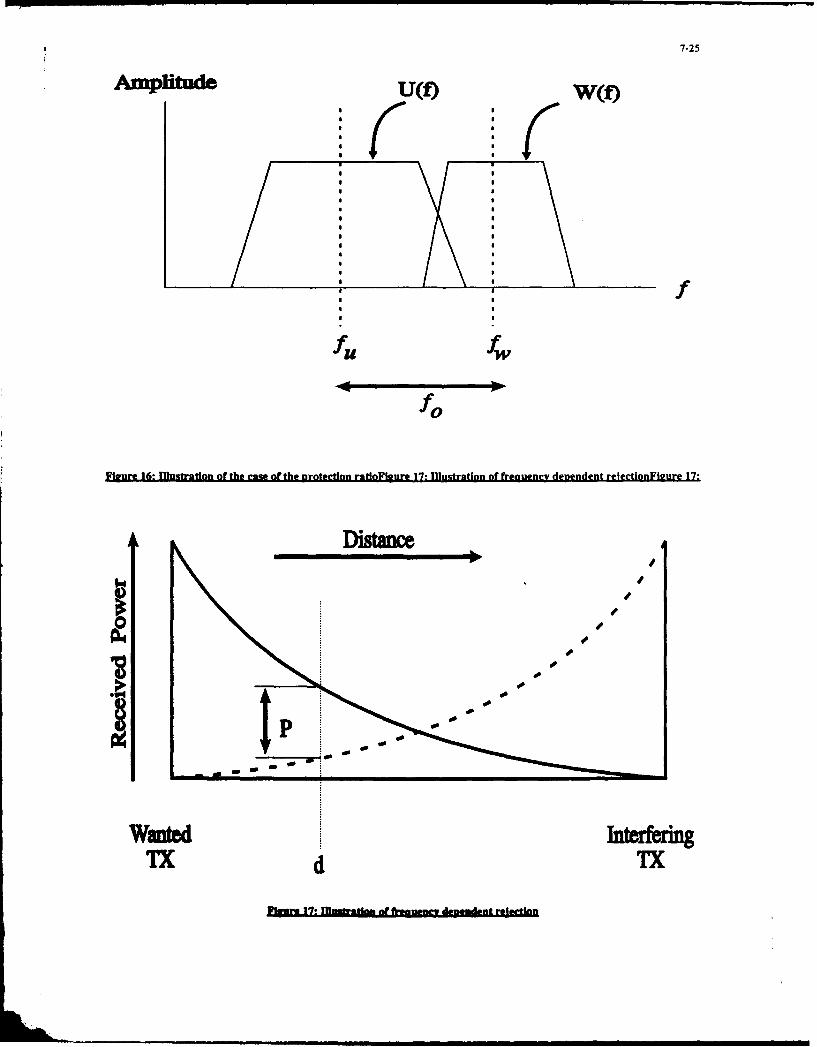
7-25
Amplde UM) W(f)
f
fU fw
fo
fPgeure 16: muhatratoa of the came of the Brotection ratoFigure 17o !Illutration of freguency dependent refection Figure 17:
Ditace
ot
Wanted ItrenTx d I
~~KK ~ ~ ftn d3 M f
8-1
MEASUREMENT ENVIRONMENTS AND TESTING.
Dr A.C. Marvin, Department of Electronics,University of York, York YOI 5DD,
United Kingdom.
Summary. performance standards and the test methods
required to ensure compliance with the
This lecture will describe the various standards.methods used to assess both the emission(interference generation) performance of The development of EMC standardselectronic equipment, and the immunity of began in earnest with the setting up of CISPR,electronic equipment to external the International Special Committee on Radioelectromagnetic interference. Interference in 1934. Various manifestations
of electromagnetic interference had beenThe measurement methods attempt to apparent before that date. Interference
simulate realistic operating conditions for the between early radio systems was one impetusequipment under test, yet at the same time towards the development of narrowthey must be repeatable, and practical to bandwidth tuned cw systems as opposed tooperate. This has led to a variety of test inherently broadband spark systems whichmethods being developed, each of which has took place during and immediately after theits limitations. The lecture will concentrate on First World War. The parallel large scalethe most common measurement methods such developments of broadcast radio and motoras open-field test sites, screened enclosures transport, which took place during theand TEM cells, and describe the physical nineteen twenties, resulted in the requirementjustification for the methods, their limitations for suppression of impulsive noise fromand measurement precision. electrical ignition systems on vehicles and, as
such, represents the first contact by the publicWays of relating similar measurements at large with an EMC problem. This is also an
made by different methods will be discussed, early example of an interference problemand some thoughts on future measurement between two engineering systems, one ofimprovements will be presented. which is neither an overtly electrical or tele-
communications system. The quasi-peakdetector, developed by CISPR to quantify the
1. Introduction. audio annoyance factor of this impulsiveinterference problem, and described below,
1.1 Historical Background. lingers on today in EMC measurementspecifications. The early EMC specifications did
The requirement for EMC testing arises not need to address disturbance to other thanfrom the need to control the electromagnetic radio and analogue equipment as theenvironment. The control is necessary in order thermionic valves and electro-mechanicalto ensure that systems operating in that switching used for the processing of signalsenvironment can do so without causing or required substantial energy inputs beforesuffering from electromagnetic interference, malfunction occurred.
The history of relatively large scale electricaland electronic technology, with the large scale The situation, as it exists today, has
use of electrical power and communications arisen from this historical background. Intechnology, is confined to the twentieth effect, two almost completely separate EMCcentury. The timescale has also coincided with communities exist. The commercial andother mass technological developments such as domestic electionics industry has slowly
land and air transport based on various forms evolved an EMC community as indicated,
of internal combustion engine. Whenever the primarily in the United States through the
use of technology expands in this way, the Federal Communications Commission (FCC),users of the technology become less concerned and Europe with (Western) Germany taking a
in the technology itself and more concerned leading European role through the VDE. Thiswith their own use of the technology as community has received a substantial boost
laymen. Regulation of the use and recently on both sides of the Atlantic with theperformance of the technology then becomes development of the European Communitynecessary in order to ensure a safe and Directive on EMC, now to be fully implementedequitable service. The regulation is in the in 1995.hands of national and international bodieswhich develop and promote the use of In contrast, the rapid developments ofstandards for equipment design and use. Part military electronics that occurred from 1934of the regulation process is the development of onwards with the parallel development of
8-2
radar in several countries led to substantial However, it would be unreasonable to expectmilitary EMC problems. As a result a military to operate a portable radio placed on top ofEMC community developed which achieved the computer VDU.maturity much earlier than the civilian sector.The US Military Standards for EMC are widely The complexity and uncertainty of theaccepted throughout NATO and form the basis environments in which electronic equipment isof other national standards, for example the operated necessitates some simplification andBritish Defence Standards on EMC. While partitioning for test purposes. The testing istrying to achieve the same aims, the test first split into interference emissionmethods and specified electromagnetic field assessment and assessment of immunity tolevels are very different for the two interference. (The term immunity is usedcommunities, the military standards in general interchangeably with the term susceptibility,being rather more stringent. with the military EMC community generally
using the latter term.) The next split considersthe energy propagation process, and this is
1.2. Considerations Leading to Test simplified into radiated and conductedMethods. interference assessments. The case of
capacitive/inductive coupling which forms anLet us now consider the overall overlapping area between radiated and
philosophy underlying EMC testing. The conducted interference is not consideredproblems arise because unwanted energy separately. Four types of test are thuscouples from one system to another causing identified as shown in Tablel.1 below.various levels of malfunction from slightperformance degradation through to Table 1.1. Types of EMC Test.catastrophic failure. Each problem has aninterference source and a victim. A simplistic Conducted Emission * Conducted Immunityapproach is to state that no interference *sources should exist, that is, systems should Radiated Emission * Radiated Immunitybe so designed that interference is notgenerated. Bearing in mind thatelectromagnetic waves, the medium by which The types of signals are also considered.interference is propagated, are generated by For measurements of emissions, the frequencyany time varying electrical signal, such a domain analysis is always undertaken usingrequirement would place impossible design special receivers, irrespective of the nature ofrequirements on the screening and filtering of the waveforms causing the emissions. Theseany system. Practical equipment will generate could be a set of cw oscillators in asome interference. Potential victim equipment communication system, or a set ofalso has to be capable of operation in the harmonically related signals from a digitalpresence of naturally occurring interference, clock as illustrated in Fig 1.1. Both of theseand so must be designed with some level of have line spectra. The emissions could alsoimmunity to interference. Thus, in order to have random or noise like properties asachieve electromagnetic compatibility, two generated by analogue or digital data signals.aspects can be identified, interference These have continuous spectra as illustrated inemission and immunity to interference. Each Fig 1.2. The problems associated with the wideequipment must be assessed for each aspect. range of signal types are addressed in the
section on receivers.The levels of interference generation
allowable and the and the immunity required For immunity measurements both timeof equipment are set by the regulating and frequency domain signal specifications areauthorities through specialist committees. used, the time domain specified signals beingThese consider the likely operation of the restricted to conducted immunity tests. Forequipment in terms of its surroundings, example, a specification may require anknown external threats and known potential equipment to be subjected to a modulated cwinterference victims. Such factors as the carrier swept or stepped across a givendistance to the nearest other equipment and frequency range, or the waveform andthe other types of energy propagation paths repetition rate of an impulsive signal may beavailable (power and signal distribution specified in the time domain. The twonetworks) are considered. The interference approaches are possible in the immunity caselevels are based on reasonable operation of as the signals are directly under the testersthe equipment. For example, it must be control.possible to operate a broadcast radio receiverin the same premises as a personal computer, 1.3. The Test Method Design Philosophy.and to the interference generated by thecompOter mast allow an adequate signal to The design philosophy of EMC test(noise + interference) ratio for the radio. methods merits some consideration before the

8-3
various test methods are described. Most tests These effects are discussed in more detail inare of the "go, no-go" type where an indication the sections describing the differentgreater than the specified level of interference measurement environments.is considered a failure and one below a pass,although in reality, some judgement may be For the measurement of emissions, theused for results close to the specification level, test environment need only accommodate theIn performing an EMC test we are assessing emissions from the EUT in as realistic a way asthe probability of an interference problem possible. The emissions are then detected byexisting. It is therefore more accurate to say an appropriate transducer and passed on to athat test procedures are performed rather receiver for subsequent analysis. The EUT isthan measurements, and that the outcome of exercised throughout its range of operation.the procedures indicates that either an EMC The frequency range of observation isproblem may occur, or that one is not likely to determined by the assessment of the threatoccur. The level of confidence in these that the EUT poses. For example, aassertions depends on the difference between commercial/domestic radiated emissionthe pass-fail level and the level of interference measurement is normally performed in theactually observed. This is not generally 30MHz to IGHz range. The upper limit is setquantified. by the use of the radio spectrum in the likely
environment of the EUT, as most terrestrialIn designing a test method we are radio services operated by unskilled users are
attempting to mimic a realistic operational in this range. A plot of the ambient spectrumenvironment for the Equipment-under-Test in a typical urban location at York, England is(EUT). In general, the working environment of shown in Fig 1.3. The spectral energy presentan EUT can only be defined in the broadest in most digital electronic equipment is alsosense and so the test environment is, at best, a becoming insignificant above this frequency,simplification of the real environment. It is although new systems with clock frequenciesonly necessary to mimic the electromagnetic in excess of 100MHz are required to be testedenvironment of the EUT so other factors such to higher frequencies in the USA. Belowas temperature or humidity need not be 30MHz it is observed that most interferenceincluded. If the ambient electromagnetic energy propagates in the form of conductedenvironment is present in the test, the interference as the efficiency of the radiationassessment of interference may be subject to process is reduced as the frequency reduces.interference. In conducted interference In this frequency range conductedmeasurements this is relatively straight interference assessments are made. Theforward, as both power and signal cables can military EMC community has more stringentbe filtered. In radiated interference requirements, and requires both radiated andmeasurements exclusion of the ambient conducted emission measurements to be maderequires screened enclosures. If these are over a wider frequency range, although theanechoic then they present no problems. At conducted tests still occupy a lower frequencylow frequencies however, anechoic range than the radiated ones.performance cannot be obtained, and the testenvironment is degraded. Screened and In the case of immunity assessments, thefiltered measurements are also required if requirement to mimic the operationalsignal security is an issue. environment poses a further problem. The
immediate electromagnetic environment of theA further issue is that of measurement EUT can be constructed in the same way as
repeatability and precision. No two test that for emissions assessment. For immunityenvironments are identical. There is, for assessments, the threat fields must also beinstance, a multiplicity of screened enclosure present. In operation, the EUT will besizes on the market, and test houses tend to illuminated by a variety of threat fieldsbuy the enclosure that fits their premises and simultaneously. Each will have its ownbudget. While the specifications may be quite direction of arrival, polarisation, modulationdetailed in its description of the layout and and intensity. Except for specialist militarydimensions of the antennas etc used inside the threat simulators, the multiplicity of threatenclosure, they reflect the multiplicity of sizes fields is simplified to either a single pulseusually by only inferring a minimum size train or modulated carrier swept over thethrough minimum antenna to wall spacings. predetermined frequency range. Clearly, thisOpen-field test sites used for radiated is a considerable simplification of the actualemission measurements are also of variable threat, but the economics of the test processconstruction because of minimum rather than generally precludes any more complex effort.actual conducting groundplane sizespecifications. These constructional As with the emission assessment, thevariabilities lead to poor repeatability of EUT must be exercised over all its functions.measurements between facilities, particularly This is much more time consuming forin screened enclosures where enclosure immunity. For emission assessment, aresonances cause considerable variability, frequency scan can be taken relatively quickly

8-4
for each EUT state, as for each state, the the wavelength. The 3m site, in particular, isemission spectrum is usually stable, and the marginal for a 3770 wave impedancescan rate is limited by receiver considerations. assumption. The maximum EUT size is limitedThe receiver output data is presented in graph by the Rayleigh Range criterion of a minimumform, and a pass-fail judgement can be made EUT to antenna spacing of 2D2/) where D is thequickly by comparison with the specification. maximum dimension of the EUT. This criterionFor immunity assessment, the EUT must be is determined by the need to makeassessed at all frequencies for each EUT state measurements in the Fraunhoffer diffractionwith sufficient dwell time for the tester or a defined far-field of a radiating system. Fordata logger to observe any effect. Often the measurements at I GHz (X = 0.3m) on a 3m site,observation may be subjective. For example, the maximum EUT dimension set by thethe interference effect may be a degradation Rayleigh Range criterion is 0.7m.of a video display or audio signal, or it may bean instrumeat reading error comparable with The minimum clear area is defined bythe inherent accuracy of the instrument. Such the EUT to antenna spacing by an ellipse withassessments take time and are operator the antenna and the EUT at the foci, and thedependent. major and minor axes being 2.0 and /3 times2.0 Survey of Test Methods. the focal distance of the ellipse. This geometry
gives an EUT to ellipse perimeter to antenna
In this section the various types of test distance of twice the focal distance and thusmethods are reviewed. The section is divided defines the maximum spurious reflection fromaccording to the test types identified in section objects outside the ellipse. lIn the worst case of
1.2 with the addition of a section on receivers, a large specular reflector on the perimeter,tangential to the ellipse, the spurious reflectedsignal would be no more than half the direct
2.1. Radiated Emission Measurements. signal. Within the ellipse the ground isrequired to provide a specular reflection and
Two techniques will be described for thus must be flat to within X/16 at theperforming radiated emission measurements, shortest wavelength as a rule of thumb. As thethe Open-Field Test Site (OFTS) and Screened highest frequency of operation is IGHz, thisEnclosures. The former is used primarily by requires a surface level to within about 20mm.the commercial/domestic EMC community, The conducting groundplane is present to givewhile the latter is used mainly by the military a repeatable ground reflection, independent ofEMC community. the ground moisture content, over as much of
the site as possible. Its minimum size, asSpecifications for radiated emissions are specified in BS6527 [2], is shown in Fig 2.2. If
defined in terms of the radiated electric field possible the conducting groundplane shouldincident upon a receiving antenna. The signal cover the whole site. It must be present overreceived by the antenna is measured as a the area shown in order to provide;voltage in a receiver operated with a specifiedbandwidth and detector type, and is related to i) a defined specular reflection at thethe incident field by the antenna factor (A.F.) mid- point between the EUT and the anrenni.of the antenna defined as;
ii) a defined reflection coefficientA.F. = EV in-i beneath the antenna to stabilise the
antenna- ground interaction.where E is the magnitude of the incident field
and V is the receiver input voltage. The iii) a defined reflection coefficientantennas are calibrated along with their beneath the EUT to stabilise the EUT-interconnecting cable, and many receivers give ground interaction.their output as incident electric field ratherthan input voltage, the antenna factor being On outdoor sites the conducting groundplane isstored in a look-up table in the receiver, made from a mesh material in order to aid
drainage. A mesh size also less than X/16 atA plan view of an OFT'S as defined in the shortest wavelength (20mm) is required
CISPR Publication 22 [11 is shown in Fig 2.1. so that the mesh behaves as a continuousThe site should be on level ground as far away reflector.from buildings and other potential reflectingobjects as possible. The EUT to antenna spacing A side view of the site is shown in Figis fixed at 3m, 10m, 30m, 100m, with the first 2.3 which illustrates the various interactionstwo being the most common. These distances between the antenna, the EUT and theirare chosen to be representative of typical images. From this it can be seen that the totaldistances over which interference may occur. field present at the antenna is the phasor sumAt 30MHz, the antenna to EUT spacing is X/3 of the direct wave and the ground reflectedfor a 3m site and X, for a 10m site where X is wave. The value of this sum depends on the

8-5
path length difference between the direct and performance. The ±3dB figure is a recognitionreflected paths in wavelengths. For a given that most sites are constructed inantenna height this is dependent on unfavourable locations with nearby buildingsfrequency. If the value of the sum is plotted and other reflecting objects. It defines thefor a set of frequencies against antenna height, precision of the measurements made on thea result similar to that of Fig 2.4, recorded by site and the repeatability of measurementsFitzGerrell [31 at NIST Boulder, is obtained. The made on different sites. Because of this factormeasurement specification calls for the many test houses only issue unrestrictedmaximum value of the resultant interference clearance to EUTs with emissions more thanpattern to be recorded for each frequency. In 6dB below the specification limit.the frequency range from 30MHz to 300MHz abroadband Biconical Dipole is often used as the Screened enclosures are used forantenna. From 300MHZ to IGHz a log-periodic radiated emission measurements inarray is used. In some cases more precise circumstances when the presence of themeasurements of the most significant emission ambient radiation is undesirable. Screenedfrequencies are made with resonant X/2 rooms are used by the military EMCdipoles. community over a frequency range from
below 10kHz to above 18GHz [4,5] for allThe measurements are repeated for both radiated emission measurements. The
horizontal and vertical polarisation of the commercial EMC community uses them forantenna, and the EUT is rotated in the diagnostic measurements and in me caseshorizontal plane to ensure that the worst case screened enclosures can be made to simulateradiation is received. In many cases, the major an OFTS.repeatability problem is caused by the layoutof power or signal cables effecting the radiated Enclosure sizes vary in the mainfields. For a typical 19" (0.5m) dimension between 3m x 3m x 2m and 20m x 20m x 20mequipment with a 2m long mains cable, the with some exceptions on either side of theseEUT is between X/4 and 8X in length. limits. The larger enclosures, capable ofIndividual circuit cards and sub-assemblies do housing full size vehicles or aircraft, are foundnot radiate in their own right to any great in relatively few locations usually associatedextent, however they do excite the whole with national facilities or large manufacturers.structure including the cables which then The majority of enclosures have floor areasradiates. The radiated fields are then highly less than 10m x l0m.
dependent on the cable layout. Somespecifications call for the cable to be placed to The operation of the enclosure as aensure maximum radiation. As the radiation measurement environment is determined byefficiency of any particular layout is highly the size of the enclosure relative to thefrequency dependent, this procedure needs to wavelength of the radiated emission to bebe repeated for each frequency examined, measured. At microwave and UHF frequencies,
the enclosures can be made anechoic byThe quality of an OFTS is assessed by covering the walls, ceiling and possibly the
measuring its site attenuation. This is a floor with radio absorbent material (RAM).measure of the signal transmission between The use of RAM in anechcic chambers used fortwo resonant X/2 antennas placed on the site antenna measurements is well known. Theat the antenna and EUT positions as shown in typical reflectivity level of -40dB associatedFig2.5. The maximum value of the measured with RAM in this application is not requiredsignal as one of the antennas is scanned for EMC measurements where the acceptablevertically from Im to 4m is compared with precision is lower. Good performance can bethat received when the two connecting cables obtained with a RAM reflectivity level noare joined together. This is the attenuation better than -20dB. As a result the depth ofintroduced by transmission over the site. The RAM required is about X/4 and this sets thesite attenuation can be computed for balanced lowest attainable frequency of anechoicdipole antennas over an infinite perfectly operation for a given enclosure size. For mostconducting groundplane by defining the self small chambers the RAM depth is limited toand mutual impedances of the two antennas about 0.5m giving a lowest anechoic frequencyand their images. The resultant 4x4 impedance of around 150MHz. The larger chambers havematrix is inverted to compute the response. RAM depths up to 2m giving claimed anechoicFor a ;ie to be acceptable, the measured site performance down to 30MHz. The eventualattenuation must lie within a ±+3dB envelope of limitation on RAM depth is mecl anical supportthe computed figure. The theoretical site and the economics of enclosure design. Inattenuation is shown in Fig 2.6. The points order to use the low frequency RAM a largenear the curves are measured values of the enclosure is required with consequentNIST site at Boulder, Colarado [3]. This site has increased wall area. Medium size chambersa 60m square groundplane, aid thus have been built with RAM on the walls andrepresents the best likely attainable ceiling leaving a conducting floor, and these

8-6
are able to be used as OFTSs above about frequencies of these resonances for an empty100MHz [6]. rectangular enclosure of dimensions a , b x c
is given by;The frequency range below that at which
an enclosure can be made anechoic can be fpqr = 150((p/a) 2 + (q/b) 2 + (r/c) 2 )1/ 2 MHzdivided into three regions dependent on theprincipal means of energy propagation within where p,q,r are integers, one of which may bethe room [7]. The lowest frequency range, up zero. In addition, TEM resonances of theto a frequency at which the maximum linear conducting bench are present. The benchdimension of the enclosure is approximately perturbs some of the cavity resonantX/10, can be treated as a quasi-static problem. frequencies, and the EUT and antenna alsoNo appreciable phase shift occurs in wave modify the resonant frequencies. Thepropagation across the enclosure, and the frequency response of a small enclosure ofcoupling of equipment to an antenna can be dimensions 2.25m x 2.25m x 4.5m with aanalysed in terms of mutual capacitive and conducting bench and biconical antenna isinductive elements in an equivalent circuit, shown in Fig 2.12. The excitation source is aSuch a circuit is shown in Fig 2.8 and is short dipole placed at the EUT position on theequivalent to the EUT and antenna layout bench.inside a screened enclosure shown in Fig 2.7.In the capacitive coupling case the antenna is Consideration of the low frequencya 41" active rod antenna as specified in Def operation of screened enclosures for radiatedStan 59-41 and Mil Std 462 for the emission measurements shows that themeasurement of radiated electric fields. The measurements are not directly equivalent tosurface of the enclosure and the conducting measurements performed on an OFTS. Thebench that the EUT is placed on is an equi- energy propagation mechanisms present in thepotential surface. enclosure are different to electromagnetic
radiation. The various resonance phenomenaThe next frequency range is that up to can impose measurement uncertainties of up
30MHz, the upper frequency of use of the 41" to +40dB unless steps are taken to remedyrod antenna. The conducting groundplane and their effects. A number of studies areits extension can be regarded as the inner underway in the UK and elsewhere aimed atconductor of a coaxial transmission line that evaluating ways of reducing the resonancesupports a Transverse Electro-Magnetic (TEM) effects using various forms of dissipativewave propagating from the EUT to the dielectric and magnetic materials positioned atantenna. If the EUT is regarded as a set of field maxima inside the enclosures [81. Theelectric and magnetic dipoles, then these eventual aim is to reduce the resonancecouple into the TEM mode through their induced coupling variations to +5dB. While itmutual capacitance and inductance with the may seem that the use of an enclosure fortransmission line. The bench bonded to the radiated emission measurements is prone toscreened room wall is a short circuit, and the considerable error, it should be rememberedactive rod antenna is a capacitive load at the that the oscillating charges and currents thatend of the line. The change in width between cause radiation in free space are those thatthe bench and the groundplane extension is a excite the various coupling mechanisms in achange in line impedance with its associated screened enclosure. The enclosurediscontinuity capacitance representing the measurement, in principle could be used tostored energy associated with the field evaluate free space radiation. The assumptionperturbation at the discontinuity. Equivalent here is that the presence of the enclosure doescircuits for the two coupling modes are shown not interfere with the oscillating sources.in Fig 2.9 and the associated frequency Recent experimental work has shown this toresponses for a typical screened enclosure are be the case for magnetic dipole sources but notshown in Fig 2.10. The resonance at 35MHz is for electric Jipole sources [91associated with X/4 resonance of thetransmission line system, and the coupling nullat 17MHz is due to mode competition betweenthe direct capacitive coupling from the EUT to 2.2 Conducted Emission Measurements.the antenna dominant at low frequencies andthe TEM coupling dominant at higher The measurement technique used forfrequencies. making conducted emission measurements is
determined by the type of current flow on theIn the frequency range from 30MHz to conductors. Both common mode and
200MH'Iz a different enclosure set-up is differential mode emissions requirerequired as shown in Fig 2.11. A biconical assessment. Common mode currents flowingdipole antenna is used to measure the fields. If on a conductor set such as a power cable arethe enclosure is not snechoic in this frequency an important source of radiated emissions, andrange, cavity resonances will be present. The in some circumstances, measurements of

8-7
common mode currents can replace radiated accomplished using an absorbing clamp as
emission measurements. shown in Fig 2.15. This comprises aconventional current probe immediately
Common mode currents are measured followed by a series of ferrite rings made fromusing some form of current transformer. In its a ferrite material which exhibits loss at radiosimplest form it comprises a toroidal core of frequencies. The cable to be assessed is placedhigh permeability material, through which the on a bench and the clamp is moved along thecable carrying the common mode current is cable. The maximum value of the residualpassed. The time varying common mode current standing wave is measured.current induces a time varying magnetic fluxin the toroid. A sense coil is wound around the Differential mode currents are measuredtoroid, and the induced voltage, a measure of using a network inserted into the cable knownthe changing flux, is measured by the receiver, as a Line Impedance Stabilisation NetworkThe system is shown in Fig 2.13. The (LISN). This is a simple circuit which managesfrequency response of the system is shown in to fulfil three requirements.Fig 2.14. Above the frequency where thereactance of the sense coil is greater than the i) It defines the impedance seen by theinput resistance of the receiver, the system is differential mode currents on the cable.frequency independent. It is characterised by This is necessary in order to perform aa transfer impedance, measured in dBL2, which repeatable measurement. The r.f.is the relationship between the received impedance of a domestic 240V supplyvoltage and the source common mode current. varies between Oi and 200fl resistive
and ±2000l reactive. A suitableCurrent probes measure the total standard impedance in this range is 50fi,
common mode current on a cable. They cannot the input impedance of most
distinguish between currents on an individual
conductor within a cable, unless that conductor measurement receivers.
is passed through the probe in isolation. Care ii) It reduces differential modemust be taken to ensure that the current interference propagating away from theprobe toroid is not saturated by large direct or EUT thus isolating the EUT.power frequency currents as the change indifferential relative permeability reduces the iii) It reduces other r.f. currents on thetransfer impedance. Current probes can be cable reaching the EUT thus reducingobtained for frequency ranges up to 1GHz. The interference with the measurement.normal design value of transfer impedance isIl (OdBfl) thus eliminating the need for A circuit diagram of a LISN is shown in Fignumerical conversion between measured 2.16.voltage and common mode current. As a Its performance in terms of the impedancecurrent probe is essentially a transformer in seen by the EUT is shown in Fig 2.17. As thewhich the cable to be sensed forms a single differential mode currents are terminated by aturn primary winding, the effect of the current standard impedance they are assessed inprobe is to insert a small series impedance terms of r.f. voltage at the output of the LISN.into the cable. The value of this impedance The switched resistors ensure that each line isdepends on the receiver input impedance, the terminated in the same impedanceturns ratio and the other parasitic effects irrespective of which line the receiver isassociated with a transformer. In general the switched to. The layout of a conductedinserted impedance is less than lQ. In a multi- interference measurement according to Def
conductor cable, the distribution of the series Stan 59-41 is shown in Fig 2.18.impedance is not easy to determine as itdepends on the termination impedances ofeach conductor and the cross-talk between 2.3. Measurement Receivers.them.
In this section the instrumentation used
As, at higher frequencies, the common for emission measurement is considered. As
mode current on cables is a primary source of the interference waveforms are indeterminate
radiated emissions, a common mode current and, for the most part, we are seeking to
measurement can replace a radiated emission protect radio services, emission levels are
measurement. This is an attractive option in defined in the frequency domain. The
view of the problems associated with making interference is then measured on a receiver of
reliable and repeatable radiated emission defined bandwidth and detector function. The
measurements. The main problem with a receivers used all use the superheterodyne
current probe measurement at higher architecture. They are classified into two
frequencies arises from standing waves set up types;on the cable. These can be largely eliminated ifthe common mode current on the cable is i) Spectrum analysers. These are relatively
terminated in an absorbtive load. This can be cheap and provide a quick visual display of

8-8
their input spectrum. Most spectrum analysers Clearly the definitions lead tooperating in the frequency range below their classification difficulties. Strictly speaking, thefirst IF frequency (about 2GHz) have only an broadband definition should be sub-dividedinput low-pass filter, with no tuned pre- into continuous spectrum noise like signalsselection before the first mixer. This means and line spectrum repetitive or impulsivethat all the incoming energy is presented to signals. This is important when considering thethe mixer. If the interference is impulsive, detector input energy to bandwidththen, while the mean energy may be low, the relationship. For a continuous spectrum noiseinstantaneous peak energy can be sufficient to like signal, the detector input energy isoverload and possibly damage the mixer proportional to the bandwidth and hence adevice. Spurious signals can thus be generated bandwidth increase of a factor of ten results inwithin the analyser, and unless steps are a detector input power increase of 10dB. Intaken to identify them the results of emission the case of an impulsive signal with a series ofmeasurements from spectrum analysers are phase related spectral lines, the bandwidthsuspect, increase of ten results in an increase of ten in
the number of spectral lines incident on theii) Measurement Receivers. Measurement detector. As the spectral lines are phasereceivers have tuned pre-selector filters related, the detector input voltage is increasedbefore the first active stage and thus limit the by a factor of ten (20dB) and hence theinput energy to that stage. This may take the detector input energy increases by 20dB.form of a tuned filter, a switched filter bank ora combination of both. They do not suffer to Two detector types are in common usethe same extent as spectrum analysers from for EMC measurements, the peak detector andspurious responses and they have a wider the quasi-peak detector. The peak detector isdynamic range. The requirement to tune or more common in military usage whereas theswitch the pre-selector filter means that the quasi-peak detector is used by the commercialtuning rate of a receiver is less than that of a EMC community. Both detector types comprisespectrum analyser, and traditionally receivers a conventional diode detector followed by ahave been manually tuned with a meter charge -discharge circuit with defined chargeindication of the received signal strength. Most and discharge times. The peak detector has areceivers also have audio de-modulation very short charge time and a relatively longfacilities and a speaker which are not discharge time. It thus measures the peakgenerally found on a spectrum analyser. voltage of any input signal. For sinusoidal and
other similar narrow band signals it can beModem design has resulted in a scaled to read the r.m.s signal level.
synthesis of the best of both receiver types byuse of computer control, data storage and The quasi-peak detector is designed todisplay. Receivers now have VDU display of have an output which responds both to thethe spectrum and spectrum analysers have amplitude of the input signal and to thepre-selector options giving them receiver-like repetition rate of impulsive signals. Thus anperformance. The add-on pre-selectors cost impulsive signal with a higher repetition ratemore than the basic spectrum analyser! but the same amplitude than another signal
will give a greater output. The design of theThe main conceptual difficulties with quasi-peak detector is configured in this way
receivers lie in the selection of measurement to indicate the subjective annoyance value ofbandwidth and detector type. Receiver repetitive signals on audio and video signals.bandwidths are selectable with values in the It is not adequate however to indicate bitrange 100Hz to IMHz. The signals to be error rates in digital systems. As the output ofmeasured can be classified into two types, the quasi-peak detector is much less than thebroadband and narrow band. A broadband peak input signal, the associated r.f. mixer andsignal is one with a spectrum extending IF stages must be capable of reproducing thebeyond any filter bandwidth available on the full amplitude of the impulsive signal. Thus areceiver. The amount of energy incident on the considerable signal overload factor relative toreceiver detector varies with the the indicated output level must be built intomeasurement bandwidth and thus any these stages. The quasi-peak detectormeasurement must have a defined bandwidth. functions by having detector charge andRandom noise and impulsive signals are discharge times related to the IF bandwidth.generally broadband. The IF bandwidth is related to the receiver
input frequency as shown in the table below.A narrowband signal is one with a
spectrum narrower than the receiverbandwidth. Thus most analogue radio signalsand individual clock harmonics arenarrowband signals. The energy incident on 4
the detector is independent of the receiverbandwidth.

8-9
Table 2.1. Quasi-Peak Detector gain G available from the transmittingCharacteristics. antenna. If the intrinsic impedance of free
space is Z, and the EUT to antenna distance is RInput Frequency Range then,
1-l$OkHz 0.15.30MHz E2JZ = Pt. G / 4x.R2
peak bandwidth 100-500Hz 7-10kHz Examination of this equation indicates apossible advantage in using high gain
quasi-peak 200Hz 9kHz antennas. This is not the case as two furtherbandwidth factors need consideration. The first is that the
antenna only exhibits its full gain at distancescharge time 45ms Ims beyond the Rayleigh range, a diffraction
limited effect. If the antenna maximumdischarge time 500ms 160ms dimension is D and the wavelength is X then
IF overloadfactor 24dB 3dBR > 2D2
Input Frequency Range. is required to realise G. As the gain of anantenna of radiating aperture say D2 is
30-300MHz 0.3-1GHz G = 4x.D 2l ,2
peak bandwidth 100-300kHz 100-500kHzit can be seen that the greater the gain G the
quasi-peak 120kHz 120kHz greater the distance R needs to be. The secondbandwidth effect is the relationship between the 3dB
beamwidth of the antenna 0 and hence thecharge time Ims Ims area of the EUT illuminated by the antenna
and the antenna gain. The approximatedischarge time 550ms 550ms relationship is,
IF overload G = 4X/92
factor 43.5dB 43.5dBThe higher the gain of the antenna, the
The relative responses of peak and narrower the beamwidth, and hence for aquasi-peak detectors are shown as a function given size of EUT, the further away theof pulse repetition rate in Fig 2.19. Calibration antenna needs to be to ensure that the wholeof a quasi-peak detector is made using a EUT is illuminated. It is left as an exercise forstandard r.f signal generator generating a the reader to show that the transmitter powersinusoidal signal. Under these circumstances required to illuminate a given size of EUT isthe two detector types give the same independent of the antenna gain if the aboveindication, illumination criterion is followed.
2.4 Radiated Immunity Measurements. There is considerable advantagetherefore in minimising the antenna to EUT
In this section the basic techniques of distance, and hence screened enclosure size,performing radiated immunity measurements by using a low gain antenna, provided that theare discuted. Rayliegh range criterion and the minimum
distance requirement for a 3770 waveRadiated immunity assessments require impedance ( R > /2x) are satisfied.
that the EUT be illuminated by a propagatingelectromagnetic wave of the required At lower frequencies, where thefrequency and field strength. As the frequency enclosures cannot be made anechoic, cavityis stepped or swept over a substantial resonances can cause considerablefrequency range and field strengths of up to measurement uncertainty. Problems also arise200V/m are required it is normal to perform at even lower frequencies because the 3770these assessments in shielded enclosures. Onceagain, the mode of operation of the enclosure wave impedance criterion results in an
is determined by the frequency range of the unacceptable EUT to antenna distance. Various
assessment. At frequencies where the techniques are used to overcome the problems
nclosure can be made anechoic, the EUT can including at the lower frequencies the use of
be illuminated by a wave generated by a capacitor and inductor like field generators
conventional antenna as in free space. The r.f. that produce localised high impedance(electric field) or low impedance (magnetic
power required Pt can e evaluated b d field) waves.considering the required threat field B and the[
8-10
A better technique for producing plane mode. In the case of immunity measurementselectromagnetic waves at low frequencies is to we are not restricted only to the frequencyuse a Transverse ElectroMagnetic (TEM) wave domain, and threat currents or voltages in thegenerator such as the Crawford Cell. Such a form of impulses can be used.device is shown in cross-section in Fig 2.20.The cell comprises a tapered transmission line One aspect of conducted immunityof square cross-section with the inner assessment is now starting to replace radiatedconductor in the form of a flat septum. The immunity assessment on large systems such astapered cross-section maintains a constant aircraft. The power and space requirements ofcharacteristic impedance on the transmission radiated immunity assessment of a largeline from the coaxial input to the working system can be prohibitive. As a rule it isvolume and on to the matched load. The cell recognised that the energy propagation pathgeometry is chosen to give a 5001 characteristic into susceptible systems is via currentsimpedance for the transmission line (voltage induced onto cable bundles by the incidentto current ratio for a wave propagating on the wave. The first part of this energy transferline) while the air dielectric ensures an electric process can be avoided if interfering currentsto magnetic field ratio of 377Q. Within the are directly injected onto the appropriateworking volume, the fields mimic those of a bundles. This bulk current injection techniqueplane wave. The Crawford cell operates from is useful if the relationship between thed.c. to an upper frequency set by the onset of incident threat field and the induced current ishigher order modes than the wanted TEM known. The relationship can sometimes bemode. These occur at a frequency when the deduced by numerical modelling or bycross-section of the cell becomes X/2, but their illuminating the large system with a lowonset can be delayed by careful use of incident field and measuring the inducedabsorbing material in the cell. The maximum currents. An assumption of linearity can thensize of EUT is limited to one occupying one be made to deduce the induced currents fromthird of the septum to wall dimension if a full threat field. Neither of these techniquesacceptable field perturbation is to be is completely satisfactory, as incorporation ofmaintained. Thus the maximum frequency of the non-linear behaviour of the susceptibleoperation of a Crawford cell is set by the size systems is difficult in both cases. Fig 2.21of the EUT, the larger the EUT the lower the shows a test system for bulk current injection.maximum frequency.
3.0 Conclusions and Future Directions.The electric field E inside the cell can be
calculated from the voltage V applied to the In this paper I have attempted to givecell and the septum to side spacing d. an overview of some of the current
measurement and test techniques used forE = V/d Volts/in EMC assessment. The treatment is necessarily
incomplete, and no mention has been made ofand the magnetic field H is ElectroStatic Discharge measurements. New
measurement techniques are underH = E/377 = V/377.d A/m development in several areas. Much work is
underway on screened enclosure techniques atFor a 50(1 characteristic impedance cell, the low frequencies below the anechoic limitpower Pc required for an electric field E is frequency. The large uncertainties caused toPc = (E.d)2/50 Watts both immunity and emission measurementsOther types of TEM cell are used including are not acceptable and resonance dampingparallel plate transmission lines. The techniques and enclosure/antenna systemprinciples of operation are identical. In the calibration techniques are under development.case of the parallel plate lines, the fields are These are at relatively early stages but maynot confined as in a Crawford cell and the be incorporated into revised standard in thesurroundings can cause considerable field future.perturbation.
The problems of EMC assessment of largesystems are also attracting attention,
2.5 Conducted Immunity Measurements. particularly in the commercial EMCcommunity where large distributed computer
The techniques used for conducted systems within buildings and electronicimmunity assessments ae based on the same telephone exchanges represent currentcurrent and voltage transducers used in problems. The move to low energy low voltageconducted emission assessments. Detail logic families and poorly screened plasticchanges in design to accommodate the greater equipment enclosures enhances problems, andpower requirements of immunity assessment the screening performance of whole buildingsmay be made. Again, two operation modes can is an important consideration whenbe identified, common mode and differential considering these distributed systems. The

8-11
advent of optical data transmission has notproven to be the solution of EMC problems assome originally thought. While considerableamounts of data can be transmitted this way,power still goes along copper, as doesinterference. The systems at the end of thefibres are still electronic.
References.
[1] C.I.S.P.R. Pulication 22 "Limits andmethods of measurement of radio interferencecharacteristics of information technologyequipment." CEI 1985 Geneva.
[2] B.S. 6527 "Limits and methods ofmeasurement of radio interferencecharacteristics of information technologyequipment." British Standards Institution1988.
[31 R.G. FitzGerrell "Standard LinearAntennas" IERE Conference On EMC,Conference Publication No 71 pp1 4 7 - 15 3 . York1986.
14] MIL-STD-462. "Test Methods forElectromagnetic Emission and Susceptibility."U.S. Department of Defence.
[5] Defence Standard 59-41 Part 3 "EMCTechnical Requirements Test Methods andLimits." U.K. Ministry of Defence.
[6] S.A. Stone & S. Kashyap "CorrectionFactor for Relating Measurements Made in anAbsorber Lined Chamber to MeasurementsMade on an Open Fiels Site." IEEE Symposiumon EMC. pp362 - 365. San Diego 1986.
[7] A.C. Marvin. "The Operation of Antennasinside Non-anechoic Screened Enclosures." lEEConference on Antennas & Propagation. York1987.
[8) L. Dawson & A.C. Marvin. "New ScreenedRoom Techniques for the Measurement of RFI."J.I.E.R.E. Vol 58, No 1. pp28-32, Jan/Feb 1988.
19] A.C. Marvin & G. Simpson. "A controlledElectrically Small Antenna for the Evaluationof Radiated Emission Testing." IEE Colloquiumon Electrically Small Antennas. London 1990.lEE Coil Dipest No 1990/136.
w III

8-12
g7dBi 2. 50MHz 5MHz
I- -
L . ..... ... a. .... L _ --.. ..
ST lATT 10dBFig 1.1. Spectrum of Harmonics from a Digital Circuit.
97dB 2._50MHz 5MHz
-I-A
- I -i
ST is!_ ATT 10dB[ Fit 1.2. Continuous Spectrumn of Digital Data.

8-13
97dBu 500MHz 1GHz~T 10/
--------------------------------------- i---
Maw dimtr 1
DmMajor diameterined Fy
Mino dioef -r~~ xJY
_i 2..Pa iwifa rS

8-14
...... .....
L
D = d + 2 a. wbere d is the maximum test unit dimesi on;V z a * I a. where a is the maximum aerial diSesiOm;L a 3, 10, or 30 a.
Fig 2.2. OFTS Groundplane Minimum Area.
TestAntenna
DOW I<;tt
EUTO
CbeRefteled Path Rok
-odck G~mW _
Fig 2.3. Side View of an OFFS.

8-15
DIPOLE HEIGHT VS INSERTION LOSS ... HPs.e
FREQLENCIES, L TO R:
G.e. 30, 97, 311, 100 110HZ
4.0 -. .. ..
2.8.
10. 1.0 20.0 25.0 30.0 3S. 0 4. 45.0 50.0
RELATlRE INSERTION LOSS, DBSelected relative insertion loss data calculated forhorizontally polarized, dipoles over perfect ground. Siteattenuation is the single minimum insertion loss value ofeach curve. Separation distance is 3 a; transmitting dipoleheight is 2 a.
Fig 2.4. Vertical Interference Patterns on an OFTS.
/, taedI ,,~.. °°'''"" "
3a
30esi gnalGoeratO?
Icoadecling gromad plae
F.
Fig 2.5. Antenna Positions for OFTS Site Attenuation. i
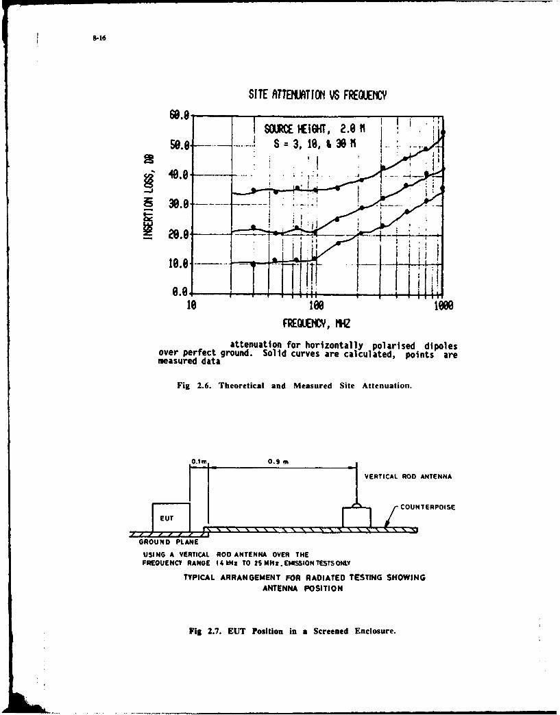
SITE RTTEUt*TIO1 VS FREOLMIC
20.-
0.01
FREMM4O, MW
attenuation for horizontally polarised dipolesover perfect ground. Solid curves are calculated, points aremeasured data
Fig 2.6. Theoretical and Measured Site Attenuation.
0.1 M 0.9 M
VEITIA ROD ANTENNA
COUNTERPOISE
GROUND PLANE
USING A VERTICAL ROD ANTENNA OVER THEFREQUENCY RANGE 14kHz TO 2S MHz. EMISSION TSTS OII
TYPICAL ARRANGEMENT FOR RADIATED TESTING SHOWINGANTENNA POSITION
Fig 2.7. EUT Position in a Screened Enclosure.

8-17
amplifier input capacitance
electric VreceLi{ Vi
creene dipole to anennarolls ante!nna capacitance
wallscapacitance
Fig 2.8. Equivalent Circuit for EUT to Antenna CapacitiveCoupling.
/ CCM
CA2
- o-
&)electric dipole source
89ck wonCA
VAAM
w LO
b)mgnetic dipole source
Fig 2.9. Equivalent Circuits for TEM Mode EUT to AntennaCoupling.

8-18
A/R log MAC 10 dB/ REF -10 d9
eleciric dipole source
START 1.000 000 MHz STOP 51.000 000 MHz
A/R log AG 10 d8/ REF 0 dB
IND1
magne ic di le so rce
START 1.000 000 MHz STOP 51.000 000 MHz
Fig 2.10. Frequency Responses for Circuits of Fig 2.9.

48 1CIA 0.3m
'5.GROUND PLANE 7
BICONgCAL AS VIEWED FROM EUT
Fig 2.11. EUT and Antenna for 30 200.v1Hz.
A/R log MAO 10 d8/ REF -aO 41
START 50. 000 000 M#~z STOP 200.000 000 M9Hz
Fig 2.12. Frequency Response of Screened Enclosure 30200MHz.
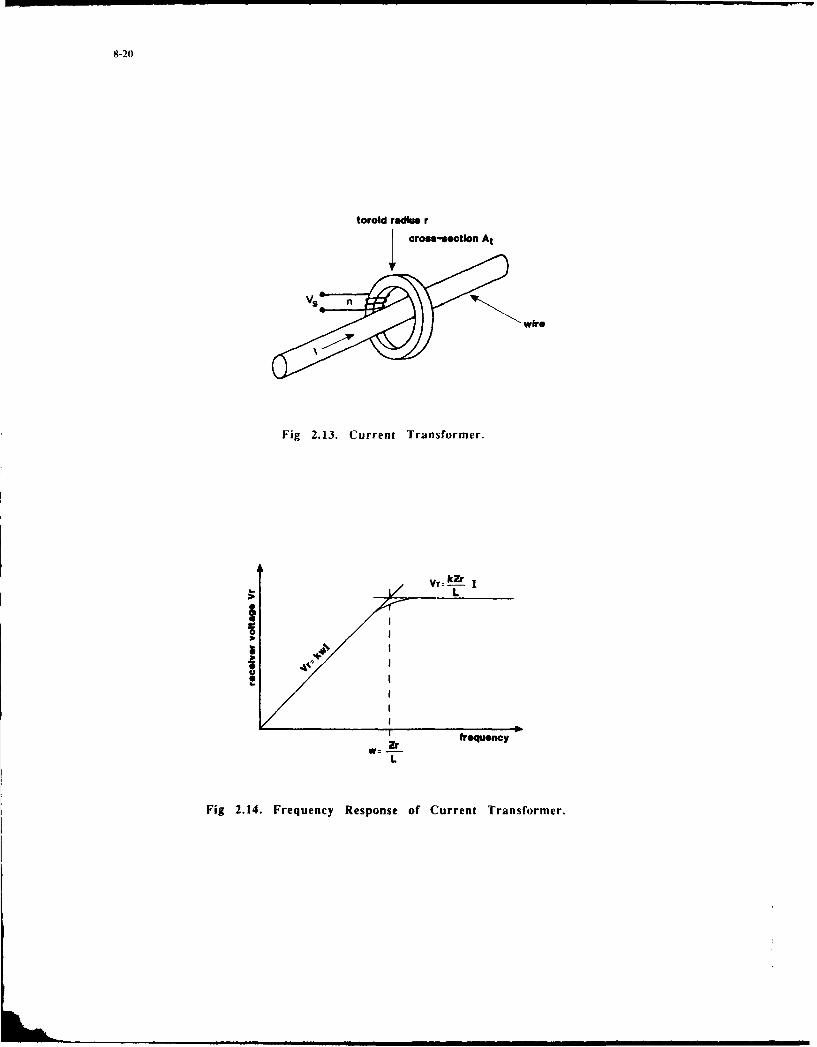
8-20
torold radius r
I crosa-ction At
wire
Fig 2.13. Current Transformer.
, reqecL
Fig 2.14. Frequency Response of Current Transformer.

8-21
coaxial output tomeasuring receiver
transformer 6 kA -1-5-&5 -1
-B cDS 3rkwg 56 rkwg
EUT cabie absorbing rings
Fig 2.15. Absorbing Clamp Construction.
L L Li L2 C
CE R,
FI R2 tL s
Cl C
FL, L2 C.R
Fig 2.16. LISN Circuit Diagram.
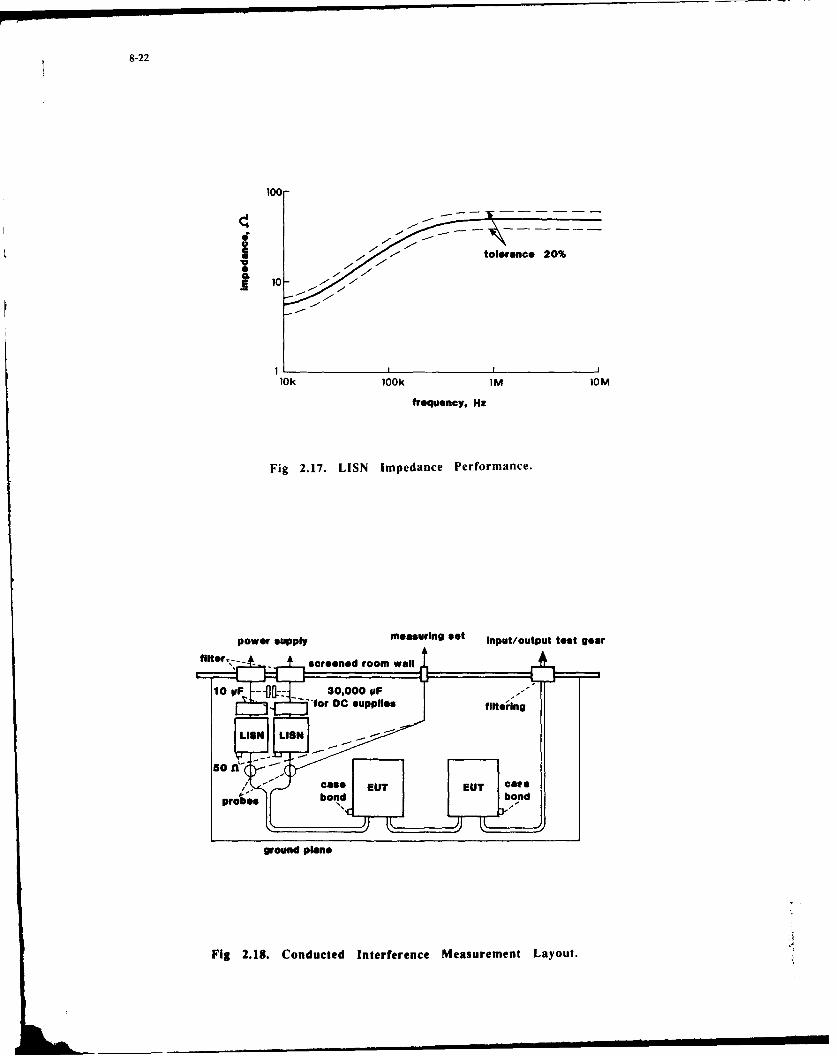
8-22
100-
I tolrance 20%
10k 100k INM 10M
frequency, Hz
Fig 2.17. LJSN Impedance Performance.
power supply measuring set Input/output teot gear
g soud eelnedomwl
Figv 2.18.0 Codce neFeee MauretLyo.

8-23
50
60 -
1 1010 00 00
ula eeiinfrqecH
Fuls 2.0 r epeStion feuny a rwor el
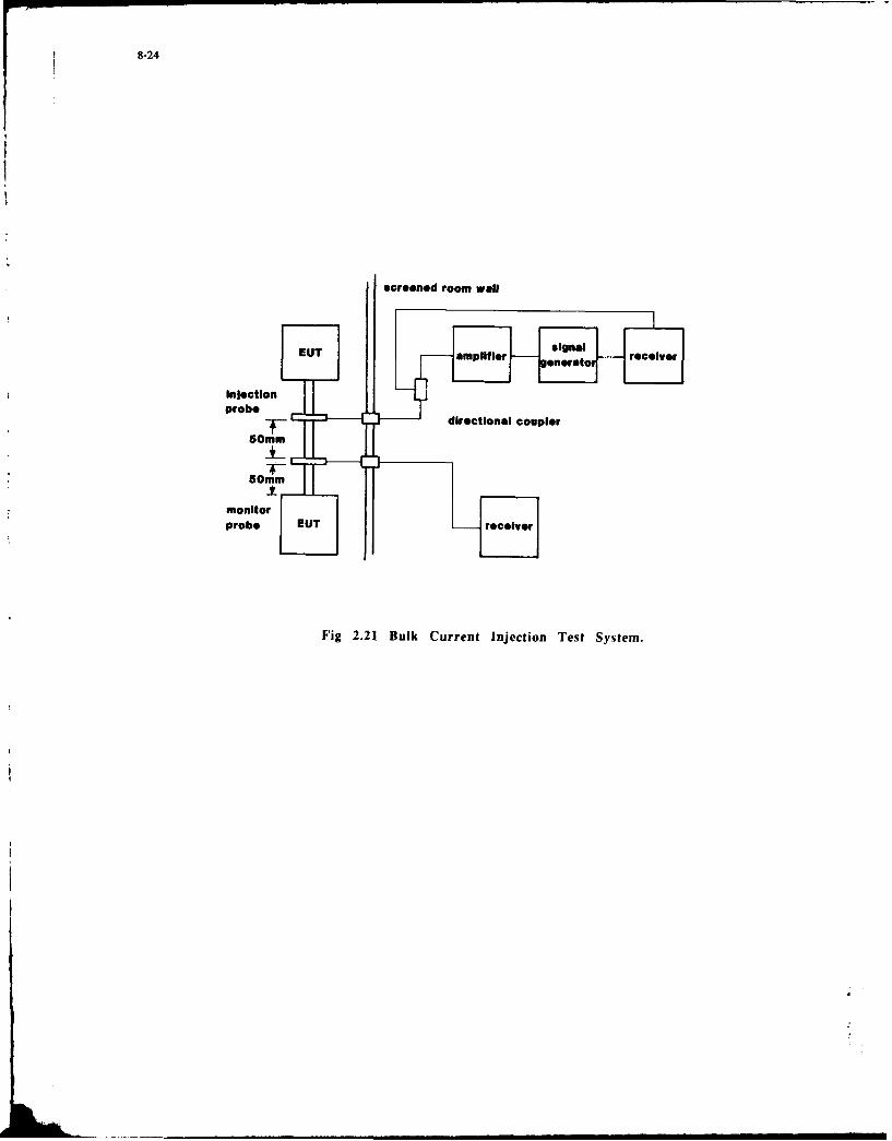
8-24
sereened room wall
probe
monitor
Fig 2.21 Bulk Current Injection Test System.

9-1
Design Principles foreffective ENC.
Prof.ir. J. CatrysseKIH.WV., Zeedijk 101B 8400 Oostende, Belgium
Effective ENC design is directly related on minimising the different effects in ENC : EME, EMS andthe coupling/transmission paths.
A short overview will be given of the most important factors concerned with ENC design. It followsdesign parmeters and design rules for each item.
0. Introduction
Effective ENC design is directly related on to effects may be handled as for a high speed PCB-minimising the effects of some important fadtors design.concerned with NC : emission, susceptibility, As typical parameters, the wavelegth/Dimensionscoupling paths, propagation paths... . At this or the pulse duration/wire length ratios arestage, two remarks mu&L be made : the constants in the general design rules.
a degradatioq in the good working of a In this paper, some general design rules will besystem or circuit is always a cumulative discussed in this manner, so that they may beeffect of noise and interfering signals applied for each appropiated design in real life.(unwanted signals). Without any interfe-rence, a normal design is made for anacceptable Signal/Noise value (S/N), with i. General overviewN - the inherent system noise (bandwidth-limited white noise) for analogue systems/ It has been mantionned that the overall INClirmits wand wih f anaoge systemsy quality of a system is a cumulative effect of acircuits andor itN- the noise io ity lot of items, also internally of a system or alevel or the noise margin for logic PCB, because f.ex. at PCB-level or back-phase
With an interfering ambient, the inter- level, small circuits or components may also befering signals I are added to the (also) regarded as "a system or subsystem".feringsded to te (An overview is summarized in the next table,unwanted noise N. and each point will be discussed in more detail:So the real signal/noise ratio becomes :
S common impedance coupling between systemsS/N - S/N+I T- -IN o common mode coupling to EM-fields
"Icoupling of ground noise into the systems/It is necessary that I/N < I into obtain circuitsa non-disturbed system by interference, differential mode coupling to EM-fieldsbut achieving I/N «< I gives a costly * balanced/unbalanced systems and twisted pairsoverdesign. filtering of power lines
o filtering of data/signal cablesAs a system, it should be understood as 0 crosstalk on wiLesany combination of two or more systems, * reflections on wiressubassemblies, racks, PCB's or even shieldingchips on a PCB for high speed/high fre- decoupling capacitorsquency circuits. sde protection
o non-linear effects and HF behaviour ofcomponents
Pss go .eiCApsA,6s. spectrum management* mechanical design and lay-out
sys 6 TomTwo points should be mentionned
1.1. Reciprocity of emission/susceptibility
The reciprocity theorem is a very general theoremin circuit theory. For EMC, it means that a loopwill act with exactly in the same manner foremission and susceptibility. The same may be saidfor the bandwidth of a system (even a logic one).This means that & good design for susceptibilitywill also have a good behaviour with a low emis-sion level. EMI-sources are always possible EMS-receivers, and vice versa.In practice however, it is more difficult tohave a high EMS-value, due to the fact that foremission control, the choice of components,
igs. 0.1 Schematic of a system. circuits, PCB-lay-out, ... is fully under controlof the designer, but that for imunity control,the noisy ambient is NEVER exactly known in detail.
This means that for some topics, very So, normally in practice, the real problem is ageneral design rules my be given. Ex- design for a good SUSCEPTIBILITY of the system.amplee are about grounding, crosstalk, But, measurements and validation of a system arefield-to-loop/loop-to-field coupling, easier for EMISSION.... for large systems or PCB-design.The only difference is that the largerthe system is, the lower the frequen-cis wherea som effects occur. Thismeans in practice that for a large
computer system, the same rules and
i hL

1.2. Source/victim/coupling path control 2.1. Common impedance coupling.
Control of EHC may be done at different levels Common impedance coupling is the effect thatof the DMC transmission path at the source level, currents from different circuits or compo-victim level or at the level of the coupling nents are flowing through the same conductor,path. creating unwanted voltage drape over this
common wire. Examples are sketched in/-'---" fig. 2.,. .
end
Sce Pc-board
Source Reeiver
COUPLUUPATh
Fig. 1.1. E4C transmission path
At the source and victim level, two worlds of PCB-example (lay-out)design are concerned with :
* the electrical/electronical one, concer-ning the choice of components, circuitdesign, technology, subassemblies, fre-quency, range,..
• the mechanical one, concerning the choiceof PCB-system (ex. double side or multi-layer), lay-out on PCB, mechanical con-struction, mechanical attachment ofcables, .
(D Circuit-example (op-amp design)
ID R I
Fig. 1.2. EHC-levels of a system. 2k Z3
At the coupling and transmission path itself, A ioit is more concerned with mechanical proper-ties and choices, such as boxes and housing,
connectors, filter mountings, cable mounting, Vrack mounting of PCB's, ... 2 R2
A good EMC designed system has been care- 2fully designed at all three points (source,
receiver, path) of a "system".
2. 15 points to remember about EMC design. Fig. 2.1. Examples of common impedance.
As mentionned in another paper of this lectureIn this section, the previous wentionned 15 series, a wire or track on a PCB has not onlyitems will be discussed in some more detail, a resistance, but also P, inductance. The latterwith the links to the ENC-noise balance in one may be estimated as I ni/m.the system and the typical parameters con- Here is an induction LAU - 250 nH.cerned with to minimise RK problems. In the case of TTL logic, a positive going edgeAs stated in the introduction, it is impor- on Z1/0 1 can provide upto 10 nA in 10 osec.tent to minimise the interfering signal So, a voltage VAB is induced over LAB.level I compared with the own noise level Nof the system considered. In this way of - 0thinking, signals I stands for all unwanted V £ - 250.10 101 250m Volt.signals in a system this may be the am- IA AB At 10.10-"hient no!s coupling into part of a circuit,but also reflections on a transmission linedue to mismatch of a load.

9-3
Added to some other minor effects, this vol- Rules 1. Don't use high speed (large At/Attage can cause a false triggening of the values) or large bandwidth (highcircuit 02. When ESD effects are concerned with, frequency swings) for the "sources"even without direct effect on the components, if there is no real need to do it.this voltage drop due to the discharge current 2. Don't mix ground and power supplyflowing through some common impedance of the lines for different cir uits orsystem will cause a bad working of the system. critical parts of it.(Remember for ESD : A/At- IA/10 nsec). Don't mix (sensitive) anlo; and
An equivalent circuit diagram for a comon (high speed) logic circuiting.impedance coupling was given in the figure 3. Don't clean-up circuit lay-out by2.1.1. combining the latest residues ofIt is easily found that gates, flipflops,... of different
% zk circuit parts together in one
V2 1 (V2- s ak V1package.Ia + (R,+ lRa )Zk BE AWARE OF AUTOMATIC CAD LAY-OUT I
The voltage V21 is reduced by reducing the 2.2. Common mode couplingcomon impedance Zk. Normally, circuit-designers and layout-designers (PCB/mechani- As referenced in fig. 2.2.1., comen mode andcal) are working in different departments, differential mode working of a system is direct-without any direct supervision officer. For ly related to the paths currents are flowingthe case of common impedance, a very impor- through.tant problem is the ground-reference, nearlynever drown on logic schematics. Some examples '' aof good and bad design are shown infig. 2.1.2.
VS.
ARA no 1 711"COMMN 01006-4. --t I N VO
Fig. 2.2.1. Common/Differential mode.
It should be stated very clearly that the dif-
BETTER ference between both modes has to do with the+5V currents mentionned. This means that for one
current path, the system may act as a DM system,and for an induced current path, the system isacting as a CM system. Most common more effectshave to do with "a" ground or earth reference,somewhere in the system. Examples are given in
Analog 'fig. 2.2.2.
I OV Logic
g , 2.1. les of
t: . .
?ig. 2.1.2. Examples of common impedace. Fig. 2.2.2. Examples of CM4 in practice.
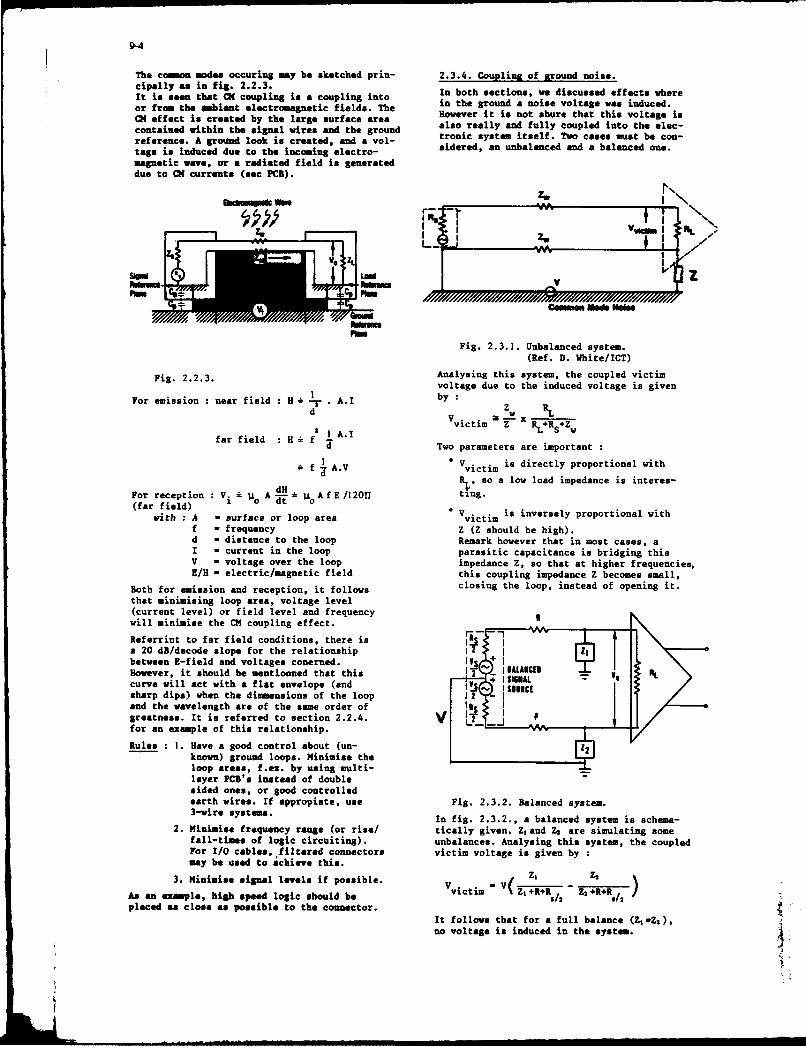
9-4
The coma modes occuring may be sketched prin- 2.3.4. Coupling of ground noise.cipally as in fig. 2.2.3. In both sections, we discussed effects whereIt is &*en that C4 couplings a coupling intosor from the abient electromagnetic fields. The in the ground a noise voltage was induced.CH effect ia created by the large surface area However it is not shure that this voltage iscontained within the signal wires and the ground also really and fully coupled into the elec-reference. A ground look is created, and a vol- tronic system itself. Two cases must be con-
tage is induced due to the incoming electro- sidered, an unbalanced and a balanced one.
magnetic wave, or a radiated field is generateddue to CM currents (sec PCB).
Fig. 2.3.1. Unbalanced system.
(Ref. D. White/ICT)
Pig. 2.2.3. Analysing this system, the coupled victimvoltage due to the induced voltage is given
For emission : near field : H -" . A.I by:d Z W
2 ~A.Ivictim Z U- R+Rs+Zw
fadil T 1wo parameters are important:
A.V V. ct. is directly proportional with
RLso a low load impedance is interes-dHFor reception : V. ' I= i A- loA fE/120l ting.(far field) 0 dtV..iineslprpronlwhwAth A = surface or loop area Vvctm i
f - frequency Z (Z should be high).d - distance to the loop Remark however that in moat cases, aI - current in the loop parasitic capacitance is bridging thisV - voltage over the loop impedance 1, so that at higher frequencies,K/U - electric/magsnetic field this coupling impedance Z becomes small,
Both for emission and reception, it follows closing the loop, instead of opening it.that minimising loop area, voltage level
(current level) or field level and frequencywill mini.ise the CM coupling effect.
Rvferrint to far field conditions, there is I
• 20en fi/elode p for the relationshipS emissio and voltage conered. b :
However, it should be mantionned that this )y" I IALAIB[OIcurve will act with a flat envelope (and ,V, I SAAL -- Isharp dips) when the diamensions of the loop -,I[ !2 - Is 1Cand the wavelength are of the same order ofgreatness. It is referred to section 2.2.4. V i .m '
for an example of this relationship. -r--
Rules: I. Have a good control about (un- r 2known) ground loops. Minimise the
~~loop areas, f.ex. by using multi- -layer PCs' instead of doublesided ones, or good controlledearth wires. If appropiate, use Fig. 2.3.2. Balanced system.3-wire systes. In fig. 2.3.2., a balanced system is schea-
2. Minimi-s frequency range (or rise/ tically given. Z hgand Z are simulating somefall tIes of logic circuiting). unbalances. Analysin this system, the coupledFor -/O cables, filtered connectors victim voltage is given by :may he used to achieve this.
3. Miniis l ignal levels if possible. V( Z, - ZAs an et le, high ieed logic should be Vvictim- Z1 +R+R5 /2 Z2 +R+R,, 2 /placed as close as possible to the connector.
It follows that for a full balance (Z,Z),no voltage is induced in the system. NL
Howver itsol emnine htti INV

9-5
Rule.s I. Use a balanced (or symmetrical) 2. Hinimising frequency range orsystem (and even 3-wire cables) rise/fall times
2. Otherwise, open the ground loop by: 3. Shielding of the DM-wires.
* floating systems, boxes, PCB's* isolating systems (transformers, 2.5. Coupling of DM signals.
opto-isolators,...) Induced UM signals are directly coupled intoSfeed-thru capacitors to pass a system, in the same way as the signals or
wires into a box data. This means that the only way of acting
Be aware for safety earth connections! is to minimise the DM coupling itself. Thebest action to take is to use twisted pair
3. Low impedance design at load level, cables, so that even induced voltages areand high impedance design at source cancelled, due to the opposite loop-direc-level (a current loopsl) tions. A twisted pair is sketched in fig.2.5.1
2.4. Differential mode coupling.
Referring to section 2.2., there is no physical 0.o0o0Q0.0restriction why for the differential mode (DM)there should be no radiated field or no suscep-tibility from incoming fields. However, the loopareas concerned with are much smaller. This isschematically shown in fig. 2.4.1.
Fig. 2.5.1 Twisted pair
An apropiated use of twisted pair cables, with
W M. respect to the same configuration with normalparallel wires gives easily a gain of - 40 upto60 dB of less coupling for DM problems.Better is to use shielded twisted pair cables.It should also be mentionned that a lot ofloops are introduced in a design by currents
flowing through a set of conductors. Examplesare given in fig. 2.5.2., with loops createdby a (bad) power supply/ground reference design,and by connecting larger systems together.
.// For the later case, couples of wires are forminga kind of folded dipole. When the length becomescomparable with the half-wavelength of thefrequency components of a complex signal, very
Fig. 2.4.1. Differential mode coupling, efficient E-field antenna's are created !
The coupling from an incoming plane wave Rules : 1. Minimise the coupling itself byelectrical field into an induced voltage in minimising loop area (twisted pair)a loop with dimensions Ixs is given in and shielding.fig. 2.4.2. 2. Use feed-chru capacitors to pass
wires into a box.V 3 Of MN30O f 0 106Ist 3 MWu
-0 3. Be aware of the existance of wire--40 like, dipole and folded-dipole
antenna-models.
- 2.6. Filtering of power lines.
The difference between power line filtering
-u and data-line filtering is the separation of- the frequency ranges in the spectrum.
For normal situations, filtering power linesis much easier. Typical line-filters are
e am W. an so-wm s in fig. 2.6.
-nw 'to -F L11111:
F ig. 2.4.2. DM coupling i-field/loop voltage I(ref. D. Vhite/ICT) U
The only difference with the coupling of fields min a 01-systems is the loop area, so, in prac-tic. C-coupling is normally the dominant one. low i / .",
Rules I. Minimising the loop area by control- , - ,ling the separation distance between ,. -
wires and using twisted pairs 011(sec. 2.5)
Fig. 2.5.2.

9-6
Rules 1. Make a choice of power line filters,taking into account impedance levels,
- - currents and leakage currents.
2. Proper mounting of the filter in thesystem.
2.7. Filtering of data/signal lines.
For the filtering of data/signal lines, in alot of cases, interfering and useful signalsare in the same frequency-range. It follows that
o o filtering will be a hard job, invoking filteri a7 theory. Examples of the principal filter circuits
? , are given in fig. 2.7.1.T' I= V n O
L
-C ITI"=
Fig. 2.6.1. Power line filters.
There are three points to mention in orderto make a good choice : L L
All normal rules concerning source andload impedances from circuit theory mustC C Lbe used, choosing filters with series or Tshunt branches at their input/outputsections. It should be noted that theinput section for emission is the output Fig. 2.7.1. Basic filter components.
section for susceptibility I In fact, all kind of filter types may be usedCharacteristics and specifications from (ex. Butterworth, Elliptic,...) in order todata sheets are taken for a 50 Qsource/ obtain good filtering characteristics.500 load impedance. So, no one of the For more common cases, some simple tricks maypublished characteristics may be direct- be used, such as the use of ferrite beads.ly used for normal power line applica- These are highly inductive rings, which may betions! placed over wires, PCB-tracks, included in
Look out for the saturation of the cores connectors, ...of the inductances by the current. Fig. 2.7.2. gives some examples of the appli-Look out for the leage currents fro cation of these ferrites, for CM and DIM couplingthe power wires to the neutral/earth wire. of signals. For separating DM signals from
interfering CM signals, a ferrite ring may be
Make a carefull mechanical mounting of placed over both wires.the filter, avoiding unfiltered wirespassing over filtered ones, or creating 0 _ -- --radiating loops inside of a system.This is illustrated in fig. 2.6.2.
urns
I jai iiiI IJ - I 000I1, it
S0 1.. 0
NOISE-- --- 'NOISE
-SGNL % SIGNAL
rig. 2.6.2. Mounting of power line filter.
Fig. 2.7.2. Ferrite beads.

9-7
For DH-signals, of which both wires are pas- As allready mentionned earlier, filtering ofsing through one ring, no flux is generated cables may be used to avoid interfering signalsand the signals are not affected. coming into a system (susceptibility), but alsoSo, in this way it is possible to separate to reduce radiation from loops (emission).OH from C1 signals. Rules : I. Use specially designed filters forIn fig. 2.7.3., the mounting of (filtered) special applications.connectors is shown, creating a ground loopinside of the system (bad) or giving a good 2. Use standard ferrites for simple andshielding effect (good). small dimension applications.
3. Filters, filtered connectors,...should be mounted properly.
2.8. Crosstalk.
For crosstalk discussion, it is assumed herethat a low frequency model will be used. How-ever, basic characteristics of crosstalk are
/obtained obtained, and some general conclusions are
- m s -,m ~ll Fez?
cc C
m9p1 9 2
Fig. 2,7.3. Mounting of connectors. Fig. 2.8.1. Crosstalk of two wires.
In figure 2.7.4,, the construction of filtered The coupling of two adjacent wires or PCB-pins in connectors is shown, tracks can be modelled by the following modes:
a capacitive and an inductive coupling. They areanalysed as follows:
R a
Vqj Ll 92L2
Fig. 2.8.2. Capacitive crosstalk.
It is easily seen that the coupling is given by
V = sC1 2 .R/2
i~ j I+ 2 (C 2 + C2 A)This acts as a high-pass filter. Three importantparameters are concerned with :
frequency (or the derivative of the voltagewaveform)
coupling capacitor C12
large value of the capacitor C2 A, invokingthe influence of a closely coupled ground-plane.
It should also be noted that the capacitivecoupling gives the same coupling voltage at bothends of the victim wire.
Fig. 2.7.4. Filtered connectorsh

9-8
2.9. Reflections.
The interconnection of digital circuits andL 1 Nil__R. databus systems takes an important place in
0system-design of modern electronic equipment.
(t) (1 Two typical examples are shown in the nextv0 L
1 figure 2.9.1.
F 2 1 a oi ane2ieTasiso ~t 142
A, 1-1einhitt s:: v ..... T
(b) Datea S or Porty-Lns Sst-
Fig. 2.8.3. Inductive coupling. Wave or ty Seceiver in
For the inductive coupling part of the cross- Strobs Strobestalk, the circuit of fig. 2.8.3. may be usedfor analysing it. It follows F_ _
a I 2 It Inhibits- Driver 1vV 0 14 << Ro 2 R Fig. 2.9.1. Examples of "long-lines".
a L22 R IR It follows that some transmission line effects1 . L R must be considered. This means that X/l < 20
or t . /T < 10 will give raise to standing
This acts as a high pass filter. Three impor- wave pr terns, reflected power and impedancetant parameters are concerned with : mismatches. In the time domain, reflection
o frequency (or the derivative of the may introduce "ghost" bits, generating false
current waveform) triggering of a circuit.Graphical methods are used, such as Smith
* coupling mutual inductance M12 , influ- chart, time/distance chart and Bergeron chartsenced by a closely coupled ground plane (allowing non-linear loads).level of current, invoking the impedance Depending on the ratio of load and characte-levels at source and load sides. ristic impedances, an extra propagation delay
or ringing on a line is generated. An example
It should be noted that the inductive coupling is shown in the picture of fig. 2.9.2.gives an opposite phase coupled voltage atboth ends of the victim wire.Combining both effects, it follows that thenear end crosstalk (NEXT) ann the far endcrosstalk (FEXT) are not identical. An exam-ple is shown in fig. 2.8.4.
t e 4a. S
54W, Lg C s- . Fig. 2.9.2. Example of ringing due to
,f SOMO line-reflections.
Three parameters are involved with this effect:
Fig. 2.8.4. Example of crosstalk. 0 Characteristic impedance of the line.
Rules 1. Use a closely coupled ground Source output impedance.
reference (plane). o Load input impedance.
Multilayer PCB's are giving a big Altering these impedances may chr'-ge theadvantage for minimising crosstalk. observed effects. Matching the source impedance
2. Use a good separation between is normally done by putting a resistor in serial
critical signal wires, with the source output. Matching the load is
A good example is the isolation obtained by putting shunt resistors between the
given by altering signals and signal line and the ground/power supply wires.Also clamping diodes are used, avoiding the
ground in flat cables and connectors, generation of reflections. It follows also
3. Don't use high frequency speed tech- that any changement of the characteristic im-
nololy if it is not really required pedance will introduce some "reflection-like"by the system. noise.
Examples are corners in PCB tracks, transi-tions in connectors, cable/connector/PCB trin-sitions, pins of IC packages, via's in multi-layer PCB's,

9-9
Rules I. Buslike structures must be matched However, a lot of other (degrading) effectsat their ends. are coming in with the application of real
2. Be aware of any sharp transition in boxes sa transmission line-like signal path. joining structures between two parts ofa box.
3. Make a carefull choice of connectors * joining structures between box and otherfor high speed/high frequency cir- parts (connectors)cuiting.
4. Use cables, back-planes,... with holes
a known characteristic impedance. displays, switches,For PCB-design, this means that As a basic point should be stated that goodmicrostrip design techniques must shielding is only maintained when a goodbe used, conductive contact is realised througout the
5. When matching loads/sources ..., be whole system. For holes and slots, grids,aware of the EXTRA power consumption meshes, honeycomb conductive structures arecaused by these extra components. used, to create "shielded holes".
Fig. 2.10.3. gives a typical SE characte-2.10. Shielding. ristic for a grid-structure.
Shielding of a system is putting a barrier onthe radiating path of a system : it may be doneto avoid the emission of radiated electro- MF - , W 41 '1magnetic waves, or to avoid the penetration ofincoming waves.rA typical box or housing is sketched in 4 6 ,
fig. 2.10.1.
-h l ... "...;' . .. - 7t '-,j1.7-,.\\:
oinn'
seatnIground Fig. 2.10.3. SE of a grid.(Ref. D. White/ICT)
For joining parts of a system, or clean metalFig. 2.10.1. Example of housing. contacts are used, or gaskets giving a con-
Referring to shielding theory (see another tinuous contact over all the parts. Importanton the long run is the effect of galvanic cor-paper of this lecture series), it follows rosion, degrading the contact impedance over
that the shielding effectiveness value of the system, and as a consequence, a degrada-
tion of the SE of the whole housing or box .material constants ( o, I Global SE is determined by the weakest shielding
* frequency* distance of the source to the shielding point.wall Rules I. Make the exact choice of the
* kind of the source wave ( E or H ). shielding box (and material) refer-ring to the basic characteristics(ex. kind of field, distAnce tosource, ...).
", ' ,, . _ .... ,2. Take care of the joining structures,also on the long run for galvaniccorrosion.
3. Take care of holes, openings,...
Fig. 2.10.2. St for flat materials.
(Ref. D. White/ICT)
-AI

9-10
POWER SUPPLY TRANSITION CURRENT74LS GATE
SPECTrRM MEASURED WITHTEICTilON PROME(TRANS FER UPEDA NE 5) 4
SCALE: tDRWzwAL-uv.;
YUCLMMt& out-of-musrs-gob
Fig. 2.11.1. Current during statetransitions.
By putting a decoupling capacitor nearly a cir-cuit, the high current spikes are retained tothe loop formed by this capacitor and the cir-cuit itself. It follows that the longer wirescoming from the power supply are carrying onlya nearly DC current (with much less radiation).
+5V
A.Decoupling
________________Capacitor
Fig. 2.10.4. Examples of shielding boxesand gaskets,
Go~2.11. Decoupling Capacitors.
When logic circuitry is triggered, change- A Son +5Yment of the stats of the transistors is
going on inside a circuit. It means that a SON 3nHlot of transient currents are created, andthese transient currents are flowing throughthe power supply lines. Two effects are im-portant
the voltage drop over these lines, 3154bn
creating a common impedance effect forother circuits, and a drop of supply cvoltage for the own circuit. LIc0 ,1"i
a high frequency radiation because of thecurrent spikes flowing in the loop created "MRA INSERTIONby the power line and the ground. a .
An example of current during state transi- circit ~ TTItions is given in fig. 2.11.1. PATIf.flC
Plekage (DIP)
Canllpr DIPs Sw
vtic.zutg
fertfcl Ce~lsg~rt eVERICA ISERIO

9-11
0,.) An example of installing such devices is given
t C in fig. 2.12.1.
LONGITUDINAL PROTECTION
I.-'
-0 b 0,.80? OOf -a .0
db 0.4?,? Io.,4.. n1 y0
0 10 03 00000.033 1NFN 1.9501 NFD .9601-05
Fig. 2.11 .2. Decoupling capacitors. TRA NSVERSAL PROTECTION
Three points must be mentionned
Regarding radiation problems, the emplace-ment of the decoupling capacitors must bevery close to the circuits itself (and onefor each ic).
Remember that each strip or lead of I m NFN 49501 NFO 49501-06
equals an inductance of I nH. This meansthat, in combination with the capacitor,a serial LC-oscillating circuit is ob-tained. Over the resonance frequency,the circuit behaves inductivally, so no Fig. 2.12.1. Principle crotection for
decoupling effect is obtained. electrical -r -ress.
The same acts for the decoupling capaci- A wide variety of protecting devices are avai-
tor itself, lable, depending on the range of overvoltage(and energy) concerned with :
In the next table, some typical capacitor . gas tubes and neon ampulesvalues are given. gas diodes
o transzorb
L11 Currest eluireent dV - 20% dt - Decoupling c = non-linear resistors (Varistors)m1iy Cate SvItch Gate olfve of NIL e T a£/(4V/dc) 0 Zener-diodes
ICO I* 1 200 sV 50 s 500 pr metal oxide varistors (HOV's)0 silicon avalanche diodes
rz 1 sa o s 50 ST 10 as 3000 pF o capacitors and RC-snubbers.
5?!? 30 ma 20 MA 60. a So s 2500 PY
S I E U -" 60 ev a ns 25oo py Furtheron, after removing the heavy over-
ZE1402 I A 6 s 20 .v 2 as 700 j voltage with one or more of these devices,filtering, deglitching, ... may be done in the
a Based o fanue of five sates. same way as allready described for normal fil-tering techniques.
Fig. 2.11.4. Table of decoupling capacitors.
Rules : 1. Choose the right value and type r --- -
of capacitor. 1 I -50 (M ARIES)
2. Capacitors must be placed as close IGH VOLTAGE Las possible to the circuits. TRANSIENT iI
3. General card decoupling capacitors P IRANSZ Rmust be doubled by small capacitors FEEFT '/ GAS 010C
at the circuit level.
4. Use distributed types if possible(busbars).
5. Take care during lay-out phase ofputting power supply lines and
ground closely together, and toconnect the capacitors to the rightlinac/wires.
2.12. Surge protection. SUPPLY
Surges are heavy overvoltages on power lines.data cables, connectors, ...They are directly related to conductive pro-bles. They are oviginated from the switching Fig. 2.12.2. Typical protection devices.of heavy loads, coupling into lines and cables In the next figure, an example is given of a goodfrom DI?, lightning, ZSD, .... Depending on installation of the protection devices, on a goodtheir origin, those overvoltages (over elec- grounded plate and as close as possible to thetrical overetress) have an amplitude of 100's incoming wires, avoiding that the overstress spikesupto 1000's of volts, may enter the shielded box.Surge protection is done as close as possible
to their source-incoupling path, or as closeas possible to the incoming path at a system.Protection is done by short-circuiting theovervoltage waveforms on itself (between bothwires) or between wires and ground.

9-12
The effect may be described by
o Protectd V out = A . Vin + B . Vin
2 +
akw Wal or EqulpnwW
Grondd P f V. - V cosc(tin
Even without the demodulation effect of broad-a, cast in signals (or pulse modulated carrier of
a radarsystem) another effect occurs
81POWV ot'A.V cosw t
Diod. +B - (1 + cos 2wt)
Te SC w kw This shows that harmonic frequencies are gene-ou Screwrated, and also that a DC-shift (of the bias-
current) is generated.The latter influences internally the goodworking of components and integrated circuits.This is shown in fig. 2.13.2. for a diode-circuit.
dc~h IA)Fig. 2.12.3. Installation of protection
device(Ref. D. White/ICT).
Rules I. Choose one/more appropiated devices,depending on the overvoltage level (SIand spike duration.
2. Mounting of the devices as closeas possible to the incoming wires. 1 ,
3. Avoid that disturbed wires arereally entering the system. meI
[A)2.13. Non-linear effects and HF-behaviour. //The first effect to be mentionned is con-cerning the HF-behaviour of components. 14lIt should be clearly understood that : (B
° each lead has an inductance of I n H/m ..
o everywhere there are two conductors,parasitic capacitances exist.
So, all components have a rather coplex Fig. 2.13.2. DC-shift of diode-circuit due
behaviour at higher frequencies. to H demodulation.
Non-linear effects are the effects of demo- Rule : Avoid that H-signals may enter the com-
dulation of LF signals modulated on H- ponents by short-circuiting the incomingcarriers. This occurs because of the non- paths, as close as possible to the com-
linear behaviour of pn-junctions in diodes, ponent-leads.
transistors, ...There is only one method to avoid this effect: 2.14. Spectru manaeent.short-incuiting for the unwanted HF signals Spectrum management is the technique to avoid-the incoming path to the components. by a good choice of carrier frequencies forExamples of these techniques are shown in telecom systems, local oscillators, ... thatfig. 2.13.1. interferences are created at the beginning of
the concept of electronic systems.
sbettIt is referred to another paper of this lectureseries for more details concerning techniques.
2.15. Mechanical design and lay-out.
Good EMC design of a global system is directlydepending on both good electronic circuit design,
C *! Cu+Cs ll f, ls + ea and on the final mechanical design, construction
and system/PCB-layout. Examples were allreadymentionned in the previous sections handlingabout C4/DM coupling with electromagnetic fields,shielding, crosstalk ... . Layout and designrules were given concerning separation of wires,ground plane references, ....'In this section, some other examples will be
.shown about mechanical design and system layout.
Fig.2.13.1 Avoiding HP signals to enter components.

9-13
But first of all, it should be stated veryclearly that even the best electronic circuit Low Frequencydesign and system concept will act only on its and Low-Speed Logicoptimal level if a good mechanical designand/or layout has been done.Two important points mat be mentionned Medium Frequency
* It is a basic requirement that the system and edium-Speed Logicdesign engineer is supervising both elec-tronic and mechanical design.i Hgh Frequency
* Concerning PCI-layout, use automatic CAD- and High-Speedrouters only for simple and/or non-critical Logicparts of the circuits, but start with the --critical paths by a computer-assisted,but manual routing.The same rule acts if automatic CAD-routersare putting long connection tracks for Fig. 2.15.2. Component placement on PCB.rather simple connection paths.The reason-is that automatic CAD-routers A third example shows a bad and a better layoutare working very carefully, consequently of the power-supply/ground return distributionfollowing the rules of the algorithm, but on a PCB.
they are NOT really thinking I
As a first example, multilayer PCB conceptsare shown. Typical is the close coupling ofpower supply/ground plane reference.
Z -I
A Bad Layout Giving High InductancesMect 1 and Few Adjacent Signal Return Paths, Which Leads
SEeCi 2 em To Crosstalk.
. 1 oa sil5Cg's 3F C m:
LOEMmo SnEMC 0: MI~ M
Fig. 2.15.1. Some multilayer PCB's.
A second example concerns the placement ofcomponents on a PCB. High frequency and high - Better Layoutspeed logic circuitry should be placed as Reduce Power Distribution and Logic-Returnclose as possible to the connector edge. This Impedances, Tra.e Crosstalk and Board Radiation.arrangement minimises the radiation of thePCB, because the loops concerned with thesehigh frequencies are as small as possible.
Fig. 2.15.3. Power distribution on PCB(ref. D. White/ICT).
The fourth examples shows a bad and a bettermounting and coupling of interconnection cables,showing also the famous "pig tail", creatinga loop inside of shielded systems.
t -I.

9-14
(Foam Spaced
0 0 Connectors
Filter Moutnlow fmmSurface Bonded To
Le" C~e Sheld /0 Bulkhead
Outid
Fig.~~ 2.54 Hntn ofna cables.
Fgve of1.4 genralsytemg dfces .PwrCnrle
----------------- 1
OTO~1O~ m5LA'S a--
Pint.-
1OW Li1EL AMlOG AMK.,FC
- - ---------------I LoW LEVEL .0400 ... IRS
; I -I. . . OPN
LO I. ANALOG #APR CIWCU~rs V
POWER VFig. 2.15.5. General system design examples.POPIPO ,(ref. D. White/ICT).
Rules 1. Mlake a very carefull mechanical design,taking into account wire separation,ground reference, pig-tails,..I
VrMVML2. A global supervision is needed for bothelectronical and mechanical design bythe system design engineer.
3. Ieavare of AUTOMATIC CAD-routers for PCB-
out

9-15
3. How To Tackle EMI-problems ? 3.1.7. Other-features ?
In this section, some rules for good shielding - air-cooling filterspractice will be discussed. - optically transparent
- anti-dust sealing- air-pressure sealing
3.1. Bow to tackle the problem ? - oil-leakage
I. Define the type of DEI-signal - moisture exclusion2. Define the type of the problem (R or C) - shock-proof3. Choose the solution : EMT, E4S or shielding/ - temperature range
filtering - fixation (see also galvanic corrosion)4. Have an idea of the signal levels5. Localise the real problem 3.1.8. Choice of salution6. Is there also an ESD problem ?7. Other features needed ? - redesign of the electronic system8. Choice of solutions and materials - choice of components9. (Re)design - power line filters
10. TEST AGAIN I - shielded/filtered connectors- box/enclosure for a whole system
We will discuss these 10 points now more in - shielding the source-circuit or the sensitivedetail. circuit only
- hole slot shielding by : cut-off wave guide
3.1.1. Define the type of EMI-signal gasketsseals
- what is the frequency-range/frequency-band - interconnections of systems by coding of- is it a small-band/broadband signal signals (double) shielded cables twisted/- what is disturbed : a system, a circuit,.., balanced wires.- in what application field (industrial,
consumer,...) 3.1.9. Redesign of the3.1.2. Define the type of the problem: Is an EMI-redesign possible, without redesigning
the whole system (mechanically compatible) ?
- conduction or radiation- intersystem or intrasystem 3.1.10. Test aain and .._- is the source natural or man-made- is it in the near-field/far field region
of the source- E-field or H-field problem
3.1.3. Solution? THINK ALWAYS- Redesign : in many cases, a good redesign
(e.g. PCB's) might resolve the problem,in order to minimise the emission levelitself, or the susceptibility level.
- EII : shielding to avoid that an EMI-signalmay leave a system. (see CE-regulations).This solution is not suitable for naturaland intentionally man-made EMI-sources.
- EMS shielding the "receiver" against EMdisturbing signals.
3.1.4. Sigal levels :References
- what is the signal-level (or field-strenght) of the EMI-signals I Ott, H., Noise reduction in electronic
streght oftheD~lsigalssystems, J. Wiley (1976)
- what is the sensitivity-level (suscepti- 2 yser, . ile s o CAt6u
bility) of the receiving system or circuit 2 Keyser B. Principles of EMC, Artech House(1!985)
- set requireaents to achieve. 3 White, D., 12 volume slices on EMI/EMS/EMC,
3.1.5. Localise the real problem ICT, Gainesville
4 Catrysse, J., & Sinnaeve A., EMI, a tutorial- component in a circuit. circuit in a system: about sources, design, standards and
design of the system. measurements, KIH.WV, Oostende (1984)
- shielding problem of a whole enclosure 5 Transactions on EMC, Symposium records on
- problem about holes, apertures for displays. LRC, IZEE-press.
Connectors, buttons, doors, cooling-in lots, ...)
- power lime/data cablefiltering.
3.1.6. liD 7 (llectra-stotic #ischae_)
Try to find-out if there should be amy USD-problems. £SD-spata wV camein 3Za-problem.And, =NIE solutions we normally the samkiad of mterials.

REPORT DOCUMENTATION PAGE
1. Recipient's Reference 2. Origliator's Reference 3. Further Reference 4. Security Classificationof Document
AGARD-LS- 177 ISBN 92-835-0620-0 UNCLASSIFIED
5. Originator Advisory Group for Aerospace Research and DevelopmentNorth Atlantic Treaty Organization7 rue Ancelle, 92200 Neuilly sur Seine, France
6. rite ELECTROMAGNETIC INTERFERENCE AND ELECTROMAGNETICCOMPATIBILITY
7. Presented at
8. Author(s)/Editor(s) 9. Date
Various June 1991
10. Author's/Editor's Address 11. Pages
Various 146
12. Distribution Statement This document is distributed in accordance with AGARD
policies and regulations, which are outlined on theback covers of all AGARD publications.
13. Keywords/Descriptors
Design Mathematical modelsElectromagnetic compatibility NATOElectromagnetic interference Test equipmentFrequency allocations
14. Abstract
Two aspects of the current electromagnetic (EM) environment having great significance for NATO systems
are:
(a) electromagnetic interference (EMI) arising from both natural and man-made sources;
(b) electromagnetic compatibility (EMC), i.e. the ability of an EM system to function as specified withoutbeing susceptible to EMI, and without itself generating excessive EM! which would cause other systems tomalfunction.
The Lecture Series will first set EMC in a NATO operational context. Major EMI generation mechanisms willthen be reviewed and their characteristics outlined. The manner in which EMI energy couples into EMsystems will be discussed, together with the analysis and modelling tools available to assist in computing suchinteractions.
Modern EMC testing methods and environments will then be examined and their limitations indicated. Therelationship between NATO and civilian EMC requirements will be examined in the light of the EuropeanCommunity EMC Directive. Consideration will also be given to the problems of spectrum management andconservation as they affect systems intentionally radiating EM energy, e.g. radio, radar, etc.
Finally, dean principles and techniques for EM systems with effective EMC characteristics will be presented.A Round Table Discussion will enable attendees to interact in some detail with the lecturing team.
This material in this publication was assembled to support a Lecture Series under the sponsorship of theElectromagnetic Wave Propagtion Panel of AGAR and the Consultant and E Prowramme ofAGARD presented on 10 to 11 June 1991 in Kjeller, Norway, 13 to 14 June 1991 in Konipwinter (nearBonn) Oermany, and 17to 18 June 1991 in Lisbon, Portugal.

022
Nu
ZI uu u Q :u E-
"Z -5 -L 73
go~~~ ~ ~ ~ ~ -=.r- ; .,i",19 <1
E..U V E' ERp T I-Ep110-x
. ppi W U 22 (- V..9.
C.5
1U2 UC
u u 0
P P.
ps .l

=I
~~:1 .11 u ;Z -
S u
U s, .
o4 ~ U '~ ~.;.~~'~ U4.
-C IN
ILI Q 0, 2BE :3 j U
D- 7.g i .
u 2 C-) 7t
z _ u ( UC zlu .- I
MG : E 201- AgC 0~ a E
.542g v< - g '. -S y < j gn -
irlit 911_____ Ho__LL__ __ r=__L __6__% 10"w - tI I , 1 . _ _ _ _ _ _ _ _ _ _
R UE ANt LU A '100 NFUL Y -SUI(-Sl Ui it'U.) IjsP:11i
I R A ~N( f, ~AAI) NON ('I.A.VSS It F-S
I. je ,w i 4.7 38,5 5 ,99
ILi~ .i'd I A6\( Lk 'I Ln. c ipC~ tli-' pas invnihcc' de coe it iiittiiili pijr I'ineiteiitvi dr (Coiircs ',I,
1itc-1 (C kl( mrj'ii~ i:icrr~~II c i crilcopies atjtiprldt- Ageccc eVnicedont i tm Sii si
[ tN'f RI- sI t: DiIFUISIONNAItI(INAI IX
"I iI NlttFISLAN IA.
)- 75 1, J L!Qeihdcii jj d.h~ 1cvii
I ~irlt'iii~ltur ,(~. ~j3 \4Acroiiliutica Mili~aireIii tm-a~ofit ILI Fowi.* Au~wilic Uffcio del Dlegilto NaimnI: it)~~ A ( iA R
Quiarticr Reine Elisabeth 3 Pliaz~alc AdcnaurRut: dLY %cc. 110 inI)l - 01441 Roima LUlt
\I 1,4\ Ltu )X'NcflJ
I hiucetei ju Service de% Rcvwi esicnienis Siitiut)tBliu
\ptiii'r tic la1 Wle~n~e N.w,!c NOaiiiqicVIne LcgiuI~i~ (lma1rjo K I A IlK2 c)V i
C,,! MARK ,\ithli:iliCc
)~jI Ic1ic R !Adi huc P 0. MIX 25
A ui~ci 4di N-2107 K IccIe
Nei hetand% I Jlegal lii i'A ( AlZI* Natijonal Acrosmce Laboto u \1 NI k
POR"I1 1(iA.
%. ~I.' ISO li de Alt ruiiide
2700~ Aidora
'icfcntitic and 1 echnical t .if-. N~ Milli Savuricia Ihqrkanligi (%NIS )IDckelia Air Force B~ase ARGI I Daire BHuskaniki (ARGI)Dv)elia, A thrns TGA 10 11) Ankara
1 (LiNYRL NA 11( NAI, I: D)I )lRIIJI 10IN DEt'S LTATS-UNIS (N..ASA) NE DETIENT V'AS l*. S F(XK'.1' , 111 -tLtICA I ONS A0ARI) 1:1 LIS DENIANDWS [VLXEMPLAIRIES DOiVENTI E 'RE ADRLSSIA:S t)IRECt"UNt N
AL i SI:RVI' NA]I IONAL TECHNIQUE DiE LINFORMATION 1NTIS) 1)ONT UADRESSIF S1.Y
AGE--NC-S, DE' VtENTE..NatIiinal I echnical Information Service FSA/Information Retrieval serrve I he British ijbrarNN HiS iropean Splice Agency )iucuritn SuppIyll)wuhuoo
52hi Poist Royal Road 10, rue Mario Nikis Boston Spa. Wethcrh%,sptngficld, Virginia 22 161 15;0 15 Paris WVest Y'olkshire I-S23713Q1Fia t%- I. ni% ;,rance Royasume Uni
Let, dcmandes dc microfiches 4I dute phuitiicoplcs de documnents AGARD (y comprisle demandes Waits aupr~sdu wI~~Irv]a denomination AGARD. ain-o que le riunrel e sifie dc I'AGARD (Par exempkc AGARD-AG(3 I) Dsifomlknaal5. cquleI titre el la Jute dc publication sont souhaitables. Vcuillertnter qu ii ya lieu de spifior AGA RD-R-nnn et A(A RD-AR-nt l0ru ,14 1,S
eiommandc tde rapport% AGARI)o et de- rapportseonsultatifs AGA RD) n-.spectivement. Des r~ferencts bitikuraphiques eomi~pt", in,,i I4I
Jes resumulis des publications AGARD figurent dan,. les journnmx sul-vants:Scientiticlue and Tcchnical Ace-ospacc Reports (STAR) Government Reports Announcemenu andi Index (GRA& 1)pnuiliu par lat NASA Scientifioe and Technical pubIIW erlto National Technical Information StromcInformation Division ** iingfielNASA Headquarters (Ntr) Vrii26Waxhingt )n D.C. 20546 ElatirlUnislihits-Unis tacemsble ipaknint cii mtxe Intaitif tbns, ka tesc dt
onies bibliogralshiquos en hign dui KTIS, et --ow Ct)-R(X%1
REPRODUCED FROMB3EST AVAILABLE COPY Inprimi 1%, pr SpdaIlkd NnimS Srren imi d
40 Chigwn hile LON1kIin, tu 1c(;owjrz


![Electromagnetic Field Theory [Chapter[Chapter 4 ...edu.hansung.ac.kr/~kwangho/lectures/EMT/2010_Fall/...Electromagnetic Field Theory [Chapter[Chapter 4: Electrostatic Fields] 4: Electrostatic](https://img.pdfslide.us/doc/110x75/610d249c8745b56c264c1390/electromagnetic-field-theory-chapterchapter-4-edu-kwangholecturesemt2010fall.jpg)