Embed Size (px)
Citation preview
The-Safety-Valve.com
Best AvailabilityLESER Change-over Valves
Type 330, Type 320
2
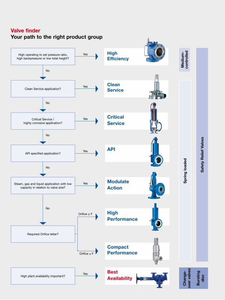
Valve finderYour path to the right product group
High plant availability important?
Required Orifice letter?
No
No
No
No
No
Critical Service
Clean Service
Med
ium
-co
ntro
lled
Cha
nge-
over
val
ves
Bur
stin
g
disc
Sp
ring
load
ed
Saf
ety
Rel
ief
Valv
es
High Performance
API
Modulate Action
High Efficiency
Orifice ≥ F
Steam, gas and liquid application with low capacity in relation to valve size?
API specified application?
Critical Service / highly corrosive application?
Clean Service application?
High operating to set pressure ratio, high backpressure or low total height?
Yes
Yes
Yes
Yes
Yes
Yes
Orifice ≤ F
Compact Performance
Best Availability
3
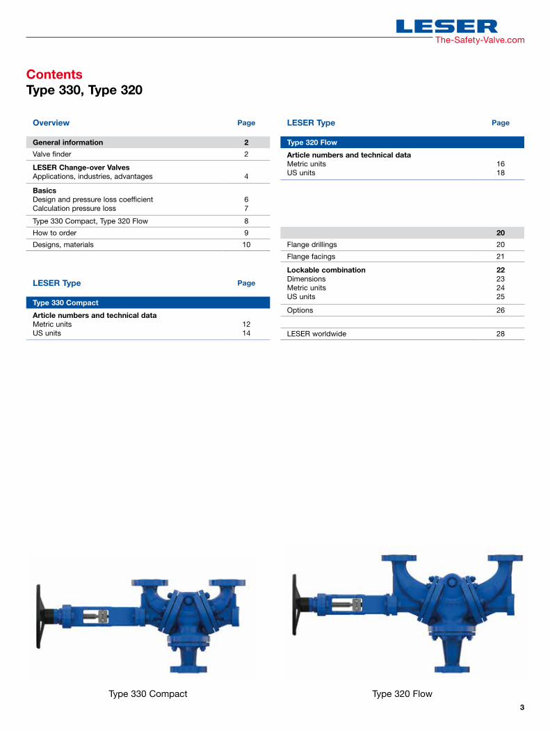
Type 320 FlowType 330 Compact
ContentsType 330, Type 320
Overview Page
General information 2
Valve finder 2
LESER Change-over ValvesApplications, industries, advantages 4
Basics Design and pressure loss coefficientCalculation pressure loss
67
Type 330 Compact, Type 320 Flow 8
How to order 9
Designs, materials 10
20
Flange drillings 20
Flange facings 21
Lockable combinationDimensionsMetric unitsUS units
22232425
Options 26
LESER worldwide 28
LESER Type Page
Type 330 Compact
Article numbers and technical dataMetric unitsUS units
1214
LESER Type Page
Type 320 Flow
Article numbers and technical dataMetric unitsUS units
1618
The-Safety-Valve.com

4
Safety valve side
Piping side
LESER Change-over Valves
Applications Change-over valves are used in various industries in order to ■ ensure uninterrupted operation ■ minimise safety risks due to
unplanned shutdown periods.
These industries are■ Petrochemical industry■ Oil and gas industry■ Technical gasses■ Chemicals industry■ Refrigeration
Safe operation 24/7
– precise pressure loss coefficients for any configuration enable a reliable calculation of the inlet pressure loss
– simple and fail-safe switch-over
– robust and maintenance-free design
Fast availability
– short delivery times synchronised with the safety valves
– complete optimized combination from one supplier
Change-over valves are used to connect two safety valves with a pipe connection to a pressure system, in order to in-crease operational availability. One safety valve is in operation and one safety valve is on standby.
The standby safety valve can be disassembled and serviced, for example during running operation. The pressure system continues to be protected against impermissible pressure. This way, shutdown periods of the plant can be planned inde-pendent of the maintenance cycles of the safety valves.
LESER Change-over Valves – The advantages
Most economic solution
– flow-optimized design for minimal inlet pressure loss
– Type 330 Compact for standard requirements, Type 320 Flow for high requirements of inlet pressure loss
– variable inlet body on the piping side to adjust to existing piping nominal sizes and to reduce the inlet pressure loss
– smart coupling: standardized solution for lockable com-bination with change-over valves of different nominal size and pressure ratings with definite dimensions and precise pressure loss coefficients
5
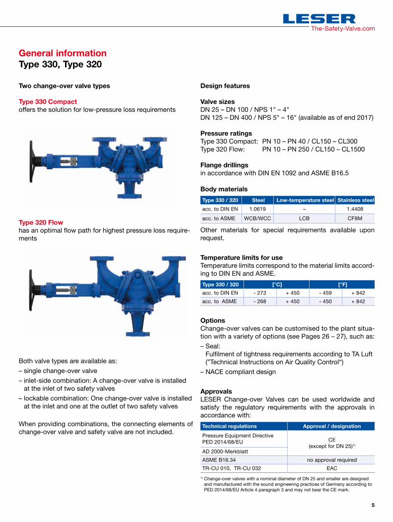
Two change-over valve types
Type 330 Compactoffers the solution for low-pressure loss requirements
Type 320 Flowhas an optimal flow path for highest pressure loss require-ments
Both valve types are available as:– single change-over valve– inlet-side combination: A change-over valve is installed
at the inlet of two safety valves– lockable combination: One change-over valve is installed
at the inlet and one at the outlet of two safety valves When providing combinations, the connecting elements of change-over valve and safety valve are not included.
Design features
Valve sizes DN 25 – DN 100 / NPS 1" – 4" DN 125 – DN 400 / NPS 5" – 16" (available as of end 2017)
Pressure ratings Type 330 Compact: PN 10 – PN 40 / CL150 – CL300Type 320 Flow: PN 10 – PN 250 / CL150 – CL1500
Flange drillings in accordance with DIN EN 1092 and ASME B16.5
Body materials
Type 330 / 320 Steel Low-temperature steel Stainless steel
acc. to DIN EN 1.0619 – 1.4408
acc. to ASME WCB/WCC LCB CF8M
Other materials for special requirements available upon request.
Temperature limits for useTemperature limits correspond to the material limits accord- ing to DIN EN and ASME.
Type 330 / 320 [°C] [°F]
acc. to DIN EN - 273 + 450 - 459 + 842
acc. to ASME - 268 + 450 - 450 + 842
OptionsChange-over valves can be customised to the plant situa-tion with a variety of options (see Pages 26 – 27), such as:– Seal:
Fulfilment of tightness requirements according to TA Luft (”Technical Instructions on Air Quality Control“)
– NACE compliant design
ApprovalsLESER Change-over Valves can be used worldwide and satisfy the regulatory requirements with the approvals in accordance with:
Technical regulations Approval / designation
Pressure Equipment DirectivePED 2014/68/EU CE
(except for DN 25)1)
AD 2000-Merkblatt
ASME B16.34 no approval required
TR-CU 010, TR-CU 032 EAC
1) Change-over valves with a nominal diameter of DN 25 and smaller are designed and manufactured with the sound engineering practices of Germany according to PED 2014/68/EU Article 4 paragraph 3 and may not bear the CE mark.
General informationType 330, Type 320
The-Safety-Valve.com
6
BasicsPressure loss in the inlet line is considered to be the pres-sure difference between the pressure in the system to be safeguarded and the pressure in front of the safety valve during discharge.
When a safety valve is activated, the flow losses in the inlet line cause a pressure loss. The pressure loss in the inlet line may not exceed 3% of the set pressure in accordance with applying international standards. If the 3% limit is exceed-ed, the safety valve may not show a stable function any longer (chatter). As a consequence, the full power may not be discharged and there is a danger of excessive pressure within the system.
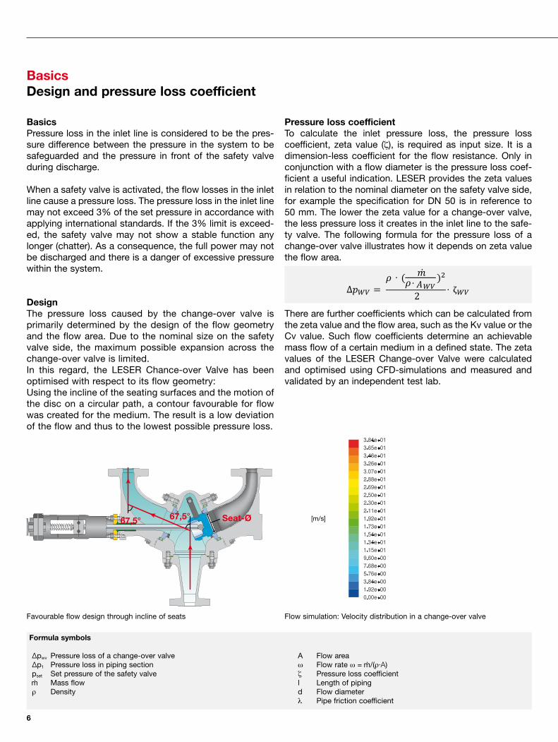
DesignThe pressure loss caused by the change-over valve is primarily determined by the design of the flow geometry and the flow area. Due to the nominal size on the safety valve side, the maximum possible expansion across the change-over valve is limited.In this regard, the LESER Chance-over Valve has been optimised with respect to its flow geometry:Using the incline of the seating surfaces and the motion of the disc on a circular path, a contour favourable for flow was created for the medium. The result is a low deviation of the flow and thus to the lowest possible pressure loss.
Pressure loss coefficientTo calculate the inlet pressure loss, the pressure loss coefficient, zeta value (ζ), is required as input size. It is a dimension-less coefficient for the flow resistance. Only in conjunction with a flow diameter is the pressure loss coef-ficient a useful indication. LESER provides the zeta values in relation to the nominal diameter on the safety valve side, for example the specification for DN 50 is in reference to 50 mm. The lower the zeta value for a change-over valve, the less pressure loss it creates in the inlet line to the safe-ty valve. The following formula for the pressure loss of a change-over valve illustrates how it depends on zeta value the flow area.
There are further coefficients which can be calculated from the zeta value and the flow area, such as the Kv value or the Cv value. Such flow coefficients determine an achievable mass flow of a certain medium in a defined state. The zeta values of the LESER Change-over Valve were calculated and optimised using CFD-simulations and measured and validated by an independent test lab.
Formula symbols
∆pwv Pressure loss of a change-over valve∆p1 Pressure loss in piping sectionpset Set pressure of the safety valve
Mass flowρ Density
A Flow areaω Flow rate ω = /(ρ⋅A) ζ Pressure loss coefficientl Length of pipingd Flow diameterλ Pipe friction coefficient
BasicsDesign and pressure loss coefficient
67,5° 67,5° Seat-Ø
2 ζA
Flow simulation: Velocity distribution in a change-over valveFavourable flow design through incline of seats
[m/s]

7
The-Safety-Valve.com
BasicsCalculation of pressure loss
Piping– all piping sections– separate pressure loss calculation for different flow
diameters– reducers for connecting pipes of different sizes, are
engaged within the installations part Applying this to the selected example results in two sections which create a pressure loss in the inlet line. One section for the change-over valve and one section for the piping piece in a certain nominal size.
It is then checked whether the calculated pressure loss falls under the 3%-criterion.According to applying standards, the 3%-criterion refers to the set pressure. The AD regulations, however, references the 3% to the difference between set pressure and super-imposed backpressure.
Inlet pressure loss exceeding 3% are only permitted in accordance with the standards if the manufacturer is able to confirm the function and performance of the safety valves with higher degrees of pressure loss through trials.
The example selected here represents a normal installation situation. In reality, much more complex installations may occur due to various pipe nominal sizes which make the calculation of pressure loss more difficult.
Calculating pressure loss with VALVESTAR®
VALVESTAR® makes it possible to calculate the pressure loss in the inlet line of the safety valve. In the case of dif-ferent flow areas of the individual sections in the inlet line, the zeta value of the change-over valves must reference a common calculation diameter, which is then used by VALVESTAR® to calculate the pressure loss.
total
total
ζ + total
The general formula for the calculation of pressure loss in pipes is as follows:
There is a difference between a part for installations and a part for piping sections
Installations Piping
Installations– all installations including the change-over valve– standard values for pressure loss coefficients of installa-
tions can be extracted from the applying standards– zeta values of piping components relating to the same
diameter may be added.
= (λtotal
= ∑ζ + λtotal
To calculate the pressure loss in the inlet line to the safety valve entrance, the change-over valve as well as possible addition piping sections and installations must be considered. To do so, the inlet pipe system is divided into sections. A section is formed for each flow or reference diameter.
In the following example, two sections can be formed. One for the change-over valve (∆pwv) and one for the connected piping (∆p1).
p1
I
∆ptotal
d∆p1
∆pwv
p0
8
Type 330
Hextended
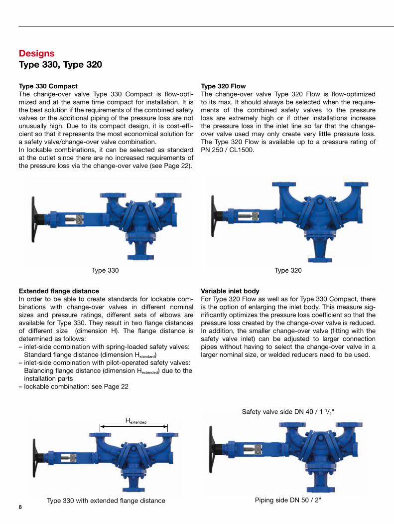
DesignsType 330, Type 320
Type 330 CompactThe change-over valve Type 330 Compact is flow-opti-mized and at the same time compact for installation. It is the best solution if the requirements of the combined safety valves or the additional piping of the pressure loss are not unusually high. Due to its compact design, it is cost-effi-cient so that it represents the most economical solution for a safety valve/change-over valve combination.In lockable combinations, it can be selected as standard at the outlet since there are no increased requirements of the pressure loss via the change-over valve (see Page 22).
Type 320 FlowThe change-over valve Type 320 Flow is flow-optimized to its max. It should always be selected when the require-ments of the combined safety valves to the pressure loss are extremely high or if other installations increase the pressure loss in the inlet line so far that the change-over valve used may only create very little pressure loss. The Type 320 Flow is available up to a pressure rating of PN 250 / CL1500.
Extended flange distanceIn order to be able to create standards for lockable com-binations with change-over valves in different nominal sizes and pressure ratings, different sets of elbows are available for Type 330. They result in two flange distances of different size (dimension H). The flange distance is determined as follows:– inlet-side combination with spring-loaded safety valves:
Standard flange distance (dimension Hstandard)– inlet-side combination with pilot-operated safety valves:
Balancing flange distance (dimension Hextended) due to the installation parts
– lockable combination: see Page 22
Variable inlet bodyFor Type 320 Flow as well as for Type 330 Compact, there is the option of enlarging the inlet body. This measure sig-nificantly optimizes the pressure loss coefficient so that the pressure loss created by the change-over valve is reduced. In addition, the smaller change-over valve (fitting with the safety valve inlet) can be adjusted to larger connection pipes without having to select the change-over valve in a larger nominal size, or welded reducers need to be used.
Type 320
Safety valve side DN 40 / 1 1/2"
Piping side DN 50 / 2"Type 330 with extended flange distance

9
The-Safety-Valve.com
How to OrderType 330, Type 320
Composition of the article number
Order specification
In order to clearly specify a change-over valve, the following information is required:
Base construction
Article number _ _ _ _._ _ _ _
Operating temperature ________ ___ [°C / °F / K ...]
Operating pressure ________ ___ [barg / psig ...]
Body materials Q09 1.0619 / WCB
Q10 LCB
Q11 1.4408 / CF8M
- Other materials _________
Design regulations ASME B16.34 + PED 2014/68/EU
PED 2014/68/EU
ASME B16.34
Connections
Safety valve side
Nominal size DN ________ NPS ________
Pressure rating PN ________ CL ________
Flange facing DIN EN 1092 ________ ASME B16.5 ________
Piping side
Nominal size DN ________ NPS ________
Pressure rating PN ________ CL ________
Flange facing DIN EN 1092 ________ ASME B16.5 ________
Combination
H dimension standard
H dimension extended
Combined safety valves LESER Type _ _ _ _._ _ _ _ others
Lockable combination no yes ➞ Inlet CoV
Outlet CoV
Options
Documentation
0: Global Configuration
001: Counting number (nominal size, pressure rating)
330: Type
0: Configurable base material - Q09: Steel, body material 1.0619 / WCB - Q10: Low-temperature steel, body material LCB - Q11: Stainless steel, body material 1.4408 / CF8M
3300.0010

10
DesignsType 330, Type 320
1.0.26
412 401 405 55 7
204 12 3 5 2 1 60 4
56

11
The-Safety-Valve.com
Materials Type 330, Type 320
Item ComponentSteel Low-temperature steel Stainless steel
Option Code Q09 Q10 Q11
1 Inlet body1.0619 – 1.4408
SA 216 WCB SA 352 LCB SA 351 CF8M
2 Body1.0619 – 1.4408
SA 216 WCB SA 352 LCB SA 351 CF8M
3 Elbows – Activation side
1.0619 – 1.4408SA 216 WCB SA 352 LCB SA 351 CF8M
4 Elbows1.0619 – 1.4408
SA 216 WCB SA 352 LCB SA 351 CF8M
5 Seat
< PN 100 1.4404 1.4404 1.4404 < CL600 316 L 316 L 316 L≥ PN 100 1.4404 stellited 1.4404 stellited 1.4404 stellited≥ CL600 316 L stellited 316 L stellited 316 L stellited
7 Disc
< PN 100 1.4404 1.4404 1.4404< CL600 SA182 316 L SA182 316 L SA182 316 L≥ PN 100 1.4404 stellited 1.4404 stellited 1.4404 stellited≥ CL600 SA182 316L stellited SA182 316L stellited SA182 316L stellited
12 Spindle1.4021 1.4021 1.4404
Chrome steel Chrome steel 316L
204 Packing gland1.4541 / graphite 1.4541 / graphite 1.4541 / graphite
Stainless steel / graphite Stainless steel / graphite Stainless steel / graphite
401 Yoke1.0619 1.0619 1.4408WCB WCB CF8M
405 Position indicating device
1.4408 1.4408 1.4408CF8M CF8M CF8M
412 Hand wheel1.0335 1.0335 1.0335Steel Steel Steel
55 Stud
Design regulations:PED 1.7225 / SA 193 B7 A4-701) A4-701)
ASME 1.7225 / SA 193 B7 A4-70 / B8M1) A4-70 / B8M1)
PED / ASME 1.7225 / SA 193 B7 A4-70 / B8M1) A4-70 / B8M1)
56 NutPED 1.7225 / SA 194 Gr. 7 A4-701) A4-701)
ASME 1.7225 / SA 194 Gr. 7 A4-70 / 8M1) A4-70 / 8M1)
PED / ASME 1.7225 / SA 194 Gr. 7 A4-70 / 8M1) A4-70 / 8M1)
60 GasketGraphite Graphite GraphiteGraphite Graphite Graphite
1) Type 320 DN 80/3" and DN 100 / 4" in PN 250/CL1500: – PED: 1.4980 / Gr. 660B – ASME: Gr. 660B – PED / ASME: 1.4980 / Gr. 660B
Please note– LESER reserves the right to make changes– LESER may use higher quality materials without giving prior notice– Every part can be replaced by other material according to customer specification

12
Type 330 CompactArticle numbers and technical dataMetric units
Safety valve side DN 25 40 50 65 80 100
Art. No. 3300. 0010 0050 0070 0090 0100 0120
Pressure rating body basic construction PN 40
Sta
ndar
d
Piping side DN 25 40 50 65 80 100
Pressure loss coefficient (zeta) [–] 0.56 0.7 0.88 0.7 0.89 0.52
KVS (rt, water) [m³/h] 33 76 107 202 271 555
Dimensions and weights
E1 [mm] 252 242 252 275 275 330
E2 [mm] 160 160 160 245 245 270
C1 [mm] 650 650 650 760 760 816
C2 [mm] 216 244 247 334 344 366
s1) 2) [mm] 26 30 33 35 38 42
W [mm] 250 250 250 250 250 400
H dimension standard [mm] 270 330 330 475 475 475
Weight H dimension standard [kg] 73 78 79 117 125 185
H dimension extended [mm] 330 475 475 560 560
E2 H dimension extended [mm] 180 180 180 265 270
C1 H dimension extended [mm] 650 714 714 760 815
C2 H dimension extended [mm] 230 316 320 386 409
Weight H dimension extended [kg] 74 85 87 125 190
Exp
ansi
on
pip
ing
sid
e
Safety valve side DN 25 40 65
Piping side DN 40 50 80
Pressure loss coefficient (zeta) [–] 0.2 0.51 0.56
KVS (rt, water) [m³/h] 56 90 226
Dimensions and weights
E1 [mm] 242 252 245
s piping side1) 2) [mm] 30 33 38
Weight H dimension standard [kg] 74 78 121
Weight H dimension extended [kg] 75 86 –
Safety valve side DN 25
Piping side DN 50
Pressure loss coefficient (zeta) [–] 0.18
KVS (rt, water) [m³/h] 59
Dimensions and weights
E1 [mm] 252
s piping side1) 2) [mm] 33
Weight H dimension standard [kg] 75
Weight H dimension extended [kg] 76
1) The flange thickness and the outer diameter of the connection flanges may be larger than specified by the norm.2) The dimensions are subject to a casting tolerance of max. ± 5 mm / 3/16 inch.
Available as of end 2017

13
The-Safety-Valve.com
Safety valve side DN 125 150 200 250 300 350 400
Art. No. 3300. 0140 0150 0170 0180 0190 0200 0210
Pressure rating body basic construction PN 40 PN 25 PN 16
Sta
ndar
d
Piping side DN
Pressure loss coefficient (zeta) [–]
KVS (rt, water) [m³/h]
Dimensions and weights
E1 [mm]
E2 [mm]
C1 [mm]
C2 [mm]
s1) 2) [mm]
W [mm]
H dimension standard [mm]
Weight H dimension standard [kg]
H dimension extended [mm]
E2 H dimension extended [mm]
C1 H dimension extended [mm]
C2 H dimension extended [mm]
Weight H dimension extended [kg]
1) The flange thickness and the outer diameter of the connection flanges may be larger than specified by the norm.2) The dimensions are subject to a casting tolerance of max. ± 5 mm / 3/16 inch.
Available as of end 2017
H
W
Required mounting space 200 mm
E2
E1
s
C1 C2s
Safety valve side
Piping side
14
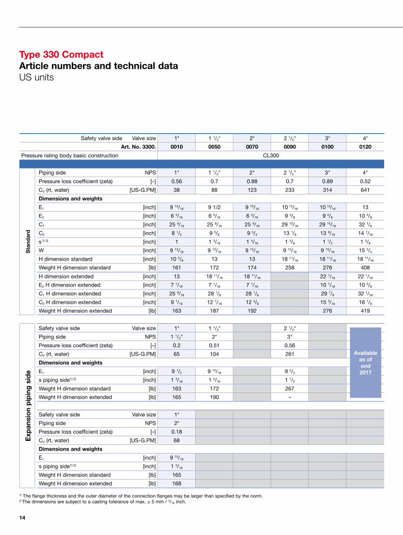
Type 330 CompactArticle numbers and technical dataUS units
Safety valve side Valve size 1" 1 1/2" 2" 2 1/2" 3" 4"
Art. No. 3300. 0010 0050 0070 0090 0100 0120
Pressure rating body basic construction CL300
Sta
ndar
d
Piping side NPS 1" 1 1/2" 2" 2 1/2" 3" 4"
Pressure loss coefficient (zeta) [–] 0.56 0.7 0.88 0.7 0.89 0.52
CV (rt, water) [US-G.PM] 38 88 123 233 314 641
Dimensions and weights
E1 [inch] 9 15/16 9 1/2 9 15/16 10 13/16 10 13/16 13
E2 [inch] 6 5/16 6 5/16 6 5/16 9 5/8 9 5/8 10 5/8
C1 [inch] 25 9/16 25 9/16 25 9/16 29 15/16 29 15/16 32 1/8
C2 [inch] 8 1/2 9 5/8 9 3/4 13 1/8 13 9/16 14 7/16
s1) 2) [inch] 1 1 3/16 1 5/16 1 3/8 1 1/2 1 5/8
W [inch] 9 13/16 9 13/16 9 13/16 9 13/16 9 13/16 15 3/4
H dimension standard [inch] 10 5/8 13 13 18 11/16 18 11/16 18 11/16
Weight H dimension standard [lb] 161 172 174 258 276 408
H dimension extended [inch] 13 18 11/16 18 11/16 22 1/16 22 1/16
E2 H dimension extended [inch] 7 1/16 7 1/16 7 1/16 10 7/16 10 5/8
C1 H dimension extended [inch] 25 9/16 28 1/8 28 1/8 29 7/8 32 1/16
C2 H dimension extended [inch] 9 1/16 12 7/16 12 5/8 15 3/16 16 1/8
Weight H dimension extended [lb] 163 187 192 276 419
Exp
ansi
on
pip
ing
sid
e
Safety valve side Valve size 1" 1 1/2" 2 1/2"
Piping side NPS 1 1/2" 2" 3"
Pressure loss coefficient (zeta) [–] 0.2 0.51 0.56
CV (rt, water) [US-G.PM] 65 104 261
Dimensions and weights
E1 [inch] 9 1/2 9 15/16 9 2/3
s piping side1) 2) [inch] 1 3/16 1 5/16 1 1/2
Weight H dimension standard [lb] 163 172 267
Weight H dimension extended [lb] 165 190 –
Safety valve side Valve size 1"
Piping side NPS 2"
Pressure loss coefficient (zeta) [–] 0.18
CV (rt, water) [US-G.PM] 68
Dimensions and weights
E1 [inch] 9 15/16
s piping side1) 2) [inch] 1 5/16
Weight H dimension standard [lb] 165
Weight H dimension extended [lb] 168
1) The flange thickness and the outer diameter of the connection flanges may be larger than specified by the norm.2) The dimensions are subject to a casting tolerance of max. ± 5 mm / 3/16 inch.
Available as of end 2017

15
The-Safety-Valve.comThe-Safety-Valve.com
Safety valve side Valve size 5" 6" 8" 10" 12" 14" 16"
Art. No. 3300. 0140 0150 0170 0180 0190 0200 0210
Pressure rating body basic construction CL300 CL150 CL150
Sta
ndar
d
Piping side NPS
Pressure loss coefficient (zeta) [–]
CV (rt, water) [US-G.PM]
Dimensions and weights
E1 [inch]
E2 [inch]
C1 [inch]
C2 [inch]
s1) 2) [inch]
W [inch]
H dimension standard [inch]
Weight H dimension standard [lb]
H dimension extended [inch]
E2 H dimension extended [inch]
C1 H dimension extended [inch]
C2 H dimension extended [inch]
Weight H dimension extended [lb]
1) The flange thickness and the outer diameter of the connection flanges may be larger than specified by the norm.2) The dimensions are subject to a casting tolerance of max. ± 5 mm / 3/16 inch.
Available as of end 2017
H
W
Required mounting space 200 mm
E2
E1
s
C1 C2s
Safety valve side
Piping side
16
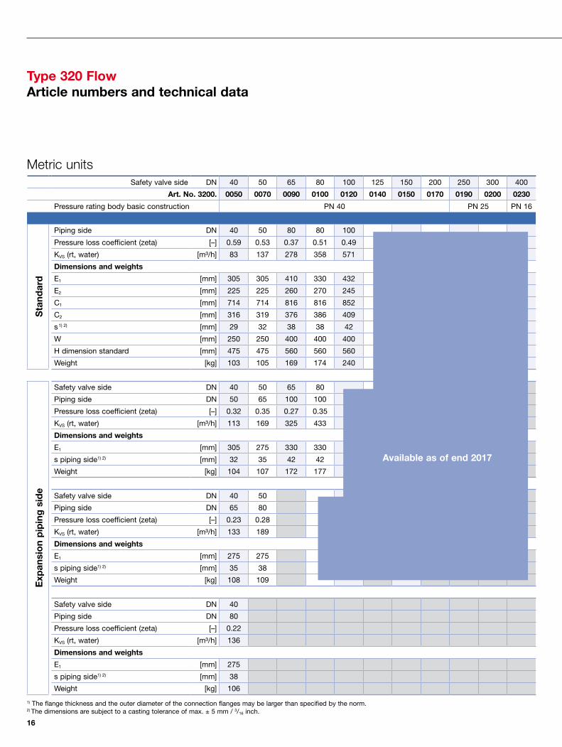
Type 320 FlowArticle numbers and technical data
Metric unitsSafety valve side DN 40 50 65 80 100 125 150 200 250 300 400
Art. No. 3200. 0050 0070 0090 0100 0120 0140 0150 0170 0190 0200 0230
Pressure rating body basic construction PN 40 PN 25 PN 16
Sta
ndar
d
Piping side DN 40 50 80 80 100
Pressure loss coefficient (zeta) [–] 0.59 0.53 0.37 0.51 0.49
KVS (rt, water) [m³/h] 83 137 278 358 571
Dimensions and weights
E1 [mm] 305 305 410 330 432
E2 [mm] 225 225 260 270 245
C1 [mm] 714 714 816 816 852
C2 [mm] 316 319 376 386 409
s1) 2) [mm] 29 32 38 38 42
W [mm] 250 250 400 400 400
H dimension standard [mm] 475 475 560 560 560
Weight [kg] 103 105 169 174 240
Exp
ansi
on
pip
ing
sid
e
Safety valve side DN 40 50 65 80
Piping side DN 50 65 100 100
Pressure loss coefficient (zeta) [–] 0.32 0.35 0.27 0.35
KVS (rt, water) [m³/h] 113 169 325 433
Dimensions and weights
E1 [mm] 305 275 330 330
s piping side1) 2) [mm] 32 35 42 42
Weight [kg] 104 107 172 177
Safety valve side DN 40 50
Piping side DN 65 80
Pressure loss coefficient (zeta) [–] 0.23 0.28
KVS (rt, water) [m³/h] 133 189
Dimensions and weights
E1 [mm] 275 275
s piping side1) 2) [mm] 35 38
Weight [kg] 108 109
Safety valve side DN 40
Piping side DN 80
Pressure loss coefficient (zeta) [–] 0.22
KVS (rt, water) [m³/h] 136
Dimensions and weights
E1 [mm] 275
s piping side1) 2) [mm] 38
Weight [kg] 106
1) The flange thickness and the outer diameter of the connection flanges may be larger than specified by the norm.2) The dimensions are subject to a casting tolerance of max. ± 5 mm / 3/16 inch.
Available as of end 2017
17
The-Safety-Valve.com
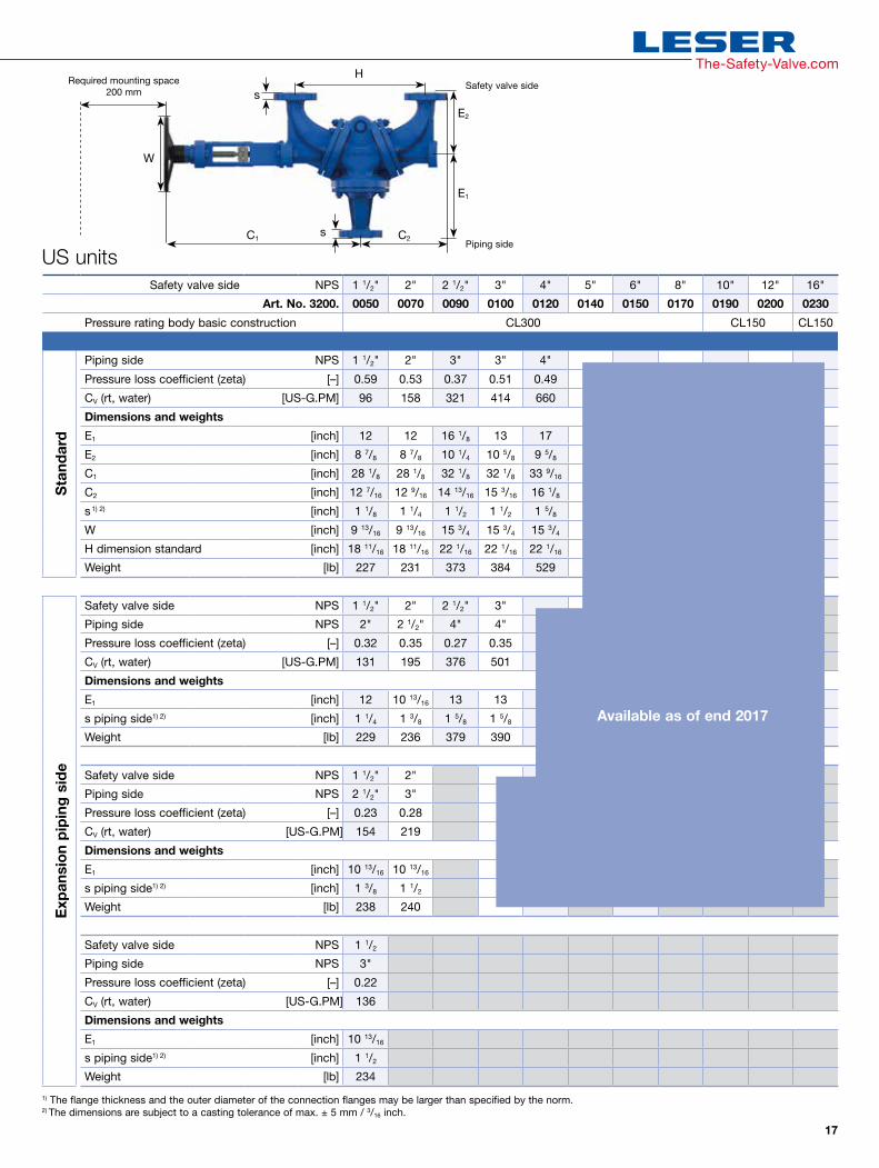
US units
H
W
Required mounting space 200 mm
E2
E1
s
C1 C2s
Safety valve side
Piping side
Safety valve side NPS 1 1/2" 2" 2 1/2" 3" 4" 5" 6" 8" 10" 12" 16"
Art. No. 3200. 0050 0070 0090 0100 0120 0140 0150 0170 0190 0200 0230
Pressure rating body basic construction CL300 CL150 CL150
Sta
ndar
d
Piping side NPS 1 1/2" 2" 3" 3" 4"
Pressure loss coefficient (zeta) [–] 0.59 0.53 0.37 0.51 0.49
CV (rt, water) [US-G.PM] 96 158 321 414 660
Dimensions and weights
E1 [inch] 12 12 16 1/8 13 17
E2 [inch] 8 7/8 8 7/8 10 1/4 10 5/8 9 5/8
C1 [inch] 28 1/8 28 1/8 32 1/8 32 1/8 33 9/16
C2 [inch] 12 7/16 12 9/16 14 13/ 16 15 3/16 16 1/8
s1) 2) [inch] 1 1/8 1 1/4 1 1/2 1 1/2 1 5/8
W [inch] 9 13/16 9 13/16 15 3/4 15 3/4 15 3/4
H dimension standard [inch] 18 11/16 18 11/16 22 1/16 22 1/16 22 1/16
Weight [lb] 227 231 373 384 529
Exp
ansi
on
pip
ing
sid
e
Safety valve side NPS 1 1/2" 2" 2 1/2" 3"
Piping side NPS 2" 2 1/2" 4" 4"
Pressure loss coefficient (zeta) [–] 0.32 0.35 0.27 0.35
CV (rt, water) [US-G.PM] 131 195 376 501
Dimensions and weights
E1 [inch] 12 10 13/16 13 13
s piping side1) 2) [inch] 1 1/4 1 3/8 1 5/8 1 5/8
Weight [lb] 229 236 379 390
Safety valve side NPS 1 1/2" 2"
Piping side NPS 2 1/2" 3"
Pressure loss coefficient (zeta) [–] 0.23 0.28
CV (rt, water) [US-G.PM] 154 219
Dimensions and weights
E1 [inch] 10 13/16 10 13/16
s piping side1) 2) [inch] 1 3/8 1 1/2
Weight [lb] 238 240
Safety valve side NPS 1 1/2
Piping side NPS 3"
Pressure loss coefficient (zeta) [–] 0.22
CV (rt, water) [US-G.PM] 136
Dimensions and weights
E1 [inch] 10 13/16
s piping side1) 2) [inch] 1 1/2
Weight [lb] 234
1) The flange thickness and the outer diameter of the connection flanges may be larger than specified by the norm.2) The dimensions are subject to a casting tolerance of max. ± 5 mm / 3/16 inch.
Available as of end 2017
18
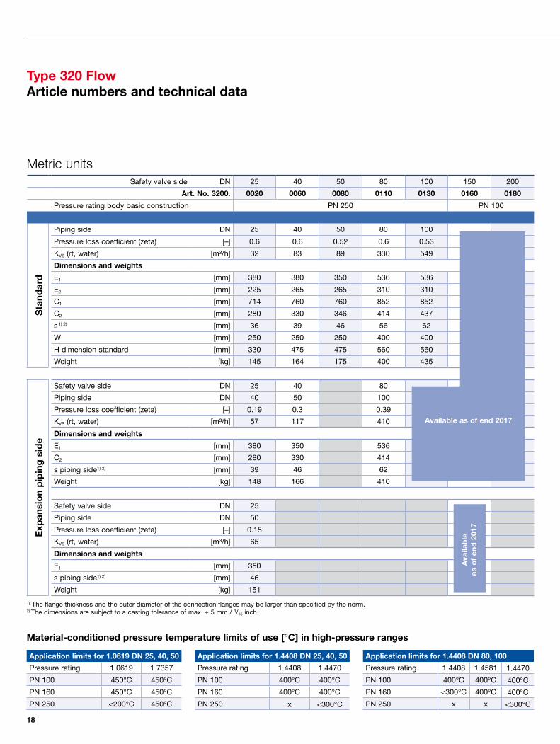
Type 320 FlowArticle numbers and technical data
Application limits for 1.0619 DN 25, 40, 50
Pressure rating 1.0619 1.7357
PN 100 450°C 450°C
PN 160 450°C 450°C
PN 250 <200°C 450°C
Application limits for 1.4408 DN 25, 40, 50
Pressure rating 1.4408 1.4470
PN 100 400°C 400°C
PN 160 400°C 400°C
PN 250 x <300°C
Application limits for 1.4408 DN 80, 100
Pressure rating 1.4408 1.4581 1.4470
PN 100 400°C 400°C 400°C
PN 160 <300°C 400°C 400°C
PN 250 x x <300°C
Material-conditioned pressure temperature limits of use [°C] in high-pressure ranges
Safety valve side DN 25 40 50 80 100 150 200
Art. No. 3200. 0020 0060 0080 0110 0130 0160 0180
Pressure rating body basic construction PN 250 PN 100
Sta
ndar
d
Piping side DN 25 40 50 80 100
Pressure loss coefficient (zeta) [–] 0.6 0.6 0.52 0.6 0.53
KVS (rt, water) [m³/h] 32 83 89 330 549
Dimensions and weights
E1 [mm] 380 380 350 536 536
E2 [mm] 225 265 265 310 310
C1 [mm] 714 760 760 852 852
C2 [mm] 280 330 346 414 437
s1) 2) [mm] 36 39 46 56 62
W [mm] 250 250 250 400 400
H dimension standard [mm] 330 475 475 560 560
Weight [kg] 145 164 175 400 435
Exp
ansi
on
pip
ing
sid
e
Safety valve side DN 25 40 80
Piping side DN 40 50 100
Pressure loss coefficient (zeta) [–] 0.19 0.3 0.39
KVS (rt, water) [m³/h] 57 117 410
Dimensions and weights
E1 [mm] 380 350 536
C2 [mm] 280 330 414
s piping side1) 2) [mm] 39 46 62
Weight [kg] 148 166 410
Safety valve side DN 25
Piping side DN 50
Pressure loss coefficient (zeta) [–] 0.15
KVS (rt, water) [m³/h] 65
Dimensions and weights
E1 [mm] 350
s piping side1) 2) [mm] 46
Weight [kg] 151
Available as of end 2017
1) The flange thickness and the outer diameter of the connection flanges may be larger than specified by the norm.2) The dimensions are subject to a casting tolerance of max. ± 5 mm / 3/16 inch.
Ava
ilab
le
as o
f en
d 2
017
Metric units

19
The-Safety-Valve.comThe-Safety-Valve.com
Application limits for WCB 1", 1 1/2", 2"
Pressure rating WCB WC6
CL600 842 °F 842 °F
CL900 842 °F 842 °F
CL1500 < 392°F 842 °F
Application limits for CF8M 1", 1 1/2", 2"
Pressure rating CF8M CD3MN
CL600 752°F 752°F
CL900 752°F 752°F
CL1500 x < 572°F
Application limits for CF8M 3", 4"
Pressure rating CF8M CF10M CD3MN
CL600 752°F 752°F 752°F
CL900 < 572°F 752°F 752°F
CL1500 x x < 572°F
Material-conditioned pressure temperature limits of use [°F] in high-pressure ranges
Safety valve side NPS 1" 1 1/2'' 2'' 3" 4" 6" 8"
Art. No. 3200. 0020 0060 0080 0110 0130 0160 0180
Pressure rating body basic construction CL1500 CL600
Sta
ndar
d
Piping side NPS 1" 1 1/2" 2" 3" 4"
Pressure loss coefficient (zeta) [–] 0.6 0.6 0.52 0.6 0.53
CV (rt, water) [US-G.PM] 37 95 103 382 635
Dimensions and weights
E1 [inch] 14 15/16 14 15/16 13 3/4 21 1/8 21 1/8
E2 [inch] 8 7/8 10 7/16 10 7/16 12 3/16 12 3/16
C1 [inch] 28 1/8 29 15/16 29 15/16 33 9/16 33 9/16
C2 [inch] 11 13 13 5/8 16 5/16 17 3/16
s1) 2) [inch] 1 7/16 1 9/16 1 13/16 2 3/16 2 7/16
W [inch] 9 13/16 9 13/16 9 13/16 15 3/4 15 3/4
H dimension standard [inch] 13 18 11/16 18 11/16 22 1/16 22 1/16
Weight [lb] 320 362 386 882 959
Exp
ansi
on
pip
ing
sid
e
Safety valve side NPS 1" 1 1/2" 3"
Piping side NPS 1 1/2" 2" 4"
Pressure loss coefficient (zeta) [–] 0.19 0.3 0.39
CV (rt, water) [US-G.PM] 66 135 474
Dimensions and weights
E1 [inch] 14 15/16 13 3/4 21 1/8
C2 [inch] 11 13 16 5/16
s piping side1) 2) [inch] 1 9/16 1 13/16 2 7/16
Weight [lb] 326 366 904
Safety valve side NPS 1"
Piping side NPS 2"
Pressure loss coefficient (zeta) [–] 0.15
CV (rt, water) [US-G.PM] 75
Dimensions and weights
E1 [inch] 13 3/4
s piping side1) 2) [inch] 1 13/16
Weight [lb] 333
Available as of end 2017
1) The flange thickness and the outer diameter of the connection flanges may be larger than specified by the norm.2) The dimensions are subject to a casting tolerance of max. ± 5 mm / 3/16 inch.
US units
Ava
ilab
le
as o
f en
d 2
017
H
W
Required mounting space 200 mm
E2
E1
s
C1 C2s
Safety valve side
Piping side
20
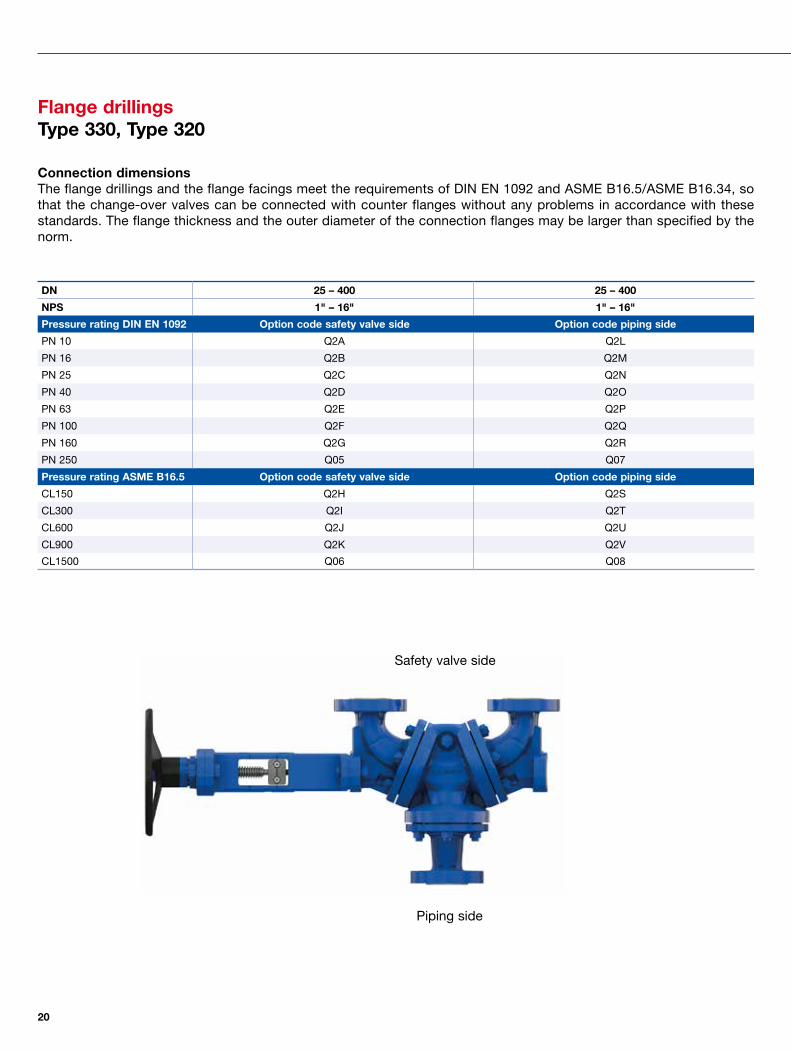
Flange drillingsType 330, Type 320
Connection dimensionsThe flange drillings and the flange facings meet the requirements of DIN EN 1092 and ASME B16.5/ASME B16.34, so that the change-over valves can be connected with counter flanges without any problems in accordance with these standards. The flange thickness and the outer diameter of the connection flanges may be larger than specified by the norm.
DN 25 – 400 25 – 400
NPS 1" – 16" 1" – 16"
Pressure rating DIN EN 1092 Option code safety valve side Option code piping side
PN 10 Q2A Q2L
PN 16 Q2B Q2M
PN 25 Q2C Q2N
PN 40 Q2D Q2O
PN 63 Q2E Q2P
PN 100 Q2F Q2Q
PN 160 Q2G Q2R
PN 250 Q05 Q07
Pressure rating ASME B16.5 Option code safety valve side Option code piping side
CL150 Q2H Q2S
CL300 Q2I Q2T
CL600 Q2J Q2U
CL900 Q2K Q2V
CL1500 Q06 Q08
Piping side
Safety valve side
21
The-Safety-Valve.com
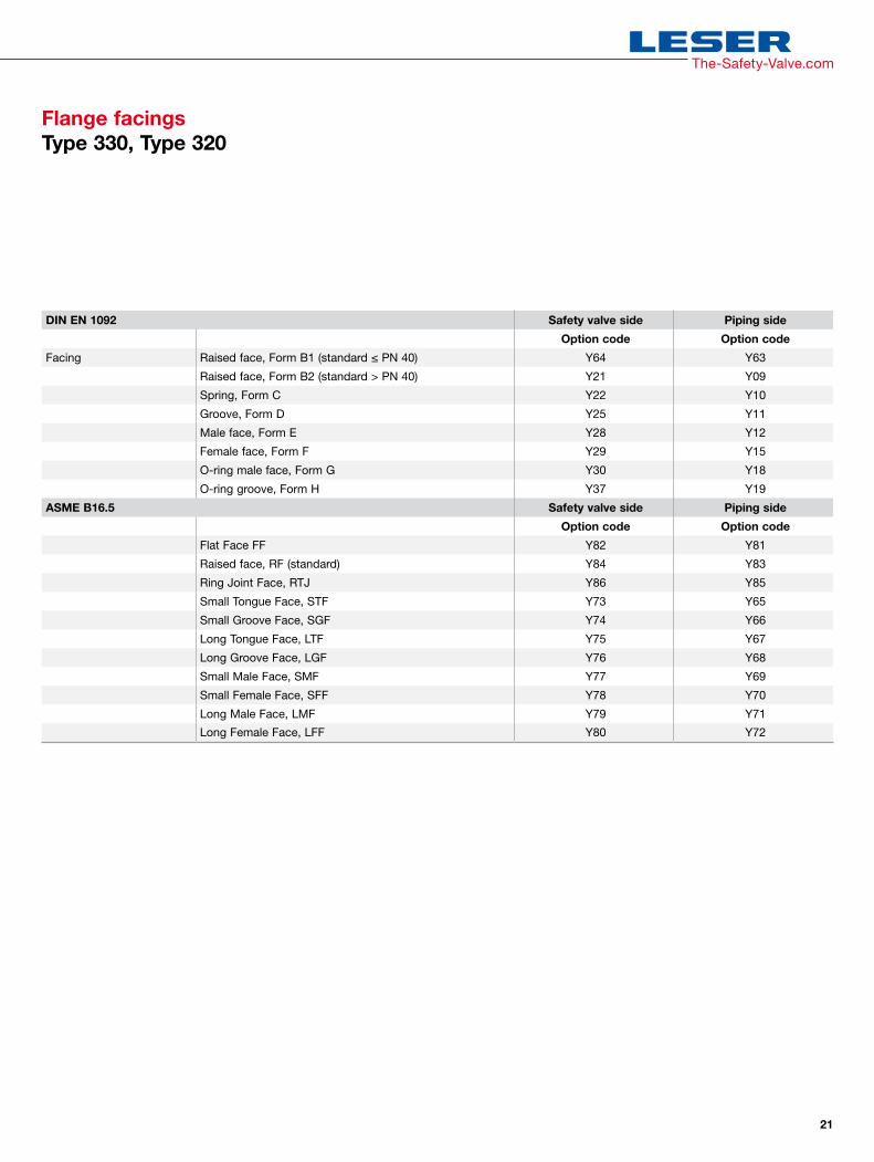
Flange facingsType 330, Type 320
DIN EN 1092 Safety valve side Piping side
Option code Option code
Facing Raised face, Form B1 (standard ≤ PN 40) Y64 Y63
Raised face, Form B2 (standard > PN 40) Y21 Y09
Spring, Form C Y22 Y10
Groove, Form D Y25 Y11
Male face, Form E Y28 Y12
Female face, Form F Y29 Y15
O-ring male face, Form G Y30 Y18
O-ring groove, Form H Y37 Y19
ASME B16.5 Safety valve side Piping side
Option code Option code
Flat Face FF Y82 Y81
Raised face, RF (standard) Y84 Y83
Ring Joint Face, RTJ Y86 Y85
Small Tongue Face, STF Y73 Y65
Small Groove Face, SGF Y74 Y66
Long Tongue Face, LTF Y75 Y67
Long Groove Face, LGF Y76 Y68
Small Male Face, SMF Y77 Y69
Small Female Face, SFF Y78 Y70
Long Male Face, LMF Y79 Y71
Long Female Face, LFF Y80 Y72

22
Lockable combinationType 330, Type 320
Lockable combinationA lockable combination is present if a change-over valve has been installed at the inlet as well as at the outlet of the safety valves. The inlet-side combination is expanded by the outlet-side change-over valve and the change-over valves are connected or locked so that improper operation is impossible.
Combinatorics and variable flange distanceLESER Change-over Valves are available in the same pressure ratings and nominal sizes as safety valve inlet and outlet in lockable combinations. This is made possible by the variable flange distance of the inlet-side change-over valve and a compansation of the adjustment range using different chain wheel transmissions.
ApplicationsThe lockable combination is used if the combined safety valves are not discharge into the atmosphere. This situation is the case with valuable media or media dangerous to persons and the environment. The safety valves are connected to a joint blow-off line through the lockable combination, while a safety valve is isolated and the other active safety valve secures the system. Due to the combination of two change-over valves with two safety valves, the entire unit only requires one piping at inlet and outlet.
The two change-over valves are supplemented through combination components for the combination and connected via a chain so as to ensure synchronised opening and closing.
Item Component Material
419 Tolerance compensation1.0619
WCB/WCC
420 Chain wheel1.0503
C45
431, 432 Chain with chain lockSteel
Steel
431
432
420
Inlet-side combination Lockable combination
419

23
The-Safety-Valve.com
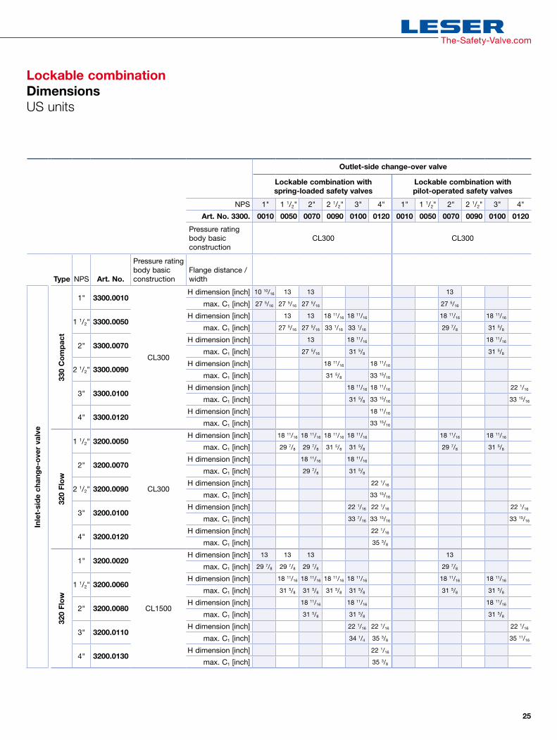
Lockable combinationType 330, Type 320
DimensionsThe dimensions of the lockable combination result from the selected safety valves and the change-over valves. The total height G is the sum of dimensions E1 + E2 of the change-over valve and the total height of the safety valves Hmax. The total width of the lockable combination is larger than the inlet-side combination due to the combination components.
Deviating C1 dimension in lockable combinations
C2
E1
E2
Hmax
C1
G

24
Outlet-side change-over valve
Lockable combination with spring-loaded safety valves
Lockable combination with pilot-operated safety valves
DN 25 40 50 65 80 100 25 40 50 65 80 100
Art. No. 3300. 0010 0050 0070 0090 0100 0120 0010 0050 0070 0090 0100 0120
Pressure rating body basic construction
PN 40 PN 40
Type DN Art. No.
Pressure rating body basic construction
Flange distance /width
Inle
t-si
de
chan
ge-
ove
r va
lve
330
Co
mp
act
25 3300.0010
PN 40
H dimension [mm] 270 330 330 330
max. C1 [mm] 694 694 694 694
40 3300.0050H dimension [mm] 330 330 475 475 475 475
max. C1 [mm] 694 694 840 840 759 804
50 3300.0070H dimension [mm] 330 475 475
max. C1 [mm] 694 804 804
65 3300.0090H dimension [mm] 475 475
max. C1 [mm] 804 861,5
80 3300.0100H dimension [mm] 475 475 560
max. C1 [mm] 804 861,5 861,5
100 3300.0120H dimension [mm] 475
max. C1 [mm] 861,5
320
Flo
w
40 3200.0050
PN 40
H dimension [mm] 475 475 475 475 475 475
max. C1 [mm] 759 759 804 804 759 804
50 3200.0070H dimension [mm] 475 475 475
max. C1 [mm] 759 804 804
65 3200.0090H dimension [mm] 560
max. C1 [mm] 861,5
80 3200.0100H dimension [mm] 560 560 560
max. C1 [mm] 849 861,5 861,5
100 3200.0120H dimension [mm] 560
max. C1 [mm] 900
320
Flo
w
25 3200.0020
PN 250
H dimension [mm] 330 330 330 330
max. C1 [mm] 759 759 759 759
40 3200.0060H dimension [mm] 475 475 475 475 475 475
max. C1 [mm] 804 804 804 804 804 804
50 3200.0080H dimension [mm] 475 475 475
max. C1 [mm] 804 804 804
80 3200.0110H dimension [mm] 560 560 560
max. C1 [mm] 869 900 906,5
100 3200.0130H dimension [mm] 560
max. C1 [mm] 900
Lockable combinationDimensionsMetric units
25
Outlet-side change-over valve
Lockable combination with spring-loaded safety valves
Lockable combination with pilot-operated safety valves
NPS 1" 1 1/2" 2" 2 1/2" 3" 4" 1" 1 1/2" 2" 2 1/2" 3" 4"
Art. No. 3300. 0010 0050 0070 0090 0100 0120 0010 0050 0070 0090 0100 0120
Pressure rating body basic construction
CL300 CL300
Type NPS Art. No.
Pressure rating body basic construction
Flange distance /width
Inle
t-si
de
chan
ge-
ove
r va
lve
330
Co
mp
act
1" 3300.0010
CL300
H dimension [inch] 10 10/16 13 13 13
max. C1 [inch] 27 5/16 27 5/16 27 5/16 27 5/16
1 1/2" 3300.0050H dimension [inch] 13 13 18 11/16 18 11/16 18 11/16 18 11/16
max. C1 [inch] 27 5/16 27 5/16 33 1/16 33 1/16 29 7/8 31 5/8
2" 3300.0070H dimension [inch] 13 18 11/16 18 11/16
max. C1 [inch] 27 5/16 31 5/8 31 5/8
2 1/2" 3300.0090H dimension [inch] 18 11/16 18 11/16
max. C1 [inch] 31 5/8 33 15/16
3" 3300.0100H dimension [inch] 18 11/16 18 11/16 22 1/16
max. C1 [inch] 31 5/8 33 15/16 33 15/16
4" 3300.0120H dimension [inch] 18 11/16
max. C1 [inch] 33 15/16
320
Flo
w
1 1/2" 3200.0050
CL300
H dimension [inch] 18 11/16 18 11/16 18 11/16 18 11/16 18 11/16 18 11/16
max. C1 [inch] 29 7/8 29 7/8 31 5/8 31 5/8 29 7/8 31 5/8
2" 3200.0070H dimension [inch] 18 11/16 18 11/16
max. C1 [inch] 29 7/8 31 5/8
2 1/2" 3200.0090H dimension [inch] 22 1/16
max. C1 [inch] 33 15/16
3" 3200.0100H dimension [inch] 22 1/16 22 1/16 22 1/16
max. C1 [inch] 33 7/16 33 15/16 33 15/16
4" 3200.0120H dimension [inch] 22 1/16
max. C1 [inch] 35 3/8
320
Flo
w
1" 3200.0020
CL1500
H dimension [inch] 13 13 13 13
max. C1 [inch] 29 7/8 29 7/8 29 7/8 29 7/8
1 1/2" 3200.0060H dimension [inch] 18 11/16 18 11/16 18 11/16 18 11/16 18 11/16 18 11/16
max. C1 [inch] 31 5/8 31 5/8 31 5/8 31 5/8 31 5/8 31 5/8
2" 3200.0080H dimension [inch] 18 11/16 18 11/16 18 11/16
max. C1 [inch] 31 5/8 31 5/8 31 5/8
3" 3200.0110H dimension [inch] 22 1/16 22 1/16 22 1/16
max. C1 [inch] 34 1/4 35 3/8 35 11/16
4" 3200.0130H dimension [inch] 22 1/16
max. C1 [inch] 35 3/8
The-Safety-Valve.com
Lockable combinationDimensionsUS units
26
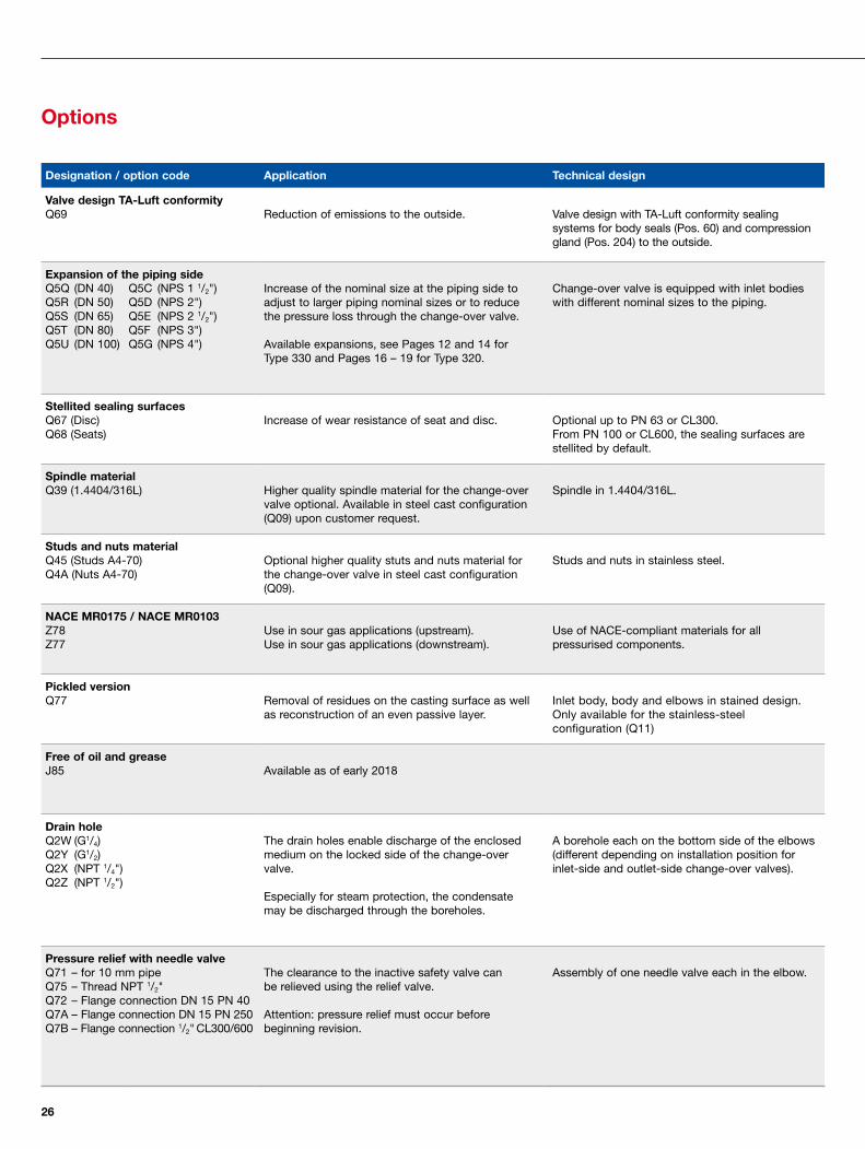
Options
Designation / option code Application Technical design
Valve design TA-Luft conformityQ69 Reduction of emissions to the outside. Valve design with TA-Luft conformity sealing
systems for body seals (Pos. 60) and compression gland (Pos. 204) to the outside.
Expansion of the piping sideIncrease of the nominal size at the piping side to adjust to larger piping nominal sizes or to reduce the pressure loss through the change-over valve.
Available expansions, see Pages 12 and 14 for Type 330 and Pages 16 – 19 for Type 320.
Change-over valve is equipped with inlet bodies with different nominal sizes to the piping.
Q5Q (DN 40)Q5R (DN 50)Q5S (DN 65)Q5T (DN 80)Q5U (DN 100)
Q5C (NPS 1 1/2")Q5D (NPS 2")Q5E (NPS 2 1/2")Q5F (NPS 3")Q5G (NPS 4")
Stellited sealing surfacesQ67 (Disc)Q68 (Seats)
Increase of wear resistance of seat and disc. Optional up to PN 63 or CL300.From PN 100 or CL600, the sealing surfaces are stellited by default.
Spindle materialQ39 (1.4404/316L) Higher quality spindle material for the change-over
valve optional. Available in steel cast configuration (Q09) upon customer request.
Spindle in 1.4404/316L.
Studs and nuts materialQ45 (Studs A4-70)Q4A (Nuts A4-70)
Optional higher quality stuts and nuts material for the change-over valve in steel cast configuration (Q09).
Studs and nuts in stainless steel.
NACE MR0175 / NACE MR0103Z78Z77
Use in sour gas applications (upstream).Use in sour gas applications (downstream).
Use of NACE-compliant materials for all pressurised components.
Pickled versionQ77 Removal of residues on the casting surface as well
as reconstruction of an even passive layer.Inlet body, body and elbows in stained design. Only available for the stainless-steel configuration (Q11)
Free of oil and greaseJ85 Available as of early 2018
Drain holeQ2W (G1/4)Q2Y (G1/2)Q2X (NPT 1/4")Q2Z (NPT 1/2")
The drain holes enable discharge of the enclosed medium on the locked side of the change-over valve.
Especially for steam protection, the condensate may be discharged through the boreholes.
A borehole each on the bottom side of the elbows (different depending on installation position for inlet-side and outlet-side change-over valves).
Pressure relief with needle valveQ71 – for 10 mm pipeQ75 – Thread NPT 1/2" Q72 – Flange connection DN 15 PN 40Q7A – Flange connection DN 15 PN 250Q7B – Flange connection 1/2" CL300/600
The clearance to the inactive safety valve can be relieved using the relief valve.
Attention: pressure relief must occur before beginning revision.
Assembly of one needle valve each in the elbow.
27
The-Safety-Valve.com
Designation / option code Application Technical design
Remote sensingQ73 (in the inlet body for POSV) Remote sensing connection for POSV in order
to reduce the pressure directly in the inlet of the change-over valve and thereby bridge the pressure loss via the change-over valve.
Connection borehole on the back side of the inlet body inclusiv piping between inlet body and the two elbows.
In addition, a switch valve is supplied for remote sensing line to switch between both sides in order to prevent medium from discharging.
Purge and manometer connectionQ3A (NPT 1/2")Q3B (G1/2)
The purge and manometer connection is used for cleaning and/or purging the locked elbow. As an alternative, the connection for pressure monitoring in the locked elbow may be used by connecting a manometer.
It can then display pressure increase due to leaks or the general locked pressure in order to demount the safety valve on the locked side without danger.
One connection each on the front side of the elbows locked with a plastic plug.
Proximity switchQ76 Adaptor M12x1)J93 (N M12x1/M18X1 direct current)
The proximity switches provide an electronic signal indicating on which side (left or right) the disc of the change-over valve is located and therefore which safety valve is active and which one is set to stand-by.
Two proximity switches are screwed into the two end positions in the yoke above the position indicator.
Adjustment guard manual wheelQ3C Protection against unauthorised switching Padlock in the boreholes of the yoke.
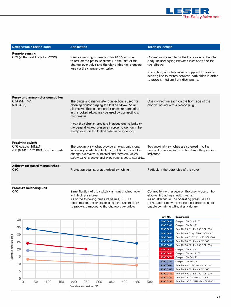
Pressure balancing unitQ70 Simplification of the switch via manual wheel even
with high pressures.As of the following pressure values, LESER recommends the pressure balancing unit in order to prevent damages to the change-over valve:
Connection with a pipe on the back sides of the elbows, including a switch valve.As an alternative, the operating pressure can be reduced below the mentioned limits so as to enable switching without any danger.
Ope
ratin
g pr
essu
re
[bar
]
Operating temperature [°C]
Art. No. Designation
3300.0090 Compact DN 65 / 2 1/2"
3300.0100 Compact DN 80 / 3"
3200.0020 Flow DN 25 / 1" PN 250 / CL1500
3200.0050 Flow DN 40 /1 1/2" PN 40 / CL300
3200.0060 Flow DN 40 / 1 1/2" PN 250 / CL1500
3200.0070 Flow DN 50 / 2" PN 40 / CL300
3200.0080 Flow DN 50 / 2" PN 250 / CL1500
3300.0010 Compact DN 25 / 1"
3300.0050 Compact DN 40 / 1 1/2"
3300.0070 Compact DN 50 / 2"
3300.0120 Compact DN 100 / 4"
3200.0090 Flow DN 65 / 2 1/2" PN 40 / CL300
3200.0100 Flow DN 80 / 3" PN 40 / CL300
3200.0110 Flow DN 80 / 3" PN 250 / CL1500
3200.0120 Flow DN 100 / 4" PN 40 / CL300
3200.0130 Flow DN 100 / 4" PN 250 / CL1500
40
35
30
25
20
15
10
5
00 50 100 150 200 250 300 350 400 500450
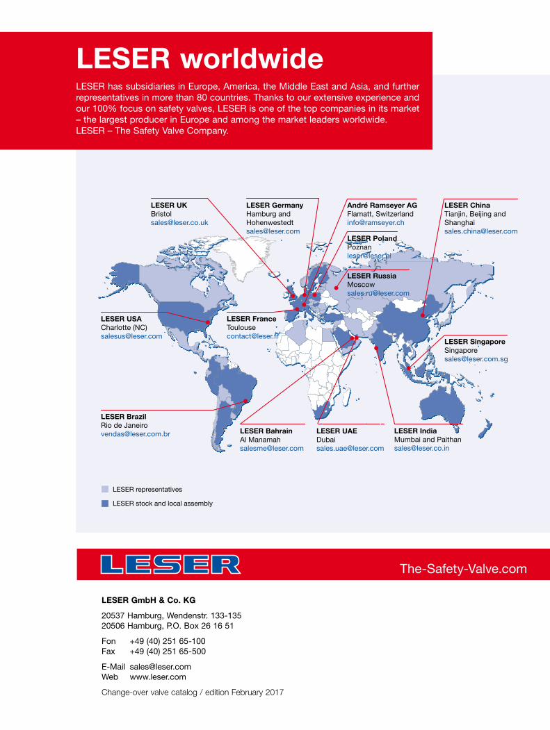
LESER worldwideLESER has subsidiaries in Europe, America, the Middle East and Asia, and further representatives in more than 80 countries. Thanks to our extensive experience and our 100% focus on safety valves, LESER is one of the top companies in its market – the largest producer in Europe and among the market leaders worldwide. LESER – The Safety Valve Company.
The-Safety-Valve.com
LESER GmbH & Co. KG
20537 Hamburg, Wendenstr. 133-135 20506 Hamburg, P.O. Box 26 16 51
Fon +49 (40) 251 65-100 Fax +49 (40) 251 65-500
E-Mail [email protected] Web www.leser.com
Change-over valve catalog / edition February 2017
LESER representatives
LESER stock and local assembly
LESER USACharlotte (NC) [email protected]
LESER [email protected]
LESER GermanyHamburg and [email protected]
LESER [email protected]
André Ramseyer AGFlamatt, [email protected]
LESER [email protected]
LESER [email protected]
LESER Singapore [email protected]
LESER IndiaMumbai and [email protected]
LESER Bahrain Al [email protected]
LESER UAE [email protected]
LESER Brazil Rio de [email protected]
LESER ChinaTianjin, Beijing and [email protected]