Embed Size (px)
Citation preview

Bentley OpenRoads Workshop
2017 FLUG Fall Training Event
F-1E - QuickStart using OpenRoads ConceptStation
Bentley Systems, Incorporated 685 Stockton Drive Exton, PA 19341 www.bentley.com
Practice WorkbookThis workbook is designed for use in Live instructor-led training and for OnDemand self study. OnDemand videos for this course are available through CONNECT Advisor and on the LEARN Server.
DO NOT DISTRIBUTE - Printing for student use is permitted
TRNC02403-1/0007
QuickStart Using OpenRoads ConceptStationCONNECT Edition(10.00.05.99)About this Practice Workbook...
This PDF file includes bookmarks providing an overview of the document. Click on the bookmark to quickly jump to any section in the file.
Both Imperial and Metric files are included in the dataset. Throughout this practice workbook Imperial values are specified first and the metric values second with the metric values enclosed in square brackets. For example: 12’ [3.4m]
Have a Question? Need Help?
If you have questions while taking this course, submit them to the Civil Design Forum on Bentley Communities where peers and Bentley subject matter experts are available to help.
Copyright © 2017 Bentley Systems, Incorporated 2DO NOT DISTRIBUTE - Printing for student use is permitted
Exercise 1: Create Roads
DescriptionIn this exercise you will learn how to place a new road, select the road class, the template, and edit the geometry of the newly created road.
Skills Taught Navigate the software
Use the Place Road tool
Select Road Class and Template
Edit Curve Radii

Creating a New Project File
1. Start the OpenRoads ConceptStation application.
2. From the Open page, click New.
3. Type Intersection in the Name field.
4. Set the File Location to c:\Bentley Training\QuickStart Using OpenRoads ConceptStation or other location where the dataset was installed. This defines where the new file will be created.
5. Define the project area and Coordinate System.
This course uses a seed file that contains the appropriate definitions for this training project. The project area and coordinate system can also be defined manually as defined in the Appendix of this document.
a. Browse for the Seed File named IntersectionSeed.dgndb in the location where the dataset was installed.
The project extent as well as the Coordinate System is displayed.

Copyright © 2017 Bentley Systems, Incorporated 4DO NOT DISTRIBUTE - Printing for student use is permitted
b. Click Create.
The Context Data Import dialog appears.
c. Click Skip.
This dialog is used to import terrain, raster imagery, and other data into the project. The data can come from local files or from an online GeoCoordination service. This data does not have to be imported when the project is first created. It can be added to a project later by selecting Import or GeoCoordination Services from the Backstage.
Instead of importing data, the terrain and images for this project will be a scalable mesh attached as a reference.
Import from local files - Use to load terrain, raster imagery, and other data from files on your local computer or network. This is useful if you have already downloaded files from on an online GeoCoordination service or you have higher quality files from another source.
Use GeoCoordination Services - Use to download terrain, imagery, or roadway, building and hydrology data from online services.

Copyright © 2017 Bentley Systems, Incorporated 5DO NOT DISTRIBUTE - Printing for student use is permitted
Attaching a Terrain 3sm File
1. Select the Backstage.
2. Select Attach.
The Attach external data dialog appears.
3. Click on Computer to browse for the Terrain.3sm file in the location where the dataset was installed.
A 3sm file is a scalable mesh containing the imagery and the terrain.
4. Click Open.
The terrain model will display and you are now all set to start your design.
Copyright © 2017 Bentley Systems, Incorporated 6DO NOT DISTRIBUTE - Printing for student use is permitted
Understanding the Interface
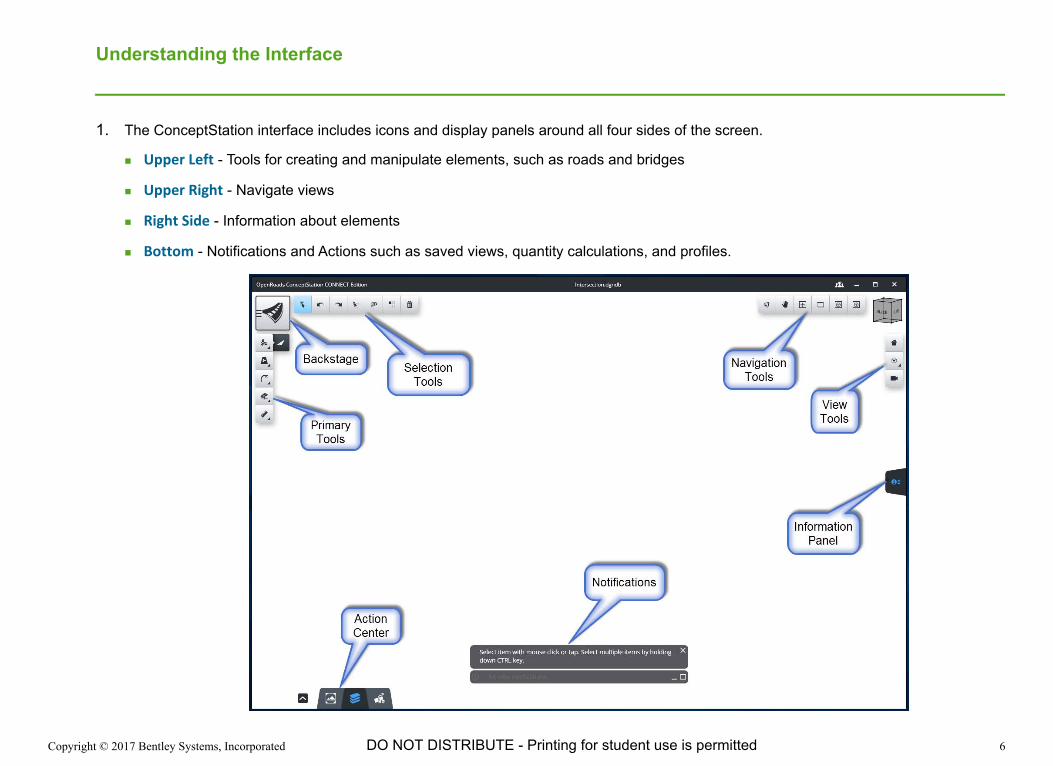
1. The ConceptStation interface includes icons and display panels around all four sides of the screen.
Upper Left - Tools for creating and manipulate elements, such as roads and bridges
Upper Right - Navigate views
Right Side - Information about elements
Bottom - Notifications and Actions such as saved views, quantity calculations, and profiles.
Copyright © 2017 Bentley Systems, Incorporated 7DO NOT DISTRIBUTE - Printing for student use is permitted
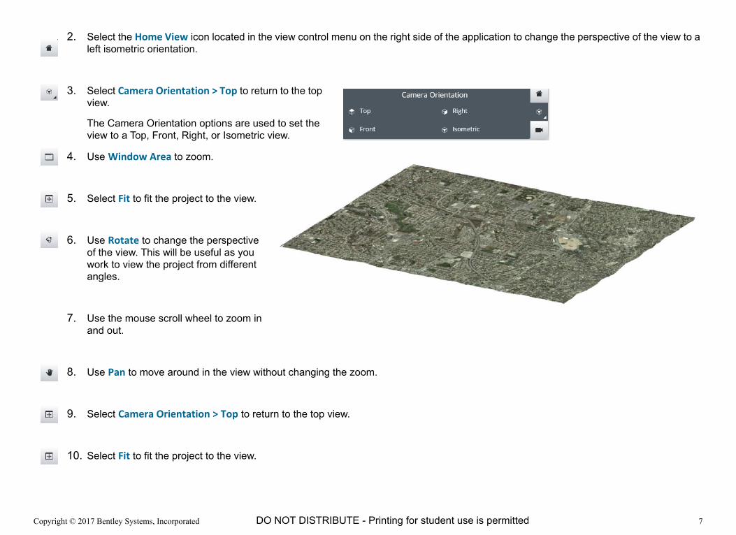
2. Select the Home View icon located in the view control menu on the right side of the application to change the perspective of the view to a left isometric orientation.
3. Select Camera Orientation > Top to return to the top view.
The Camera Orientation options are used to set the view to a Top, Front, Right, or Isometric view.
4. Use Window Area to zoom.
5. Select Fit to fit the project to the view.
6. Use Rotate to change the perspective of the view. This will be useful as you work to view the project from different angles.
7. Use the mouse scroll wheel to zoom in and out.
8. Use Pan to move around in the view without changing the zoom.
9. Select Camera Orientation > Top to return to the top view.
10. Select Fit to fit the project to the view.

Copyright © 2017 Bentley Systems, Incorporated 8DO NOT DISTRIBUTE - Printing for student use is permitted
Setting Metric Display Units (Optional)
The display units can be changed to your desired measurement system.
1. If you wish to work in Imperial Units, skip this section and continue on the following page.
2. If you wish to work in Metric Units...
a. Select the Backstage.
b. Select Settings.
c. Change the Display Units to Meters.
3. To return to the modeling environment.
a. Select the Backstage.
b. Select Conceptualize.

Copyright © 2017 Bentley Systems, Incorporated 9DO NOT DISTRIBUTE - Printing for student use is permitted
Place a Divided Highway
1. Set the Camera Orientation to Top.
2. Zoom such that the area outlined in red in the image below is visible.
Copyright © 2017 Bentley Systems, Incorporated 10DO NOT DISTRIBUTE - Printing for student use is permitted
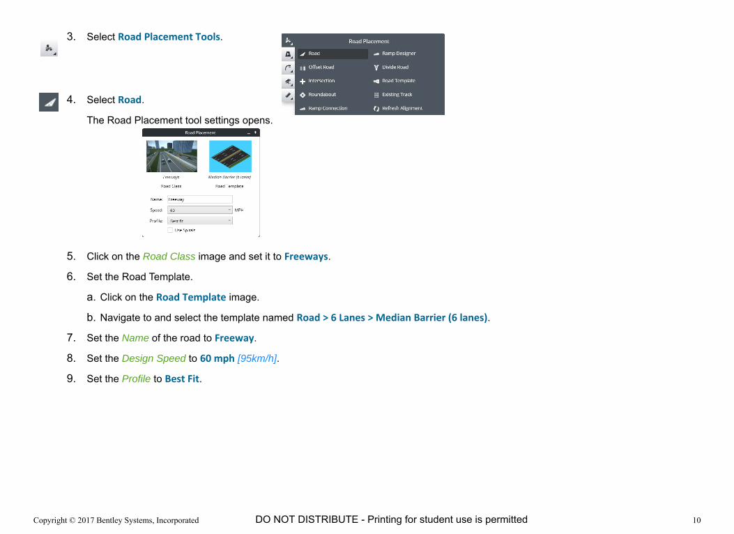
3. Select Road Placement Tools.
4. Select Road.
The Road Placement tool settings opens.
5. Click on the Road Class image and set it to Freeways.
6. Set the Road Template.
a. Click on the Road Template image.
b. Navigate to and select the template named Road > 6 Lanes > Median Barrier (6 lanes).
7. Set the Name of the road to Freeway.
8. Set the Design Speed to 60 mph [95km/h].
9. Set the Profile to Best Fit.

Copyright © 2017 Bentley Systems, Incorporated 11DO NOT DISTRIBUTE - Printing for student use is permitted
10. Place the road by clicking in the view to place four PIs approximately as shown in the following image.
11. When finished placing the fourth PI, Right Click to create and store the geometry.
12. Select the Element Selection tool or press the Esc key to exit the command.
TIP: The Esc key will exit any command and return to the Element Selection tool.
Copyright © 2017 Bentley Systems, Incorporated 12DO NOT DISTRIBUTE - Printing for student use is permitted
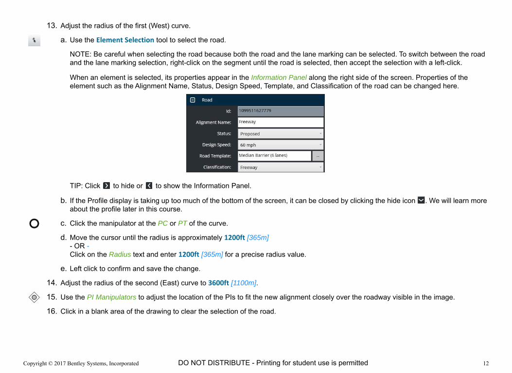
13. Adjust the radius of the first (West) curve.
a. Use the Element Selection tool to select the road.
NOTE: Be careful when selecting the road because both the road and the lane marking can be selected. To switch between the road and the lane marking selection, right-click on the segment until the road is selected, then accept the selection with a left-click.
When an element is selected, its properties appear in the Information Panel along the right side of the screen. Properties of the element such as the Alignment Name, Status, Design Speed, Template, and Classification of the road can be changed here.
TIP: Click to hide or to show the Information Panel.
b. If the Profile display is taking up too much of the bottom of the screen, it can be closed by clicking the hide icon . We will learn more about the profile later in this course.
c. Click the manipulator at the PC or PT of the curve.
d. Move the cursor until the radius is approximately 1200ft [365m] - OR -Click on the Radius text and enter 1200ft [365m] for a precise radius value.
e. Left click to confirm and save the change.
14. Adjust the radius of the second (East) curve to 3600ft [1100m].
15. Use the PI Manipulators to adjust the location of the PIs to fit the new alignment closely over the roadway visible in the image.
16. Click in a blank area of the drawing to clear the selection of the road.

Copyright © 2017 Bentley Systems, Incorporated 13DO NOT DISTRIBUTE - Printing for student use is permitted
Place an Arterial Street
1. Select the Road icon from the Road Placement Tools.
2. Set the Road Class to Urban Principal Arterial.
3. Set the Road Template to Curb (6 lanes).
4. Set the Name to Bell Road.
5. Set the Design Speed to 45 mph [70km/h].
6. Set the Profile to Best Fit.
7. Place the road by PI approximately as shown in the image.
8. When finished placing the last PI, Right Click to save the geometry.
9. Exit the command by clicking on the Element Selection tool.

Copyright © 2017 Bentley Systems, Incorporated 14DO NOT DISTRIBUTE - Printing for student use is permitted
Exercise 2: Create the Bridge
DescriptionIn this exercise you will learn how to create a bridge, edit the profile and edit the bridge piers.
Skills Taught Use the Place Bridge tool, select the bridge template and structure type
Edit the profile
Use the Measure Bridge Clearance tool
Edit the bridge
Copyright © 2017 Bentley Systems, Incorporated 15DO NOT DISTRIBUTE - Printing for student use is permitted
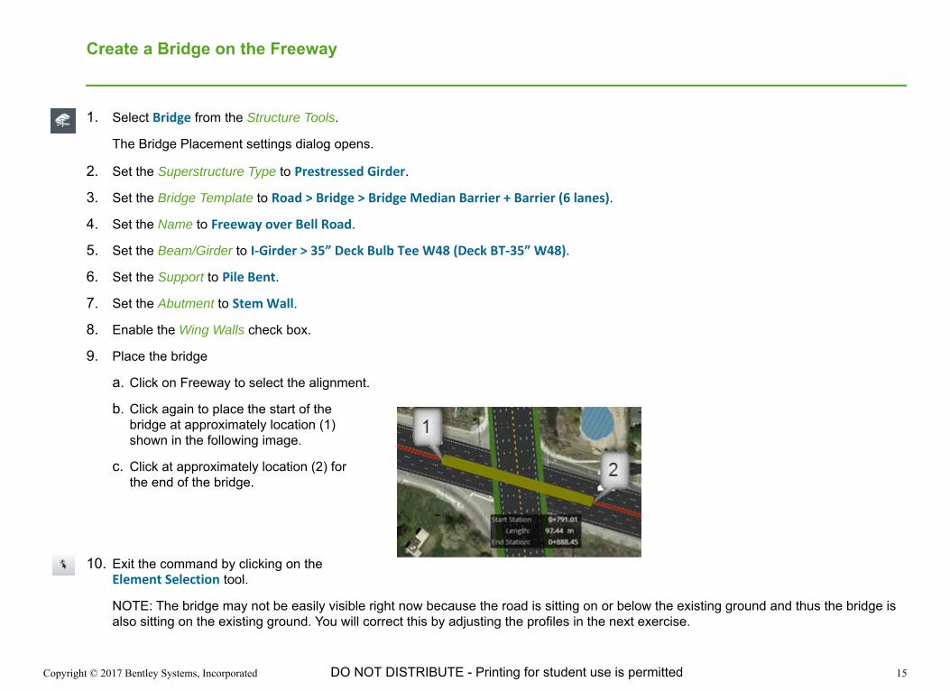
Create a Bridge on the Freeway
1. Select Bridge from the Structure Tools.
The Bridge Placement settings dialog opens.
2. Set the Superstructure Type to Prestressed Girder.
3. Set the Bridge Template to Road > Bridge > Bridge Median Barrier + Barrier (6 lanes).
4. Set the Name to Freeway over Bell Road.
5. Set the Beam/Girder to I-Girder > 35” Deck Bulb Tee W48 (Deck BT-35” W48).
6. Set the Support to Pile Bent.
7. Set the Abutment to Stem Wall.
8. Enable the Wing Walls check box.
9. Place the bridge
a. Click on Freeway to select the alignment.
b. Click again to place the start of the bridge at approximately location (1) shown in the following image.
c. Click at approximately location (2) for the end of the bridge.
10. Exit the command by clicking on the Element Selection tool.
NOTE: The bridge may not be easily visible right now because the road is sitting on or below the existing ground and thus the bridge is also sitting on the existing ground. You will correct this by adjusting the profiles in the next exercise.
Copyright © 2017 Bentley Systems, Incorporated 16DO NOT DISTRIBUTE - Printing for student use is permitted
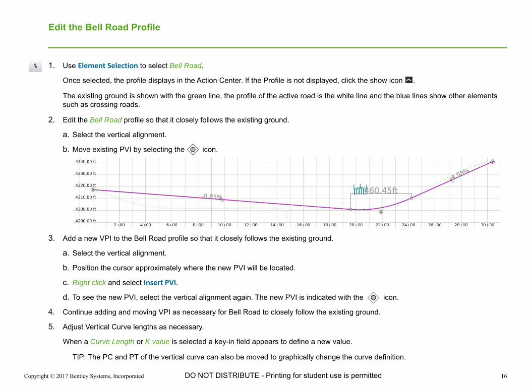
Edit the Bell Road Profile
1. Use Element Selection to select Bell Road.
Once selected, the profile displays in the Action Center. If the Profile is not displayed, click the show icon .
The existing ground is shown with the green line, the profile of the active road is the white line and the blue lines show other elements such as crossing roads.
2. Edit the Bell Road profile so that it closely follows the existing ground.
a. Select the vertical alignment.
b. Move existing PVI by selecting the icon.
3. Add a new VPI to the Bell Road profile so that it closely follows the existing ground.
a. Select the vertical alignment.
b. Position the cursor approximately where the new PVI will be located.
c. Right click and select Insert PVI.
d. To see the new PVI, select the vertical alignment again. The new PVI is indicated with the icon.
4. Continue adding and moving VPI as necessary for Bell Road to closely follow the existing ground.
5. Adjust Vertical Curve lengths as necessary.
When a Curve Length or K value is selected a key-in field appears to define a new value.
TIP: The PC and PT of the vertical curve can also be moved to graphically change the curve definition.
Copyright © 2017 Bentley Systems, Incorporated 17DO NOT DISTRIBUTE - Printing for student use is permitted
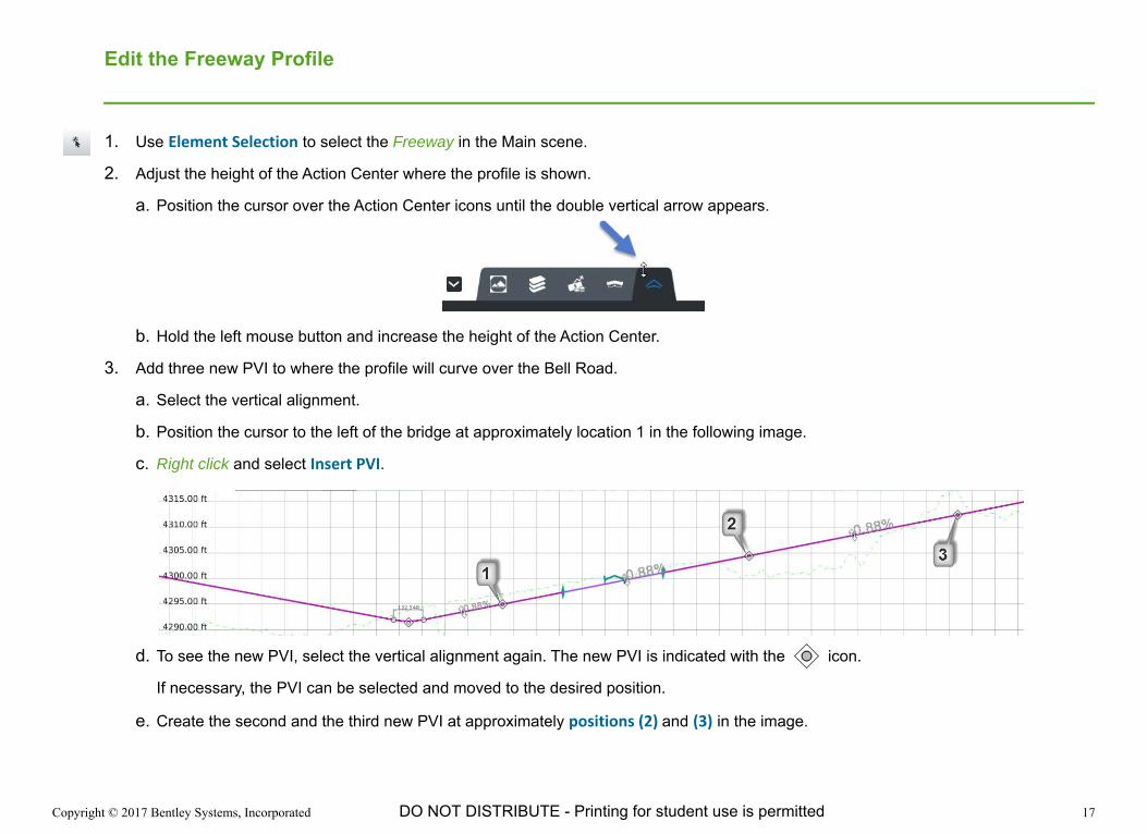
Edit the Freeway Profile
1. Use Element Selection to select the Freeway in the Main scene.
2. Adjust the height of the Action Center where the profile is shown.
a. Position the cursor over the Action Center icons until the double vertical arrow appears.
b. Hold the left mouse button and increase the height of the Action Center.
3. Add three new PVI to where the profile will curve over the Bell Road.
a. Select the vertical alignment.
b. Position the cursor to the left of the bridge at approximately location 1 in the following image.
c. Right click and select Insert PVI.
d. To see the new PVI, select the vertical alignment again. The new PVI is indicated with the icon.
If necessary, the PVI can be selected and moved to the desired position.
e. Create the second and the third new PVI at approximately positions (2) and (3) in the image.
Copyright © 2017 Bentley Systems, Incorporated 18DO NOT DISTRIBUTE - Printing for student use is permitted
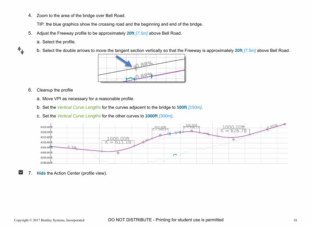
4. Zoom to the area of the bridge over Bell Road.
TIP: the blue graphics show the crossing road and the beginning and end of the bridge.
5. Adjust the Freeway profile to be approximately 20ft [7.5m] above Bell Road.
a. Select the profile.
b. Select the double arrows to move the tangent section vertically so that the Freeway is approximately 20ft [7.5m] above Bell Road.
6. Cleanup the profile
a. Move VPI as necessary for a reasonable profile.
b. Set the Vertical Curve Lengths for the curves adjacent to the bridge to 500ft [150m].
c. Set the Vertical Curve Lengths for the other curves to 1000ft [300m].
7. Hide the Action Center (profile view).
Copyright © 2017 Bentley Systems, Incorporated 19DO NOT DISTRIBUTE - Printing for student use is permitted
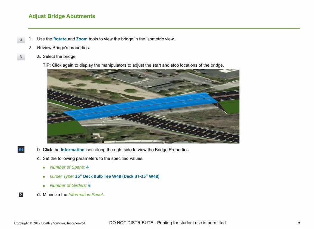
Adjust Bridge Abutments
1. Use the Rotate and Zoom tools to view the bridge in the isometric view.
2. Review Bridge's properties.
a. Select the bridge.
TIP: Click again to display the manipulators to adjust the start and stop locations of the bridge.
b. Click the Information icon along the right side to view the Bridge Properties.
c. Set the following parameters to the specified values.
Number of Spans: 4
Girder Type: 35” Deck Bulb Tee W48 (Deck BT-35” W48)
Number of Girders: 6
d. Minimize the Information Panel.

Copyright © 2017 Bentley Systems, Incorporated 20DO NOT DISTRIBUTE - Printing for student use is permitted
3. Set the Camera Orientation to Top.
4. Hide the bridge deck to make the piers easier to see and manipulate.
a. Select the bridge if it is not already selected.
b. Select Hide Selected Items from the Selection Tools.
The bridge deck (selected item) is hidden in the view.
5. Rotate and position the abutments to be parallel with Bell Road.
a. Select the west abutment.
Manipulator appears to rotate the abutment.
b. Use the rotate manipulator or the Skew parameter in the Information Panel to set the abutment skew approximately equal to Bell Road.
c. Edit the abutment properties on the Information Panel to set the following parameters to the specified values.
Left-side Wing Wall - Type: Cantilevered
Right-side Wing Wall - Type: Cantilevered
d. Select the approach adjacent to the abutments.
e. Click on the selected approach a second time and the location manipulators appear.
f. Using the location manipulators, adjust the length of the abutment to be long enough for the cantilevered abutment walls.
Copyright © 2017 Bentley Systems, Incorporated 21DO NOT DISTRIBUTE - Printing for student use is permitted
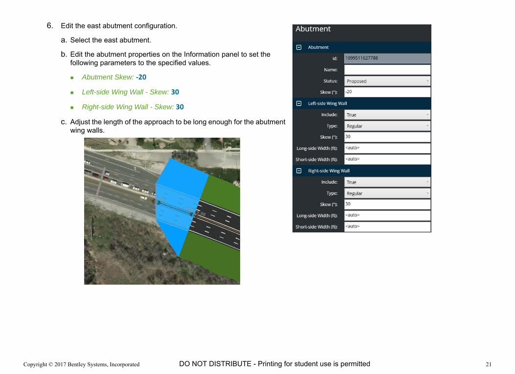
6. Edit the east abutment configuration.
a. Select the east abutment.
b. Edit the abutment properties on the Information panel to set the following parameters to the specified values.
Abutment Skew: -20
Left-side Wing Wall - Skew: 30
Right-side Wing Wall - Skew: 30
c. Adjust the length of the approach to be long enough for the abutment wing walls.

Copyright © 2017 Bentley Systems, Incorporated 22DO NOT DISTRIBUTE - Printing for student use is permitted
Adjust Bridge Piers
1. Set the Camera Orientation to Top.
2. Rotate the piers to be parallel with Bell Road.
a. Select the pier on the west side of Bell Road.
Manipulators appear to position and rotate the pier.
b. Rotate the pier to be approximately parallel with Bell Road by clicking on the circular arrow manipulator.
TIP: A precise skew angel can be entered in the Information Panel.
c. Move the pier to a desirable position using the arrow manipulators.
d. Repeat for the remaining piers to make sure no pier is in the middle of Bell Road. There should be two piers on the east side of Bell Road.
3. Unhide the Bridge Deck.
a. Select Item Display on the right side of the screen.
This information panel lists all elements that are currently hidden.
b. Select X for the Bridge item.
The bridge deck appears again in the Main stage.
Copyright © 2017 Bentley Systems, Incorporated 23DO NOT DISTRIBUTE - Printing for student use is permitted
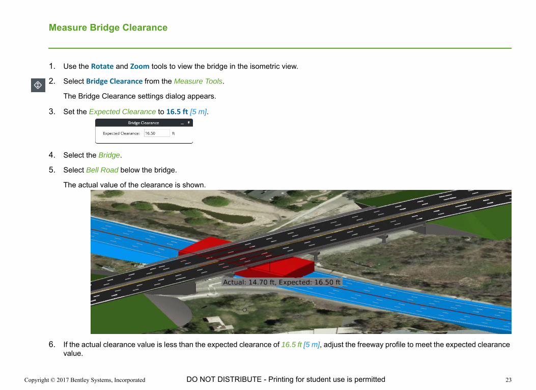
Measure Bridge Clearance
1. Use the Rotate and Zoom tools to view the bridge in the isometric view.
2. Select Bridge Clearance from the Measure Tools.
The Bridge Clearance settings dialog appears.
3. Set the Expected Clearance to 16.5 ft [5 m].
4. Select the Bridge.
5. Select Bell Road below the bridge.
The actual value of the clearance is shown.
6. If the actual clearance value is less than the expected clearance of 16.5 ft [5 m], adjust the freeway profile to meet the expected clearance value.
Copyright © 2017 Bentley Systems, Incorporated 24DO NOT DISTRIBUTE - Printing for student use is permitted
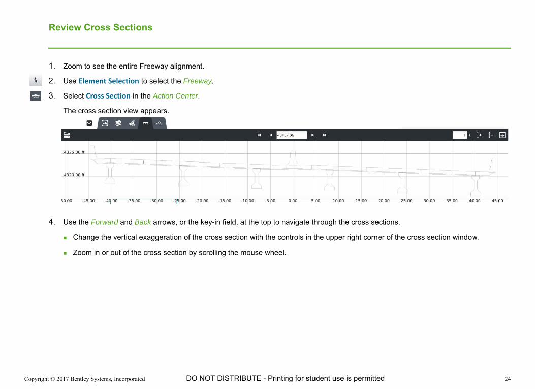
Review Cross Sections
1. Zoom to see the entire Freeway alignment.
2. Use Element Selection to select the Freeway.
3. Select Cross Section in the Action Center.
The cross section view appears.
4. Use the Forward and Back arrows, or the key-in field, at the top to navigate through the cross sections.
Change the vertical exaggeration of the cross section with the controls in the upper right corner of the cross section window.
Zoom in or out of the cross section by scrolling the mouse wheel.

Copyright © 2017 Bentley Systems, Incorporated 25DO NOT DISTRIBUTE - Printing for student use is permitted
Exercise 3: Create Ramps
DescriptionIn this exercise you will learn how to create a ramp using the ramp designer tool. The Ramp Designer tool is used to create ramp geometry, connectors, and intersections in a single process. This tool can be used to create loop or diagonal ramps each with a intersection or directional connector to the secondary road.
Skills Taught Ramp Designer Tool

Copyright © 2017 Bentley Systems, Incorporated 26DO NOT DISTRIBUTE - Printing for student use is permitted
Create a Ramp in the South-West Quadrant of the Interchange
1. Set the Camera Orientation to the Top view.
2. Select Ramp Designer from the Road Placement Tools.
3. Set the Ramp Type to Simple Direct.
4. Set the Road Template to Road > Ramp > Ramp 1 Lane (Left Origin).
5. Set the Name to Ramp C.
6. Set the Speed to 40 mph [65 kph].
7. Set the Curve to Simple.
8. Set the Radius to 700 ft [215 m].
9. Set the Primary connector to Parallel.
Using Parallel an acceleration/deceleration lane is created parallel to the road. Alternatively use the Tapered option to specify the angle at which the ramp intersects the roadway.
10. Set the Secondary connector to Tapered and the angle to 4°00’00”.
11. Select the Freeway as the primary road.
12. Select Bell Road as the secondary road.
A preview of the ramp being created will display.
13. Right click to accept and create the ramp and connectors.

Copyright © 2017 Bentley Systems, Incorporated 27DO NOT DISTRIBUTE - Printing for student use is permitted
14. Review the ramp profile.
The profile is automatically calculated by the Ramp Designer to tie into each of the alignments.
Copyright © 2017 Bentley Systems, Incorporated 28DO NOT DISTRIBUTE - Printing for student use is permitted
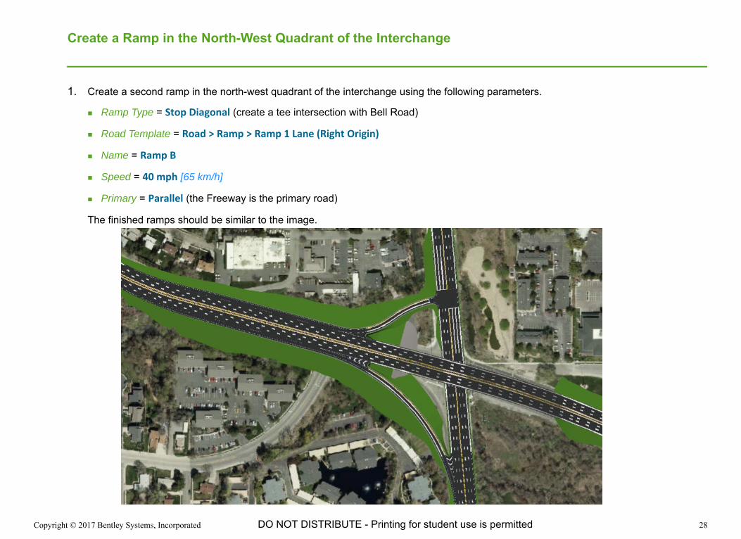
Create a Ramp in the North-West Quadrant of the Interchange
1. Create a second ramp in the north-west quadrant of the interchange using the following parameters.
Ramp Type = Stop Diagonal (create a tee intersection with Bell Road)
Road Template = Road > Ramp > Ramp 1 Lane (Right Origin)
Name = Ramp B
Speed = 40 mph [65 km/h]
Primary = Parallel (the Freeway is the primary road)
The finished ramps should be similar to the image.
Copyright © 2017 Bentley Systems, Incorporated 29DO NOT DISTRIBUTE - Printing for student use is permitted
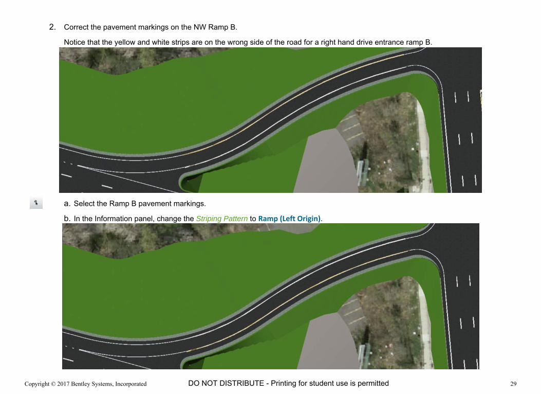
2. Correct the pavement markings on the NW Ramp B.
Notice that the yellow and white strips are on the wrong side of the road for a right hand drive entrance ramp B.
a. Select the Ramp B pavement markings.
b. In the Information panel, change the Striping Pattern to Ramp (Left Origin).

Copyright © 2017 Bentley Systems, Incorporated 30DO NOT DISTRIBUTE - Printing for student use is permitted
Create a Ramp in the South-East Quadrant of the Interchange
1. Create a Simple Direct Ramp D in the south-east quadrant of the interchange.
Experiment with different Radii to find and an acceptable solution.
Try a Compound curve instead of a simple curve.
The finished ramps should be similar to the image.
HINT: The image shows a compound curve using radii of 300ft - 400ft - 600ft [90m - 120m - 180m].

Copyright © 2017 Bentley Systems, Incorporated 31DO NOT DISTRIBUTE - Printing for student use is permitted
Exercise 4: Create Bridge Ramp
DescriptionIn this exercise you will learn how to import geometry, adjust template drops and create a bridge ramp.
Skills Taught Import alignment (alg file)
Define Roadway Template (Template Drop)
Create Bridge Ramp

Copyright © 2017 Bentley Systems, Incorporated 32DO NOT DISTRIBUTE - Printing for student use is permitted
Import Geometry
For the next exercise we will import the geometry for two roads east of the interchange from an alg file.
1. Set the Camera Orientation to the Top view.
2. Import the East Blvd and Rust Road alignments.
Note: This road geometry is begin imported from an ALG geometry file but it could also be manually created like in the previous exercise.
a. Select Import from the Backstage.
b. Select the Other tab.
c. Click Add Data and browse for the Geometry.alg file.
d. Set Import Alignments as to Road.
e. Set the Road Template to Road > 4 Lanes > Curb (4 Lanes).
f. Click Next.
g. Click Import.
h. Once completed, click Done.
Copyright © 2017 Bentley Systems, Incorporated 33DO NOT DISTRIBUTE - Printing for student use is permitted
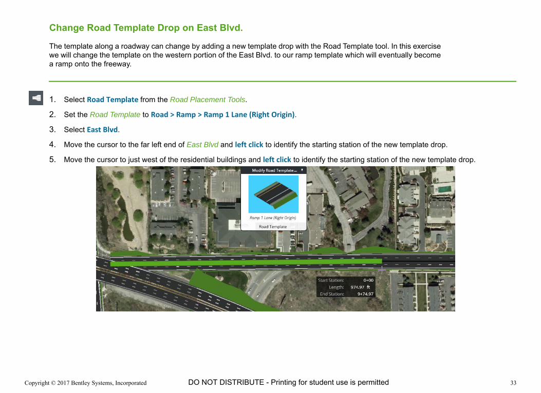
Change Road Template Drop on East Blvd.
The template along a roadway can change by adding a new template drop with the Road Template tool. In this exercise we will change the template on the western portion of the East Blvd. to our ramp template which will eventually become a ramp onto the freeway.
1. Select Road Template from the Road Placement Tools.
2. Set the Road Template to Road > Ramp > Ramp 1 Lane (Right Origin).
3. Select East Blvd.
4. Move the cursor to the far left end of East Blvd and left click to identify the starting station of the new template drop.
5. Move the cursor to just west of the residential buildings and left click to identify the starting station of the new template drop.
Copyright © 2017 Bentley Systems, Incorporated 34DO NOT DISTRIBUTE - Printing for student use is permitted
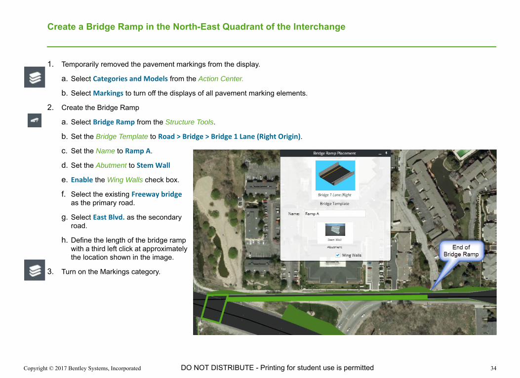
Create a Bridge Ramp in the North-East Quadrant of the Interchange
1. Temporarily removed the pavement markings from the display.
a. Select Categories and Models from the Action Center.
b. Select Markings to turn off the displays of all pavement marking elements.
2. Create the Bridge Ramp
a. Select Bridge Ramp from the Structure Tools.
b. Set the Bridge Template to Road > Bridge > Bridge 1 Lane (Right Origin).
c. Set the Name to Ramp A.
d. Set the Abutment to Stem Wall
e. Enable the Wing Walls check box.
f. Select the existing Freeway bridge as the primary road.
g. Select East Blvd. as the secondary road.
h. Define the length of the bridge ramp with a third left click at approximately the location shown in the image.
3. Turn on the Markings category.
Copyright © 2017 Bentley Systems, Incorporated 35DO NOT DISTRIBUTE - Printing for student use is permitted
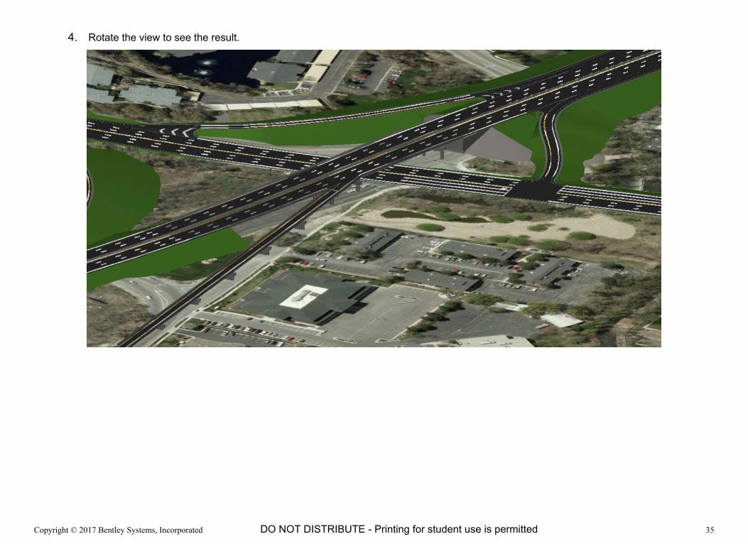
4. Rotate the view to see the result.

Copyright © 2017 Bentley Systems, Incorporated 36DO NOT DISTRIBUTE - Printing for student use is permitted
Exercise 5: Create a Roundabout
DescriptionIn this exercise you will learn how to create roundabout using the roundabout tool.
Skills Taught Roundabout Tool

Copyright © 2017 Bentley Systems, Incorporated 37DO NOT DISTRIBUTE - Printing for student use is permitted
Create a Roundabout
1. Set the Camera Orientation to the Top view.
2. Zoom to the intersection of the two four lane roads east of the interchange.
3. Select Roundabout from the Road Placement Tools.
4. Set the Inscribed Radius to 60 ft [18m].
5. Set the Circulating Width to 32 ft [10m].
6. Enable the Has Apron option.
7. Select East Blvd. (east-west road) as the Primary road.
A preview of the roundabout is displayed.
8. Select Rust Road (north-south road) as the Secondary road.
The proposed roundabout appears.
9. Right click to accept and create the roundabout.
Copyright © 2017 Bentley Systems, Incorporated 38DO NOT DISTRIBUTE - Printing for student use is permitted
Exercise 6: Adding City Furniture
DescriptionIn this exercise you will learn how to place lighting and the guardrail in the model.
Skills Taught Place Furniture Along Path
Place Linear Furniture

Copyright © 2017 Bentley Systems, Incorporated 39DO NOT DISTRIBUTE - Printing for student use is permitted
Place the Lighting
1. Set the Camera Orientation to the Top view.
2. Select Furniture Along a Path from the Furniture Tools.
3. Set Furniture to Street Lights > Lamp_double_9X2,7.
4. Set the Spacing to 150ft [20m].
5. Set the Angle from alignment to 0° 00' 00".
6. Clear the Force last insertion option.
7. Place the lights by Start and End Station along the centerline of the entire length of the Freeway.
a. Start Station = Position the cursor near the beginning of the Freeway centerline and at an Offset = 0 and Left Click.
b. End Station = Position the cursor near the end of the Freeway centerline and at an Offset = 0 and Left Click.
TIP: The station and offset can be adjusted in the after the furniture is placed. Zoom to the start or end position and select the furniture to show the station manipulator. Select a second time to show the offset manipulator.
8. Right Click to create the lights.
9. Exit the command by clicking on the Element Selection tool.
10. Rotate the view to review the street lights.

Copyright © 2017 Bentley Systems, Incorporated 40DO NOT DISTRIBUTE - Printing for student use is permitted
Place Guardrail
1. Set the Camera Orientation to the Top view.
2. Select Linear Furniture from the Furniture Tools.
3. Set Furniture to Guardrail Type B (Steel Post).
4. Set the Spacing to 6.25ft [2m].
5. Set the Angle to 0° 00' 00".
6. Clear the Force last insertion option check box.
7. Place the first Guardrail on the north side of the Freeway between the ramp and the bridge.
TIP: To ensure the rail and posts are drawn on the correct side the guardrail should be created in the direction of traffic.
a. Click at the location to start the guardrail.
This position does not need to be exact. You will adjust it in the next step.
b. Click at the location to end the guardrail.
c. Right Click to create the guardrail.
8. Adjust the guardrail location.
a. Select the guardrail.
b. Use the station manipulators to adjust the start and end stations of the guardrail.
c. Select the guardrail again to change from the station to the offset manipulators.
d. Use the offset manipulator or text fields to place the guardrail at a -42.5ft [-13m] offset.
TIP: The offset can also be edited in the Properties Panel.
Copyright © 2017 Bentley Systems, Incorporated 41DO NOT DISTRIBUTE - Printing for student use is permitted
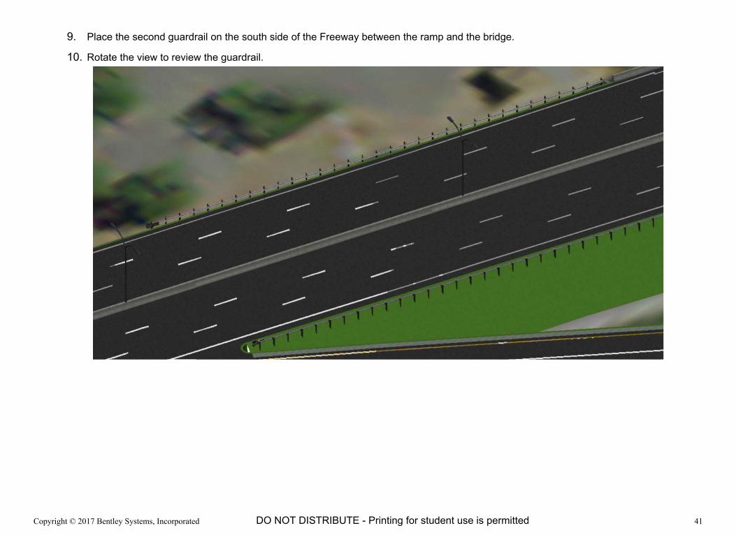
9. Place the second guardrail on the south side of the Freeway between the ramp and the bridge.
10. Rotate the view to review the guardrail.

Copyright © 2017 Bentley Systems, Incorporated 42DO NOT DISTRIBUTE - Printing for student use is permitted
Exercise 7: Adding Street Markings
DescriptionIn this exercise you will learn how to place street markings.
Skills Taught Place street markings

Copyright © 2017 Bentley Systems, Incorporated 43DO NOT DISTRIBUTE - Printing for student use is permitted
Place Left Turn Street Marking at the Intersection
1. Set the Camera Orientation to the Top view.
2. Zoom to the intersection at the end of Ramp B.
3. Select Street Marking from the Marking Tools.
4. Set the Street Marking Template to Left Turn Lane-Use.
5. Left Click to position the marking in the lane as shown in the image.
6. Once the pavement marking is located, move the mouse to rotate the marking to the desired orientation and Left Click to confirm the placement.
7. Press the Esc key to exit the command.
TIP: To edit the marking, use the Selection tool and pick the marking to be edited. Use the arrow manipulators to move the marking along the alignment. To move the marking perpendicular to the alignment click twice on it and use the arrow to move it.

Copyright © 2017 Bentley Systems, Incorporated 44DO NOT DISTRIBUTE - Printing for student use is permitted
Exercise 8: Quantities and Cost
DescriptionIn this exercise you will learn how to view, edit, and export cost and quantity information.
Skills Taught View Cost and Quantity
Export Cost and Quantities to a Microsoft Excel file
Setup how cost and quantities are computed.

Copyright © 2017 Bentley Systems, Incorporated 45DO NOT DISTRIBUTE - Printing for student use is permitted
Review Estimated Cost of Concept Model
1. Select Concept Estimated Cost from the Action Center.
The estimated costs are updated by clicking the Refresh tool. Whenever something changes in the design, it is necessary to use the Refresh tool to update the estimated costs.
2. Click Refresh to update the concept estimated costs.
3. Click Detailed Quantities and Cost Report to view a more detailed report.
4. This detailed report can be exported to Microsoft Excel by clicking Export to XLSX.
5. Click < in the upper left corner to return to the Conceptualize view.
6. Minimize the Action Center.
Copyright © 2017 Bentley Systems, Incorporated 46DO NOT DISTRIBUTE - Printing for student use is permitted
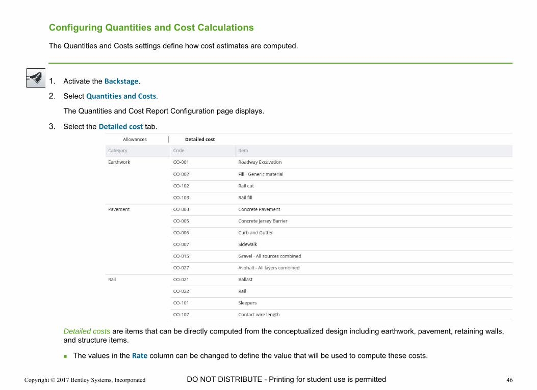
Configuring Quantities and Cost Calculations
The Quantities and Costs settings define how cost estimates are computed.
1. Activate the Backstage.
2. Select Quantities and Costs.
The Quantities and Cost Report Configuration page displays.
3. Select the Detailed cost tab.
Detailed costs are items that can be directly computed from the conceptualized design including earthwork, pavement, retaining walls, and structure items.
The values in the Rate column can be changed to define the value that will be used to compute these costs.

Copyright © 2017 Bentley Systems, Incorporated 47DO NOT DISTRIBUTE - Printing for student use is permitted
4. Select the Allowances tab.
Allowance costs are for items that are not specifically modeled in the concept but are known to be part of the cost of a project. They are calculated as a percentage of the total Earthwork and Pavement (everything except Structural) detailed item costs.
For example, if the estimated cost of the Earthwork and Pavement for the concept is $1,000,000, the Drainage allowance would be $81,100 ($1,000,000 x 8.11% = $81,100)
The values in the Rate column can be changed to define the percentage rate used to calculate the allowance.
The Use Allowance column determines if the allowance item is included in the cost estimate. Only those allowances that are enabled are included in the cost estimate.
5. To return to the modeling environment.
a. Select the Backstage.
b. Select Conceptualize.

Copyright © 2017 Bentley Systems, Incorporated 48DO NOT DISTRIBUTE - Printing for student use is permitted
Exercise 9: Creating and Modifying Templates
DescriptionIn this exercise you will learn how to edit existing templates and how to create a new one.
Skills Taught Create new template
Edit a template

Copyright © 2017 Bentley Systems, Incorporated 49DO NOT DISTRIBUTE - Printing for student use is permitted
Create a New Template
1. Activate the Backstage.
2. Select Templates.
The Template Manager dialog appears.
3. Create a new road template.
a. Click New.
b. Set the Template Name to Bell Road.
c. Set the Description to Training Template.
d. Set the Template Type to Road Template.
e. Click OK.
The new template is created and the Template Editor dialog appears.
4. Add a lane to the template
a. Select the Image for the Lane component.
HINT: It may be necessary to scroll the components list to get to the Shoulder components near the bottom of the list.
b. Select Mirror Component to place a lane on each side of the template at the same time.
c. Click at the 0,0 position to define the location of the new lanes.
Copyright © 2017 Bentley Systems, Incorporated 50DO NOT DISTRIBUTE - Printing for student use is permitted
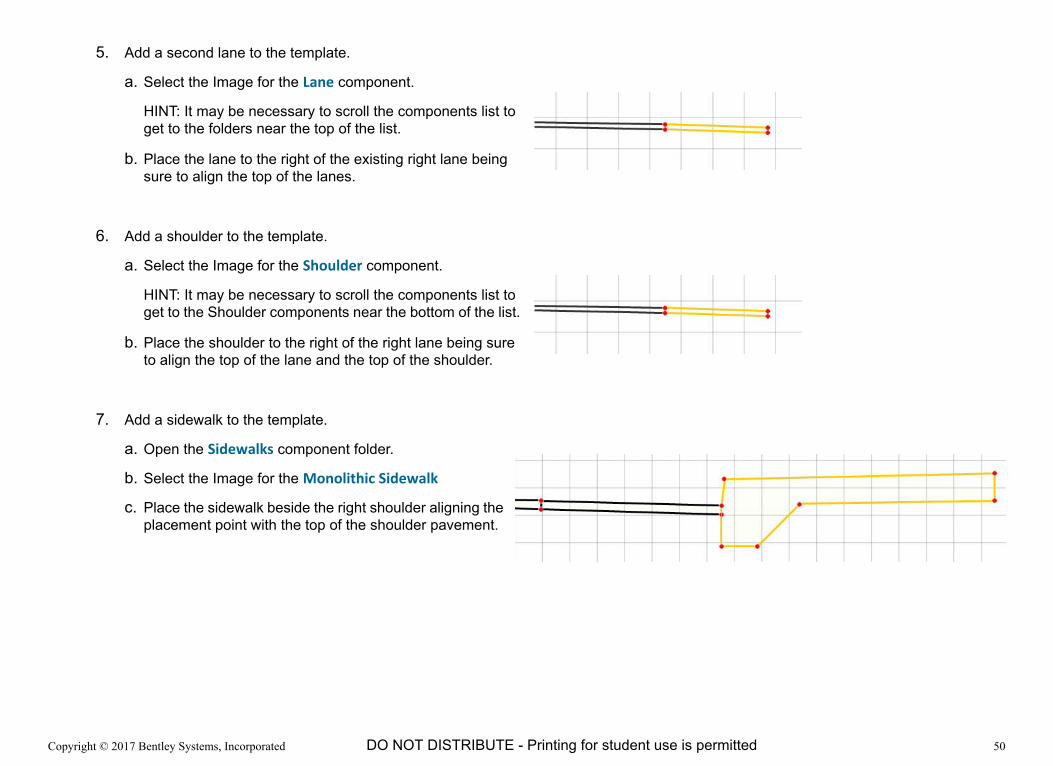
5. Add a second lane to the template.
a. Select the Image for the Lane component.
HINT: It may be necessary to scroll the components list to get to the folders near the top of the list.
b. Place the lane to the right of the existing right lane being sure to align the top of the lanes.
6. Add a shoulder to the template.
a. Select the Image for the Shoulder component.
HINT: It may be necessary to scroll the components list to get to the Shoulder components near the bottom of the list.
b. Place the shoulder to the right of the right lane being sure to align the top of the lane and the top of the shoulder.
7. Add a sidewalk to the template.
a. Open the Sidewalks component folder.
b. Select the Image for the Monolithic Sidewalk
c. Place the sidewalk beside the right shoulder aligning the placement point with the top of the shoulder pavement.

Copyright © 2017 Bentley Systems, Incorporated 51DO NOT DISTRIBUTE - Printing for student use is permitted
8. Return to the Components folder by selecting Components.
HINT: If Components is not visible, move the slide bar to the left.
9. Select the Segment component and place it beside the right sidewalk.
10. Select the Cut component from the End Conditions folder and place it at the end of the right segment.
11. Select the Fill component from the End Conditions folder and place it at the end of the right segment.
12. Right click to stop the creation.
13. Click Save to finish the creation of the new template.

Copyright © 2017 Bentley Systems, Incorporated 52DO NOT DISTRIBUTE - Printing for student use is permitted
Edit an Existing Template
1. Hover the mouse over the Bell Road template and select Edit Template.
The Template Editor appears.
2. Select the Lane.
The Grid dialog appears below the template.
3. Change the dimensions of all four Lanes to the following values if they are not already set.
Width: 12.00 ft [3.6m]
Height: 10.00 in [250mm]
4. Click Save to complete the edit.
5. To return to the modeling environment.
a. Select the Backstage.
b. Select Conceptualize.
Copyright © 2017 Bentley Systems, Incorporated 53DO NOT DISTRIBUTE - Printing for student use is permitted
Appendix: Creating and Storing Files
DescriptionThis section teaches how to create a new file and import data. You will also learn how to use CONNECTed Projects with ConceptStation.
Skills Taught Create a new file
Import data from a shp and alg files
CONNECT Project

Copyright © 2017 Bentley Systems, Incorporated 54DO NOT DISTRIBUTE - Printing for student use is permitted
Creating a New File
1. From the Open page, click New.
2. Set the File Location to where the new file will be created.
3. Type the Name of the new file.
4. Define the project area.
a. Zoom into the area on the map or use the Search Tool in the map view to quickly zoom to a city.
b. By default the terrain and raster photo will cover the area of the map or a sub area can be defined using Define Concept Location.
c. Select the proper Coordinate System for the project.
d. An existing ConceptStation file can be used as a seed when creating a new file. The benefit of using a seed is that the new file will inherit the Concept Location, Coordinate System and Settings such as templates of the original file.
e. Click Create to create the new file and begin importing context data.
The Context Data Import dialog appears.

Copyright © 2017 Bentley Systems, Incorporated 55DO NOT DISTRIBUTE - Printing for student use is permitted
5. Import Context Data
a. Select Use GeoCoordination Services.
The GeoCoordination Services page displays.
b. Select the Data Classes to be imported. At a minimum this should include the Terrain but the aerial imagery can also be very useful.
The Results page appears showing the data that will be downloaded.
c. Set the Imagery Resolution. Higher resolutions take longer to download and take more resources when used.
NOTE: The data downloaded from the GeoCoordination Services can be found in the GeoCoordination Services Download path defined in the Backstage > Settings > GeoCoordination Services section. It can be useful to keep a copy of this data for future use. This data can then simply be imported in OpenRoads ConceptStation without having to wait for the download process.

Copyright © 2017 Bentley Systems, Incorporated 56DO NOT DISTRIBUTE - Printing for student use is permitted
Importing Other Data
Importing Other Data such as MicroStation graphics, geometry from an alg file and GIS data from shp files.
1. From the Backstage, select Import.
2. Select the Other tab.
3. Click Add Data.
4. Browse to the data file. The following file types can be imported.
Open Street Map Files (*.osm)
Design Files (*.dgn)
Shapefiles (*.shp)
Civil Geometry Files (*.alg)
ESRI File Geodatabase (*.gdb)
LandXML Files (*.xml)
5. Click Import.
Copyright © 2017 Bentley Systems, Incorporated 57DO NOT DISTRIBUTE - Printing for student use is permitted
Bentley CONNECT Profile
A Bentley CONNECT Profile gives you access to a range of information, support, learning and project services including the ability to use the GeoCoordination Services and to associate ConceptStation files with CONNECT Projects.
When you are signed in to the CONNECTION client when you launch OpenRoads ConceptStation, you are automatically signed in.
Your name appears in the upper left corner of the Backstage when you are signed in.
When you are not signed in, you can sign in or create a new Bentley CONNECT profile as described below.
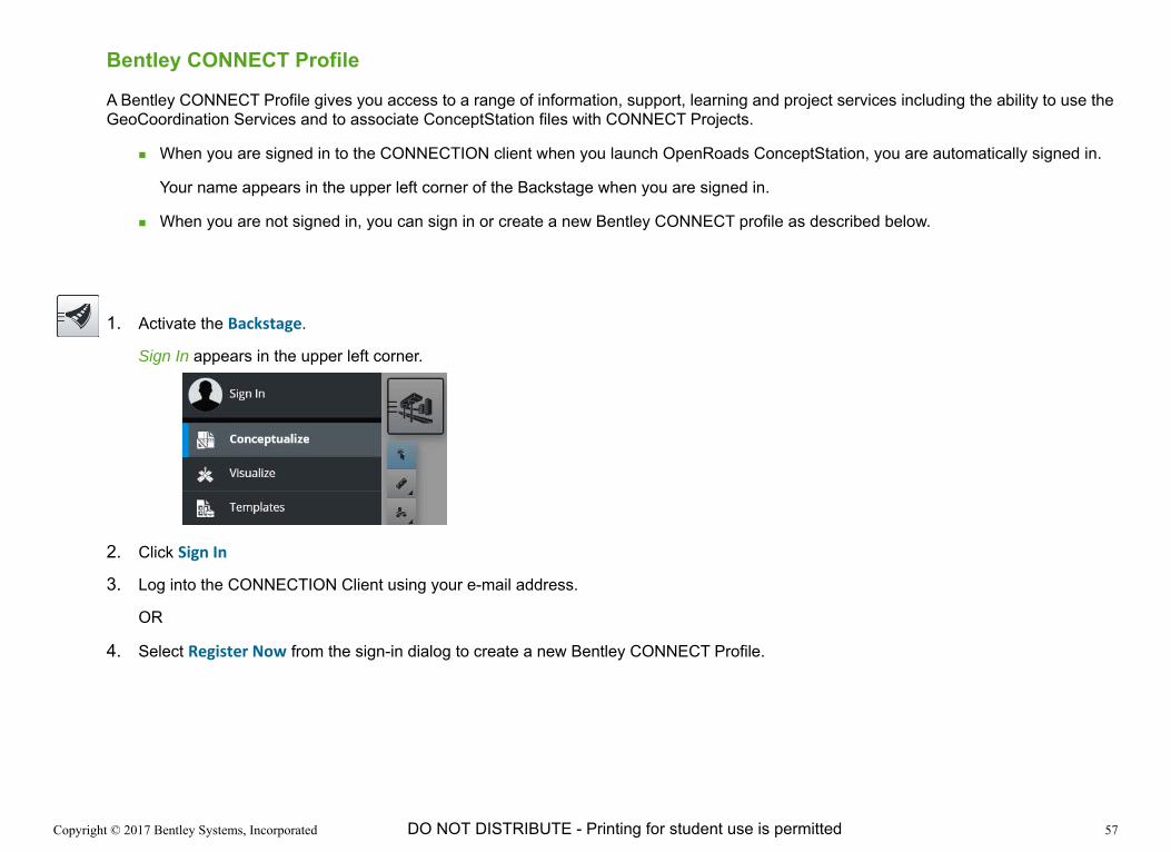
1. Activate the Backstage.
Sign In appears in the upper left corner.
2. Click Sign In
3. Log into the CONNECTION Client using your e-mail address.
OR
4. Select Register Now from the sign-in dialog to create a new Bentley CONNECT Profile.
Copyright © 2017 Bentley Systems, Incorporated 58DO NOT DISTRIBUTE - Printing for student use is permitted
Associating a ConceptStation file with a Bentley CONNECT Project
ConceptStation files can be associated with Bentley CONNECT projects for improved collaboration and visibility throughout your entire project team.
1. Activate the Backstage.
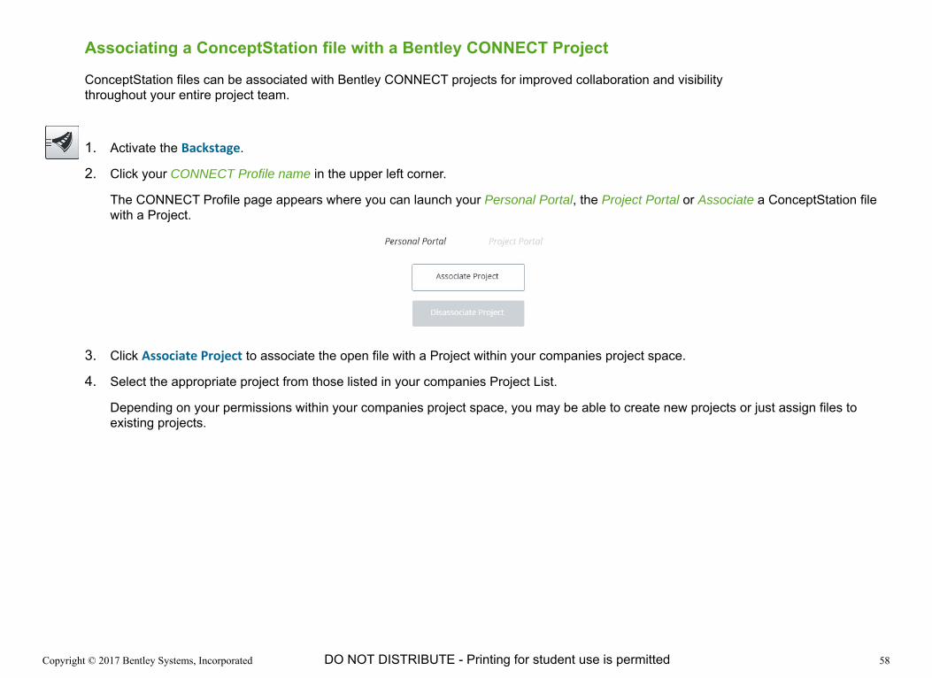
2. Click your CONNECT Profile name in the upper left corner.
The CONNECT Profile page appears where you can launch your Personal Portal, the Project Portal or Associate a ConceptStation file with a Project.
3. Click Associate Project to associate the open file with a Project within your companies project space.
4. Select the appropriate project from those listed in your companies Project List.
Depending on your permissions within your companies project space, you may be able to create new projects or just assign files to existing projects.