Embed Size (px)
Citation preview
1Carlo Gavazzi LTD
RSBD
RSBD DS ENG22/11/2018
Three-Phase Scroll Compressor Soft Starter
Description
RSBD is an easy to use soft starter for scroll compressors up to 95 Arms nominal current.The units are equipped with a patented auto-adaptive algorithm that automatically adapts itself to the specific compressor it is controlling ensuring that an optimum inrush current reduction is achieved.RSBD is a 2-phase controlled solution and is internally bypassed - resulting in less heat dissipation inside the panel.Short Circuit and Overload protection are not provided with the controller and must be procured separately.
Benefits• Easy to use. The RSBD is equipped with a self-learning
algorithm that automatically adjusts the start parameters to reduce the compressor starting current.
• Fast installation and set-up. No settings are required.• Compact dimensions. 12 - 45 Arms in 45 mm wide
housing, 55 - 95 Arms in 75 mm wide housing.• Guided model selection. Easy to use online selection
tool to select the appropriate soft starter model depending on the compressor brand/model. Go to http://gavazziautomation.com/nsc/HQ/EN/soft_starters.
• Tamper proof. No user adjustments are available. RSBD automatically adjusts its internal parameters to ensure optimal starting at any condition.
• Adjusts to load requirements. The built-in HP function ensures that the compressor starts in < 1 second even under high pressure difference during start.
Main features
Applications
Scroll compressors, heat pumps, chiller, air-conditioning units
• Self-learning algorithm adjusts start parameters according to load• No user adjustments required• Limits starting current of 3 phase compressors
2Carlo Gavazzi LTD
RSBD
22/11/2018
References
Order code
RSBD V 61HP
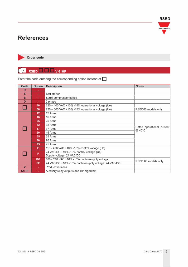
Enter the code entering the corresponding option instead of
Code Option Description NotesR -S - Soft starterB - Scroll compressor seriesD - 2 phase
40 220 – 400 VAC +10% -15% operational voltage (Ue)60 220 – 600 VAC +10% -15% operational voltage (Ue) RSBD60 models only12 12 Arms
Rated operational current @ 40°C
16 16 Arms25 25 Arms32 32 Arms37 37 Arms50 45 Arms55 55 Arms70 70 Arms95 95 ArmsE 110 - 400 VAC +10% -15% control voltage (Uc)
F 24 VAC/DC +10% -10% control voltage (Uc)Supply voltage: 24 VAC/DC
GG 100 - 240 VAC +10% -15% control/supply voltage RSBD 60 models onlyFF 24 VAC/DC +10% -10% control/supply voltage: 24 VAC/DCV - Product versions
61HP - Auxiliary relay outputs and HP algorithm
RSBD DS ENG
3Carlo Gavazzi LTD
RSBD
22/11/2018
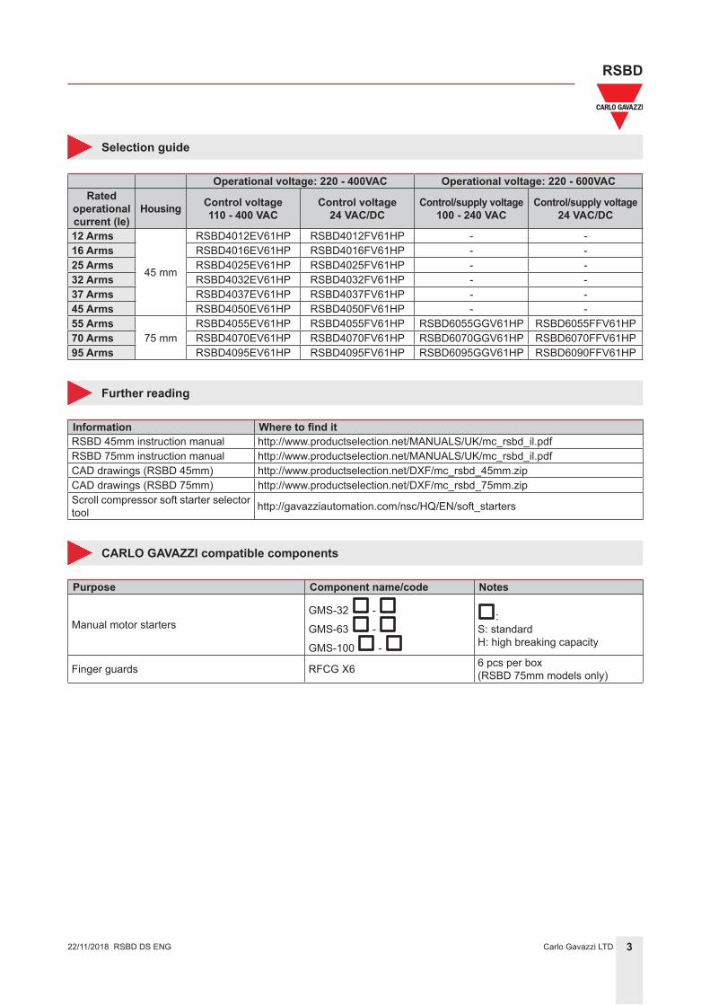
Selection guide
Operational voltage: 220 - 400VAC Operational voltage: 220 - 600VACRated
operational current (Ie)
Housing Control voltage110 - 400 VAC
Control voltage24 VAC/DC
Control/supply voltage100 - 240 VAC
Control/supply voltage24 VAC/DC
12 Arms
45 mm
RSBD4012EV61HP RSBD4012FV61HP - -16 Arms RSBD4016EV61HP RSBD4016FV61HP - -25 Arms RSBD4025EV61HP RSBD4025FV61HP - -32 Arms RSBD4032EV61HP RSBD4032FV61HP - -37 Arms RSBD4037EV61HP RSBD4037FV61HP - -45 Arms RSBD4050EV61HP RSBD4050FV61HP - -55 Arms
75 mmRSBD4055EV61HP RSBD4055FV61HP RSBD6055GGV61HP RSBD6055FFV61HP
70 Arms RSBD4070EV61HP RSBD4070FV61HP RSBD6070GGV61HP RSBD6070FFV61HP95 Arms RSBD4095EV61HP RSBD4095FV61HP RSBD6095GGV61HP RSBD6090FFV61HP
Further reading
Information Where to find itRSBD 45mm instruction manual http://www.productselection.net/MANUALS/UK/mc_rsbd_il.pdfRSBD 75mm instruction manual http://www.productselection.net/MANUALS/UK/mc_rsbd_il.pdfCAD drawings (RSBD 45mm) http://www.productselection.net/DXF/mc_rsbd_45mm.zipCAD drawings (RSBD 75mm) http://www.productselection.net/DXF/mc_rsbd_75mm.zipScroll compressor soft starter selector tool http://gavazziautomation.com/nsc/HQ/EN/soft_starters
CARLO GAVAZZI compatible components
Purpose Component name/code Notes
Manual motor startersGMS-32 -
GMS-63 -
GMS-100 -
:S: standardH: high breaking capacity
Finger guards RFCG X6 6 pcs per box(RSBD 75mm models only)
RSBD DS ENG
4Carlo Gavazzi LTD
RSBD
RSGD 45_ 75mm DS ENG22/11/2018 4Carlo Gavazzi LTD
RSBD
22/11/2018
Structure
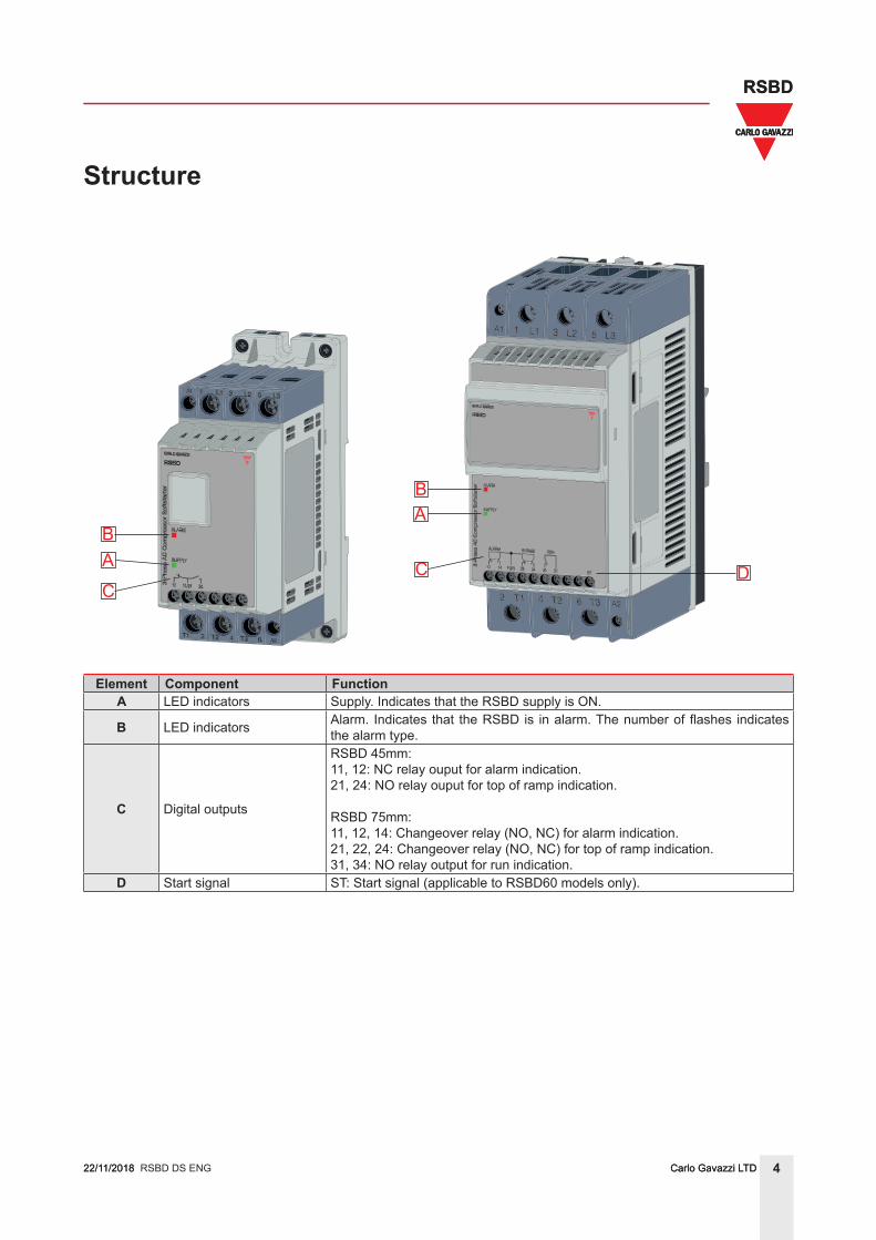
Element Component FunctionA LED indicators Supply. Indicates that the RSBD supply is ON.
B LED indicators Alarm. Indicates that the RSBD is in alarm. The number of flashes indicates the alarm type.
C Digital outputs
RSBD 45mm:11, 12: NC relay ouput for alarm indication.21, 24: NO relay ouput for top of ramp indication.
RSBD 75mm:11, 12, 14: Changeover relay (NO, NC) for alarm indication.21, 22, 24: Changeover relay (NO, NC) for top of ramp indication.31, 34: NO relay output for run indication.
D Start signal ST: Start signal (applicable to RSBD60 models only).
RSBD DS ENG
AB
C
AB
C D
5Carlo Gavazzi LTD
RSBD
RSGD 45_ 75mm DS ENG22/11/2018 5Carlo Gavazzi LTD
RSBD
22/11/2018
Mode of operation
• RSBD series of soft starters includes an innovative auto-adaptive algorithm (Patented) that limits the com-pressor starting current and minimises current unbalance. Appropriate parameters are automatically set by RSBD in order to achieve an optimum inrush current reduction whilst maintaining a ramp-up time < 1 sec This feature is active at every compressor start to ensure that the RSBD adapts its parameters according to the load requirements at different operating conditions.
• At the very first start, the RSBD will start the compressor with the default current limit setting.
Note: The default current limit is equal to 3.5 x Ie (where Ie = soft starter rated current). Depending on the val-ues of specific parameters, that are automatically measured by RSBD, it will adjust the current limit setting to a lower value. This new self-learned current limit setpoint will then be used by RSBD during the subsequent start.
• During the ramp-up sequence, the RSBD will check if the compressor is rotating. If the RSBD finds the compressor in locked rotor condition, it will trigger the HP function. During the HP sequence, the RSBD will gradually increase the current limit setpoint. The maximum value is ≤ 3.5 x Ie.
Note: Even during HP mode of operation the ramp-up time will be limited to a maximum of 1 sec. If the com-pressor does not reach full speed during a maximum of 1 sec, the RSBD will trigger the End of ramp alarm (5 flashes) and will go in alarm state.
• RSBD uses a two-phase control strategy with two anti-parallel thyristors across L1-T1 and L3-T3. Phase L2-T2 is the uncontrolled phase. During every start, RSBD measures a number of parameters and dynamically adjusts the starting parameters to minimise the current unbalance in the phase L2-T2 resulting in a smoother starting performance of the compressor.
RSBD DS ENG
Auto Adaptive Algorithm (Patented)
High pressure (HP) function
First start of RSBD
Current balancing
6Carlo Gavazzi LTD
RSBD
RSGD 45_ 75mm DS ENG22/11/2018 6Carlo Gavazzi LTD
RSBD
22/11/2018
Features
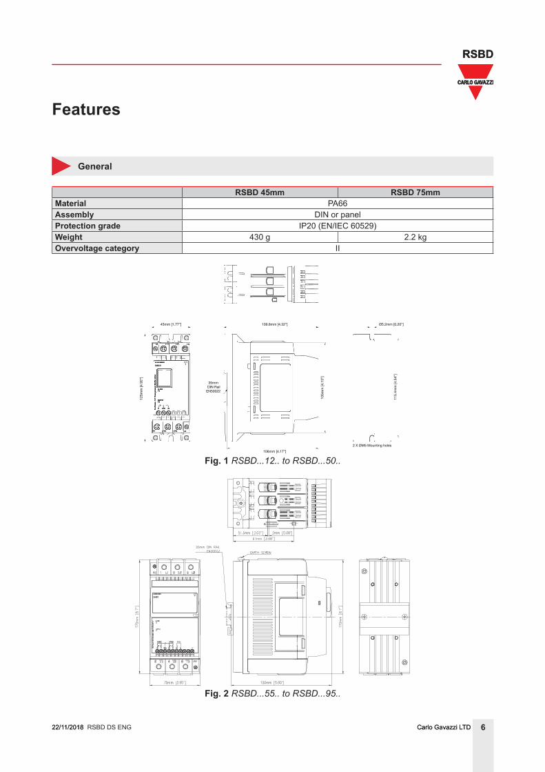
General
RSBD 45mm RSBD 75mmMaterial PA66Assembly DIN or panelProtection grade IP20 (EN/IEC 60529)Weight 430 g 2.2 kgOvervoltage category II
35mm DIN Rail
EN50022
125m
m [4
.92”
]
45mm [1.77”] 109.8mm [4.32”]
106mm [4.17”]
105m
m [4
.13”
]Ø5.2mm [0.20”]
2 X ØM5 Mounting holes
115.
4mm
[4.5
4”]
Fig. 1 RSBD...12.. to RSBD...50..
Fig. 2 RSBD...55.. to RSBD...95..
RSBD DS ENG
7Carlo Gavazzi LTD
RSBD
22/11/2018
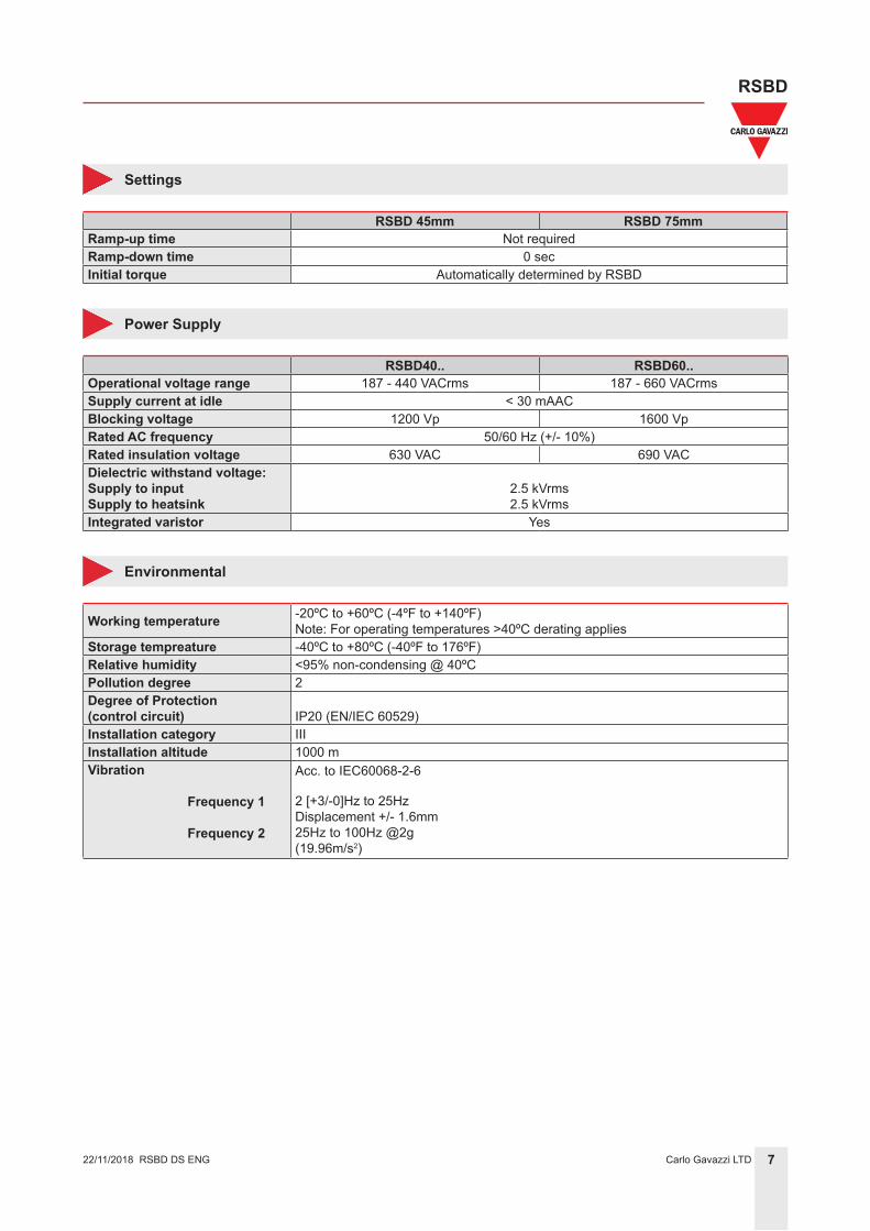
Settings
RSBD 45mm RSBD 75mmRamp-up time Not requiredRamp-down time 0 secInitial torque Automatically determined by RSBD
Power Supply
RSBD40.. RSBD60..Operational voltage range 187 - 440 VACrms 187 - 660 VACrmsSupply current at idle < 30 mAACBlocking voltage 1200 Vp 1600 VpRated AC frequency 50/60 Hz (+/- 10%)Rated insulation voltage 630 VAC 690 VACDielectric withstand voltage:Supply to inputSupply to heatsink
2.5 kVrms2.5 kVrms
Integrated varistor Yes
Environmental
Working temperature -20ºC to +60ºC (-4ºF to +140ºF) Note: For operating temperatures >40ºC derating applies
Storage tempreature -40ºC to +80ºC (-40ºF to 176ºF)Relative humidity <95% non-condensing @ 40ºCPollution degree 2Degree of Protection(control circuit) IP20 (EN/IEC 60529)Installation category IIIInstallation altitude 1000 mVibration
Frequency 1
Frequency 2
Acc. to IEC60068-2-6
2 [+3/-0]Hz to 25HzDisplacement +/- 1.6mm25Hz to 100Hz @2g(19.96m/s2)
RSBD DS ENG
8Carlo Gavazzi LTD
RSBD
22/11/2018
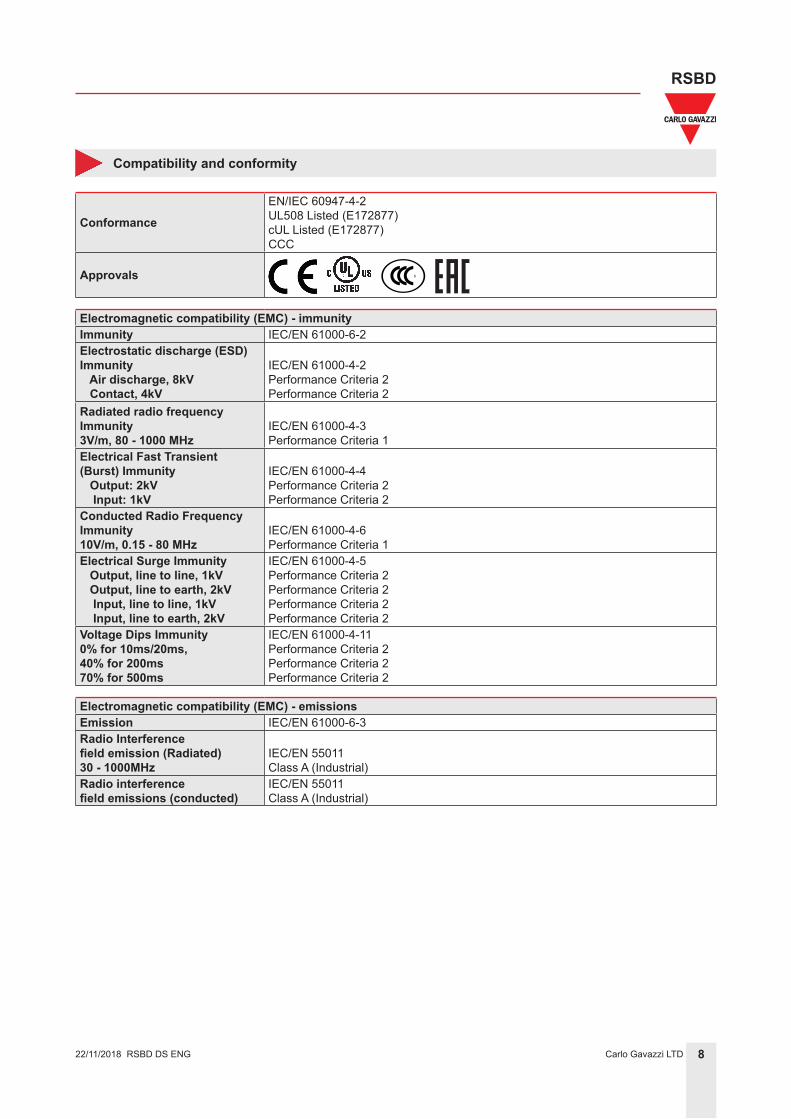
Compatibility and conformity
Conformance
EN/IEC 60947-4-2UL508 Listed (E172877)cUL Listed (E172877)CCC
Approvals
Electromagnetic compatibility (EMC) - immunityImmunity IEC/EN 61000-6-2Electrostatic discharge (ESD)Immunity Air discharge, 8kV Contact, 4kV
IEC/EN 61000-4-2Performance Criteria 2Performance Criteria 2
Radiated radio frequencyImmunity3V/m, 80 - 1000 MHz
IEC/EN 61000-4-3Performance Criteria 1
Electrical Fast Transient(Burst) Immunity Output: 2kV Input: 1kV
IEC/EN 61000-4-4Performance Criteria 2Performance Criteria 2
Conducted Radio FrequencyImmunity10V/m, 0.15 - 80 MHz
IEC/EN 61000-4-6Performance Criteria 1
Electrical Surge Immunity Output, line to line, 1kV Output, line to earth, 2kV Input, line to line, 1kV Input, line to earth, 2kV
IEC/EN 61000-4-5Performance Criteria 2Performance Criteria 2Performance Criteria 2Performance Criteria 2
Voltage Dips Immunity0% for 10ms/20ms,40% for 200ms70% for 500ms
IEC/EN 61000-4-11Performance Criteria 2Performance Criteria 2Performance Criteria 2
Electromagnetic compatibility (EMC) - emissionsEmission IEC/EN 61000-6-3Radio Interferencefield emission (Radiated)30 - 1000MHz
IEC/EN 55011Class A (Industrial)
Radio interferencefield emissions (conducted)
IEC/EN 55011Class A (Industrial)
RSBD DS ENG
9Carlo Gavazzi LTD
RSBD
22/11/2018
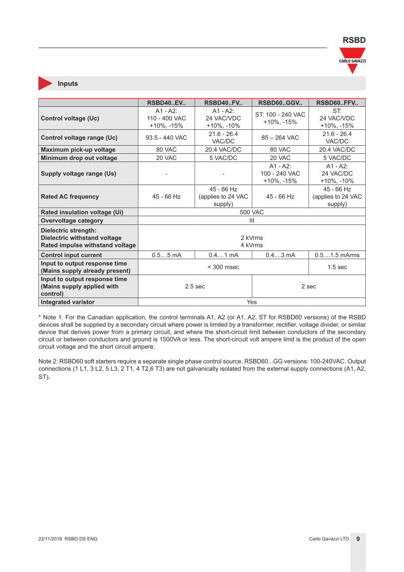
Inputs
RSBD40..EV.. RSBD40..FV.. RSBD60..GGV.. RSBD60..FFV..
Control voltage (Uc)A1 - A2:
110 - 400 VAC+10%, -15%
A1 - A2: 24 VAC/VDC+10%, -10%
ST: 100 - 240 VAC+10%, -15%
ST:24 VAC/VDC+10%, -15%
Control voltage range (Uc) 93.5 - 440 VAC 21.6 - 26.4 VAC/DC 85 – 264 VAC 21.6 - 26.4
VAC/DCMaximum pick-up voltage 80 VAC 20.4 VAC/DC 80 VAC 20.4 VAC/DCMinimum drop out voltage 20 VAC 5 VAC/DC 20 VAC 5 VAC/DC
Supply voltage range (Us) - -A1 - A2:
100 - 240 VAC+10%, -15%
A1 - A2:24 VAC/DC+10%, -10%
Rated AC frequency 45 - 66 Hz45 - 66 Hz
(applies to 24 VAC supply)
45 - 66 Hz45 - 66 Hz
(applies to 24 VAC supply)
Rated insulation voltage (Ui) 500 VACOvervoltage category IIIDielectric strength:Dielectric withstand voltageRated impulse withstand voltage
2 kVrms4 kVrms
Control input current 0.5....5 mA 0.4....1 mA 0.4....3 mA 0.5....1.5 mArmsInput to output response time (Mains supply already present) < 300 msec 1.5 sec
Input to output response time (Mains supply applied with control)
2.5 sec 2 sec
Integrated varistor Yes
* Note 1: For the Canadian application, the control terminals A1, A2 (or A1, A2, ST for RSBD60 versions) of the RSBD devices shall be supplied by a secondary circuit where power is limited by a transformer, rectifier, voltage divider, or similar device that derives power from a primary circuit, and where the short-circuit limit between conductors of the secondary circuit or between conductors and ground is 1500VA or less. The short-circuit volt ampere limit is the product of the open circuit voltage and the short circuit ampere.
Note 2: RSBD60 soft starters require a separate single phase control source. RSBD60...GG versions: 100-240VAC. Output connections (1 L1, 3 L2, 5 L3, 2 T1, 4 T2,6 T3) are not galvanically isolated from the external supply connections (A1, A2, ST).
RSBD DS ENG
10Carlo Gavazzi LTD
RSBD
22/11/2018
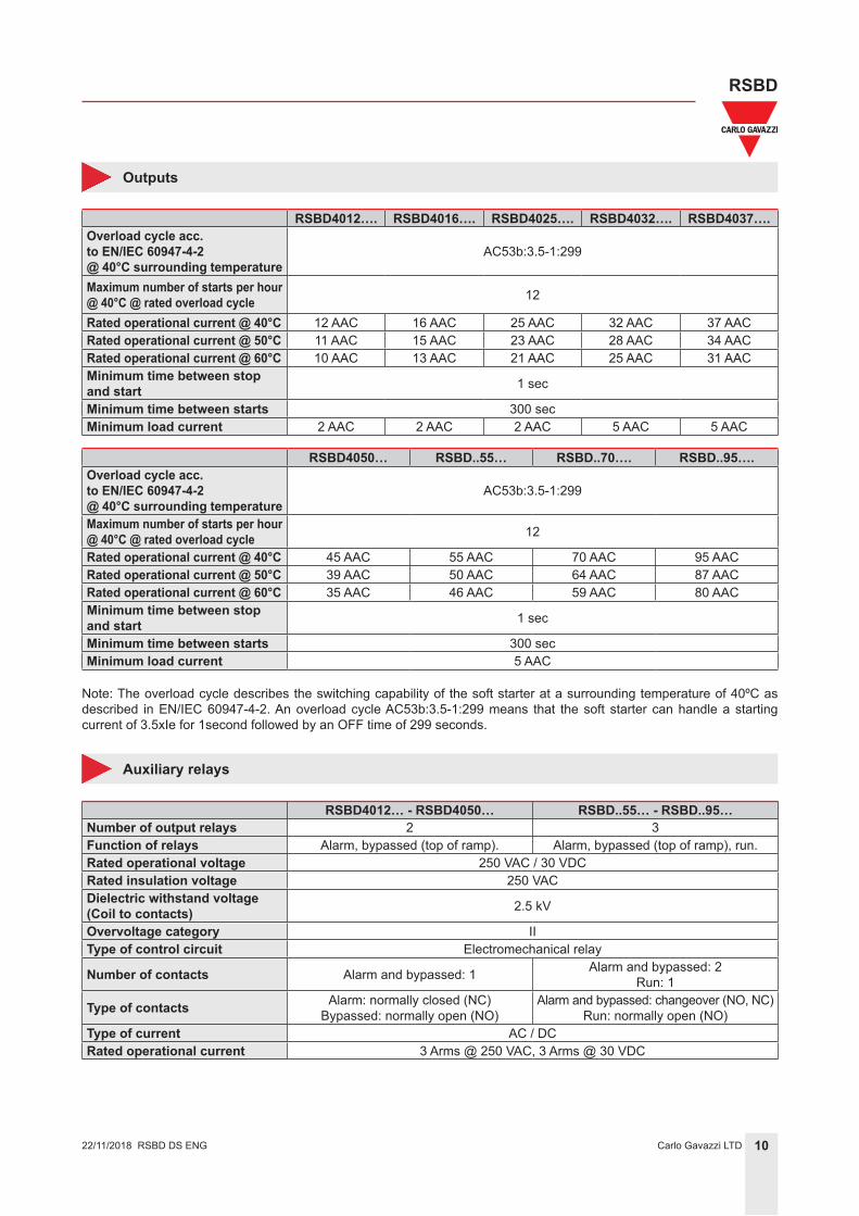
Outputs
RSBD4012…. RSBD4016…. RSBD4025…. RSBD4032…. RSBD4037….Overload cycle acc.to EN/IEC 60947-4-2@ 40°C surrounding temperature
AC53b:3.5-1:299
Maximum number of starts per hour @ 40°C @ rated overload cycle 12
Rated operational current @ 40°C 12 AAC 16 AAC 25 AAC 32 AAC 37 AACRated operational current @ 50°C 11 AAC 15 AAC 23 AAC 28 AAC 34 AACRated operational current @ 60°C 10 AAC 13 AAC 21 AAC 25 AAC 31 AACMinimum time between stop and start 1 sec
Minimum time between starts 300 secMinimum load current 2 AAC 2 AAC 2 AAC 5 AAC 5 AAC
RSBD4050… RSBD..55… RSBD..70…. RSBD..95….Overload cycle acc.to EN/IEC 60947-4-2@ 40°C surrounding temperature
AC53b:3.5-1:299
Maximum number of starts per hour @ 40°C @ rated overload cycle 12
Rated operational current @ 40°C 45 AAC 55 AAC 70 AAC 95 AACRated operational current @ 50°C 39 AAC 50 AAC 64 AAC 87 AACRated operational current @ 60°C 35 AAC 46 AAC 59 AAC 80 AACMinimum time between stop and start 1 sec
Minimum time between starts 300 secMinimum load current 5 AAC
Note: The overload cycle describes the switching capability of the soft starter at a surrounding temperature of 40ºC as described in EN/IEC 60947-4-2. An overload cycle AC53b:3.5-1:299 means that the soft starter can handle a starting current of 3.5xIe for 1second followed by an OFF time of 299 seconds.
Auxiliary relays
RSBD4012… - RSBD4050… RSBD..55… - RSBD..95…Number of output relays 2 3Function of relays Alarm, bypassed (top of ramp). Alarm, bypassed (top of ramp), run.Rated operational voltage 250 VAC / 30 VDCRated insulation voltage 250 VACDielectric withstand voltage(Coil to contacts) 2.5 kV
Overvoltage category IIType of control circuit Electromechanical relay
Number of contacts Alarm and bypassed: 1 Alarm and bypassed: 2Run: 1
Type of contacts Alarm: normally closed (NC)Bypassed: normally open (NO)
Alarm and bypassed: changeover (NO, NC)Run: normally open (NO)
Type of current AC / DCRated operational current 3 Arms @ 250 VAC, 3 Arms @ 30 VDC
RSBD DS ENG
11Carlo Gavazzi LTD
RSBD
22/11/2018
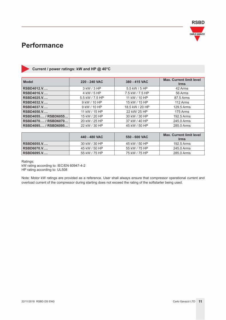
Performance
Current / power ratings: kW and HP @ 40°C
Model 220 - 240 VAC 380 - 415 VAC Max. Current limit levelIrms
RSBD4012.V…. 3 kW / 3 HP 5.5 kW / 5 HP 42 ArmsRSBD4016.V…. 4 kW / 5 HP 7.5 kW / 7.5 HP 56 ArmsRSBD4025.V…. 5.5 kW / 7.5 HP 11 kW / 10 HP 87.5 ArmsRSBD4032.V…. 9 kW / 10 HP 15 kW / 15 HP 112 ArmsRSBD4037.V…. 9 kW / 10 HP 18.5 kW / 20 HP 129.5 ArmsRSBD4050.V…. 11 kW / 15 HP 22 kW/ 25 HP 175 ArmsRSBD4055…. / RSBD6055… 15 kW / 20 HP 30 kW / 30 HP 192.5 ArmsRSBD4070…. / RSBD6070… 20 kW / 25 HP 37 kW / 40 HP 245.0 ArmsRSBD4095…. / RSBD6095… 22 kW / 30 HP 45 kW / 50 HP 285.0 Arms
440 - 480 VAC 550 - 600 VAC Max. Current limit levelIrms
RSBD6055.V…. 30 kW / 30 HP 45 kW / 50 HP 192.5 ArmsRSBD6070.V…. 45 kW / 50 HP 55 kW / 75 HP 245.0 ArmsRSBD6095.V…. 55 kW / 75 HP 75 kW / 75 HP 285.0 Arms
Ratings:kW rating according to: IEC/EN 60947-4-2HP rating according to: UL508
Note: Motor kW ratings are provided as a reference. User shall always ensure that compressor operational current and overload current of the compressor during starting does not exceed the rating of the softstarter being used.
RSBD DS ENG
12Carlo Gavazzi LTD
RSBD
RSGD 45_ 75mm DS ENG22/11/2018 12Carlo Gavazzi LTD
RSBD
22/11/2018
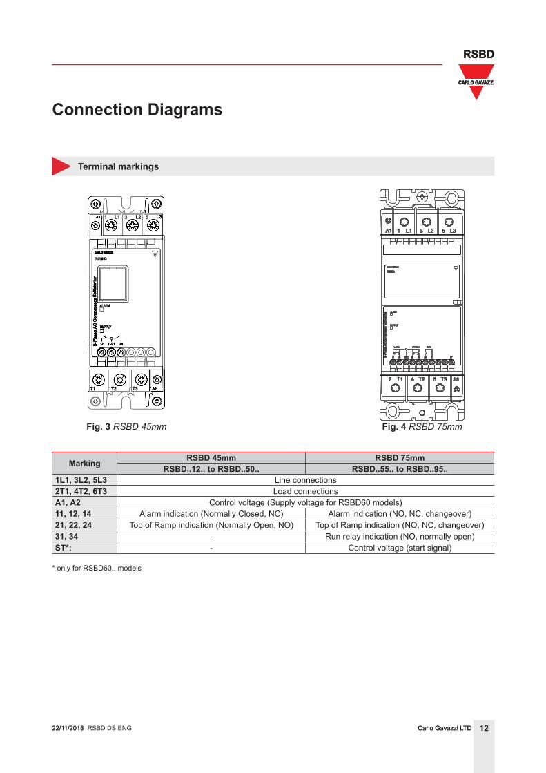
Connection Diagrams
Terminal markings
Fig. 3 RSBD 45mm Fig. 4 RSBD 75mm
Marking RSBD 45mm RSBD 75mmRSBD..12.. to RSBD..50.. RSBD..55.. to RSBD..95..
1L1, 3L2, 5L3 Line connections2T1, 4T2, 6T3 Load connectionsA1, A2 Control voltage (Supply voltage for RSBD60 models)11, 12, 14 Alarm indication (Normally Closed, NC) Alarm indication (NO, NC, changeover)21, 22, 24 Top of Ramp indication (Normally Open, NO) Top of Ramp indication (NO, NC, changeover)31, 34 - Run relay indication (NO, normally open)ST*: - Control voltage (start signal)
* only for RSBD60.. models
RSBD DS ENG
13Carlo Gavazzi LTD
RSBD
RSGD 45_ 75mm DS ENG22/11/2018 13Carlo Gavazzi LTD
RSBD
22/11/2018
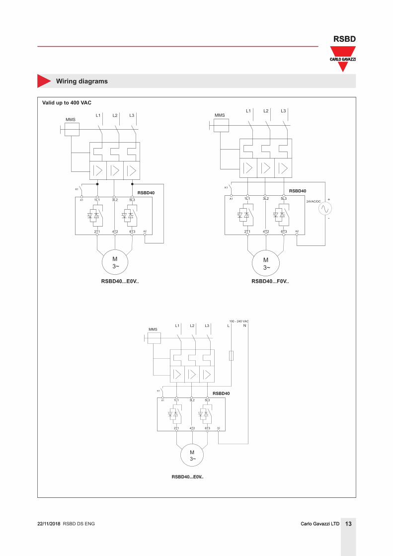
Wiring diagrams
Valid up to 400 VAC
RSBD40...E0V.. RSBD40...F0V..
RSBD40
+
-
RSBD40
RSBD40...E0V..
RSBD40
RSBD40...E0V.. RSBD40...F0V..
RSBD40...E0V.. RSBD40...F0V..
RSBD40
+
-
RSBD40
RSBD40...E0V..
RSBD40
RSBD DS ENG
14Carlo Gavazzi LTD
RSBD
RSGD 45_ 75mm DS ENG22/11/2018 14Carlo Gavazzi LTD
RSBD
22/11/2018
Wiring diagrams
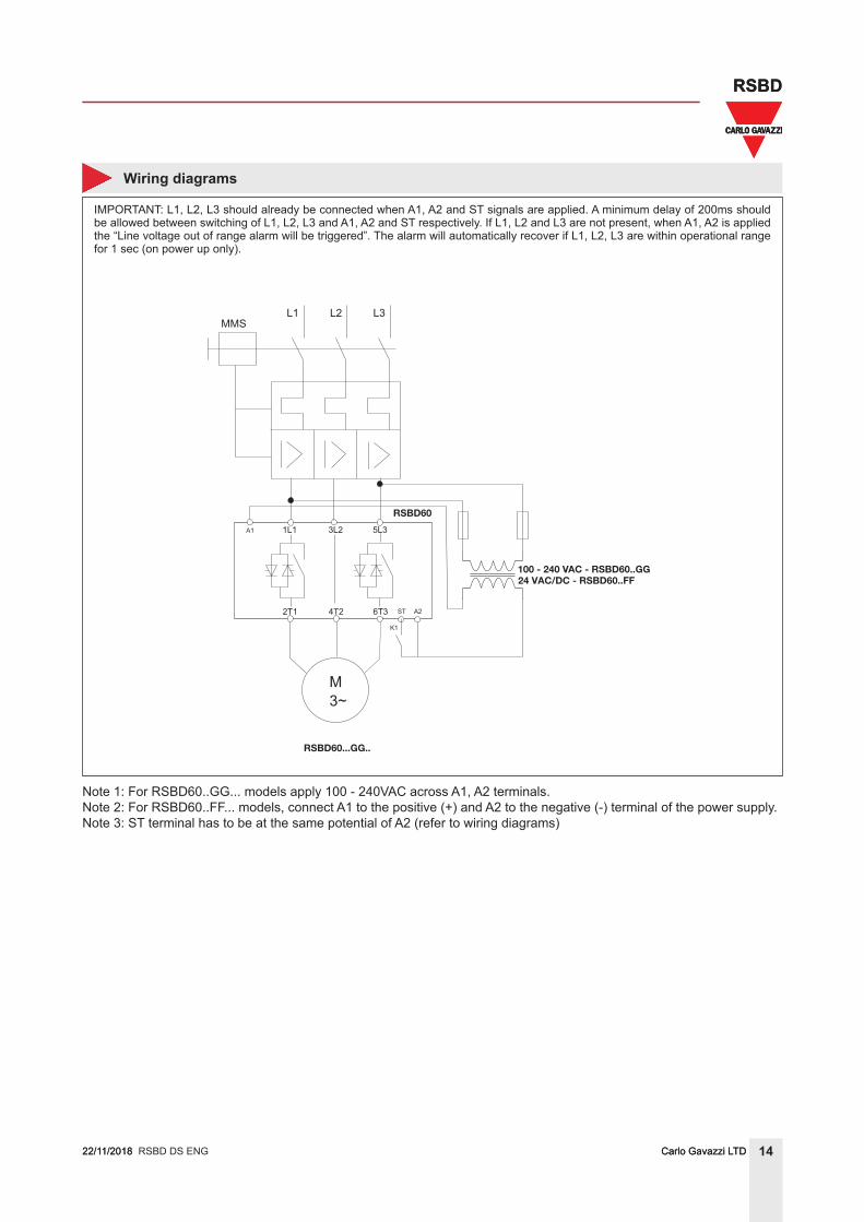
RSBD60...GG..
RSBD60
100 - 240 VAC - RSBD60..GG24 VAC/DC - RSBD60..FF
IMPORTANT: L1, L2, L3 should already be connected when A1, A2 and ST signals are applied. A minimum delay of 200ms should be allowed between switching of L1, L2, L3 and A1, A2 and ST respectively. If L1, L2 and L3 are not present, when A1, A2 is applied the “Line voltage out of range alarm will be triggered”. The alarm will automatically recover if L1, L2, L3 are within operational range for 1 sec (on power up only).
Note 1: For RSBD60..GG... models apply 100 - 240VAC across A1, A2 terminals.Note 2: For RSBD60..FF... models, connect A1 to the positive (+) and A2 to the negative (-) terminal of the power supply.Note 3: ST terminal has to be at the same potential of A2 (refer to wiring diagrams)
RSBD DS ENG
15Carlo Gavazzi LTD
RSBD
RSGD 45_ 75mm DS ENG22/11/2018 15Carlo Gavazzi LTD
RSBD
22/11/2018
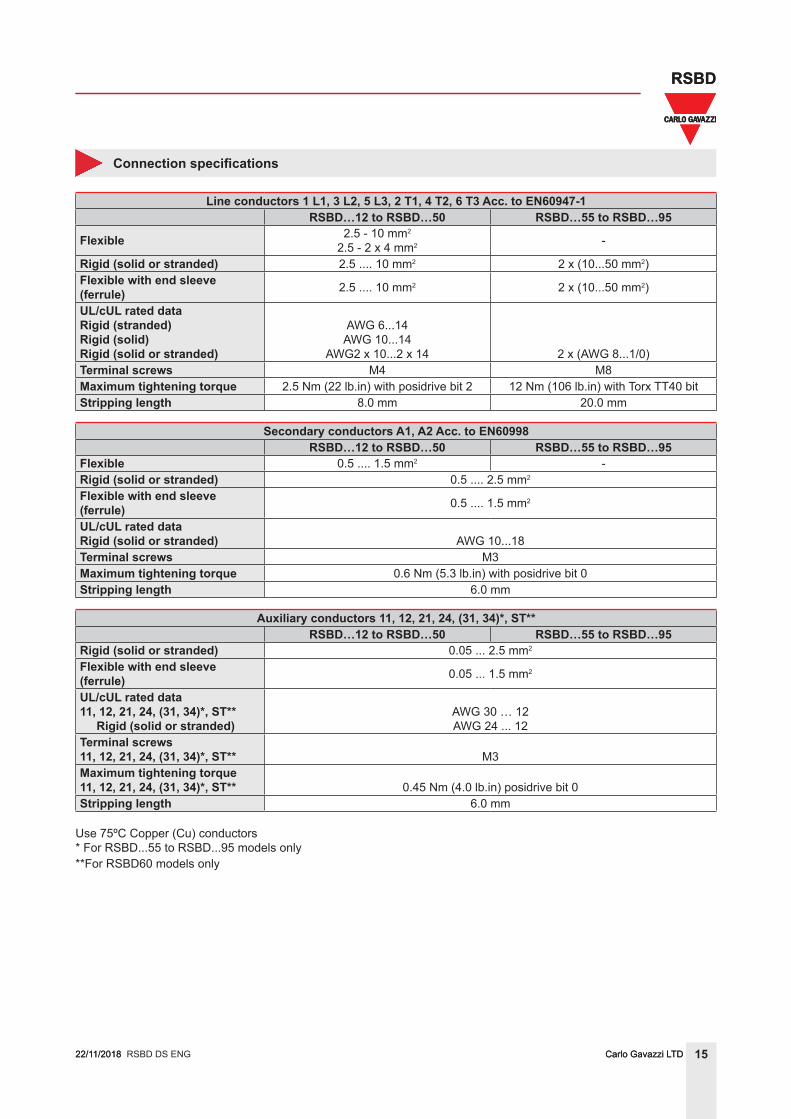
Connection specifications
Line conductors 1 L1, 3 L2, 5 L3, 2 T1, 4 T2, 6 T3 Acc. to EN60947-1RSBD…12 to RSBD…50 RSBD…55 to RSBD…95
Flexible 2.5 - 10 mm2
2.5 - 2 x 4 mm2 -
Rigid (solid or stranded) 2.5 .... 10 mm2 2 x (10...50 mm2)Flexible with end sleeve (ferrule) 2.5 .... 10 mm2 2 x (10...50 mm2)
UL/cUL rated dataRigid (stranded)Rigid (solid)Rigid (solid or stranded)
AWG 6...14AWG 10...14
AWG2 x 10...2 x 14 2 x (AWG 8...1/0)Terminal screws M4 M8Maximum tightening torque 2.5 Nm (22 lb.in) with posidrive bit 2 12 Nm (106 lb.in) with Torx TT40 bitStripping length 8.0 mm 20.0 mm
Secondary conductors A1, A2 Acc. to EN60998RSBD…12 to RSBD…50 RSBD…55 to RSBD…95
Flexible 0.5 .... 1.5 mm2 -Rigid (solid or stranded) 0.5 .... 2.5 mm2
Flexible with end sleeve (ferrule) 0.5 .... 1.5 mm2
UL/cUL rated dataRigid (solid or stranded) AWG 10...18Terminal screws M3Maximum tightening torque 0.6 Nm (5.3 lb.in) with posidrive bit 0Stripping length 6.0 mm
Auxiliary conductors 11, 12, 21, 24, (31, 34)*, ST**RSBD…12 to RSBD…50 RSBD…55 to RSBD…95
Rigid (solid or stranded) 0.05 ... 2.5 mm2
Flexible with end sleeve (ferrule) 0.05 ... 1.5 mm2
UL/cUL rated data11, 12, 21, 24, (31, 34)*, ST** Rigid (solid or stranded)
AWG 30 … 12AWG 24 ... 12
Terminal screws11, 12, 21, 24, (31, 34)*, ST** M3Maximum tightening torque11, 12, 21, 24, (31, 34)*, ST** 0.45 Nm (4.0 lb.in) posidrive bit 0Stripping length 6.0 mm
Use 75ºC Copper (Cu) conductors* For RSBD...55 to RSBD...95 models only**For RSBD60 models only
RSBD DS ENG
16Carlo Gavazzi LTD
RSBD
RSGD 45_ 75mm DS ENG22/11/2018 16Carlo Gavazzi LTD
RSBD
22/11/2018
Troubleshooting
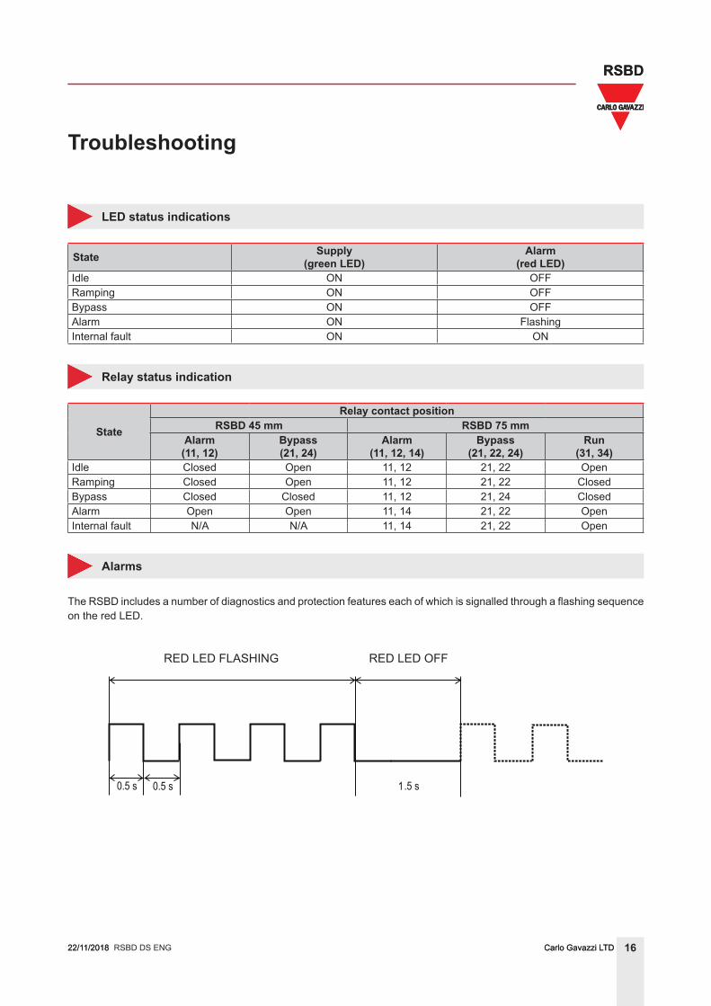
LED status indications
State Supply(green LED)
Alarm(red LED)
Idle ON OFFRamping ON OFFBypass ON OFFAlarm ON FlashingInternal fault ON ON
Relay status indication
State
Relay contact positionRSBD 45 mm RSBD 75 mm
Alarm(11, 12)
Bypass(21, 24)
Alarm(11, 12, 14)
Bypass(21, 22, 24)
Run(31, 34)
Idle Closed Open 11, 12 21, 22 OpenRamping Closed Open 11, 12 21, 22 ClosedBypass Closed Closed 11, 12 21, 24 ClosedAlarm Open Open 11, 14 21, 22 OpenInternal fault N/A N/A 11, 14 21, 22 Open
Alarms
The RSBD includes a number of diagnostics and protection features each of which is signalled through a flashing sequence on the red LED.
RED LED FLASHING RED LED OFF
RSBD DS ENG
17Carlo Gavazzi LTD
RSBD
RSGD 45_ 75mm DS ENG22/11/2018 17Carlo Gavazzi LTD
RSBD
22/11/2018
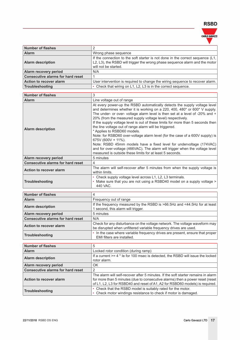
Number of flashes 2Alarm Wrong phase sequence
Alarm descriptionIf the connection to the soft starter is not done in the correct sequence (L1, L2, L3), the RSBD will trigger the wrong phase sequence alarm and the motor will not be started.
Alarm recovery period N/AConsecutive alarms for hard reset 1Action to recover alarm User intervention is required to change the wiring sequence to recover alarm.Troubleshooting • Check that wiring on L1, L2, L3 is in the correct sequence.
Number of flashes 3Alarm Line voltage out of range
Alarm description
At every power-up the RSBD automatically detects the supply voltage level and determines whether it is working on a 220, 400, 480* or 600* V supply. The under- or over- voltage alarm level is then set at a level of -20% and + 20% (from the measured supply voltage level) respectively.If the supply voltage level is out of these limits for more than 5 seconds then the line voltage out of range alarm will be triggered.* Applies to RSBD60 models.Note: for RSBD60 over-voltage alarm level (for the case of a 600V supply) is 675V (600V + 11%).Note: RSBD 45mm models have a fixed level for undervoltage (174VAC) and for over-voltage (466VAC). The alarm will trigger when the voltage level measured is outside these limits for at least 5 seconds.
Alarm recovery period 5 minutesConsecutive alarms for hard reset 4
Action to recover alarm The alarm will self-recover after 5 minutes from when the supply voltage is within limits.
Troubleshooting• Check supply voltage level across L1, L2, L3 terminals.• Make sure that you are not using a RSBD40 model on a supply voltage >
440 VAC.
Number of flashes 4Alarm Frequency out of range
Alarm description If the frequency measured by the RSBD is >66.5Hz and <44.5Hz for at least 1 second, this alarm will trigger.
Alarm recovery period 5 minutesConsecutive alarms for hard reset N/A
Action to recover alarm Check for any disturbance on the voltage network. The voltage waveform may be disrupted when unfiltered variable frequency drives are used.
Troubleshooting • In the case where variable frequency drives are present, ensure that proper EMI filters are installed.
Number of flashes 5Alarm Locked rotor condition (during ramp)
Alarm description If a current >= 4 * Ie for 100 msec is detected, the RSBD will issue the locked rotor alarm.
Alarm recovery period OKConsecutive alarms for hard reset 2
Action to recover alarmThe alarm will self-recover after 5 minutes. If the soft starter remains in alarm for more than 5 minutes (due to consecutive alarms) then a power reset (reset of L1, L2, L3 for RSBD40 and reset of A1, A2 for RSBD60 models) is required.
Troubleshooting • Check that the RSBD model is suitably rated for the motor.• Check motor windings resistance to check if motor is damaged.
RSBD DS ENG
18Carlo Gavazzi LTD
RSBD
RSGD 45_ 75mm DS ENG22/11/2018 18Carlo Gavazzi LTD
RSBD
22/11/2018
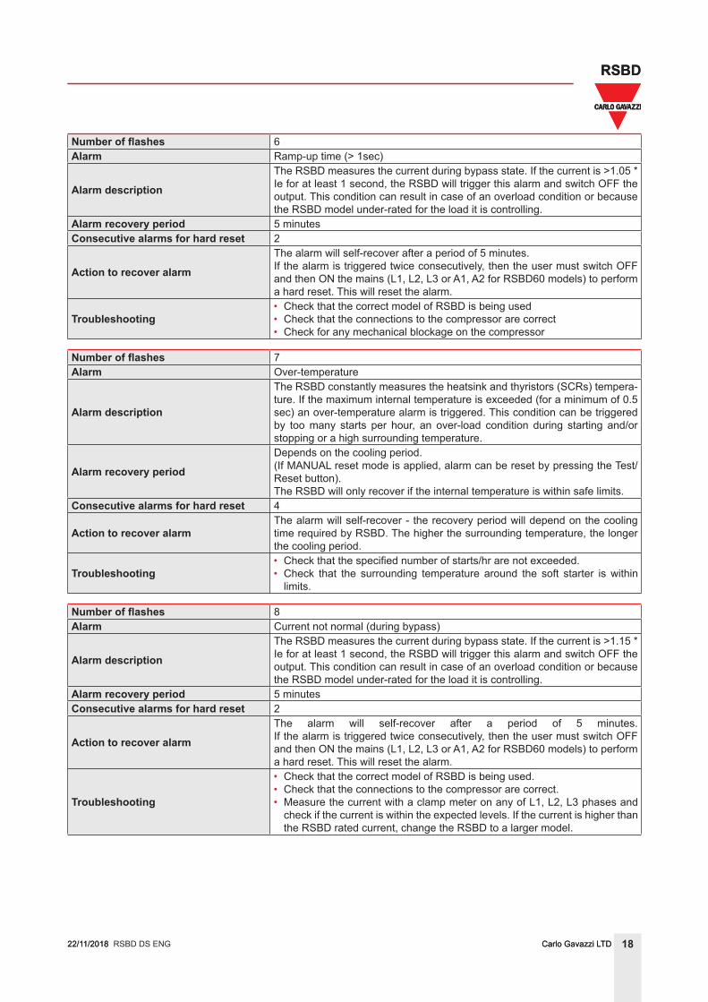
Number of flashes 6Alarm Ramp-up time (> 1sec)
Alarm description
The RSBD measures the current during bypass state. If the current is >1.05 * Ie for at least 1 second, the RSBD will trigger this alarm and switch OFF the output. This condition can result in case of an overload condition or because the RSBD model under-rated for the load it is controlling.
Alarm recovery period 5 minutesConsecutive alarms for hard reset 2
Action to recover alarm
The alarm will self-recover after a period of 5 minutes.If the alarm is triggered twice consecutively, then the user must switch OFF and then ON the mains (L1, L2, L3 or A1, A2 for RSBD60 models) to perform a hard reset. This will reset the alarm.
Troubleshooting• Check that the correct model of RSBD is being used• Check that the connections to the compressor are correct • Check for any mechanical blockage on the compressor
Number of flashes 7Alarm Over-temperature
Alarm description
The RSBD constantly measures the heatsink and thyristors (SCRs) tempera-ture. If the maximum internal temperature is exceeded (for a minimum of 0.5 sec) an over-temperature alarm is triggered. This condition can be triggered by too many starts per hour, an over-load condition during starting and/or stopping or a high surrounding temperature.
Alarm recovery period
Depends on the cooling period.(If MANUAL reset mode is applied, alarm can be reset by pressing the Test/Reset button).The RSBD will only recover if the internal temperature is within safe limits.
Consecutive alarms for hard reset 4
Action to recover alarmThe alarm will self-recover - the recovery period will depend on the cooling time required by RSBD. The higher the surrounding temperature, the longer the cooling period.
Troubleshooting• Check that the specified number of starts/hr are not exceeded.• Check that the surrounding temperature around the soft starter is within
limits.
Number of flashes 8Alarm Current not normal (during bypass)
Alarm description
The RSBD measures the current during bypass state. If the current is >1.15 * Ie for at least 1 second, the RSBD will trigger this alarm and switch OFF the output. This condition can result in case of an overload condition or because the RSBD model under-rated for the load it is controlling.
Alarm recovery period 5 minutesConsecutive alarms for hard reset 2
Action to recover alarm
The alarm will self-recover after a period of 5 minutes. If the alarm is triggered twice consecutively, then the user must switch OFF and then ON the mains (L1, L2, L3 or A1, A2 for RSBD60 models) to perform a hard reset. This will reset the alarm.
Troubleshooting
• Check that the correct model of RSBD is being used.• Check that the connections to the compressor are correct. • Measure the current with a clamp meter on any of L1, L2, L3 phases and
check if the current is within the expected levels. If the current is higher than the RSBD rated current, change the RSBD to a larger model.
RSBD DS ENG
19Carlo Gavazzi LTD
RSBD
22/11/2018
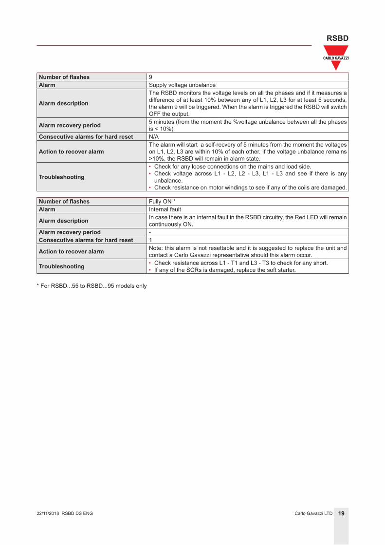
Number of flashes 9Alarm Supply voltage unbalance
Alarm description
The RSBD monitors the voltage levels on all the phases and if it measures a difference of at least 10% between any of L1, L2, L3 for at least 5 seconds, the alarm 9 will be triggered. When the alarm is triggered the RSBD will switch OFF the output.
Alarm recovery period 5 minutes (from the moment the %voltage unbalance between all the phases is < 10%)
Consecutive alarms for hard reset N/A
Action to recover alarmThe alarm will start a self-recvery of 5 minutes from the moment the voltages on L1, L2, L3 are within 10% of each other. If the voltage unbalance remains >10%, the RSBD will remain in alarm state.
Troubleshooting
• Check for any loose connections on the mains and load side. • Check voltage across L1 - L2, L2 - L3, L1 - L3 and see if there is any
unbalance.• Check resistance on motor windings to see if any of the coils are damaged.
Number of flashes Fully ON *Alarm Internal fault
Alarm description In case there is an internal fault in the RSBD circuitry, the Red LED will remain continuously ON.
Alarm recovery period -Consecutive alarms for hard reset 1
Action to recover alarm Note: this alarm is not resettable and it is suggested to replace the unit and contact a Carlo Gavazzi representative should this alarm occur.
Troubleshooting • Check resistance across L1 - T1 and L3 - T3 to check for any short.• If any of the SCRs is damaged, replace the soft starter.
* For RSBD...55 to RSBD...95 models only
RSBD DS ENG
20Carlo Gavazzi LTD
RSBD
RSGD 45_ 75mm DS ENG22/11/2018
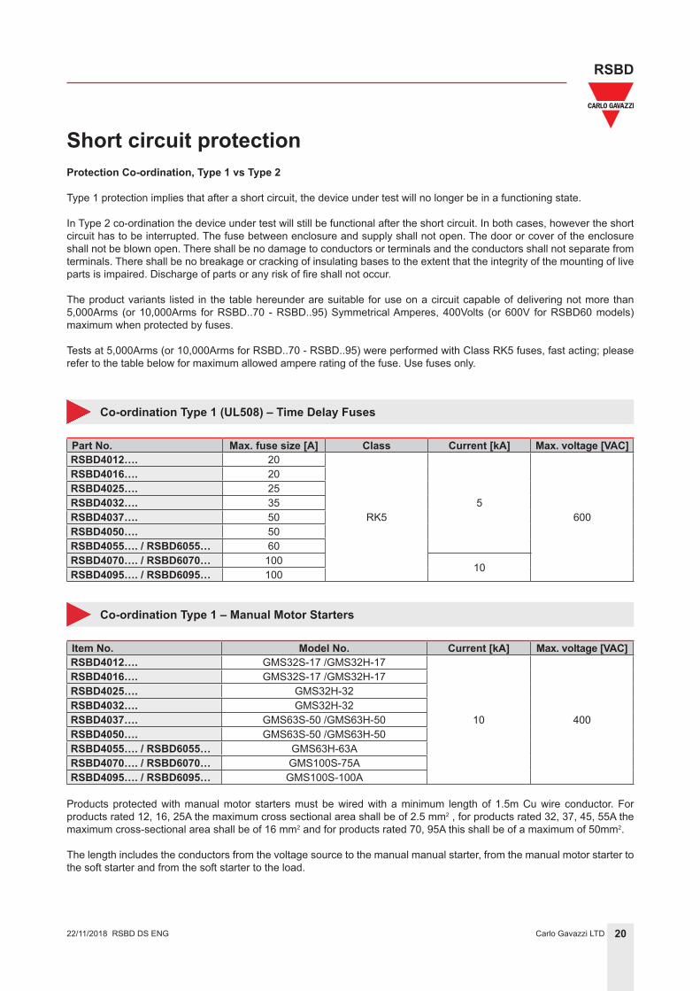
Short circuit protection
Co-ordination Type 1 (UL508) – Time Delay Fuses
Part No. Max. fuse size [A] Class Current [kA] Max. voltage [VAC]RSBD4012…. 20
RK55
600
RSBD4016…. 20RSBD4025…. 25RSBD4032…. 35RSBD4037…. 50RSBD4050…. 50RSBD4055…. / RSBD6055… 60RSBD4070…. / RSBD6070… 100 10RSBD4095…. / RSBD6095… 100
Co-ordination Type 1 – Manual Motor Starters
Item No. Model No. Current [kA] Max. voltage [VAC]RSBD4012…. GMS32S-17 /GMS32H-17
10 400
RSBD4016…. GMS32S-17 /GMS32H-17RSBD4025…. GMS32H-32RSBD4032…. GMS32H-32RSBD4037…. GMS63S-50 /GMS63H-50RSBD4050…. GMS63S-50 /GMS63H-50RSBD4055…. / RSBD6055… GMS63H-63ARSBD4070…. / RSBD6070… GMS100S-75ARSBD4095…. / RSBD6095… GMS100S-100A
Products protected with manual motor starters must be wired with a minimum length of 1.5m Cu wire conductor. For products rated 12, 16, 25A the maximum cross sectional area shall be of 2.5 mm2 , for products rated 32, 37, 45, 55A the maximum cross-sectional area shall be of 16 mm2 and for products rated 70, 95A this shall be of a maximum of 50mm2.
The length includes the conductors from the voltage source to the manual manual starter, from the manual motor starter to the soft starter and from the soft starter to the load.
Protection Co-ordination, Type 1 vs Type 2
Type 1 protection implies that after a short circuit, the device under test will no longer be in a functioning state.
In Type 2 co-ordination the device under test will still be functional after the short circuit. In both cases, however the short circuit has to be interrupted. The fuse between enclosure and supply shall not open. The door or cover of the enclosure shall not be blown open. There shall be no damage to conductors or terminals and the conductors shall not separate from terminals. There shall be no breakage or cracking of insulating bases to the extent that the integrity of the mounting of live parts is impaired. Discharge of parts or any risk of fire shall not occur.
The product variants listed in the table hereunder are suitable for use on a circuit capable of delivering not more than 5,000Arms (or 10,000Arms for RSBD..70 - RSBD..95) Symmetrical Amperes, 400Volts (or 600V for RSBD60 models) maximum when protected by fuses.
Tests at 5,000Arms (or 10,000Arms for RSBD..70 - RSBD..95) were performed with Class RK5 fuses, fast acting; please refer to the table below for maximum allowed ampere rating of the fuse. Use fuses only.
RSBD DS ENG
21Carlo Gavazzi LTD
RSBD
22/11/2018
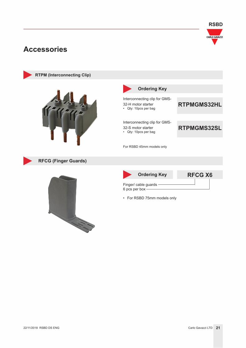
Accessories
RTPM (Interconnecting Clip)
Interconnecting clip for GMS-32-H motor starter• Qty: 10pcs per bag
Ordering Key
RTPMGMS32HL
Interconnecting clip for GMS-32-S motor starter• Qty: 10pcs per bag
RTPMGMS32SL
RFCG (Finger Guards)
Finger/ cable guards6 pcs per box
• For RSBD 75mm models only
RFCG X6 Ordering Key
RSBD DS ENG
For RSBD 45mm models only
22Carlo Gavazzi LTD
RSBD
RSGD 45_ 75mm DS ENG22/11/2018
Accessories
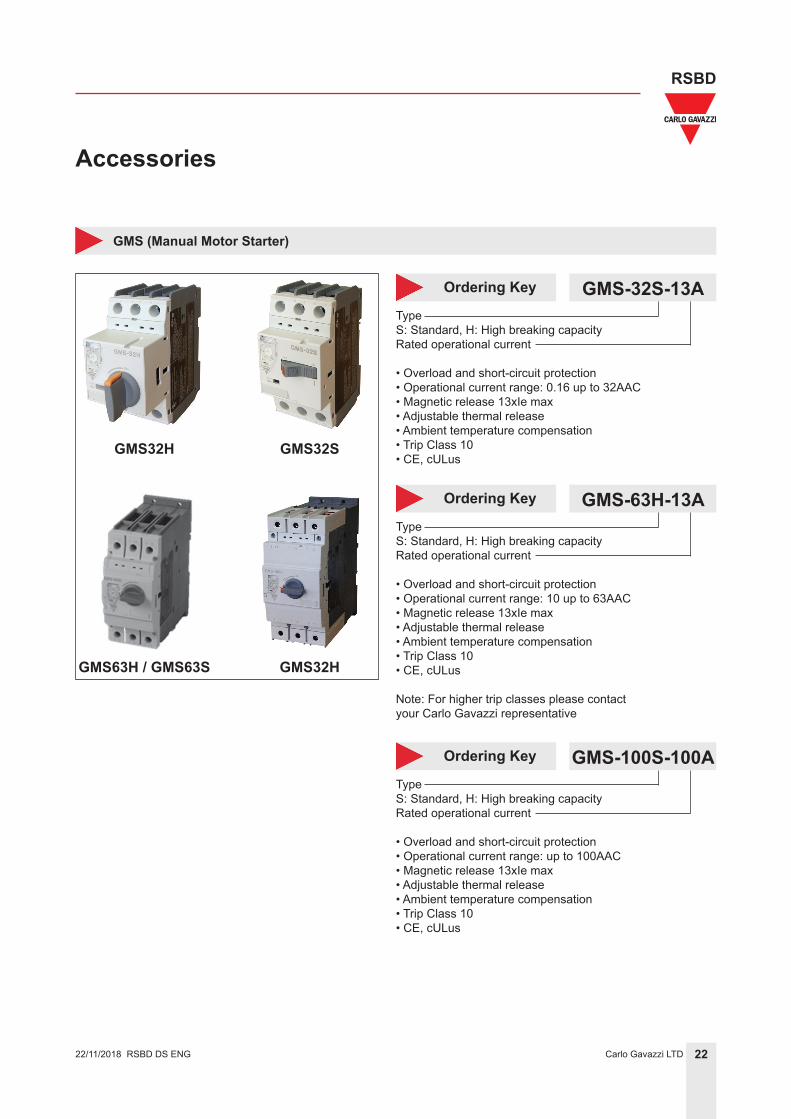
GMS (Manual Motor Starter)
TypeS: Standard, H: High breaking capacityRated operational current
• Overload and short-circuit protection• Operational current range: 0.16 up to 32AAC• Magnetic release 13xIe max• Adjustable thermal release• Ambient temperature compensation• Trip Class 10• CE, cULus
GMS-32S-13A Ordering Key
TypeS: Standard, H: High breaking capacityRated operational current
• Overload and short-circuit protection• Operational current range: 10 up to 63AAC• Magnetic release 13xIe max• Adjustable thermal release• Ambient temperature compensation• Trip Class 10• CE, cULus
Note: For higher trip classes please contact your Carlo Gavazzi representative
GMS-63H-13A Ordering Key
TypeS: Standard, H: High breaking capacityRated operational current
• Overload and short-circuit protection• Operational current range: up to 100AAC• Magnetic release 13xIe max• Adjustable thermal release• Ambient temperature compensation• Trip Class 10• CE, cULus
GMS-100S-100A Ordering Key
GMS32H GMS32S
GMS63H / GMS63S GMS32H
RSBD DS ENG
23Carlo Gavazzi LTD
RSBD
RSGD 45_ 75mm DS ENG22/11/2018
Accessories
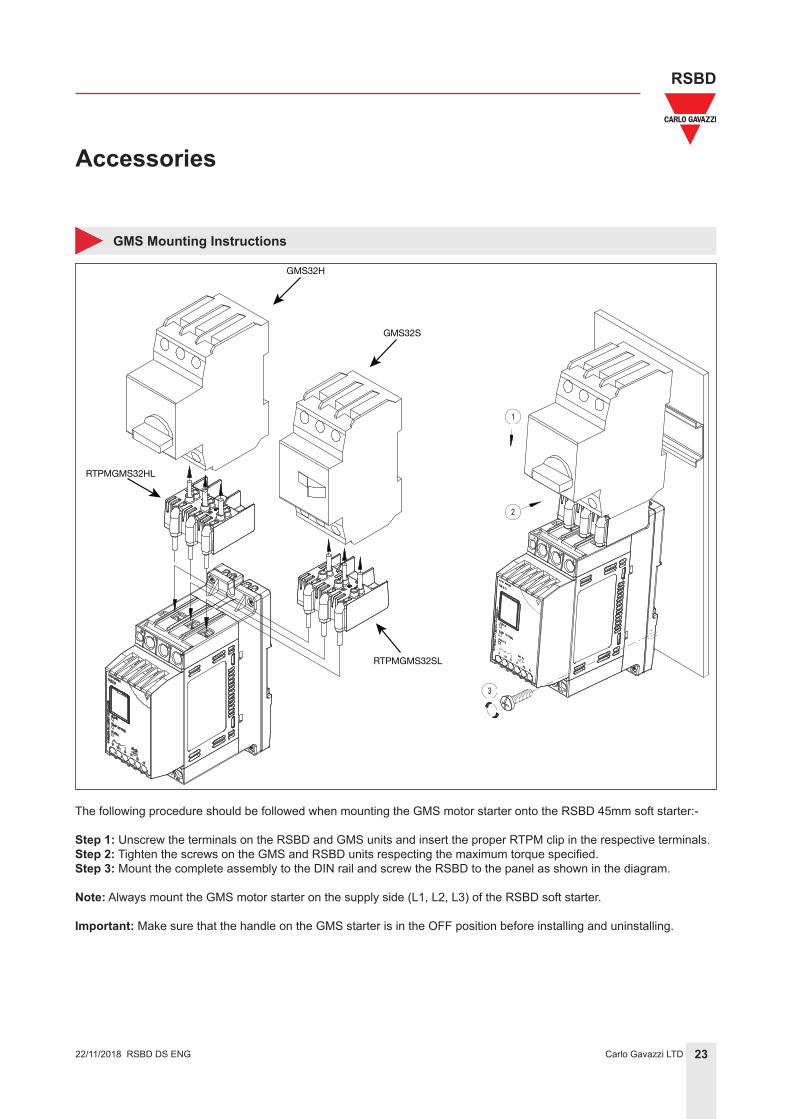
GMS Mounting Instructions
GMS32H
GMS32S
RTPMGMS32HL
RTPMGMS32SL
The following procedure should be followed when mounting the GMS motor starter onto the RSBD 45mm soft starter:-
Step 1: Unscrew the terminals on the RSBD and GMS units and insert the proper RTPM clip in the respective terminals.Step 2: Tighten the screws on the GMS and RSBD units respecting the maximum torque specified.Step 3: Mount the complete assembly to the DIN rail and screw the RSBD to the panel as shown in the diagram.
Note: Always mount the GMS motor starter on the supply side (L1, L2, L3) of the RSBD soft starter.
Important: Make sure that the handle on the GMS starter is in the OFF position before installing and uninstalling.
RSBD DS ENG