Embed Size (px)
Citation preview

Bending of a Cosserat Elastic Bar of Square Cross
Section - Theory and Experiment
Roderic Lakes, W. J. Drugan ∗†
Department of Engineering Physics, Engineering Mechanics Program,Department of Materials Science, Rheology Research Center,
University of Wisconsin, 1500 Engineering Drive, Madison, WI 53706-1687Preprint Journal of Applied Mechanics, 82(9), 091002 (Sep 01, 2015) (8 pages)
June 30, 2015
Abstract
Pure bending experiments on prismatic bars of square cross-section composed of reticulatedpolymer foam exhibit deformation behavior not captured by classical elasticity theory. Perhapsthe clearest example of this is the observed sigmoidal deformation of the bars’ lateral surfaces,which are predicted by classical elasticity theory to tilt but remain planar upon pure momentapplication. Such foams have a non-negligible length scale compared to the bars’ cross-sectiondimensions, whereas classical elasticity theory contains no inherent length scale. All thesefacts raise the intriguing question: is there a richer, physically-sensible, yet still continuumand relatively simple elasticity theory capable of modeling the observed phenomenon in thesematerials? This paper reports our exploration of the hypothesis that Cosserat elasticity can. Weemploy the principle of minimum potential energy for homogeneous isotropic Cosserat elasticmaterial in which the microrotation vector is taken to be independent of the macrorotationvector (as prior experiments indicate it should be in general to model such materials) to obtain anapproximate three-dimensional solution to pure bending of a prismatic bar having a square cross-section. We show that this solution, and hence Cosserat elasticity, captures the experimentally-observed nonclassical deformation feature, both qualitatively and quantitatively, for reasonablevalues of the Cosserat moduli. A further interesting conclusion is that a single experiment – thepure bending one – suffices to reveal directly, via the observation of surface deformation, thepresence of nonclassical elastic effects describable by Cosserat elasticity.
∗[email protected]†[email protected]
1
1 Introduction
For many purposes it is expedient to make use of continuum representations of materials, all ofwhich actually have microstructure. Several such continuum theories with different amounts offreedom are available. An early theory of Navier called uniconstant was proposed based on atomicinteraction theory. It had too little freedom and was abandoned since it predicted a Poisson’s ratioof 1/4 for all materials. The elasticity theory currently accepted as classical allows Poisson’s ratiosin isotropic materials in the range −1 to 1/2. Translations of points are allowed but not pointrotations. Classical elasticity has no length scale. By contrast, Cosserat elasticity allows rotationsof points and has a length scale, so it is pertinent to the deformation of heterogeneous materialswhose heterogeneity size scale is not negligible compared to dimensions of a structural componentor the sizes of e.g. holes or cracks, or the length scale of the phenomenon under investigation, suchas wavelength in a wave propagation problem. Too, the toughness of materials has a length scale;the value of this length cannot be extracted from the classical elastic properties of the material. Thetoughness of foams is calculated by considering a crack in the foam under tension, and analyzingthe bending of the cell ribs [1]; the toughness depends on the cell size in the foam.
The constitutive equations for an isotropic Cosserat [2] or micropolar [3] elastic solid are
σij = 2Gεij + λεkkδij + κeijk(rk − φk) (1)
mij = αφk,kδij + βφi,j + γφj,i (2)
in which σij is the force stress tensor (symmetric in classical elasticity but asymmetric here), mij
is the couple stress tensor (moment per unit area, asymmetric in general), εij = (ui,j + uj,i)/2is the small strain tensor, ui the displacement vector, and eijk is the permutation symbol. Themicrorotation vector φi in Cosserat elasticity is kinematically distinct from the macrorotation vectorri = (eijkuk,j)/2. φi refers to the rotation of points themselves, while ri refers to the rotationassociated with movement of nearby points. The usual Einstein summation convention for repeatedindices is employed, and a comma denotes differentiation with respect to ensuing subscripts whichrepresent spatial Cartesian coordinates.
Some authors, e.g. [4], object to the notion of an independent microrotation vector. If oneassumes, following Koiter [5] (who did so for simplicity), that the macrorotation and microrota-tion vectors are equal, then in Cosserat elasticity, N = 1, or equivalently κ → ∞ [see Eq. (8)].Careful size effect experiments, however, give measured N values that are significantly smaller thanunity [6, 7]. Furthermore, the notion of independent microrotation is confirmed theoretically inhomogenization analyses for various lattices and composites; see e.g. [8] and several references citedtherein. Although prior experiments exclude N = 1 for foams and bone, they do not necessarilyexclude the presence of additional freedom such as that incorporated in micromorphic / Mindlinmicrostructure theory.
As Eqns. (1, 2) show, six independent elastic constants are required to describe general three-dimensional deformations of an isotropic Cosserat elastic solid: α, β, γ, κ, λ, and G. (Eringen [3]uses 2µ+ κ = 2G, so µ differs from the shear modulus G in his notation.) Classical elasticity is aspecial case, achieved by allowing α, β, γ, κ to become zero. The classical Lame elastic constants
JAM Lakes and Drugan 2

λ and G then remain, and there is no couple stress. Technical constants are as follows:
Y oung′s modulus E =(2G)(3λ+ 2G)
2λ+ 2G(3)
Shear modulus G (4)
Poisson′s ratio ν =λ
2(λ+G)(5)
Characteristic length, torsion `t =
√β + γ
2G(6)
Characteristic length, bending `b =
√γ
4G(7)
Coupling number N =
√κ
2G+ κ(8)
Polar ratio Ψ =β + γ
α+ β + γ. (9)
Continuum theories make no reference to structural features; however, they are intended torepresent physical solids which always have some form of microstructure. The couple stresses inCosserat and microstructure elasticity represent spatial averages of distributed moments per unitarea, just as the ordinary (force) stress represents a spatial average of force per unit area. Whilesuch moments can occur on the atomic scale or the nano scale, moments may be also transmittedon a much larger scale, through fibers in fiber-reinforced materials or in the cell ribs or walls incellular solids. The Cosserat characteristic lengths will then be associated with the physical sizescales in the microstructure, and be sufficiently large to observe experimentally on the micro-scaleor the milli-scale.
Structures of sufficient regularity can be subject to homogenization analysis to extract the elasticconstants, including Cosserat constants. In lattice type cellular solids the characteristic length maybe comparable to the average cell size [9]. Bigoni and Drugan [10] derived homogeneous Cosseratmaterial moduli that best represent heterogeneous Cauchy material behavior under general loading.They applied this to two specific matrix-inclusion composite microstructures: one with cylindricalinclusions (2D plane strain), and one with spherical inclusions (3D). They showed the Cosseratcharacteristic length can be determined analytically when inclusions are less stiff than the matrix,but when these are equal to or stiffer than the matrix, Cosserat effects were shown to be excluded.
Cosserat elastic effects have been observed experimentally. For example, size effects are ob-served to occur in torsion and bending of foams [6, 7] and of compact bone. Size effect in boneexceeds a factor of three in effective shear modulus [11]. Classical elasticity predicts effective shearmodulus independent of specimen size. Experiments show the apparent modulus increases substan-tially as the specimen diameter becomes smaller. The Cosserat continuum concept accounts forthese observations. From a micro-structural perspective, a contribution to the twisting or bendingmoment arises from twist or bend of each individual fiber in fibrous materials or each rib in cellularsolids, hence size effects. Heterogeneous structure does not necessarily give rise to size effects: nosize effects were observed in particulate composites with large particles [12] nor in syntactic foamsthat contain small particles [6], and as mentioned Bigoni and Drugan [10] showed theoretically thatno Cosserat effects occur for inclusions stiffer than the matrix (for cylindrical inclusions in planestrain, and for spherical inclusions in 3D). The Cosserat characteristic length was determined in apolymer honeycomb as a two dimensional system [13]. On smaller scales, asymmetric interatomicaction was studied in magnetic media; the existence of non-central load was demonstrated with
JAM Lakes and Drugan 3
electron paramagnetic resonance [14].Experiments are interpreted with the aid of analytical solutions for the configuration under
study. For example, analytical solutions are known for torsion [12] and bending [15] of an isotropicCosserat linear elastic circular cylinder. These analyses disclose size effects in structural rigidityin which slender rods are stiffer than predicted by classical elasticity using moduli obtained in theabsence of gradients.
Changes in the surface deformation field are of particular interest in experiments. For example,a bar of rectangular cross section in torsion exhibits warp, an in-plane deformation parallel to thesurface. The classical warp is predicted to be reduced in a Cosserat elastic solid [16]; this gives riseto an observed redistribution of strain away from regions that are classically highly strained [17][18] into classically low strain regions. This ameliorates concentration of strain. The reduction ofwarp has been observed via holography [19].
Bending of Cosserat elastic bars of non-circular cross section is of interest in the context ofchange in deformation field. Saint Venant’s problem has been considered in an abstract sensethat shows existence of solution [20]; bending has been considered in terms of functions to bedetermined [21]. A plane stress approximation for κ→∞ was presented, showing changes in stressfields [22], hence size effects. Plate bending also discloses size effects in the rigidity [12]. Severalbeam theory analyses have been presented [23]; cross section shape change was not considered.A three dimensional analysis was presented [24] in which constraints on the lateral deformationwere imposed. In summary, none of the available studies of bending deals with deformations of aprismatic bar of square cross section subjected to pure bending.
Previous experiments on two foam types have provided the following values for the isotropic clas-sical and Cosserat elastic moduli (via the technical constants of Eqs. (3-9)): For dense polyurethanefoam [6], E = 300 MPa, G = 104 MPa, ν = 0.4, `t = 0.62 mm, `b = 0.33 mm, N2 = 0.04, Ψ =1.5. This is a closed cell foam of density 340 kg/m3; the cell size is 0.05 to 0.15 mm.
For polymethacrylamide closed cell foam type Rohacell WF300 [7], E = 637 MPa, G = 285MPa, `t = 0.8 mm, `b = 0.77 mm, N2 ≈ 0.04, Ψ = 1.5. This is a closed cell foam of density 380kg/m3; the cell size is 0.65 mm. Inference of Poisson’s ratio from Young’s and shear modulus givesν = 0.12; the low value is likely due to slight anisotropy in the foam. Other polymethacrylamidefoams studied in this series had density 110 kg/m3 and 60 kg/m3; characteristic lengths weresomewhat smaller; N was not accurately determined owing to the difficulty in cutting sufficientlyslender specimens.
Thus, in these previously-tested foams, `b ranged between approximately 1.2 to 6.6 times thecell size. As noted, these were closed-cell foams, in contrast to the open-cell foams tested in thepresent work.
The present research explores bending of a bar of square cross section in which Cosserat effectsgive rise to out of plane effects normal to the surface. Such effects are particularly amenable toexperiment.
2 Experiment
2.1 Materials and methods
Bars of open cell reticulated polyurethane foam (Scott Industrial foam [25]) were used. They were50 mm in square cross section and about 300 mm long. One foam had average cell size 1.2 mm or20 pores per inch (Figure 1); the other foam had average cell size 0.4 mm (Figure 2). The mass anddimensions of each bar were measured. Flat stalks about 30 cm long were cemented to each end.Displacement of the surface was measured via digital photography. Shadow Moire was attempted
JAM Lakes and Drugan 4
Figure 1: Open cell polyurethane foam. Scale bar, 5 mm.
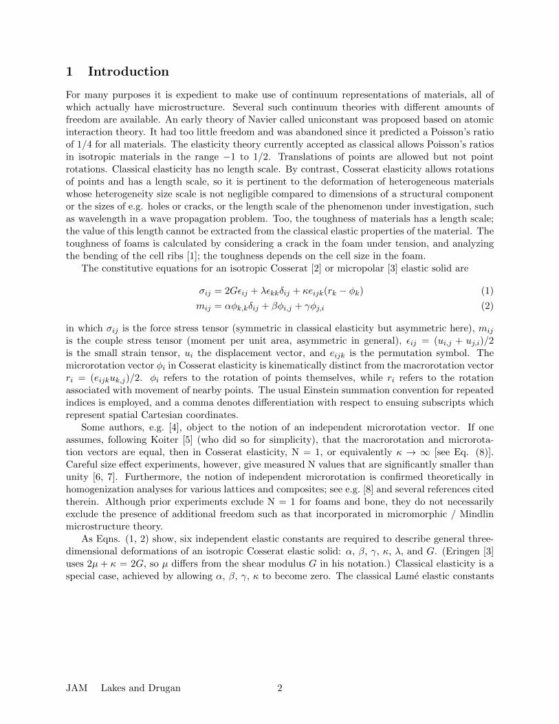
Figure 2: Portion of the bent 50 mm wide test beam of 0.4 mm cell size foam viewed at an obliqueangle.
but surface roughness and light penetration precluded useful fringes. The foam bar was placed onan optical table and a digital camera was mounted at an oblique angle above it. Fiducial crosssection lines were drawn on the foam with ink or acrylic paint. Pure bending was achieved bybringing the ends of the stalks into contact. The stalk length defined the radius of curvature R =27.5 cm from the neutral axis. Sigmoid bulge was sufficient to be discerned by the unaided eye.The maximum strain was 4.5%, within the linear range for this class of foam. Digital photographswere taken before and after bending. A thin straight line was drawn digitally on each image fromcorresponding points at the edges. These points were used as reference points corresponding tozero motion; this procedure eliminates the effect of classical tilt. Displacements were measured onthe images via GIMP image processing software. No averaging or smoothing was done. Pixel countwas converted to displacement using the known width of the bar; the scale factor was about 30pixels per millimeter. Because the end points correspond to zero motion, the tilt deformation ofthe lateral surfaces is subtracted out. Several such experiments were done. Curve fits of sinusoidalform serve as guides to the eye. Tilt deformation was evaluated via photographs taken from an
JAM Lakes and Drugan 5

orthogonal direction.Tests were also done to probe anisotropy. Cubes of foam were cut and compressed to less than
5% strain in a servo-hydraulic frame. Compression was done in each of three orthogonal directionsto determine moduli.
2.2 Results
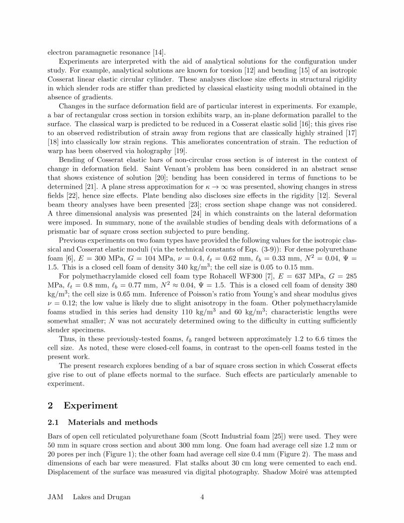
Results are shown in Figure 3. The lateral surface exhibits a sigmoid bulge deformation in whichthe magnitude is larger for the larger cell foam. Scatter in the points arises from heterogeneity inthe deformation of the foam cells. The density of each foam was ρ = 0.030 g/cm3 or 30 kg/m3. Tiltdeformation is not shown in the graphs because the image processing method defines the motionat the edges (i.e., corners) to be zero. Scatter of the points is attributed largely to the non-affinedeformation known to occur in foams. Pixel resolution also contributes to the scatter for the smallercell foam.
The foam with 1.2 mm cells had a ratio of moduli in different directions of 1.6, indicatingsubstantial anisotropy; the foam with 0.4 mm cells was isotropic to within 10%.
Figure 3: Deformation uy vs. position, excluding tilt; left, larger cell foam, cell size 1.2 mm; right,cell size 0.4 mm. Comparison of the two figures shows the sigmoidal displacement is increased forlarger pore size, implying a local length scale effect that suggests modeling via Cosserat theory.
3 Bending analysis
3.1 Three-dimensional governing equations for a Cosserat medium
The complete governing equations for three-dimensional infinitesimal deformations of a homoge-neous, isotropic linear elastic Cosserat medium in equilibrium with no body forces are the con-stitutive equations (1) and (2), the strain-displacement and macrorotation-displacement equationsnoted earlier, namely
εij = (ui,j + uj,i)/2 (10)
ri = (eijkuk,j)/2, (11)
JAM Lakes and Drugan 6
and the equations of force and moment equilibrium, respectively
σij,i = 0 (12)
mij,i + ejklσkl = 0. (13)
For all boundary portions on which displacements are not prescribed, the force traction vector tiand the moment traction vector mi must be prescribed; these are related through the boundary’soutward unit normal vector ni to the force and couple stress tensors as
ti = σjinj , mi = mjinj . (14)
3.2 Classical three-dimensional pure bending solution
The classical three-dimensional displacement field solution for pure bending of prismatic bars inhomogeneous, isotropic linear elasticity is
ux = −z2 + ν(x2 − y2)
2R, uy = −ν xy
R, uz =
xz
R, (15)
where R is the principal radius of curvature of bending (produced by pure moments about they-axis in Figure 4). Substitution of Eqs. (15) into Eq. (10) gives the strain field
εxx = εyy = −ν xR, εzz =
x
R, all other εij = 0. (16)
When the Cosserat moduli α, β, γ, κ are all zero, substitution of Eqs. (16) into (1) gives the stressfield
σzz = 2G(1 + ν)x
R, all other σij = 0. (17)
This clearly satisfies the equilibrium equations (12) and zero force traction vector on all beamsurfaces except the ends; thus, as is well known, the stress distribution (17) and its associateddisplacement (15) and strain (16) fields is an exact three-dimensional classical elasticity solutionfor pure bending of a prismatic bar when the pure bending moments are applied to the bar endsby a normal stress distribution given by σzz in (17).
In the classical displacement field solution of Eq. (15), applied to a bar of square cross-sectionas considered here, dependence on ν in ux represents the anticlastic curvature of bending, whiledisplacement uy represents tilt of lateral surfaces due to the Poisson effect. We emphasize that thedisplacement component uy exhibits purely a linear dependence on x, meaning that the originallyvertical sides of the beam tilt, but remain planar - see Figure 4. However, the experimentalmeasurements reported in Figure 3 clearly show that the foam beam sides deform to a non-planarshape. We now investigate whether Cosserat elasticity is able to capture this deformation featurenot exhibited by classical elasticity.
3.3 Can the classical bending solution also solve Cosserat bending?
As just reviewed, (15) is an exact three-dimensional solution to the classical elasticity governingequations and boundary conditions for pure bending of a prismatic bar. We wish to find the three-dimensional displacement field solution for pure bending of a square-cross-section bar composed ofCosserat elastic material. We first explore, following Koiter [5], the degree to which the classicaldisplacement field (15) can be a solution; we begin by temporarily making the simplifying assump-
JAM Lakes and Drugan 7

Figure 4: Deformed shape of a bar of initially square cross-section experiencing pure bending bymoments at ends acting in the positive-y direction, showing anticlastic curvature and tilt of lateralsurfaces.
tion he made: that the Cosserat microrotation φi = ri. (This equality is forced if κG → ∞.) This
assumption means, using (15) in (11), that
φx = 0, φy = −z/R, φz = −νy/R. (18)
The strain field (16) is unchanged; when it and φi = ri are substituted into (1) with nonzeroCosserat moduli, and (18) are substituted into (2), we obtain the following Cosserat force andcouple stress fields, respectively:
σzz = 2G(1 + ν)x
R, all other σij = 0. (19)
myz = −β + γν
R, mzy = −βν + γ
R, all other mij = 0. (20)
These fields exactly satisfy all the equilibrium field equations (12, 13). If on the beam ends theforce and couple traction vectors are applied in accord with (14, 19, 20), the boundary conditionsare exactly satisfied everywhere, except for the requirement of zero applied myz on the beam’sy = constant lateral surfaces. Eqs. (20) show this latter requirement can be met exactly only ifβ/γ = −ν . If β/γ 6= −ν, the above solution is exact only if a uniform myz, equal to that givenin Eqs. (20), is applied everywhere on the beam’s y = constant lateral surfaces. Thus, when thebeam’s lateral surfaces are force and moment traction-free, as in the experiments described above,and the material’s β/γ 6= −ν, the deformation field must be non-classical.
Size effects are predicted by calculating the total moment acting on the beam ends due tothe force stress and couple stress distributions. As a simple illustration, for the case β/γ = −ν,the above solution is an exact Cosserat one as noted. Eqs. (20) then show that mzy 6= 0, so itcontributes to the total moment along with σzz, giving the result (I is the area moment of inertia):
M =EI
R[1 + 24(
`b2a
)2(1− ν)]. (21)
JAM Lakes and Drugan 8

3.4 Approximate three-dimensional Cosserat bending solution
As an exact closed-form three-dimensional Cosserat bending solution does not appear to be possible(except if β/γ = −ν as just noted), we derive a simple approximate solution. This is accomplishedby deriving the correction to the classical displacement field solution of Eqs. (15) and associatedmicro-rotation field of Eqs. (18) needed to remove the myz distribution on the y = constant lateralbeam surfaces. The approximate three-dimensional Cosserat solution is then the superposition ofEqs. (15, 18) and the correction fields derived next.
We now analyze the correction problem of a beam of square cross-section of side length 2a (lyingin the x, y-plane of Figure 4) having force- and moment-traction-free sides except that
myz =β + γν
Ron y = ±a. (22)
Our approach is to employ polynomial representations for the displacement and Cosserat microro-tation components that will be nonzero in this correction problem, employing polynomials of justsufficiently high order that they will be capable of representing the nonlinear antisymmetric lateralbeam side distortions exhibited by the experiments. Specifically, we seek an approximate solution ofthe form, with the constants ai, bi, ci being initially undetermined and rigid-body motion excluded:
ux = a1x2 + a2xy + a3y
2 + a4x3 + a5x
2y + a6xy2 + a7y
3 + a8x4 + a9x
3y + a10x2y2 + a11xy
3 + a12y4
uy = b1x2 + b2xy + b3y
2 + b4x3 + b5x
2y + b6xy2 + b7y
3 + b8x4 + b9x
3y + b10x2y2 + b11xy
3 + b12y4
φz = c1x+ c2y + c3x2 + c4xy + c5y
2 + c6x3 + c7x
2y + c8xy2 + c9y
3
uz = φx = φy = 0. (23)
We determine the best possible solution of the form given in Eqs. (23) by employing the principleof minimum potential energy. For a general three-dimensional body of homogeneous, isotropic,linear elastic Cosserat material contained in volume V having surface S, the total potential energyis given by
Π =
∫VWdV −
∫S
(tiui +miφi)dS, (24)
where
W = Gεijεij +λ
2(εkk)
2 + κ(ri − φi)(ri − φi) +1
2
[α(φk,k)
2 + βφi,jφj,i + γφi,jφi,j]. (25)
This is applied to the correction problem described. The fields produced by our assumed solutionform, Eqs. (23), make the integrand of the surface integral in Eq. (24) zero on the bar ends, and allthe fields in Eqs. (23) are independent of z, so in Eq. (24) the volume integral becomes an in-planearea integral and the surface integral an in-plane line integral with S now referring to the lateralsurface of the bar. The lateral surface boundary conditions require ti = 0 and mi = 0 everywhereon S except, in accord with Eqs. (14, 22), mz = ±(β + γν)/R on y = ±a, respectively. Usingthese prescribed tractions, Eqs. (23), using Eq. (11), are substituted into Eq. (24) with Eq. (25),the integrations in Eq. (24) are carried out, and the resulting total potential energy is minimizedwith respect to all the constants appearing in Eqs. (23). This procedure shows that most of thoseconstants are zero (and thereby shows the symmetries and antisymmetries of the displacement andmicro rotation components); renaming the surviving constants, the nonzero members of Eqs.(23)reduce to the following (where 1/a2 is introduced as indicated so all constants have the same
JAM Lakes and Drugan 9
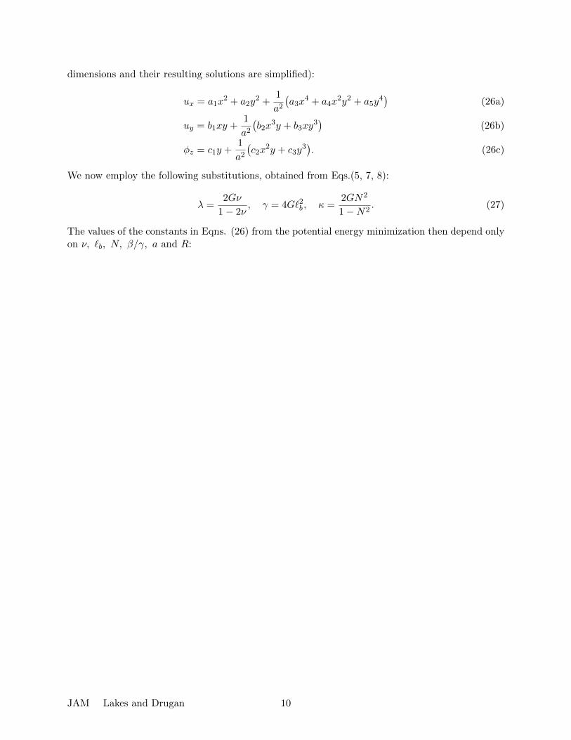
dimensions and their resulting solutions are simplified):
ux = a1x2 + a2y
2 +1
a2(a3x
4 + a4x2y2 + a5y
4)
(26a)
uy = b1xy +1
a2(b2x
3y + b3xy3)
(26b)
φz = c1y +1
a2(c2x
2y + c3y3). (26c)
We now employ the following substitutions, obtained from Eqs.(5, 7, 8):
λ =2Gν
1− 2ν, γ = 4G`2b , κ =
2GN2
1−N2. (27)
The values of the constants in Eqns. (26) from the potential energy minimization then depend onlyon ν, `b, N, β/γ, a and R:
JAM Lakes and Drugan 10

a1 = d
{N4(7− 19ν + 18ν2
)+ (`b/a)2N2
[371− 1294ν + 1052ν2
− 6N2(35 + 44ν − 156ν2 + 98ν3
) ]+ 18(`b/a)4
[245− 952ν + 728ν2
− 12N4(7− 4ν − 31ν2 + 28ν3
)− 4N2
(112 + 81ν − 486ν2 + 266ν3
) ]}a2 = −a1
4− 3ν + ν2
ν2+ 2a3
44− 109ν + 56ν2
7ν2− a4
4 + 13ν − 8ν2
3ν2
a3 =7
6
[3a1 + (1 + ν)a4][(a/`b)2/18 + 1/N2 − 1]− νa4
3 + [1/N2 + (a/`b)2/18](4− 7ν)
a4 = −21d
{N4(1− ν)2 + (`b/a)2N2
[53− 147ν + 88ν2 − 6N2
(5− 9ν + 4ν2
) ]+ 18(`b/a)4
[35− 111ν + 70ν2 − 12N4
(1− 3ν + 2ν2
)− 2N2
(32− 64ν + 29ν2
) ]}a5 = a1
19− 3ν
6ν2− a3
209− 565ν + 287ν2
21ν2+ a4
19 + 73ν − 44ν2
18ν2
b1 = a11− 4ν + 2ν2
ν2− (1− 2ν)
(2a3
11− 14ν
7ν2− a4
1 + 2ν
3ν2
)b2 = −4
1− νν
a3 (28)
b3 = −2(1− ν)
3ν(3a1 + a4)− b1
c1 = −6a2 + 3(b1 + b2)
(1− 2N2
)+ 2
(a4 + c2N
2)
6N2
c2 =3b2/2− a4
1 + 18(`b/a)2(1/N2 − 1)
c3 = b3 −4a5 + b3
2N2
where
d =15(`b/a)2N2(β/γ + ν)
4R/
{N6(22− 19ν) + 3(`b/a)2N4
[462− 399ν +N2
(301− 612ν + 290ν2
) ]+ 270(`b/a)6
[12N6(1− ν)2(5− 14ν) + 7(22− 19ν) +N2
(767− 1522ν + 728ν2
)+ 4N4
(139− 438ν + 432ν2 − 133ν3
) ]+ 3(`b/a)4N2
[305(22− 19ν)
+ 3N2(4439− 9172ν + 4435ν2
)+ 6N4
(407− 1357ν + 1195ν2 − 245ν3
) ]}.
Observe that the b2 term in Eqns. (26) represents the sigmoid bulge. The magnitude of thebulge effect is governed by d ∝ (βγ + ν), as expected. If `b << a, then d ∝ ( `ba )2; see Eqns. (30)below.
As these expressions for the constants simplify substantially for a specific ν value, we presenttheir reduced forms for the case ν = 0.3, which applies to the 0.4 mm cell size foam tested (the ci
JAM Lakes and Drugan 11
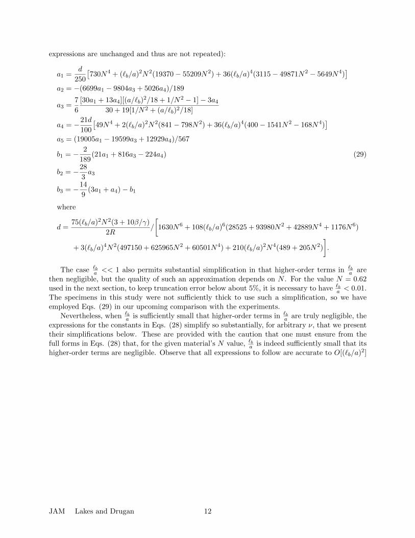
expressions are unchanged and thus are not repeated):
a1 =d
250
[730N4 + (`b/a)2N2(19370− 55209N2) + 36(`b/a)4(3115− 49871N2 − 5649N4)
]a2 = −(6699a1 − 9804a3 + 5026a4)/189
a3 =7
6
[30a1 + 13a4][(a/`b)2/18 + 1/N2 − 1]− 3a4
30 + 19[1/N2 + (a/`b)2/18]
a4 = −21d
100
[49N4 + 2(`b/a)2N2(841− 798N2) + 36(`b/a)4(400− 1541N2 − 168N4)
]a5 = (19005a1 − 19599a3 + 12929a4)/567
b1 = − 2
189(21a1 + 816a3 − 224a4) (29)
b2 = −28
3a3
b3 = −14
9(3a1 + a4)− b1
where
d =75(`b/a)2N2(3 + 10β/γ)
2R/
[1630N6 + 108(`b/a)6(28525 + 93980N2 + 42889N4 + 1176N6)
+ 3(`b/a)4N2(497150 + 625965N2 + 60501N4) + 210(`b/a)2N4(489 + 205N2)
].
The case `ba << 1 also permits substantial simplification in that higher-order terms in `b
a arethen negligible, but the quality of such an approximation depends on N . For the value N = 0.62used in the next section, to keep truncation error below about 5%, it is necessary to have `b
a < 0.01.The specimens in this study were not sufficiently thick to use such a simplification, so we haveemployed Eqs. (29) in our upcoming comparison with the experiments.
Nevertheless, when `ba is sufficiently small that higher-order terms in `b
a are truly negligible, theexpressions for the constants in Eqs. (28) simplify so substantially, for arbitrary ν, that we presenttheir simplifications below. These are provided with the caution that one must ensure from thefull forms in Eqs. (28) that, for the given material’s N value, `ba is indeed sufficiently small that itshigher-order terms are negligible. Observe that all expressions to follow are accurate to O[(`b/a)2]
JAM Lakes and Drugan 12

except that for b1, which for similar accuracy has terms through O[(`b/a)4] retained:
a1 = d(7− 19ν + 18ν2
), a2 = d
(25− ν − 18ν2
), a3 = −7
2dν(3− ν)
a4 = −21d(1− ν)2, a5 = −7
6d(44− 35ν − 3ν2
)b1 = 2d
{(1− ν)(5− 18ν)
+
(`ba
)2 [ 1
N2
(258− 197ν − 82ν2
)+
3(1− ν)
22− 19ν
(3203− 1836ν − 2758ν2 + 1496ν3
)]}b2 = 14d(3− ν)(1− ν), b3 = 14dν(1− ν), c1 = − 2d
N2
[22− 19ν − 6N2(1− ν)(2− 3ν)
]c2 = 42d(2− ν)(1− ν), c3 =
14d
3N2
[22− 19ν + 3N2ν(1− ν)
]where
d =15
4
β/γ + ν
22− 19ν
(`b/a)2
R.
(30)
3.5 Comparison of Approximate Cosserat Solution with Experimental Mea-surements
To compare the approximate solution obtained in the previous subsection with the experimentalmeasurements, we employ the following values corresponding to the foam bars tested:
a = 25mm, R = 27.5cm. (31)
Because the foam with the 1.2 mm cells is anisotropic (modulus ratio about 1.6), and the approxi-mate solution is for an isotropic Cosserat material, we compare our results with the measurementson the foam with the 0.4 mm cell size. The Poisson’s ratio of this foam was measured previously [26]to be approximately 0.3, the value also given by [1] as the mean of many measurements by variousauthors. We choose β/γ = 1 based on the results of [27], who performed homogenization analysisof a 3-D cubic lattice. If one tunes the rigidity of diagonal members in their lattice to obtain elasticisotropy, then β
γ → 1. No Cosserat model was available for foam. The approximate analyticalsolution does show that one must have β/γ > 0 to produce the same bulge sign as observed inthe experiments. The solution also shows that the bulge displacement magnitude increases withincreasing β/γ (whose maximum permissible value is 1).
With a,R, ν and β/γ so specified, the displacement field approximate solution contains onlythe unknowns `b and N . These are obtained by matching the analytical displacement field withthe experimental measurements for the smallest possible `b. The values thus obtained are
`b = 4.5mm, N2 = 0.39. (32)
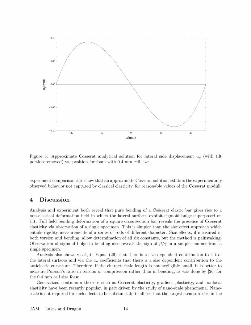
These values have been used in the plot of our approximate analytical solution for uy shown inFigure 5 where, as was done in the presentation of the experimental data, we have plotted the fulluy with the tilt (linear) portion removed in such a way that the displacement at the cross-sectioncorners vanishes. Observe the qualitative, as well as quantitative, agreement with the experimentalmeasurements reported in the right plot of Figure 3.
A single bending experiment cannot determine all Cosserat moduli. Our goal in this theory-
JAM Lakes and Drugan 13
-20 -10 0 10 20-0.10
-0.05
0.00
0.05
0.10
xHmmL
u yHm
mL
Figure 5: Approximate Cosserat analytical solution for lateral side displacement uy (with tiltportion removed) vs. position for foam with 0.4 mm cell size.
experiment comparison is to show that an approximate Cosserat solution exhibits the experimentally-observed behavior not captured by classical elasticity, for reasonable values of the Cosserat moduli.
4 Discussion
Analysis and experiment both reveal that pure bending of a Cosserat elastic bar gives rise to anon-classical deformation field in which the lateral surfaces exhibit sigmoid bulge superposed ontilt. Full field bending deformation of a square cross section bar reveals the presence of Cosseratelasticity via observation of a single specimen. This is simpler than the size effect approach whichentails rigidity measurements of a series of rods of different diameter. Size effects, if measured inboth torsion and bending, allow determination of all six constants, but the method is painstaking.Observation of sigmoid bulge in bending also reveals the sign of β/γ in a simple manner from asingle specimen.
Analysis also shows via b1 in Eqns. (26) that there is a size dependent contribution to tilt ofthe lateral surfaces and via the an coefficients that there is a size dependent contribution to theanticlastic curvature. Therefore, if the characteristic length is not negligibly small, it is better tomeasure Poisson’s ratio in tension or compression rather than in bending, as was done by [26] forthe 0.4 mm cell size foam.
Generalized continuum theories such as Cosserat elasticity, gradient plasticity, and nonlocalelasticity have been recently popular, in part driven by the study of nano-scale phenomena. Nano-scale is not required for such effects to be substantial; it suffices that the largest structure size in the
JAM Lakes and Drugan 14
material be non-negligible in comparison with representative size scales associated with gradients inapplied fields of stress, electric polarization or other fields, holes, notches or cracks, or at least onestructural component dimension. Nonlocal elasticity also provides additional freedom not presentin the classical theory. The nonlocal theory incorporates long range interactions between particlesin a continuum model. Such long range interactions occur between charged atoms or moleculesin a solid. Long range forces may also be considered to propagate along fibers or laminae in acomposite material [28] or in inclusions in random composites [29]. Nonlocality is often presentedin a differential form that entails an approximation to the nonlocal integral [30]. Such a formulationintroduces sensitivity to gradients of the stress or strain. Such gradient forms, termed nonlocal,have been presented [31] in the context of nano-scale systems. Cosserat elasticity reduces to agradient form when κ → ∞ or equivalently N → 1, so there are points of contact between theseformulations.
The toughness of foams [1] increases as the cell size `cell. Observe that toughness depends onstructure size. This is in contrast with the theory of elasticity, which has no length scale withinthe theory. Cosserat elasticity is therefore considered to be pertinent to toughness.
5 Conclusions
Pure bending of a square cross section bar gives rise to a sigmoidal deformation of the lateralsurfaces in addition to the usual tilt. This is shown both by a theoretical analysis of the bar asa isotropic Cosserat elastic solid, and by experiment on a bar of polymer foam. Observation ofdeformation of a single specimen reveals the presence of Cosserat elastic effects.
6 Acknowledgements
We gratefully acknowledge support of this research by the National Science Foundation via GrantCMMI-1361832.
References
[1] Gibson, L. J. and Ashby, M. F., 1997, Cellular Solids, Pergamon, Oxford; 2nd Ed., Cambridge.[2] Cosserat, E. and Cosserat, F., 1909, Theorie des Corps Deformables, Hermann et Fils, Paris.[3] Eringen, A.C., 1968, Theory of micropolar elasticity. In Fracture 1, 621-729 (edited by H. Liebowitz),
Academic Press.[4] Hadjesfandiari, A. R. and Dargush, G. F., 2011, Couple stress theory for solids, Int. J. Solids, Structures
48, pp. 2496-2510.[5] Koiter, W. T., 1964, Couple-Stresses in the theory of elasticity, Parts I and II, Proc. Koninklijke Ned.
Akad. Wetenshappen 67, pp. 17-44.[6] Lakes, R. S., 1986, Experimental microelasticity of two porous solids, Int. J. Solids and Structures, 22,
pp. 55-63.[7] Anderson, W. B. and Lakes, R. S., 1994, Size effects due to Cosserat elasticity and surface damage in
closed-cell polymethacrylimide foam, Journal of Materials Science, 29, pp. 6413-6419.[8] Spadoni, A. and Ruzzene, M., 2012, Elasto-static micropolar behavior of a chiral auxetic lattice, Journal
of the Mechanics and Physics of Solids 60, 156-171.[9] Adomeit, G., 1967, Determination of elastic constants of a structured material, Mechanics of Generalized
Continua, (Edited by Kroner, E.), IUTAM Symposium, Freudenstadt, Stuttgart. Springer, Berlin.[10] Bigoni, D. and Drugan, W., 2007, Analytical Derivation of Cosserat Moduli via Homogenization of
Heterogeneous Elastic Materials, J. Appl. Mech. 74, pp. 741 - 753.[11] Lakes, R. S., 1995, On the torsional properties of single osteons, J. Biomechanics, 28, pp. 1409-1410.
JAM Lakes and Drugan 15

[12] Gauthier, R. D. and W. E. Jahsman, 1975, A quest for micropolar elastic constants. J. Applied Me-chanics, 42, pp. 369-374.
[13] Mora, R. and Waas, A. M., 2000, Measurement of the Cosserat constant of circular cell polycarbonatehoneycomb, Philosophical Magazine A 80, pp. 1699-1713.
[14] Sikon, M., 2009, Theory and experimental verification of thermal stresses in Cosserat medium, Bulletinof the Polish Academy of Sciences: Technical Sciences, 57(2), pp. 177 - 180.
[15] Krishna Reddy, G. V. and Venkatasubramanian, N. K., 1978, On the flexural rigidity of a micropolarelastic circular cylinder, J. Applied Mechanics 45, pp. 429-431.
[16] Park, H. C. and R. S. Lakes, 1987, Torsion of a micropolar elastic prism of square cross section. Int. J.Solids, Structures, 23, pp. 485-503.
[17] Park, H. C. and Lakes, R. S., 1986, Cosserat micromechanics of human bone: strain redistribution bya hydration-sensitive constituent, J. Biomechanics, 19,pp. 385-397.
[18] Lakes, R. S., Gorman, D., and Bonfield, W., 1985, Holographic screening method for microelastic solids,J.Materials Science, 20, pp. 2882-2888.
[19] Anderson, W. B., Lakes, R. S., and Smith, M. C., 1995, Holographic evaluation of warp in the torsionof a bar of cellular solid, Cellular Polymers, 14, pp. 1-13.
[20] Iesan, D., 1971, On Saint Venant’s problem in micropolar elasticity, Int. J. Engng Sci. 9, pp. 879-888.[21] Iesan, D., 1971, Bending of a micropolar elastic beam by terminal couples. Analele Stiintifice Universi-
tatii Iasi Mathematica 17, pp. 483-490.[22] Reissner, E., 1968, On St. Venant flexure including couple stresses, PMM 32, pp. 923-929.[23] Park, S. K. and Gao, X. L., Bernoulli Euler beam model based on a modified couple stress theory, J.
Micromech. Microeng 16, pp. 2355-2359.[24] Jemielita, G., 2006, Bending of a micropolar rectangular prism.I. Bull. Polish Acad. Sciences Tech. Sci.
32, pp. 625-632 1984[25] Foamade Industries, Auburn Hills, MI.[26] Wang, Y. C., Lakes, R. S., and Butenhoff, A., 2001, Influence of cell size on re-entrant transformation
of negative Poisson’s ratio reticulated polyurethane foams, Cellular Polymers 20, pp. 373-385.[27] Tauchert, T., 1970, A lattice theory for representation of thermoelastic composite materials, Recent
Advances in Engineering Science, 5, pp. 325-345.[28] Ilcewicz, L., Kennedy, T. C., and Shaar, C., 1985, Experimental application of a generalized continuum
model to nondestructive testing, J. Materials Science Letters 4, pp. 434-438.[29] Drugan, W. J., 2003, Two Exact Micromechanics-Based Nonlocal Constitutive Equations for Random
Linear Elastic Composite Materials, Journal of the Mechanics and Physics of Solids 51, pp. 1745-1772.[30] Eringen, A. C. 1983, On differential equations of nonlocal elasticity and solutions of screw dislocations
and surface waves, J. Appl. Phys. 54, pp. 4703-4710[31] Peddieson, J. Buchanan, G. R., McNitt, R. P., 2003, Application of nonlocal continuum models to
nanotechnology, Int. J. Engng. Sci. 41, pp. 304-312.
JAM Lakes and Drugan 16


![Solid Simulation with Oriented Particles · pers, [Pai 2002] simulates elastic rods such as hair, wire and threads using the Cosserat theory by formulating a Boundary Value Prob-lem](https://img.pdfslide.us/doc/110x75/60912bc51cbdd57c9a05776b/solid-simulation-with-oriented-particles-pers-pai-2002-simulates-elastic-rods.jpg)