Embed Size (px)
Citation preview
Bender Element System (BES)
Key Features: Benefits to the User:USB interface: Allows the system to be swapped to any PC in the lab with a USB interface.Titanium element inserts: Reduces the weight of the top-cap.
Utilising existing products: Pedestals and top-caps can be made for other manufacturers’ cells as well as GDS cells, so upgrading is potentially simple.
The GDS Bender elements are bonded into a standard insert:
This makes the bender element insert a modular device that can then be easily fitted into a suitably modified pedestal/top-cap. Should an element fail, it is simple and quick for the complete insert to be replaced by the customer
2 Mega Samples/Second, 16bit Data Acquisition:
High speed data acquisition is essential as the sample interval provides the resolution for determining wave speeds.
Elements are manufactured to allow S and P wave testing to be performed:
Determining both S & P wave velocities allows additional specimen parameters to be calculated, such as Youngs Molulus, E.
Vertical and horizontal elements are available:
Specimen anisotropy can be studied with the use of both vertical and horizontal elements on the sample.
Technical Specification:
Data acquisition speed: 2,000,000 samples/second, simultaneous sampling of both source and received signals.
Resolution of data acquisition (bits): 16Computer Interface: USBAvailable gain ranges for data acquisition: From x10 to x500
Operating Temperature: -10°C to 50°CSample Sizes: Up to 300mm
Tests that can be Performed:Determination of Shear Wave Velocity, determination of P-Wave Velocity, vertically propogating horizontally polarised (vertical elements), horizontally propogating horizontally polarised (horizontal elements), horizontally propogating vertically polarised (horizontal elements).
Upgrade Options:• Combined pedestals for unsaturated testing and bender elements (ie with bonded high air entry porous disc).
The GDS Bender Element system enables easy measurement of the maximum shear modulus of a soil at small strains in a triaxial cell. Measurement of soil stiffness at very small strains in the laboratory is difficult due to insufficient resolution and accuracy of load and displacement measuring devices. The capability exists to regularly carry out measurements of small strain stiffness in the triaxial apparatus using local strain transducers, but this can be expensive and is generally confined to research projects.
The addition of Bender Elements to a triaxial testing system makes the routine measurement of Gmax, maximum shear modulus, simple and cost effective.
www.gdsinstruments.com
World leaders in the manufacture of laboratory systems for soil & rock
GDSBES Hardware
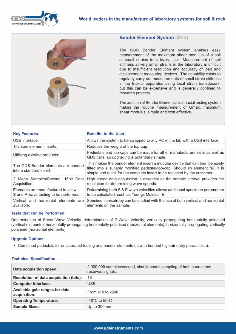
The full GDS-BES system is made up of the following; Bender Element Inserts, adapted pedestal and topcap, an external USB control box and the GDSBES Software.
The Bender Element is encapsulated and mounted in inserts that can be fixed in either the topcap or the base pedestal. Both inserts are manufactured from titanium so that they can be mounted in either base pedestal or top-cap. As well as its high axial rigidity, titanium is used for its low weight to minimize the imposed axial load when fitted to a sample top-cap.
If the bender element insert is to be fitted to another manufacturers’ equipment (that we are not familiar with) full mounting information can be provided to GDS to enable us to manufacture custom pedestals for your specific equipment.
System Purchase Options:
The GDS Bender Element System can be supplied in different levels of completeness depending on the users requirements:
• Level 1, encapsulated bender elements mounted in the inserts only. For use where a customer already has a driving system, signal conditioning, and data acquisition system (e.g. an oscilloscope).
• Level 2, The full GDS bender element system including the bender element inserts, signal conditioning and control box and GDS-BES software.
Receiver Control:
Where a full GDS bender element system is being used the software will automatically switch input gain levels (of the received signal), set the level of the output signal voltage and control switching between the P and S wave modes for the combined wave type elements. The software will select an appropriate sampling rate, which the user may override if required.
The acquired data is presented to the user for picking of both the source (feedback) signal and the received signal. Picking of the source signal gives an absolute zero to the calculation of travel time and does not rely on trigger detection.
Acquired data can be saved in ASCII format for plotting or use in reporting (see also GDS BEAT Analysis Tool on the following page).
www.gdsinstruments.com
World leaders in the manufacture of laboratory systems for soil & rock
Bender elements for Horizontally Propagating Waves
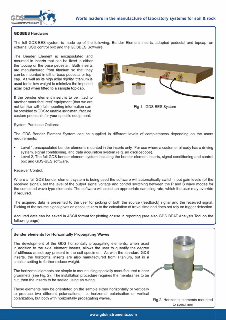
The development of the GDS horizontally propagating elements, when used in addition to the axial element inserts, allows the user to quantify the degree of stiffness anisotropy present in the soil specimen. As with the standard GDS inserts, the horizontal inserts are also manufactured from Titanium, but in a smaller setting to further reduce weight.
The horizontal elements are simple to mount using specially manufactured rubber grommets (see Fig. 2). The installation procedure requires the membranes to be cut, then the inserts to be sealed using an o-ring.
These elements may be orientated on the sample either horizontally or vertically to produce two different polarisations, i.e. horizontal polarisation or vertical polarization, but both with horizontally propagating waves. Fig 2. Horizontal elements mounted
to specimen
Fig 1. GDS BES System
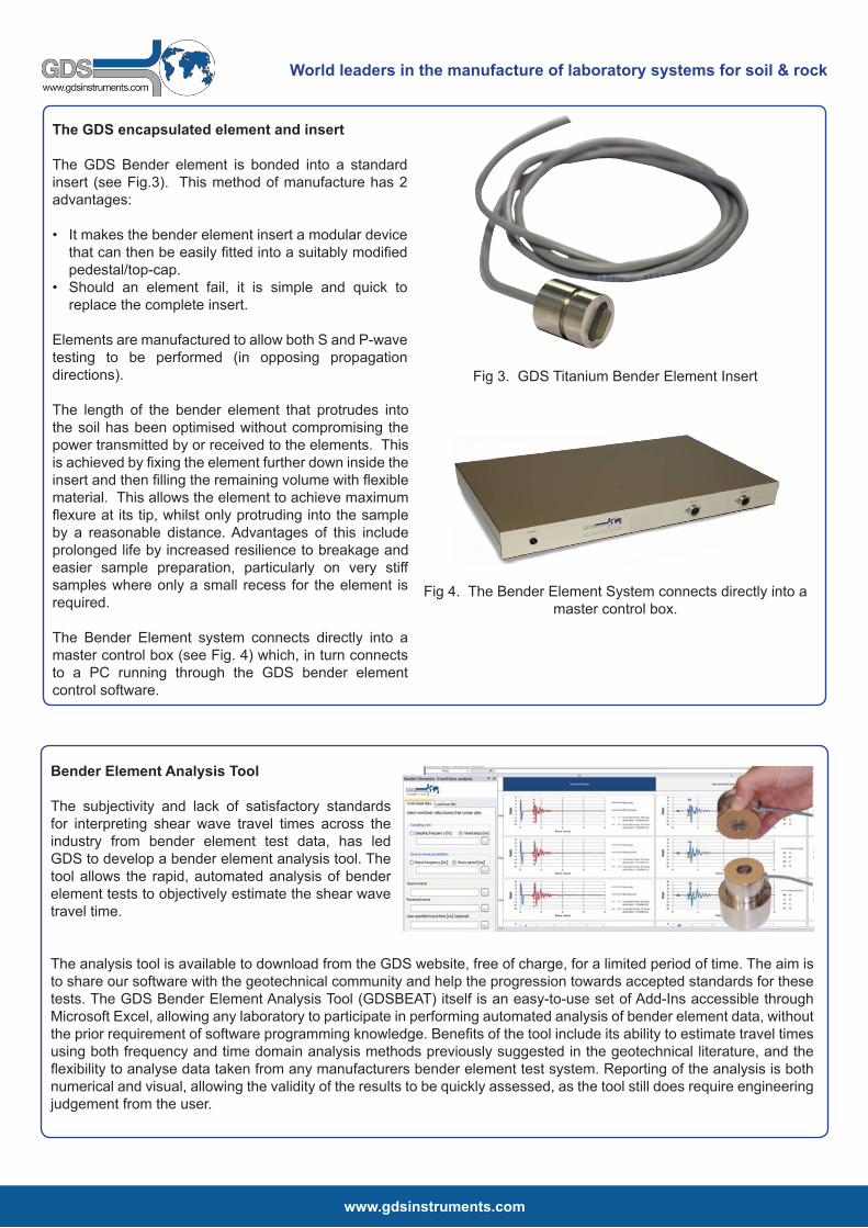
The GDS encapsulated element and insert
The GDS Bender element is bonded into a standard insert (see Fig.3). This method of manufacture has 2 advantages:
• It makes the bender element insert a modular device that can then be easily fitted into a suitably modified pedestal/top-cap.
• Should an element fail, it is simple and quick to replace the complete insert.
Elements are manufactured to allow both S and P-wave testing to be performed (in opposing propagation directions). The length of the bender element that protrudes into the soil has been optimised without compromising the power transmitted by or received to the elements. This is achieved by fixing the element further down inside the insert and then filling the remaining volume with flexible material. This allows the element to achieve maximum flexure at its tip, whilst only protruding into the sample by a reasonable distance. Advantages of this include prolonged life by increased resilience to breakage and easier sample preparation, particularly on very stiff samples where only a small recess for the element is required.
The Bender Element system connects directly into a master control box (see Fig. 4) which, in turn connects to a PC running through the GDS bender element control software.
www.gdsinstruments.com
World leaders in the manufacture of laboratory systems for soil & rock
Fig 4. The Bender Element System connects directly into a master control box.
Fig 3. GDS Titanium Bender Element Insert
Bender Element Analysis Tool
The subjectivity and lack of satisfactory standards for interpreting shear wave travel times across the industry from bender element test data, has led GDS to develop a bender element analysis tool. The tool allows the rapid, automated analysis of bender element tests to objectively estimate the shear wave travel time.
The analysis tool is available to download from the GDS website, free of charge, for a limited period of time. The aim is to share our software with the geotechnical community and help the progression towards accepted standards for these tests. The GDS Bender Element Analysis Tool (GDSBEAT) itself is an easy-to-use set of Add-Ins accessible through Microsoft Excel, allowing any laboratory to participate in performing automated analysis of bender element data, without the prior requirement of software programming knowledge. Benefits of the tool include its ability to estimate travel times using both frequency and time domain analysis methods previously suggested in the geotechnical literature, and the flexibility to analyse data taken from any manufacturers bender element test system. Reporting of the analysis is both numerical and visual, allowing the validity of the results to be quickly assessed, as the tool still does require engineering judgement from the user.
www.gdsinstruments.com
World leaders in the manufacture of laboratory systems for soil & rock
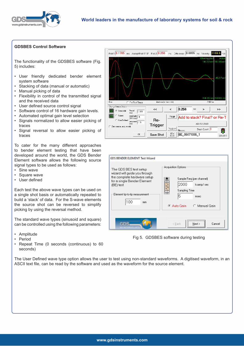
GDSBES Control Software
The functionality of the GDSBES software (Fig. 5) includes:
• User friendly dedicated bender element system software
• Stacking of data (manual or automatic)• Manual picking of data• Flexibility in control of the transmitted signal
and the received data• User defined source control signal• Software control of 16 hardware gain levels. • Automated optimal gain level selection• Signals normalized to allow easier picking of
traces• Signal reversal to allow easier picking of
traces
To cater for the many different approaches to bender element testing that have been developed around the world, the GDS Bender Element software allows the following source signal types to be used as follows:• Sine wave• Square wave• User defined
Each test the above wave types can be used on a single shot basis or automatically repeated to build a ‘stack’ of data. For the S-wave elements the source shot can be reversed to simplify picking by using the reversal method.
The standard wave types (sinusoid and square) can be controlled using the following parameters:
• Amplitude• Period• Repeat Time (0 seconds (continuous) to 60
seconds)
The User Defined wave type option allows the user to test using non-standard waveforms. A digitised waveform, in an ASCII text file, can be read by the software and used as the waveform for the source element.
Fig 5. GDSBES software during testing

World leaders in the manufacture of laboratory systems for soil & rock
GDS Instruments ● Tel: +44 (0) 1256 382450 ● Fax: +44 (0) 1256 382451 ● e: [email protected] ● Web: www.gdsinstruments.com
Due to continued development, specifications may change without notice. See the GDS website for the full product range & to visit our Geotechnical Learning Zone.
Technical Support:
GDS provide comprehensive on-site product training and installation. GDS understand the need for ongoing after sales support, so much so that they have their own dedicated customer support centre. The support centre allows the user to log queries, download helpsheets and get the latest information on product updates. The site is fully searchable and provides a great resource to customers.
Alongside their support centre GDS use a variety of additional support methods including...
• Remote PC Support: Remote PC support works by GDS providing a secure link to a customers PC, thereby allowing GDS to take control. Once in control of the PC, GDS can help with any problems associated to software, installation, testing etc.
• Product Helpsheets: The helpsheets are the GDS FAQ documents. They cover a multitude of hardware and software questions and are free to download from our online support centre.
• YouTube Channel: GDS YouTube channel holds both software and hardware video’s aimed to give you better understanding of how the products work.
• Email & Telephone Support: If you prefer you can email requests to [email protected] where they will be automatically added to the support system and then allocated to a support engineer.
Made in the UK:
All GDS products are designed, manufactured and assembled in the UK at our offices in Hook. Quality assurance is taken of all products before they are dispatched.
GDS are an ISO9001:2000 accredited company. The scope of this certificate applies to the approved quality administration systems relating to the “Manufacture of Laboratory and Field Testing Equipment”.
Why Buy GDS?
GDS Awarded Queens Award for Enterprise in International Trade:
GDS have been presented with the most prestigious corporate award made in the UK – The Queen’s Award for Enterprise in the International Trade category. GDS are delighted to have won the award which has been given to GDS for increasing overseas trade by 190% over six years of continuous sustained growth, and for selling over 85% of their production overseas. GDS have achieved this through a combination of continuous product development, understanding customer’s requirements and a company wide dedication to customer support.
Fig 8. GDS online customer support centre.