Embed Size (px)
Citation preview

BELT & DISC SANDERMODEL NO: CS4-6E
PART NO: 6500413
OPERATION & MAINTENANCEINSTRUCTIONS
LS1017
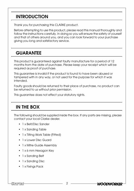
INTRODUCTION
Thank you for purchasing this CLARKE product.
Before attempting to use this product, please read this manual thoroughly and follow the instructions carefully. In doing so you will ensure the safety of yourself and that of others around you, and you can look forward to your purchase giving you long and satisfactory service.
GUARANTEE
This product is guaranteed against faulty manufacture for a period of 12 months from the date of purchase. Please keep your receipt which will be required as proof of purchase.
This guarantee is invalid if the product is found to have been abused or tampered with in any way, or not used for the purpose for which it was intended.
Faulty goods should be returned to their place of purchase, no product can be returned to us without prior permission.
This guarantee does not effect your statutory rights.
IN THE BOX
The following should be supplied inside the box. If any parts are missing, please contact your local Clarke dealer.
• 1 x Belt/Disc Sander
• 1 x Sanding Table
• 1 x Tilting Work Table (Fitted)
• 1 x Lower Disc Guard
• 1 x Mitre Guide Assembly
• 1 x 6 mm Hexagon Key
• 1 x Sanding Belt
• 1 x Sanding Disc
• 1 x Fixings Pack
2

GENERAL SAFETY RULES
1. ALWAYS learn the machines applications, limitations and the specific potential hazards. Read and become familiar with the entire operating manual.
1. ALWAYS use a face or dust mask if the operation is particularly dusty.
2. AlWAYS check for damage before using the machine, check for alignment of moving parts, breakage of parts, and any other condition that may affect the machines operation. Damage should be properly repaired or the part replaced. If in doubt, DO NOT use the machine. Consult your local dealer.
3. ALWAYS disconnect the machine from the power supply before servicing and when changing accessories.
4. ALWAYS wear safety goggles, manufactured to the latest European Safety Standards. Everyday eyeglasses do not have impact resistant lenses, and are not safety glasses.
5. ALWAYS keep work area clean. Cluttered areas and benches invite accidents.
6. ALWAYS ensure that adequate lighting is available. Ensure that lighting is placed so that you will not be working in your own shadow.
7. ALWAYS keep children away. All visitors should be kept a safe distance from the work area, especially when the machine is being used.
8. ALWAYS maintain machine in top condition. Keep tools/machines clean for the best and safest performance. Follow maintenance instructions.
9. ALWAYS handle with extreme care and do not carry the tool/machine by its electric cable, or pull on the cable to disconnect it from the power supply.
10. ALWAYS ensure the switch is off before plugging in to mains. Avoid accidental starting.
11. ALWAYS concentrate on the job in hand, no matter how trivial it may seem. Be aware that accidents are caused by carelessness due to familiarity.
12. ALWAYS keep your proper footing and balance at all times - don’t overreach. For best footing, wear rubber soled footwear. Keep floor clear of oil, scrap wood, etc.
13. ALWAYS dress properly. Loose clothing or jewellery may get caught in moving parts. Wear protective hair covering to contain long hair.
14. ALWAYS guard against electric shock. Avoid contact with earthed surfaces - pipes, radiators etc.
3

15. NEVER operate machine while under the influence of drugs, alcohol or any medication.
16. NEVER leave machine running unattended. Turn power off. Do not leave the machine until it comes to a complete stop.
17. NEVER force the machine, it will do a better and safer job at the rate for which it was designed.
18. NEVER use power tools in damp or wet locations or expose them to rain. Do not use in an explosive atmosphere (around paint, flammable liquids etc.). Avoid dangerous environments.
19. If the tool begins to make an abnormal noise, or produce excessive vibrations, smoke or burning odour, turn the tool off immediately and do not operate, until repaired.
EXTRA PRECAUTIONS FOR BELT/DISC SANDERS
1. ALWAYS wear ear protectors/defenders when using this machine.
2. ALWAYS wear a dust mask when using this machine. Be aware that harmful or toxic dusts could be produced when sanding some woods.
3. ALWAYS use the table to support the workpiece.
4. ALWAYS check to ensure the table and attachments are secure before starting.
5. ALWAYS maintain a clearance of 2-3mm between table and sanding disc.
6. ALWAYS hold the workpiece firmly so that it cannot be torn from your hands.
7. ALWAYS feed the workpiece against the direction of rotation of the disc. i.e the LEFT side of the disc.
8. ALWAYS keep the mains cable well away from the machine and ensure an adequate electrical supply is close at hand so that the operation is not restricted by the length of the cable.
9. ALWAYS use a dust extraction device, properly connected to the dust extraction port.
10. ALWAYS ensure that nails or foreign objects have been removed from a workpiece beforehand. Nails etc. will destroy the belt or disc.
11. NEVER allow the ventilation slots in the motor to become blocked.
12. NEVER sand pieces which cannot be held firmly by hand.
4

5
ELECTRICAL CONNECTIONS
Before switching the product on, make sure that the voltage of your electricity supply is the same as that indicated on the rating plate. This product is designed to operate on 230VAC 50Hz. Connecting it to any other power source may cause damage.
This product may be fitted with a non-rewireable plug. If it is necessary to change the fuse in the plug, the fuse cover must be refitted. If the fuse cover becomes lost or damaged, the plug must not be used until a suitable replacement is obtained.
If the plug has to be changed because it is not suitable for your socket, or due to damage, it should be cut off and a replacement fitted, following the wiring instructions shown below. The old plug must be disposed of safely, as insertion into a mains socket could cause an electrical hazard.
If the colours of the wires in the power cable of this product do not correspond with the markings on the terminals of your plug, proceed as follows.
• The wire which is coloured Blue must be connected to the terminal which is marked N or coloured Black.
• The wire which is coloured Brown must be connected to the terminal which is marked L or coloured Red.
• The wire which is coloured Yellow and Green must be connected to the
terminal which is marked E or or coloured Green.
We strongly recommend that this machine is connected to the mains supply via a Residual Current Device (RCD)
If in any doubt, consult a qualified electrician. DO NOT attempt any repairs yourself.
WARNING! Read these electrical safety instructions thoroughly before connecting the product to the mains supply.
WARNING! The wires in the power cable of this product are coloured in accordance with the following code:Blue = Neutral Brown = Live Yellow and Green = Earth
Plug must be BS1363/A approved.
Always fit a 13 Amp fuse.
Ensure that the outer sheath of the cable is firmly held by the clamp
Neutral(Blue)
Live(Brown)
Earth(Green and Yellow)
6
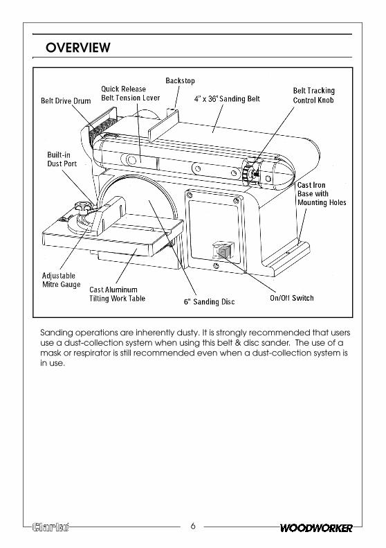
OVERVIEW
Sanding operations are inherently dusty. It is strongly recommended that users use a dust-collection system when using this belt & disc sander. The use of a mask or respirator is still recommended even when a dust-collection system is in use.
ASSEMBLY
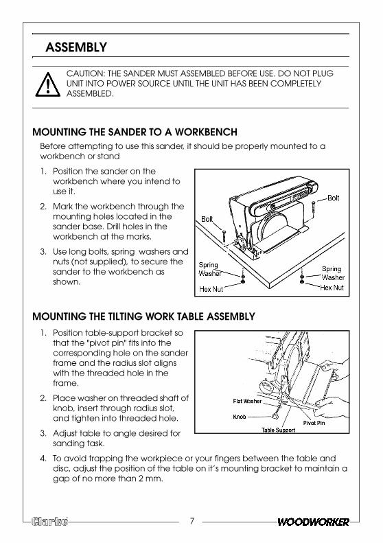
MOUNTING THE SANDER TO A WORKBENCHBefore attempting to use this sander, it should be properly mounted to a workbench or stand
1. Position the sander on the workbench where you intend to use it.
2. Mark the workbench through the mounting holes located in the sander base. Drill holes in the workbench at the marks.
3. Use long bolts, spring washers and nuts (not supplied), to secure the sander to the workbench as shown.
MOUNTING THE TILTING WORK TABLE ASSEMBLY1. Position table-support bracket so
that the "pivot pin" fits into the corresponding hole on the sander frame and the radius slot aligns with the threaded hole in the frame.
2. Place washer on threaded shaft of knob, insert through radius slot, and tighten into threaded hole.
3. Adjust table to angle desired for sanding task.
4. To avoid trapping the workpiece or your fingers between the table and disc, adjust the position of the table on it’s mounting bracket to maintain a gap of no more than 2 mm.
CAUTION: THE SANDER MUST ASSEMBLED BEFORE USE. DO NOT PLUG UNIT INTO POWER SOURCE UNTIL THE UNIT HAS BEEN COMPLETELY ASSEMBLED.
7

INSTALLING THE BACKSTOP1. Position the backstop against the
belt frame so that the slot alignswith threaded hole in frame.
2. Secure the backstop to frame with2 x socket head screws, washers as shown. Do not overtighten.
• The gap between the sandingbelt and the backstop shouldbe no more than 2mm.
ATTACHING A DUST COLLECTION HOSEThis sander is equipped with a 2½" (60 mm) diameter dust port that can be connected to a vacuum or dust-collection system.
1. Place a 2½” ID diameter hose overthe dust port.
Secure hose in place with a hose clamp.
8

CHANGING THE SANDING DISCS
1. Remove mitre gauge and worktable assembly.
2. Remove the disc guard screwsand disc guard.
3. Remove sanding disc from discplate. Sanding discs are attachedto the plate using a pressure-sensitive adhesive
4. Ensure the disc plate is clean.
5. Peel backing away from the newsanding disc.
6. Align perimeter of disc with plateand press disc firmly into positionon plate, leaving no loose edges.
7. Replace the disc guard, discguard screws and work table.
CONSUMABLES
Sanding discs are available from your Clarke dealer.
WARNING: TURN THE POWER OFF AND REMOVE THE PLUG FROM THE OUTLET BEFORE CHANGING THE ACCESSORIES.
CAUTION: ‘HOOK & LOOP’ SANDING DISCS CANNOT BE USED WITH THIS SANDER!
Grit Part number
Fine 6502097
Medium 6500809
Course 6502102
9
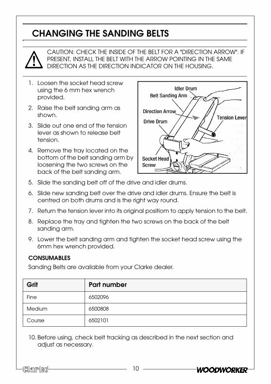
CHANGING THE SANDING BELTS
1. Loosen the socket head screwusing the 6 mm hex wrenchprovided.
2. Raise the belt sanding arm asshown.
3. Slide out one end of the tensionlever as shown to release belttension.
4. Remove the tray located on thebottom of the belt sanding arm byloosening the two screws on theback of the belt sanding arm.
5. Slide the sanding belt off of the drive and idler drums.
6. Slide new sanding belt over the drive and idler drums. Ensure the belt iscentred on both drums and is the right way round.
7. Return the tension lever into its original positiom to apply tension to the belt.
8. Replace the tray and tighten the two screws on the back of the beltsanding arm.
9. Lower the belt sanding arm and tighten the socket head screw using the6mm hex wrench provided.
CONSUMABLESSanding Belts are available from your Clarke dealer.
10. Before using, check belt tracking as described in the next section andadjust as necessary.
CAUTION: CHECK THE INSIDE OF THE BELT FOR A "DIRECTION ARROW". IF PRESENT, INSTALL THE BELT WITH THE ARROW POINTING IN THE SAME DIRECTION AS THE DIRECTION INDICATOR ON THE HOUSING.
Grit Part number
Fine 6502096
Medium 6500808
Course 6502101
10
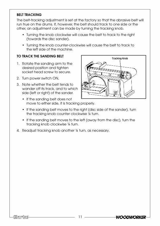
BELT TRACKINGThe belt-tracking adjustment is set at the factory so that the abrasive belt will run true on the drums. If, however, the belt should track to one side or the other, an adjustment can be made by turning the tracking knob.
• Turning the knob clockwise will cause the belt to track to the right (towards the disc sander).
• Turning the knob counter-clockwise will cause the belt to track to the left side of the machine.
TO TRACK THE SANDING BELT
1. Rotate the sanding arm to the desired position and tighten socket head screw to secure.
2. Turn power switch ON,
3. Note whether the belt tends to wander off its track, and to which side (left or right) of the sander.
• If the sanding belt does not move to either side, it is tracking properly.
• If the sanding belt moves to the right (disc side of the sander), turn the tracking knob counter clockwise ¼ turn.
• If the sanding belt moves to the left (away from the disc), turn the tracking knob clockwise ¼ turn.
4. Readjust tracking knob another ¼ turn, as necessary.
11
OPERATION
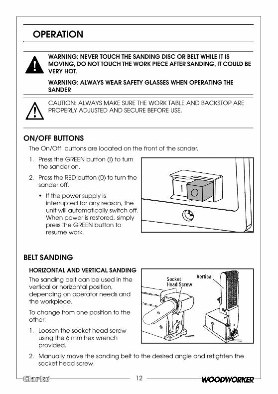
ON/OFF BUTTONSThe On/Off buttons are located on the front of the sander.
1. Press the GREEN button (I) to turnthe sander on.
2. Press the RED button (0) to turn thesander off.
• If the power supply isinterrupted for any reason, theunit will automatically switch off.When power is restored, simplypress the GREEN button toresume work.
BELT SANDING
HORIZONTAL AND VERTICAL SANDINGThe sanding belt can be used in the vertical or horizontal position, depending on operator needs and the workpiece.
To change from one position to the other:
1. Loosen the socket head screwusing the 6 mm hex wrenchprovided.
2. Manually move the sanding belt to the desired angle and retighten thesocket head screw.
WARNING: NEVER TOUCH THE SANDING DISC OR BELT WHILE IT IS MOVING, DO NOT TOUCH THE WORK PIECE AFTER SANDING, IT COULD BE VERY HOT.
WARNING: ALWAYS WEAR SAFETY GLASSES WHEN OPERATING THE SANDER
CAUTION: ALWAYS MAKE SURE THE WORK TABLE AND BACKSTOP ARE PROPERLY ADJUSTED AND SECURE BEFORE USE.
12
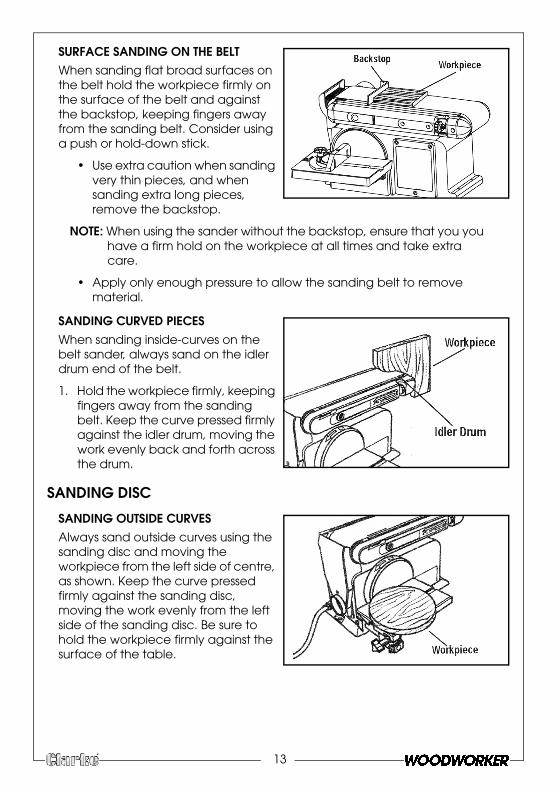
SURFACE SANDING ON THE BELTWhen sanding flat broad surfaces on the belt hold the workpiece firmly on the surface of the belt and against the backstop, keeping fingers away from the sanding belt. Consider using a push or hold-down stick.
• Use extra caution when sanding very thin pieces, and whensanding extra long pieces,remove the backstop.
NOTE: When using the sander without the backstop, ensure that you you have a firm hold on the workpiece at all times and take extra care.
• Apply only enough pressure to allow the sanding belt to removematerial.
SANDING CURVED PIECESWhen sanding inside-curves on the belt sander, always sand on the idler drum end of the belt.
1. Hold the workpiece firmly, keeping fingers away from the sandingbelt. Keep the curve pressed firmlyagainst the idler drum, moving thework evenly back and forth acrossthe drum.
SANDING DISC
SANDING OUTSIDE CURVESAlways sand outside curves using the sanding disc and moving the workpiece from the left side of centre, as shown. Keep the curve pressed firmly against the sanding disc, moving the work evenly from the left side of the sanding disc. Be sure to hold the workpiece firmly against the surface of the table.
13
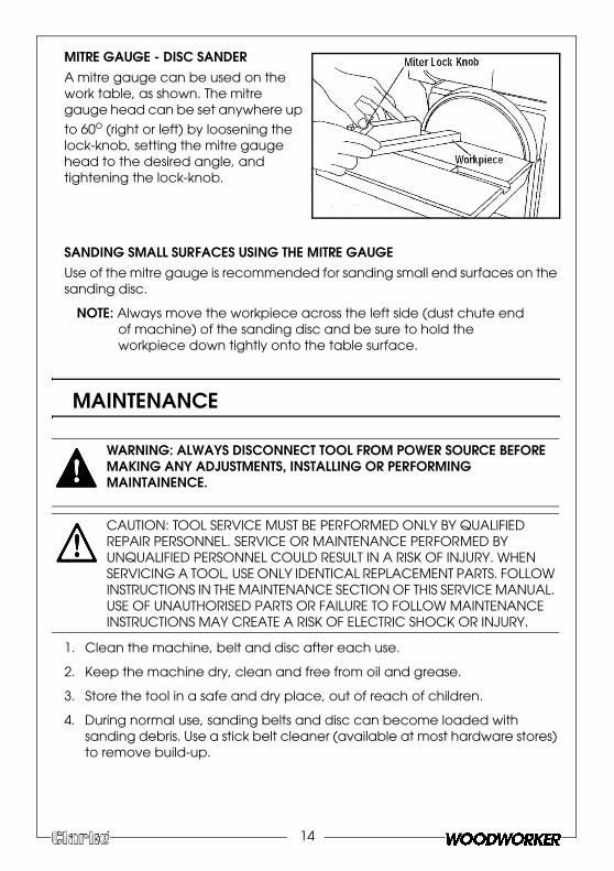
MITRE GAUGE - DISC SANDERA mitre gauge can be used on the work table, as shown. The mitre gauge head can be set anywhere up
to 60o (right or left) by loosening the lock-knob, setting the mitre gauge head to the desired angle, and tightening the lock-knob.
SANDING SMALL SURFACES USING THE MITRE GAUGEUse of the mitre gauge is recommended for sanding small end surfaces on the sanding disc.
NOTE: Always move the workpiece across the left side (dust chute end of machine) of the sanding disc and be sure to hold the workpiece down tightly onto the table surface.
MAINTENANCE
1. Clean the machine, belt and disc after each use.
2. Keep the machine dry, clean and free from oil and grease.
3. Store the tool in a safe and dry place, out of reach of children.
4. During normal use, sanding belts and disc can become loaded withsanding debris. Use a stick belt cleaner (available at most hardware stores)to remove build-up.
WARNING: ALWAYS DISCONNECT TOOL FROM POWER SOURCE BEFORE MAKING ANY ADJUSTMENTS, INSTALLING OR PERFORMING MAINTAINENCE.
CAUTION: TOOL SERVICE MUST BE PERFORMED ONLY BY QUALIFIED REPAIR PERSONNEL. SERVICE OR MAINTENANCE PERFORMED BY UNQUALIFIED PERSONNEL COULD RESULT IN A RISK OF INJURY. WHEN SERVICING A TOOL, USE ONLY IDENTICAL REPLACEMENT PARTS. FOLLOW INSTRUCTIONS IN THE MAINTENANCE SECTION OF THIS SERVICE MANUAL. USE OF UNAUTHORISED PARTS OR FAILURE TO FOLLOW MAINTENANCE INSTRUCTIONS MAY CREATE A RISK OF ELECTRIC SHOCK OR INJURY.
14
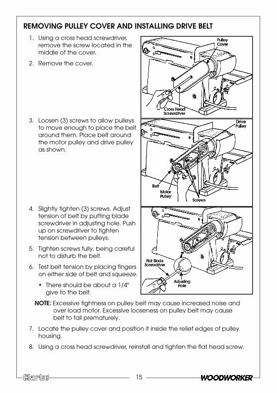
REMOVING PULLEY COVER AND INSTALLING DRIVE BELT1. Using a cross head screwdriver,
remove the screw located in themiddle of the cover.
2. Remove the cover.
3. Loosen (3) screws to allow pulleysto move enough to place the beltaround them. Place belt aroundthe motor pulley and drive pulleyas shown.
4. Slightly tighten (3) screws. Adjusttension of belt by putting bladescrewdriver in adjusting hole. Pushup on screwdriver to tightentension between pulleys.
5. Tighten screws fully, being carefulnot to disturb the belt.
6. Test belt tension by placing fingerson either side of belt and squeeze.
• There should be about a 1/4"give to the belt.
NOTE: Excessive tightness on pulley belt may cause increased noise and over load motor. Excessive looseness on pulley belt may cause belt to fail prematurely.
7. Locate the pulley cover and position it inside the relief edges of pulleyhousing.
8. Using a cross head screwdriver, reinstall and tighten the flat head screw.
15

16
SPECIFICATIONS
PARTS AND SERVICING
Motor 230V, 50Hz, 1ph
Input Power 370 Watts
Fuse Rating 13A
Sanding Disc Diameter 6” (150 mm)
Sanding Belt Size (W x L) 4” x 36” (914 x 100 mm)
Sanding Belt Speed 450m/min
Sanding Table Dimensions (L x W) 225 x 160 mm
Table Angle Range 0-45 degrees
Mitre Guide Angle Range 0-60 degrees
Net Weight 18.65 kg
Dimensions (LxWxH) 447 x 363 x 255 mm
Sound Pressure Level dB LpA 91.1 dB (A)
Sound Power Level dB LWA 79.9 dB (A)
Vibration 3.34 m/s2
Part No 6500413
For Parts & Servicing, please contact your nearest dealer, or
CLARKE International, on one of the following numbers.
PARTS & SERVICE TEL: 020 8988 7400PARTS & SERVICE FAX: 020 8558 3622
or e-mail as follows:PARTS: [email protected]
SERVICE: [email protected]
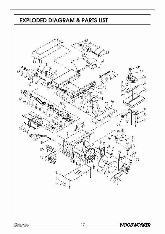
EXPLODED DIAGRAM & PARTS LIST
17

EXPLODED DIAGRAM & PARTS LIST
NO DESCRIPTION1 Philips Screw M4x6
2 Flat Washer D4
3 Base Cover
4 Philips Screw St4.2x10
5 Toothed Lock Washer D4
6 Disc Cover
7 Disc Paper
8 Hex Socket Round Head Screw M6x16
9 Toothed Lock Washer D6
10 Disc
11 Sanding Disc Guard
12 Phillips Screw M5x8
13 Spring Washer D5
14 Flat Washer D5
15 Toothed Lock Washer D5
16 Disc Rotation Label 5x10
17 Base
18 Phillips Screw St4.2x20
19 Wire Connection Box Cover
20 Phillips Screw St2.9x28
21 Relay
22 Wire Connection Box
23 Phillips Screw M5x10
24 Power Switch
25 Phillips Screw M6x8
26 Spring Washer D6
27 Hex Nut,type I M5
28 Capacitor
29 Capacitor Support
30 Phillips Screw M5x12
31 Hex Bolt M6x12
32 Big Flat Washer D6
33 Work Table Support Angle Plate
34 Miter Gauge Knob
35 Work Table
3
3
3
3
4
4
4
4
4
4
4
4
4
4
5
5
5
5
5
5
5
5
5
5
6
6
6
6
6
6
6
6
6
6
7
7
7
N
6 Cotter Pin
7 Miter Gauge Knob
8 Mitre Gauge
9 Cotter Pin
0 Tension Spring
1 Bushing
2 Joint Lever
3 Screw Bushing D12
4 Bearing 101
5 Idler Roller
6 Idler Shaft
7 Phillips Screw M5x20
8 Bushing
9 Connecting Rod
0 Tension Spring
1 Tension Knob
2 Big Flat Washer D5
3 Hex Nut,type I M6
4 Phillips Screw M5x16
5 Adjust Knob
6 Flat Washer D6
7 Rubber Washer
8 Adjust Spring
9 Belt Support
0 Limiting Plate
1 Driving Roller
2 Hex Socket Round Head Screw M8x12
3 Driving Shaft
4 Bearing Cap
5 Support Cover
6 Phillips Screw M5x10
7 Cog Belt Guard Cover
8 Phillips Screw M5x16
9 Special Locked Washer
0 Cog Belt
1 Driven Pulley
2 Phillips Screw M5x25
O DESCRIPTION7
7
7
7
7
7
7
8
8
8
8
8
8
8
8
8
8
9
9
9
9
N
18
Quote Part number AWNCS46D + Diagram number.
e.g Tension spring is AWNCS46D50
3 Bearing Base
4 Phillips Screw M6x25
5 Hex Socket Round Head Screw M8x25
6 Belt Cover
7 Square Nut
8 Motor Arbor Wheel
9 Phillips Screw M5x6
0 Belt Protection Plate
1 Motor Assy
2 Cord
3 Cord Clip
4 Dust Hood
5 Bracket Support
6 Belt
7 Flat Washer D8
8 Hex Cylinder Screw M8x16
9 Tension Pole
0 Roll Pin 5x8
1 Capacitor
2 Capacitor Support
3 Nut M8
O DESCRIPTION

19
DECLARATION OF CONFORMITY