Embed Size (px)
Citation preview

CI/SfB
(52.7) In6
OCTOBER 1999 OUIG4
BELOW GROUND DRAINAGE SYSTEMSINSTALLATION GUIDE
CONTENTS PAGE
Below Ground Drainage Systems
Resources and Planning 4
Transport 4
Handling 4
Storage 5
Installation Notes 6
Excavation 6
Bedding 6-7
Backfill Sequence 8
Pipe Protection 8-9
Installation of TwinWall Pipes 10-11
OsmaDrain System
Contents 12
Installation Information 13-34
Osma UltraRib System
Contents 35
Installation Information 36-45
Wavin TwinWall System
Contents 46
Installation Information 47-49
Below Ground Drainage Systems
Testing 50
Safety 50
Maintenance 50
General Information 51
Acceptance 52
Abbreviations 52
BELOW GROUND DRAINAGE SYSTEMS
Contents
3
B E L O W G R O U N D D R A I N A G E S Y S T E M S I N S T A L L A T I O N G U I D E
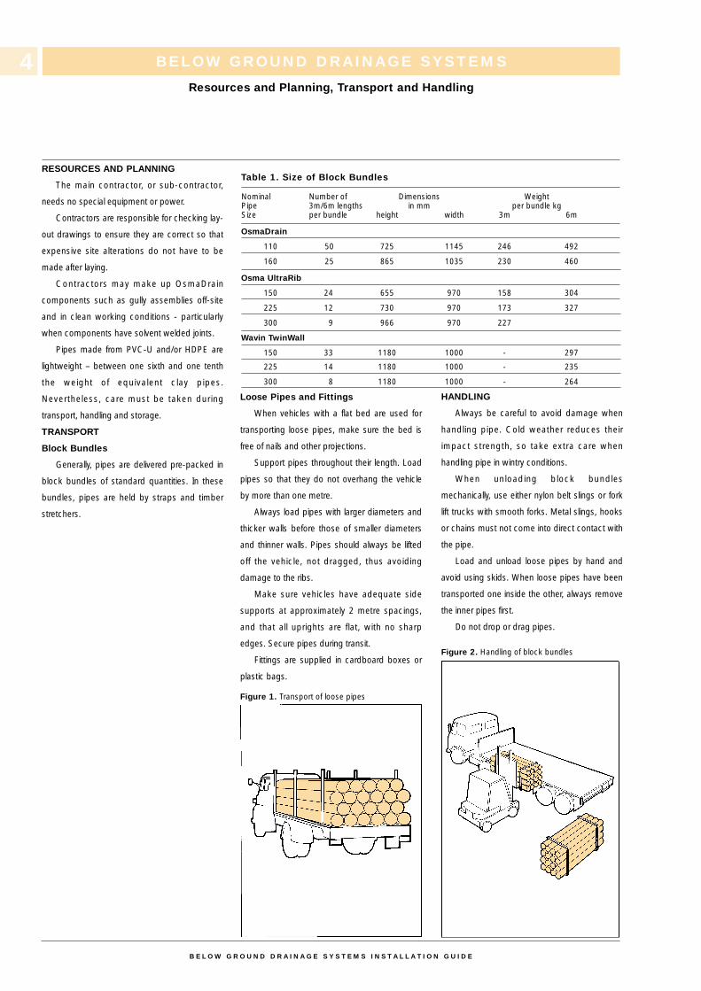
Table 1. Size of Block Bundles
Nominal Number of Dimensions WeightPipe 3m/6m lengths in mm per bundle kgSize per bundle height width 3m 6m
OsmaDrain
110 50 725 1145 246 492
160 25 865 1035 230 460
Osma UltraRib
150 24 655 970 158 304
225 12 730 970 173 327
300 9 966 970 227
Wavin TwinWall
150 33 1180 1000 - 297
225 14 1180 1000 - 235
300 8 1180 1000 - 264
RESOURCES AND PLANNING
The main contractor, or sub-contractor,
needs no special equipment or power.
Contractors are responsible for checking lay-
out drawings to ensure they are correct so that
expensive site alterations do not have to be
made after laying.
Contractors may make up OsmaDrain
components such as gully assemblies off-site
and in clean working conditions - particularly
when components have solvent welded joints.
Pipes made from PVC-U and/or HDPE are
lightweight – between one sixth and one tenth
the weight of equivalent clay pipes.
Nevertheless, care must be taken during
transport, handling and storage.
TRANSPORT
Block Bundles
Generally, pipes are delivered pre-packed in
block bundles of standard quantities. In these
bundles, pipes are held by straps and timber
stretchers.
Loose Pipes and Fittings
When vehicles with a flat bed are used for
transporting loose pipes, make sure the bed is
free of nails and other projections.
Support pipes throughout their length. Load
pipes so that they do not overhang the vehicle
by more than one metre.
Always load pipes with larger diameters and
thicker walls before those of smaller diameters
and thinner walls. Pipes should always be lifted
off the vehicle, not dragged, thus avoiding
damage to the ribs.
Make sure vehicles have adequate side
supports at approximately 2 metre spacings,
and that all uprights are flat, with no sharp
edges. Secure pipes during transit.
Fittings are supplied in cardboard boxes or
plastic bags.
Figure 1. Transport of loose pipes
HANDLING
Always be careful to avoid damage when
handling pipe. Cold weather reduces their
impact strength, so take extra care when
handling pipe in wintry conditions.
When unloading block bundles
mechanically, use either nylon belt slings or fork
lift trucks with smooth forks. Metal slings, hooks
or chains must not come into direct contact with
the pipe.
Load and unload loose pipes by hand and
avoid using skids. When loose pipes have been
transported one inside the other, always remove
the inner pipes first.
Do not drop or drag pipes.
Figure 2. Handling of block bundles
BELOW GROUND DRAINAGE SYSTEMS
Resources and Planning, Transport and Handling
4
B E L O W G R O U N D D R A I N A G E S Y S T E M S I N S T A L L A T I O N G U I D E
BELOW GROUND DRAINAGE SYSTEMS
Storage
STORAGE
Block Bundles
Store block bundles on a reasonably flat
surface free from sharp projections likely to
damage the pipes.
Block bundles can be stored up to three
high without extra side supports or bearers. In
addition, block bundles will remain free standing
when cut.
Take care when removing pipes from
bundles as the straps are under considerable
tension and may flail when cut.
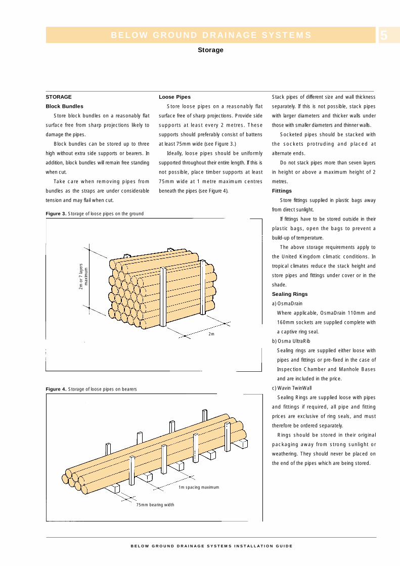
Figure 3. Storage of loose pipes on the ground
Figure 4. Storage of loose pipes on bearers
Loose Pipes
Store loose pipes on a reasonably flat
surface free of sharp projections. Provide side
supports at least every 2 metres. These
supports should preferably consist of battens
at least 75mm wide (see Figure 3.)
Ideally, loose pipes should be uniformly
supported throughout their entire length. If this is
not possible, place timber supports at least
75mm wide at 1 metre maximum centres
beneath the pipes (see Figure 4).
Stack pipes of different size and wall thickness
separately. If this is not possible, stack pipes
with larger diameters and thicker walls under
those with smaller diameters and thinner walls.
Socketed pipes should be stacked with
the sockets protruding and placed at
alternate ends.
Do not stack pipes more than seven layers
in height or above a maximum height of 2
metres.
Fittings
Store fittings supplied in plastic bags away
from direct sunlight.
If fittings have to be stored outside in their
plastic bags, open the bags to prevent a
build-up of temperature.
The above storage requirements apply to
the United Kingdom climatic conditions. In
tropical climates reduce the stack height and
store pipes and fittings under cover or in the
shade.
Sealing Rings
a) OsmaDrain
Where applicable, OsmaDrain 110mm and
160mm sockets are supplied complete with
a captive ring seal.
b) Osma UltraRib
Sealing rings are supplied either loose with
pipes and fittings or pre-fixed in the case of
Inspection Chamber and Manhole Bases
and are included in the price.
c) Wavin TwinWall
Sealing Rings are supplied loose with pipes
and fittings if required, all pipe and fitting
prices are exclusive of ring seals, and must
therefore be ordered separately.
Rings should be stored in their original
packaging away from strong sunlight or
weathering. They should never be placed on
the end of the pipes which are being stored.
5
B E L O W G R O U N D D R A I N A G E S Y S T E M S I N S T A L L A T I O N G U I D E
2m
2m o
r 7
laye
rs
max
imum
1m spacing maximum
75mm bearing width
INSTALLATION NOTES
The information included on this page is
based on the recommendations given in BS
5955: Part 6: 1980 ‘Code of Practice for Plastics
Pipework’ (Installation of unplasticized PVC
pipework for gravity drains and sewers), BS
8301: 1985 Code of Practice for Building
Drainage, Water Industry Specification (WIS), No
4-08-02 (Specification for bedding and sidefill
Materials for buried Pipelines) and British Board
of Agrément Certificate Nos 87/1835: 89/46,
89/2268, 90/2563 and 91/58.
Bedding and backfill must be of the correct
specification. Excavated ‘as-dug’ material may
be suitable (see BS 5955: Part 6: 1980 for ‘as-
dug’ suitability tests), otherwise a non-cohesive
material is required (see Table 2).
EXCAVATION
It is important to take precautions against
trench collapse. Do not open trenches too far in
advance of pipe laying. Support the sides of
trenches that are deeper than 1.2 metres. Keep
trench widths as narrow as practicable but not
less than 300mm wider than the pipe diameter,
i.e. 150mm clear each side of the pipe to allow
proper compaction of the sidefill.
Excavation for Manholes andInspection Chambers
Additional excavation is necessary for:
a. Traditionally constructed manholes.
b. OsmaDrain/Osma UltraRib 750mm
Manhole Bases
OsmaDrain and Osma UltraRib 250mm /
300mm / 450mm diameter Shallow / Multi-Base /
Universal Inspection Chambers need no
additional excavation other than that required for
normal drain laying.
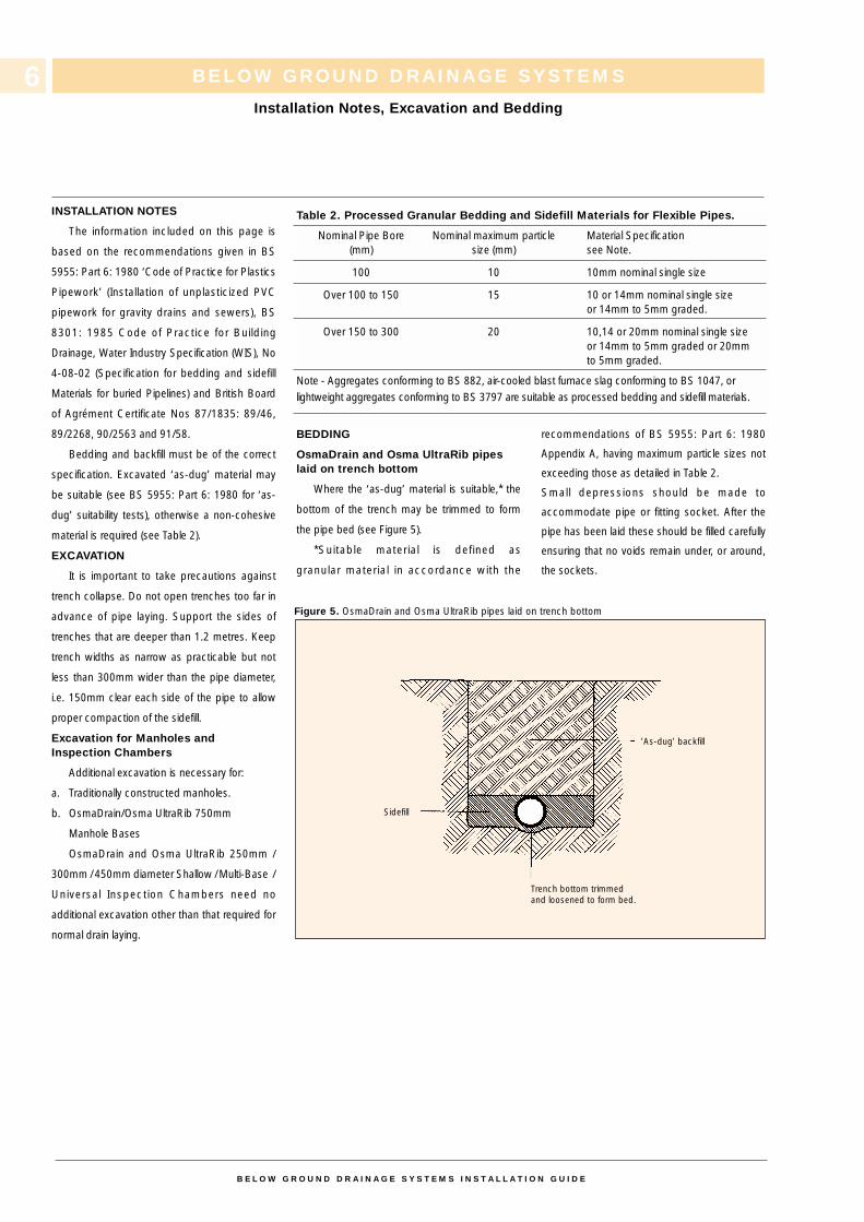
BEDDING
OsmaDrain and Osma UltraRib pipeslaid on trench bottom
Where the ‘as-dug’ material is suitable,* the
bottom of the trench may be trimmed to form
the pipe bed (see Figure 5).
*Suitable material is defined as
granular material in accordance with the
recommendations of BS 5955: Part 6: 1980
Appendix A, having maximum particle sizes not
exceeding those as detailed in Table 2.
Small depressions should be made to
accommodate pipe or fitting socket. After the
pipe has been laid these should be filled carefully
ensuring that no voids remain under, or around,
the sockets.
Figure 5. OsmaDrain and Osma UltraRib pipes laid on trench bottom
BELOW GROUND DRAINAGE SYSTEMS
Installation Notes, Excavation and Bedding
B E L O W G R O U N D D R A I N A G E S Y S T E M S I N S T A L L A T I O N G U I D E
6
Table 2. Processed Granular Bedding and Sidefill Materials for Flexible Pipes.
Nominal Pipe Bore Nominal maximum particle Material Specification(mm) size (mm) see Note.
100 10 10mm nominal single size
Over 100 to 150 15 10 or 14mm nominal single sizeor 14mm to 5mm graded.
Over 150 to 300 20 10,14 or 20mm nominal single sizeor 14mm to 5mm graded or 20mmto 5mm graded.
Note - Aggregates conforming to BS 882, air-cooled blast furnace slag conforming to BS 1047, orlightweight aggregates conforming to BS 3797 are suitable as processed bedding and sidefill materials.
Sidefill
’As-dug’ backfill
Trench bottom trimmed and loosened to form bed.
BELOW GROUND DRAINAGE SYSTEMS
Bedding continued
When the formation is prepared, the pipes
should be laid upon it true to line and level within
the specified tolerances. Each pipe should be
checked and any necessary adjustments to
level made by raising or lowering the formation,
ensuring that the pipes finally rest evenly on the
adjusted formation throughout the length of the
barrels. Adjustment should never be made by
local packing. When the formation is low and
does not provide continuous support, it should
be brought up to the correct level by placing
and compacting suitable material.
OsmaDrain and Osma UltraRib pipeslaid on processed granular bedding
When the ‘as-dug’ material is not suitable, a
layer of suitable processed granular material
must be spread evenly on the trimmed trench
bottom. The trench should be excavated to
allow for the thickness of granular bedding
under the barrels. The trench formation should
be prepared, the bedding placed and the pipes
laid in accordance with BS 5955: Part 6: 1980
and BS 8301: 1985.
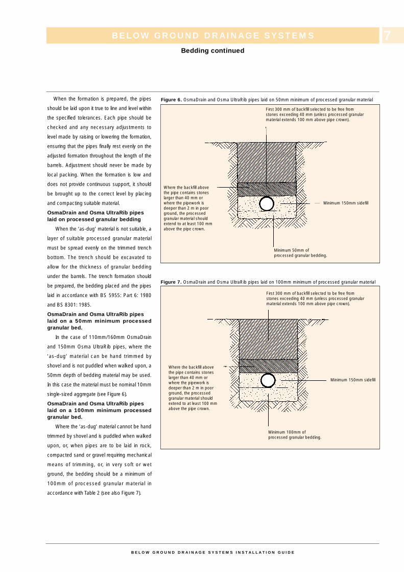
OsmaDrain and Osma UltraRib pipeslaid on a 50mm minimum processedgranular bed.
In the case of 110mm/160mm OsmaDrain
and 150mm Osma UltraRib pipes, where the
‘as-dug’ material can be hand trimmed by
shovel and is not puddled when walked upon, a
50mm depth of bedding material may be used.
In this case the material must be nominal 10mm
single-sized aggregate (see Figure 6).
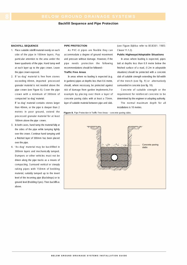
OsmaDrain and Osma UltraRib pipeslaid on a 100mm minimum processedgranular bed.
Where the ‘as-dug’ material cannot be hand
trimmed by shovel and is puddled when walked
upon, or, when pipes are to be laid in rock,
compacted sand or gravel requiring mechanical
means of trimming, or, in very soft or wet
ground, the bedding should be a minimum of
100mm of processed granular material in
accordance with Table 2 (see also Figure 7).
B E L O W G R O U N D D R A I N A G E S Y S T E M S I N S T A L L A T I O N G U I D E
7
Figure 6. OsmaDrain and Osma UltraRib pipes laid on 50mm minimum of processed granular material
Figure 7. OsmaDrain and Osma UltraRib pipes laid on 100mm minimum of processed granular material
First 300 mm of backfill selected to be free fromstones exceeding 40 mm (unless processed granularmaterial extends 100 mm above pipe crown).
First 300 mm of backfill selected to be free fromstones exceeding 40 mm (unless processed granularmaterial extends 100 mm above pipe crown).
Minimum 150mm sidefill
Minimum 150mm sidefill
Minimum 100mm of processed granular bedding.
Minimum 50mm of processed granular bedding.
Where the backfill abovethe pipe contains stoneslarger than 40 mm orwhere the pipework isdeeper than 2 m in poorground, the processedgranular material shouldextend to at least 100 mmabove the pipe crown.
Where the backfill abovethe pipe contains stoneslarger than 40 mm orwhere the pipework isdeeper than 2 m in poorground, the processedgranular material shouldextend to at least 100 mmabove the pipe crown.
BELOW GROUND DRAINAGE SYSTEMS
Backfill Sequence and Pipe Protection
BACKFILL SEQUENCE
1. Place suitable sidefill material evenly on each
side of the pipe in 100mm layers. Pay
particular attention to the area under the
lower quadrants of the pipe. Hand tamp well
at each layer up to the pipe crown. Leave
the pipe crown exposed.
2. If ‘as-dug’ material is free from stones
exceeding 40mm, imported processed
granular material is not needed above the
pipe crown (see Figure 6). Cover the pipe
crown with a minimum of 300mm of
compacted ‘as-dug’ material.
If ‘as-dug’ material contains stones larger
than 40mm, or the pipe is deeper than 2
metres in poor ground, extend the
processed granular material for at least
100mm above the pipe crown.
3. In both cases, hand tamp the material fully at
the sides of the pipe while tamping lightly
over the crown. Continue hand tamping until
a finished layer of 300mm has been placed
over the pipe.
4. ‘As-dug’ material may be backfilled in
300mm layers and mechanically tamped.
Dumpers or other vehicles must not be
driven along the pipe tracks as a means of
compacting. Surround vertical or steeply
raking pipes with 150mm of bedding
material, suitably tamped up to the invert
level of the incoming pipe (Backdrops) or to
ground level (Rodding Eyes). Then backfill as
above.
PIPE PROTECTION
As PVC-U pipes are flexible they can
accommodate a degree of ground movement
and pressure without damage. However, if the
pipe needs protection the following
recommendations should be followed:-
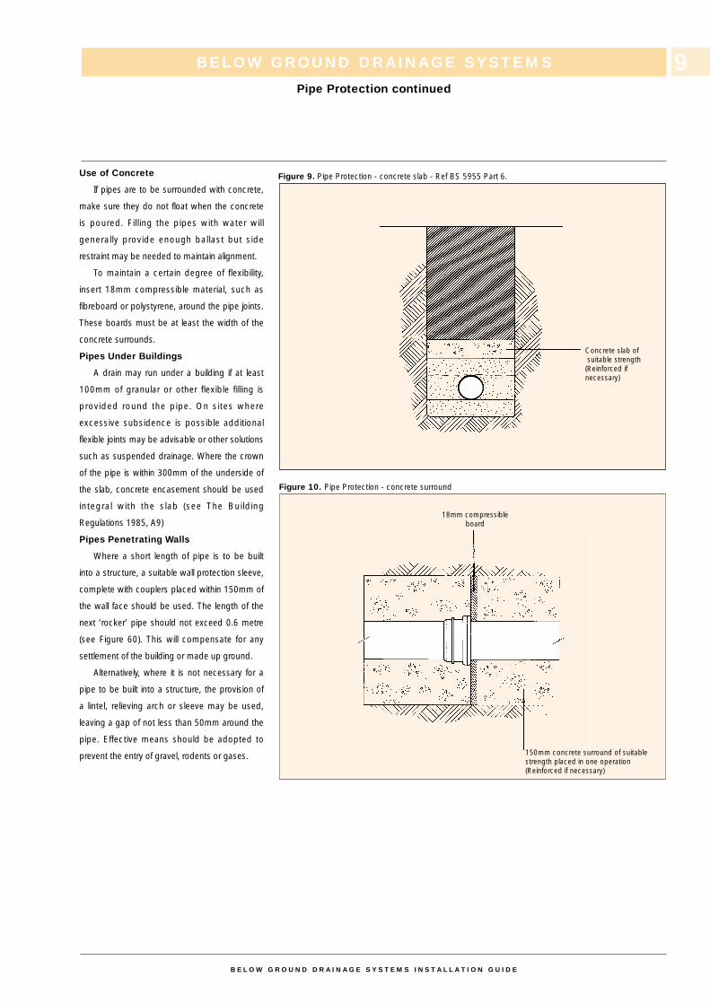
Traffic Free Areas
In areas where no loading is expected (e.g.
in gardens) pipes at depths less than 0.6 metre,
should, where necessary, be protected against
risk of damage from garden implements,For
example by placing over them a layer of
concrete paving slabs with at least a 75mm.
layer of suitable material between pipe and slab.
(see Figure 8)(Also refer to BS8301: 1985:
Clause 11.1.2).
Public Highways/Adoptable Situations
In areas where loading is expected, pipes
laid at depths less than 0.9 metre below the
finished surface of a road, (1.2m in adoptable
situations) should be protected with a concrete
slab of suitable strength extending the full width
of the trench (see fig. 9) or alternatively
surrounded in concrete (see fig. 10).
Concrete of suitable strength or the
requirement for reinforced concrete to be
determined by the engineer or adopting authority.
The normal maximum depth for all
installations is 10 metres.
B E L O W G R O U N D D R A I N A G E S Y S T E M S I N S T A L L A T I O N G U I D E
8
Figure 8. Pipe Protection in Traffic Free Areas - concrete paving slabs.
Concrete pavingslabs
Use of Concrete
If pipes are to be surrounded with concrete,
make sure they do not float when the concrete
is poured. Filling the pipes with water will
generally provide enough ballast but side
restraint may be needed to maintain alignment.
To maintain a certain degree of flexibility,
insert 18mm compressible material, such as
fibreboard or polystyrene, around the pipe joints.
These boards must be at least the width of the
concrete surrounds.
Pipes Under Buildings
A drain may run under a building if at least
100mm of granular or other flexible filling is
provided round the pipe. On sites where
excessive subsidence is possible additional
flexible joints may be advisable or other solutions
such as suspended drainage. Where the crown
of the pipe is within 300mm of the underside of
the slab, concrete encasement should be used
integral with the slab (see The Building
Regulations 1985, A9)
Pipes Penetrating Walls
Where a short length of pipe is to be built
into a structure, a suitable wall protection sleeve,
complete with couplers placed within 150mm of
the wall face should be used. The length of the
next ‘rocker’ pipe should not exceed 0.6 metre
(see Figure 60). This will compensate for any
settlement of the building or made up ground.
Alternatively, where it is not necessary for a
pipe to be built into a structure, the provision of
a lintel, relieving arch or sleeve may be used,
leaving a gap of not less than 50mm around the
pipe. Effective means should be adopted to
prevent the entry of gravel, rodents or gases.
BELOW GROUND DRAINAGE SYSTEMS
Pipe Protection continued
B E L O W G R O U N D D R A I N A G E S Y S T E M S I N S T A L L A T I O N G U I D E
9
Figure 10. Pipe Protection - concrete surround
Concrete slab ofsuitable strength(Reinforced if necessary)
18mm compressible board
150mm concrete surround of suitablestrength placed in one operation(Reinforced if necessary)
Figure 9. Pipe Protection - concrete slab - Ref BS 5955 Part 6.
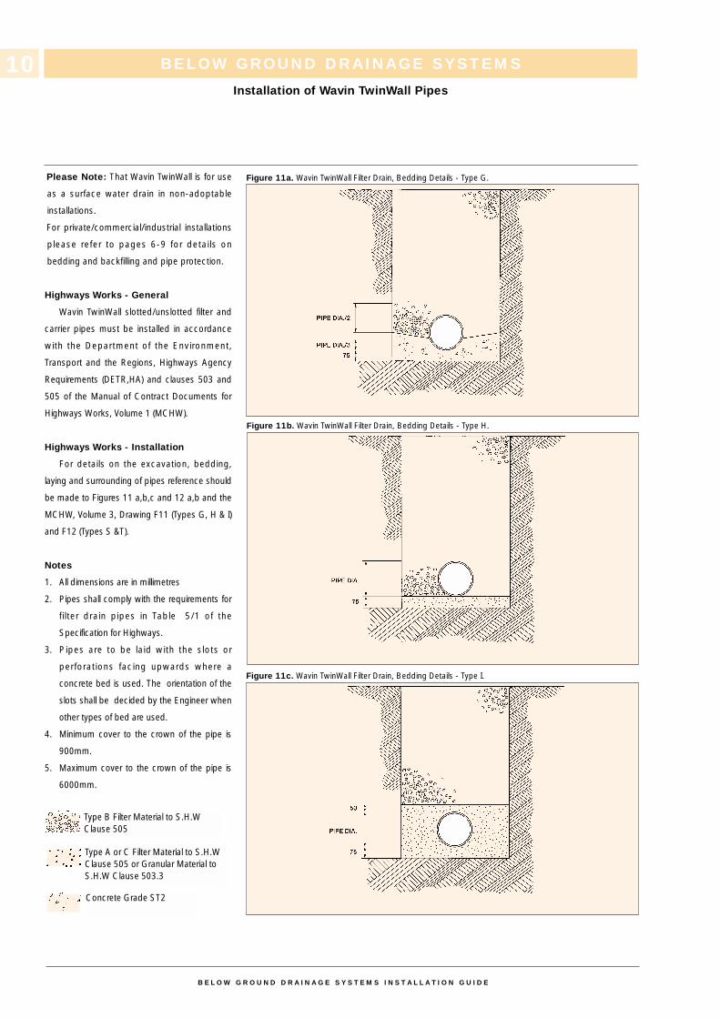
Please Note: That Wavin TwinWall is for use
as a surface water drain in non-adoptable
installations.
For private/commercial/industrial installations
please refer to pages 6-9 for details on
bedding and backfilling and pipe protection.
Highways Works - General
Wavin TwinWall slotted/unslotted filter and
carrier pipes must be installed in accordance
with the Department of the Environment,
Transport and the Regions, Highways Agency
Requirements (DETR,HA) and clauses 503 and
505 of the Manual of Contract Documents for
Highways Works, Volume 1 (MCHW).
Highways Works - Installation
For details on the excavation, bedding,
laying and surrounding of pipes reference should
be made to Figures 11 a,b,c and 12 a,b and the
MCHW, Volume 3, Drawing F11 (Types G, H & I)
and F12 (Types S &T).
Notes
1. All dimensions are in millimetres
2. Pipes shall comply with the requirements for
filter drain pipes in Table 5/1 of the
Specification for Highways.
3. Pipes are to be laid with the slots or
perforations facing upwards where a
concrete bed is used. The orientation of the
slots shall be decided by the Engineer when
other types of bed are used.
4. Minimum cover to the crown of the pipe is
900mm.
5. Maximum cover to the crown of the pipe is
6000mm.
BELOW GROUND DRAINAGE SYSTEMS
Installation of Wavin TwinWall Pipes
B E L O W G R O U N D D R A I N A G E S Y S T E M S I N S T A L L A T I O N G U I D E
10
Concrete Grade ST2
Type A or C Filter Material to S.H.WClause 505 or Granular Material toS.H.W Clause 503.3
Type B Filter Material to S.H.WClause 505
Figure 11a. Wavin TwinWall Filter Drain, Bedding Details - Type G.
Figure 11b. Wavin TwinWall Filter Drain, Bedding Details - Type H.
Figure 11c. Wavin TwinWall Filter Drain, Bedding Details - Type I.
BELOW GROUND DRAINAGE SYSTEMS
Installation of Wavin TwinWall Pipes
B E L O W G R O U N D D R A I N A G E S Y S T E M S I N S T A L L A T I O N G U I D E
11
Table 3. Wavin TwinWall Bedding - Highway Drainage. Table 5/3 Granular Materials to BS 882
BS 882 Coarse Aggregate (Table 4)
Pipe Diameter(mm)
Graded Aggregate Single Sized AggregateRanges (mm) Sizes (mm)
Not Exceeding 140 - 10
Exceeding 140 butnot exceeding 400 20 to 5 or 14 to 5 10, 14 or 20
Exceeding 400 14 to 5, 20 to 5 10, 14, 20 or 40or 40 to 5
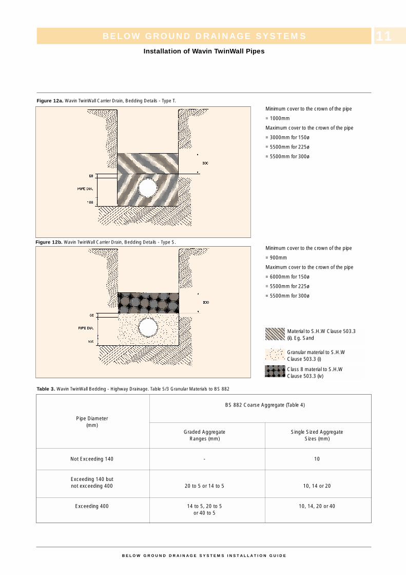
Figure 12a. Wavin TwinWall Carrier Drain, Bedding Details - Type T.
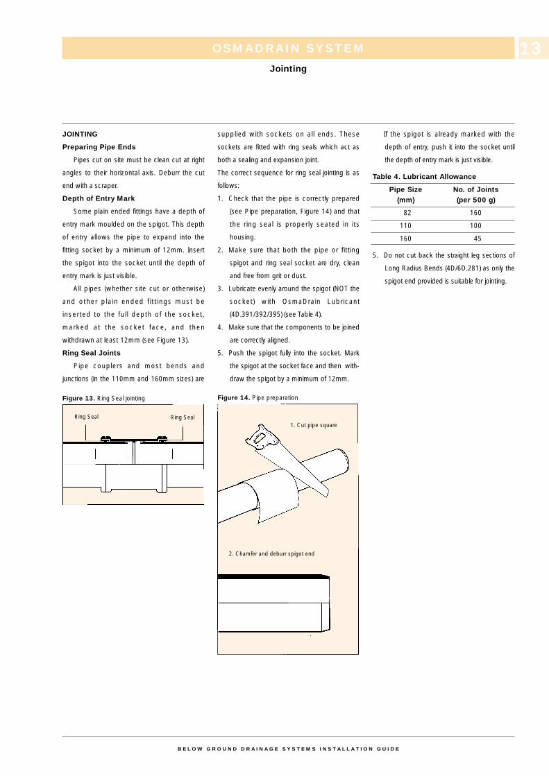
Material to S.H.W Clause 503.3(ii). Eg. Sand
Granular material to S.H.WClause 503.3 (i)
Class 8 material to S.H.WClause 503.3 (iv)
Minimum cover to the crown of the pipe
= 1000mm
Maximum cover to the crown of the pipe
= 3000mm for 150ø
= 5500mm for 225ø
= 5500mm for 300ø
Minimum cover to the crown of the pipe
= 900mm
Maximum cover to the crown of the pipe
= 6000mm for 150ø
= 5500mm for 225ø
= 5500mm for 300ø
Figure 12b. Wavin TwinWall Carrier Drain, Bedding Details - Type S.

CONTENTS PAGE
Jointing 13-14
Vertical Connections 15-17
Access to Drains 18
Shallow Inspection Chamber 18
Multi-Base Inspection Chambers 19
Universal Inspection Chambers 20-21
Manhole Bases 22
Sealed Access Fittings 23
Backdrops 24
Sealed Rodding Access Fittings 25
Manhole Construction 26
Channel Fittings 26-27
Universal Gully 28
Bottle Gully 29
Yard Gully 30
Connections to other Materials 31
Slotted Rigid Pipe 32
Subsoil Drainage Pipe 33
Wall Protection Sleeve 33
Maintenance 34
Access for Cleaning 34
OSMADRAIN SYSTEM
Contents
12
B E L O W G R O U N D D R A I N A G E S Y S T E M S I N S T A L L A T I O N G U I D E
JOINTING
Preparing Pipe Ends
Pipes cut on site must be clean cut at right
angles to their horizontal axis. Deburr the cut
end with a scraper.
Depth of Entry Mark
Some plain ended fittings have a depth of
entry mark moulded on the spigot. This depth
of entry allows the pipe to expand into the
fitting socket by a minimum of 12mm. Insert
the spigot into the socket until the depth of
entry mark is just visible.
All pipes (whether site cut or otherwise)
and other plain ended f itt ings must be
inserted to the full depth of the socket,
marked at the socket face, and then
withdrawn at least 12mm (see Figure 13).
Ring Seal Joints
Pipe couplers and most bends and
junctions (in the 110mm and 160mm sizes) are
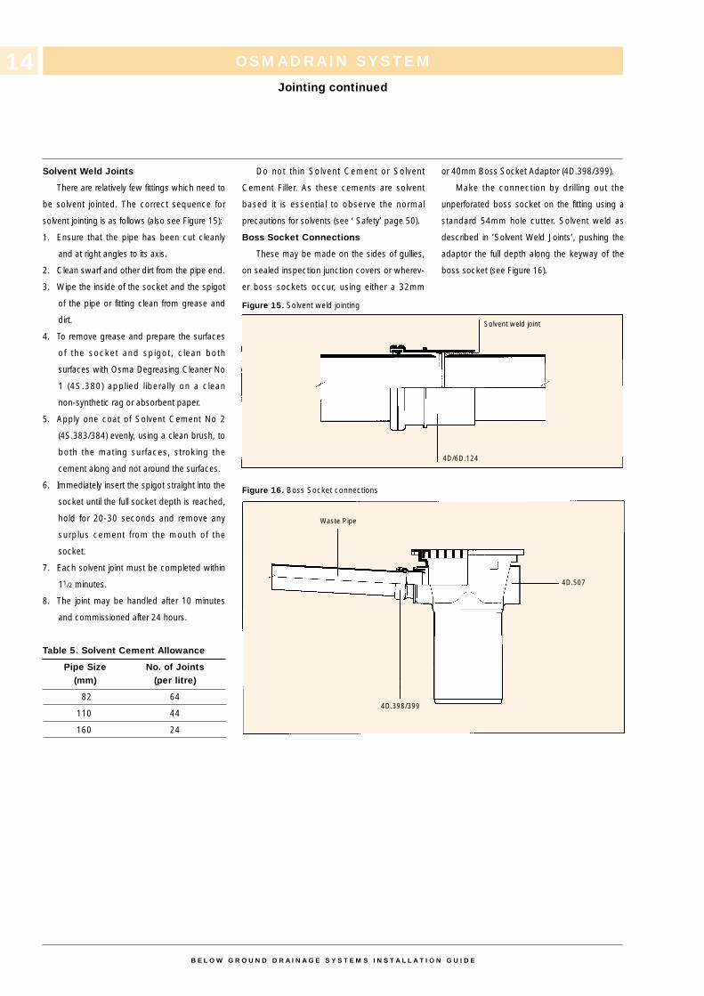
Figure 13. Ring Seal jointing
supplied with sockets on all ends. These
sockets are fitted with ring seals which act as
both a sealing and expansion joint.
The correct sequence for ring seal jointing is as
follows:
1. Check that the pipe is correctly prepared
(see Pipe preparation, Figure 14) and that
the ring seal is properly seated in its
housing.
2. Make sure that both the pipe or fitting
spigot and ring seal socket are dry, clean
and free from grit or dust.
3. Lubricate evenly around the spigot (NOT the
socket) with OsmaDrain Lubricant
(4D.391/392/395) (see Table 4).
4. Make sure that the components to be joined
are correctly aligned.
5. Push the spigot fully into the socket. Mark
the spigot at the socket face and then with-
draw the spigot by a minimum of 12mm.
Figure 14. Pipe preparation
If the spigot is already marked with the
depth of entry, push it into the socket until
the depth of entry mark is just visible.
Table 4. Lubricant Allowance
Pipe Size No. of Joints(mm) (per 500 g)
82 160
110 100
160 45
5. Do not cut back the straight leg sections of
Long Radius Bends (4D/6D.281) as only the
spigot end provided is suitable for jointing.
OSMADRAIN SYSTEM
Jointing
13
B E L O W G R O U N D D R A I N A G E S Y S T E M S I N S T A L L A T I O N G U I D E
Ring Seal Ring Seal1. Cut pipe square
2. Chamfer and deburr spigot end
Solvent Weld Joints
There are relatively few fittings which need to
be solvent jointed. The correct sequence for
solvent jointing is as follows (also see Figure 15):
1. Ensure that the pipe has been cut cleanly
and at right angles to its axis.
2. Clean swarf and other dirt from the pipe end.
3. Wipe the inside of the socket and the spigot
of the pipe or fitting clean from grease and
dirt.
4. To remove grease and prepare the surfaces
of the socket and spigot, clean both
surfaces with Osma Degreasing Cleaner No
1 (4S.380) applied liberally on a clean
non-synthetic rag or absorbent paper.
5. Apply one coat of Solvent Cement No 2
(4S.383/384) evenly, using a clean brush, to
both the mating surfaces, stroking the
cement along and not around the surfaces.
6. Immediately insert the spigot straight into the
socket until the full socket depth is reached,
hold for 20-30 seconds and remove any
surplus cement from the mouth of the
socket.
7. Each solvent joint must be completed within
11/2 minutes.
8. The joint may be handled after 10 minutes
and commissioned after 24 hours.
Table 5. Solvent Cement Allowance
Pipe Size No. of Joints(mm) (per litre)
82 64
110 44
160 24
Do not thin Solvent Cement or Solvent
Cement Filler. As these cements are solvent
based it is essential to observe the normal
precautions for solvents (see ‘ Safety’ page 50).
Boss Socket Connections
These may be made on the sides of gullies,
on sealed inspection junction covers or wherev-
er boss sockets occur, using either a 32mm
Figure 15. Solvent weld jointing
Figure 16. Boss Socket connections
or 40mm Boss Socket Adaptor (4D.398/399).
Make the connection by drilling out the
unperforated boss socket on the fitting using a
standard 54mm hole cutter. Solvent weld as
described in ’Solvent Weld Joints’, pushing the
adaptor the full depth along the keyway of the
boss socket (see Figure 16).
OSMADRAIN SYSTEM
Jointing continued
14
B E L O W G R O U N D D R A I N A G E S Y S T E M S I N S T A L L A T I O N G U I D E
Solvent weld joint
Waste Pipe
4D/6D.124
4D.507
4D.398/399
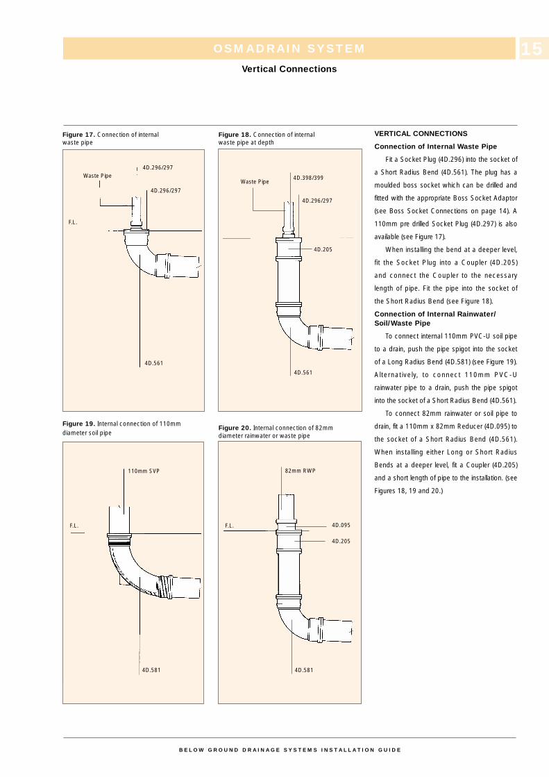
Figure 17. Connection of internalwaste pipe
Figure 19. Internal connection of 110mmdiameter soil pipe
Figure 18. Connection of internalwaste pipe at depth
Figure 20. Internal connection of 82mmdiameter rainwater or waste pipe
VERTICAL CONNECTIONS
Connection of Internal Waste Pipe
Fit a Socket Plug (4D.296) into the socket of
a Short Radius Bend (4D.561). The plug has a
moulded boss socket which can be drilled and
fitted with the appropriate Boss Socket Adaptor
(see Boss Socket Connections on page 14). A
110mm pre drilled Socket Plug (4D.297) is also
available (see Figure 17).
When installing the bend at a deeper level,
fit the Socket Plug into a Coupler (4D.205)
and connect the Coupler to the necessary
length of pipe. Fit the pipe into the socket of
the Short Radius Bend (see Figure 18).
Connection of Internal Rainwater/Soil/Waste Pipe
To connect internal 110mm PVC-U soil pipe
to a drain, push the pipe spigot into the socket
of a Long Radius Bend (4D.581) (see Figure 19).
Alternatively, to connect 110mm PVC-U
rainwater pipe to a drain, push the pipe spigot
into the socket of a Short Radius Bend (4D.561).
To connect 82mm rainwater or soil pipe to
drain, fit a 110mm x 82mm Reducer (4D.095) to
the socket of a Short Radius Bend (4D.561).
When installing either Long or Short Radius
Bends at a deeper level, fit a Coupler (4D.205)
and a short length of pipe to the installation. (see
Figures 18, 19 and 20.)
OSMADRAIN SYSTEM
Vertical Connections
15
B E L O W G R O U N D D R A I N A G E S Y S T E M S I N S T A L L A T I O N G U I D E
4D.296/297
Waste Pipe
F.L.
4D.561
4D.581
F.L.
4D.581
110mm SVP
Waste Pipe4D.398/399
4D.296/297
4D.205
4D.561
82mm RWP
4D.095
4D.205
F.L.
4D.296/297
OSMADRAIN SYSTEM
Vertical Connections continued
16
B E L O W G R O U N D D R A I N A G E S Y S T E M S I N S T A L L A T I O N G U I D E
68mm OsmaRoundLinePipe
G.L.
4D.149
4D.561 4D.561
4D.149
G.L.
68mm OsmaRoundLinePipe
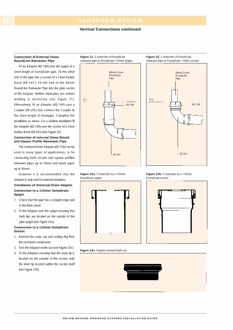
Connection of External OsmaRoundLine Rainwater Pipe
Fit an Adaptor (4D.149) over the spigot of a
short length of OsmaDrain pipe. Fit the other
end of the pipe into a socket of a Short Radius
Bend (4D.561). Fit the end of the 68mm
RoundLine Rainwater Pipe into the plain socket
of the Adaptor. Neither lubrication nor solvent
welding is necessary (see Figure 21).
Alternatively, fit an Adaptor (4D.149) over a
Coupler (4D.205) and connect the Coupler to
the short length of drainpipe. Complete the
installation as above. For a shallow installation fit
the Adaptor (4D.149) over the socket of a Short
Radius Bend (4D.561) (see Figure 22).
Connection of external Osma Round and Square Profile Rainwater Pipe
The Universal Drain Adaptor (4D.159) can be
used in many types of applications, ie for
connecting both circular and square profiled
rainwater pipes up to 70mm and waste pipes
up to 50mm.
However it is recommended that the
Adaptor is only used in external situations.
Installation of Universal Drain Adaptor
Connection to a 110mm OsmaDrain Spigot.
1. Check that the pipe has a straight edge and
is free from swarf.
2. Fit the Adaptor over the spigot ensuring that
both lips are located on the outside of the
pipe spigot (see Figure 23a).
Connection to a 110mm OsmaDrain Socket.
1. Remove the snap cap and sealing ring from
the socketed component.
2. Turn the Adaptor inside out (see Figure 23c).
3. Fit the Adaptor, ensuring that the outer lip is
located on the outside of the socket, with
the inner lip located within the socket itself
(see Figure 23b).
Figure 21. Connection of RoundLinerainwater pipe to OsmaDrain 110mm spigot.
Figure 23a. Connection to a 110mmOsmaDrain spigot
Figure 23c. Adaptor turned inside out
Figure 22. Connection of RoundLinerainwater pipe to OsmaDrain 110mm socket
Figure 23b. Connection to a 110mmOsmaDrain socket
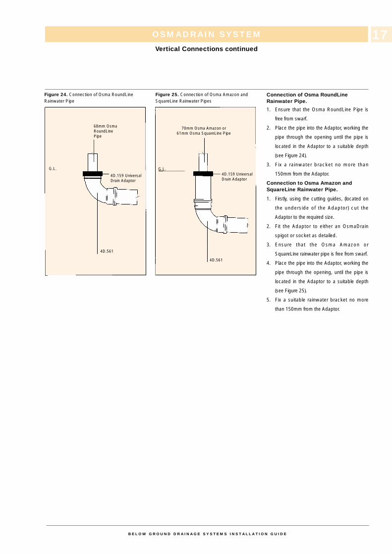
Figure 24. Connection of Osma RoundLineRainwater Pipe
Figure 25. Connection of Osma Amazon andSquareLine Rainwater Pipes
Connection of Osma RoundLine Rainwater Pipe.
1. Ensure that the Osma RoundLine Pipe is
free from swarf.
2. Place the pipe into the Adaptor, working the
pipe through the opening until the pipe is
located in the Adaptor to a suitable depth
(see Figure 24).
3. Fix a rainwater bracket no more than
150mm from the Adaptor.
Connection to Osma Amazon and SquareLine Rainwater Pipe.
1. Firstly, using the cutting guides, (located on
the underside of the Adaptor) cut the
Adaptor to the required size.
2. Fit the Adaptor to either an OsmaDrain
spigot or socket as detailed.
3. Ensure that the Osma Amazon or
SquareLine rainwater pipe is free from swarf.
4. Place the pipe into the Adaptor, working the
pipe through the opening, until the pipe is
located in the Adaptor to a suitable depth
(see Figure 25).
5. Fix a suitable rainwater bracket no more
than 150mm from the Adaptor.
OSMADRAIN SYSTEM
Vertical Connections continued
B E L O W G R O U N D D R A I N A G E S Y S T E M S I N S T A L L A T I O N G U I D E
17
68mm OsmaRoundLinePipe
70mm Osma Amazon or61mm Osma SquareLine Pipe
G.L.
4D.561
4D.159 UniversalDrain Adaptor
G.L.
4D.561
4D.159 UniversalDrain Adaptor
ACCESS TO DRAINS
The OsmaDrain range offers many different
types of component for gaining access to
drains: Shallow/Multi-Base Inspection
Chambers, Universal Inspection Chambers,
Sealed Rodding Access Fittings, Manhole
Bases, and within traditional manholes, Channel
and Sealed Access Fittings.
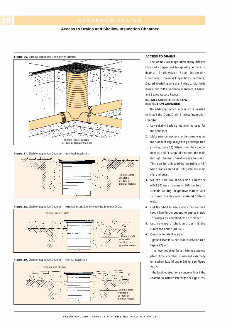
INSTALLATION OF SHALLOW INSPECTION CHAMBER
No additional trench excavation is needed
to install the OsmaDrain Shallow Inspection
Chamber.
1. Lay suitable bedding material (as used for
the drain line).
2. Make pipe connections in the same way as
the standard ring seal jointing of fittings (see
Jointing, page 13). When using the compo-
nent as a 90˚ change of direction, the main
through channel should always be used.
This can be achieved by inserting a 45˚Short Radius Bend (4D.163) into the main
inlet and outlet.
3. Sit the Shallow Inspection Chamber
(4D.960) on a minimum 100mm bed of
suitable ’as-dug’ or granular material and
surround it with similar material 150mm
wide.
4. Cut the Shaft to size using a fine toothed
saw. Chamfer the cut end to approximately
15˚ using a plain toothed rasp or scraper.
5. Lubricate top of shaft, and push-fit’ the
Cover and Frame (4D.961).
6. Continue to sidefill to either:
- ground level for a non-load installation (see
Figure 27), or
- the level required for a 150mm concrete
plinth if the chamber is installed externally
for a wheel load of under 250kg (see Figure
28), or
- the level required for a concrete floor if the
chamber is installed internally (see Figure 29).
OSMADRAIN SYSTEM
Access to Drains and Shallow Inspection Chamber
Figure 26. Shallow Inspection Chamber installation
Figure 27. Shallow Inspection Chamber – non-load installation
Figure 28. Shallow Inspection Chamber – external installation for wheel loads under 250kg
Figure 29. Shallow Inspection Chamber – internal installation
B E L O W G R O U N D D R A I N A G E S Y S T E M S I N S T A L L A T I O N G U I D E
18
150mm Sidefill of suitable ‘as-dug’ or granular material
150mm Sidefill of suitable ‘as-dug’ or granular material
Concrete and tile floor
150mm Sidefill of suitable ‘as-dug’ or granular material
100mm bed of suitable ‘as-dug’ or granular material
150mm concrete plinth
OSMADRAIN SYSTEM
Multi-Base Shallow Inspection Chambers
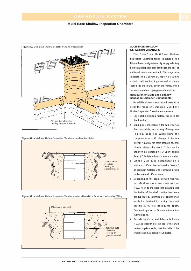
Figure 30. Multi-Base Shallow Inspection Chamber installation
Figure 31. Multi-Base Shallow Inspection Chamber – non load installation
Figure 32. Multi-Base Shallow Inspection Chamber – external installation for wheel loads under 250kg
B E L O W G R O U N D D R A I N A G E S Y S T E M S I N S T A L L A T I O N G U I D E
19
100mm bed of suitable ‘as-dug’ or granular material
150mm Sidefill of suitable ‘as-dug’ or granular material
150mm concrete plinth
150mm Sidefill of suitable ‘as-dug’ or granular material
MULTI-BASE SHALLOWINSPECTION CHAMBERS
The OsmaDrain Multi-Base Shallow
Inspection Chamber range consists of ten
different base configurations. By simply selecting
the most appropriate base for the job the cost of
additional bends are avoided. The range also
consists of a 300mm diameter x 150mm
push-fit shaft section, together with a square
section, tilt and rotate, cover and frame, which
can accommodate sloping ground conditions.
Installation of Multi-Base Shallow Inspection Chamber Components
No additional trench excavation is needed to
install the range of OsmaDrain Multi-Base
Shallow Inspection Chamber components.
1. Lay suitable bedding material (as used for
the drain line).
2. Make pipe connections in the same way as
the standard ring seal jointing of fittings (see
Jointing, page 13). When using the
components as a 90˚ change of direction
(except 4D.918), the main through channel
should always be used. This can be
achieved by inserting a 45˚ Short Radius
Bend (4D.163) into the main inlet and outlet.
3. Sit the Multi-Base component on a
minimum 100mm bed of suitable ‘as-dug’
or granular material and surround it with
similar material 150mm wide.
4. Depending on the depth of invert required,
push-fit either one or two shaft sections
(4D.937) on to the base unit ensuring that
the inside of the shaft section has been
pre-lubricated. Intermediate depths may
easily be obtained by cutting the shaft
section (4D.937) to the required depth.
Concentric grooves at 30mm centres act as
cutting guides.
5. Push-fit the Cover and Adjustable Frame
(4D.969), directly into the top of the shaft
section, again ensuring that the inside of the
shaft section has been pre-lubricated.
UNIVERSAL INSPECTION CHAMBERS
The OsmaDrain Universal Inspection
Chamber range consists of four basic units,
either a 110mm or 160mm x 450mm diameter x
270mm invert base units (4D.922/6D.928/929)
and a 450mm diameter x 230mm shaft section
(4D.925).
Installation of Universal InspectionChamber Components
No additional trench excavation is needed
to install either of the Universal Inspection
Chamber Bases.
1. Sit the Chamber Base (4D.922/6D.928/929)
on a minimum 100mm bed of ’as-dug‘ or
granular material.
2. Make pipe connections in one of the
following ways:
a) 4D.922 – Make connections in the same
way as for the standard ring seal joint (see
Jointing, page 13). Push Blank-off Plugs
(4D.926) externally into any unused inlets,
and use Inspection Chamber Channel
Covers (4D.948/949) to internally blank-off
unused inlets.
or
b) 6D.928/929 – make connections in the
same way as for the standard jointing
sequence for OsmaDrain 110mm and
160mm pipe. (see Jointing, page 13).
Push Blank-Off Plugs (4D/6D.296)
externally into any unused inlets.
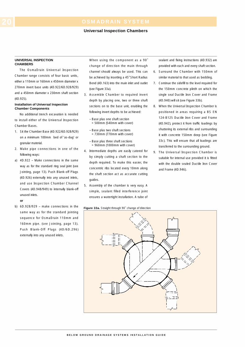
When using the component as a 90˚
change of direction the main through
channel should always be used. This can
be achieved by inserting a 45˚ Short Radius
Bend (4D.163) into the main inlet and outlet
(see Figure 33a).
3. Assemble Chamber to required invert
depth by placing one, two or three shaft
sections on to the base unit, enabling the
following invert depths to be achieved:
– Base plus one shaft section= 500mm (540mm with cover)
– Base plus two shaft sections= 730mm (770mm with cover)
– Base plus three shaft sections= 960mm (1000mm with cover)
4. Intermediate depths are easily catered for
by simply cutting a shaft section to the
depth required. To make this easier, the
concentric ribs located every 10mm along
the shaft section act as accurate cutting
guides.
5. Assembly of the chamber is very easy. A
simple, sealant filled interference joint
ensures a watertight installation. A tube of
sealant and fixing instructions (4D.932) are
provided with each and every shaft section.
6. Surround the Chamber with 150mm of
similar material to that used as bedding.
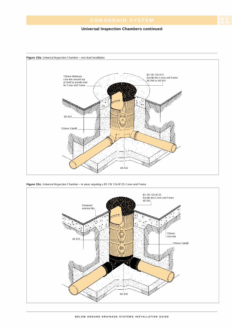
7. Continue the sidefill to the level required for
the 150mm concrete plinth on which the
single seal Ductile Iron Cover and Frame
(4D.940) will sit (see Figure 33b).
8. When the Universal Inspection Chamber is
positioned in areas requiring a BS EN
124-B125 Ductile Iron Cover and Frame
(4D.942), protect it from traffic loadings by
shuttering its external ribs and surrounding
it with concrete 150mm deep (see Figure
33c). This will ensure that all loadings are
transferred to the surrounding ground.
9. The Universal Inspection Chamber is
suitable for internal use provided it is fitted
with the double sealed Ductile Iron Cover
and Frame (4D.946).
OSMADRAIN SYSTEM
Universal Inspection Chambers
Figure 33a. Straight through 90˚ change of direction
B E L O W G R O U N D D R A I N A G E S Y S T E M S I N S T A L L A T I O N G U I D E
20
OSMADRAIN SYSTEM
Universal Inspection Chambers continued
Figure 33b. Universal Inspection Chamber – non-load installation
Figure 33c. Universal Inspection Chamber – in areas requiring a BS EN 124-B125 Cover and Frame
B E L O W G R O U N D D R A I N A G E S Y S T E M S I N S T A L L A T I O N G U I D E
21
150mm Sidefill
150mmconcrete
BS EN 124-B125Ductile Iron Cover and Frame4D.942
Shutteredexternal ribs
4D.925
6D.928
BS EN 124-A15Ductile Iron Cover and Frame4D.940 or 4D.941
150mm Minimumconcrete around top of shaft to provide bed for Cover and Frame
4D.925
150mm Sidefill
4D.922
OSMADRAIN SYSTEM
Manhole Bases
MANHOLES BASES
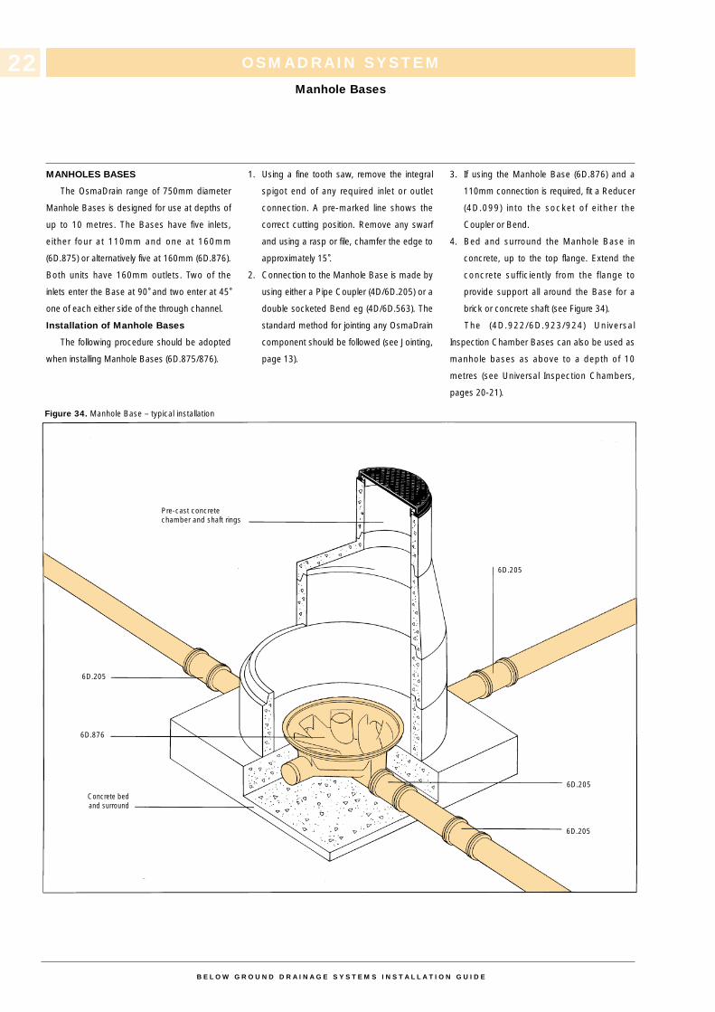
The OsmaDrain range of 750mm diameter
Manhole Bases is designed for use at depths of
up to 10 metres. The Bases have five inlets,
either four at 110mm and one at 160mm
(6D.875) or alternatively five at 160mm (6D.876).
Both units have 160mm outlets. Two of the
inlets enter the Base at 90˚ and two enter at 45˚one of each either side of the through channel.
Installation of Manhole Bases
The following procedure should be adopted
when installing Manhole Bases (6D.875/876).
1. Using a fine tooth saw, remove the integral
spigot end of any required inlet or outlet
connection. A pre-marked line shows the
correct cutting position. Remove any swarf
and using a rasp or file, chamfer the edge to
approximately 15˚.
2. Connection to the Manhole Base is made by
using either a Pipe Coupler (4D/6D.205) or a
double socketed Bend eg (4D/6D.563). The
standard method for jointing any OsmaDrain
component should be followed (see Jointing,
page 13).
3. If using the Manhole Base (6D.876) and a
110mm connection is required, fit a Reducer
(4D.099) into the socket of either the
Coupler or Bend.
4. Bed and surround the Manhole Base in
concrete, up to the top flange. Extend the
concrete sufficiently from the flange to
provide support all around the Base for a
brick or concrete shaft (see Figure 34).
The (4D.922/6D.923/924) Universal
Inspection Chamber Bases can also be used as
manhole bases as above to a depth of 10
metres (see Universal Inspection Chambers,
pages 20-21).
Figure 34. Manhole Base – typical installation
B E L O W G R O U N D D R A I N A G E S Y S T E M S I N S T A L L A T I O N G U I D E
22
Pre-cast concrete chamber and shaft rings
Concrete bed and surround
6D.205
6D.205
6D.205
6D.205
6D.876
INSTALLATION OF SEALEDACCESS FITTINGS
Manholes with Sealed Access Fittings are
generally constructed in the same way as
traditional manholes but as watertightness is
not critical, unlined brick or concrete manholes
may be permitted. Benching of the pipework is
essential.
1. Bed all Sealed Access Fittings in cement
mortar on a suitable concrete base.
2. Make pipe connections in the same way as
the standard ring seal jointing of fittings (see
Ring Seal Jointing, page 13).
3. Allow pipe ends to protrude beyond the edge
of the manhole base so that connections can
be made after the manhole walls have been
built.
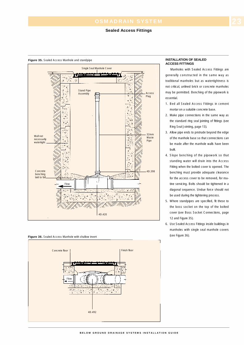
4. Slope benching of the pipework so that
standing water will drain into the Access
Fitting when the bolted cover is opened. The
benching must provide adequate clearance
for the access cover to be removed, for rou-
tine servicing. Bolts should be tightened in a
diagonal sequence. Undue force should not
be used during the tightening process.
5. Where standpipes are specified, fit these to
the boss socket on the top of the bolted
cover (see Boss Socket Connections, page
12 and Figure 35).
6. Use Sealed Access Fittings inside buildings in
manholes with single seal manhole covers
(see Figure 36).
OSMADRAIN SYSTEM
Sealed Access Fittings
Figure 35. Sealed Access Manhole and standpipe
Figure 36. Sealed Access Manhole with shallow invert
B E L O W G R O U N D D R A I N A G E S Y S T E M S I N S T A L L A T I O N G U I D E
23
Single Seal Manhole Cover
Stand PipeAssembly Access
Plug
32mmWastePipe
4D.398
4D.420
4D.492
Concrete floor Finish floor
Wall not necessarilywatertight
Concretebenchinglaid to fall
Flow
Flow
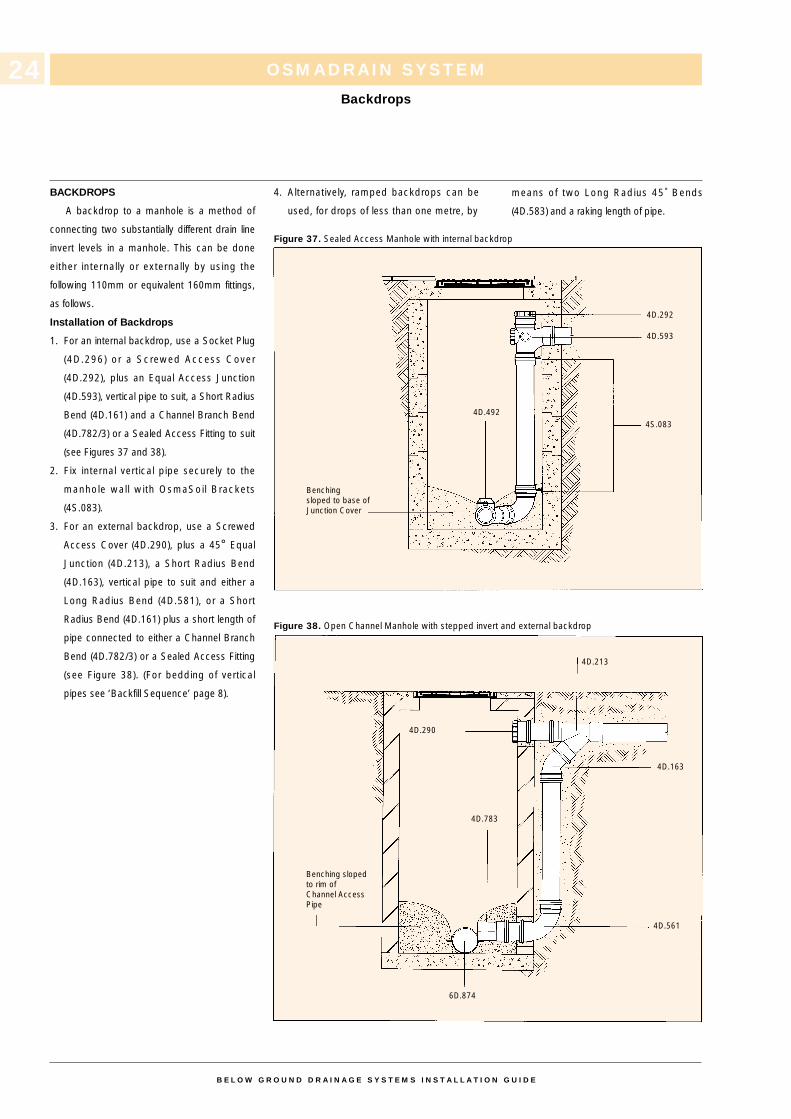
BACKDROPS
A backdrop to a manhole is a method of
connecting two substantially different drain line
invert levels in a manhole. This can be done
either internally or externally by using the
following 110mm or equivalent 160mm fittings,
as follows.
Installation of Backdrops
1. For an internal backdrop, use a Socket Plug
(4D.296) or a Screwed Access Cover
(4D.292), plus an Equal Access Junction
(4D.593), vertical pipe to suit, a Short Radius
Bend (4D.161) and a Channel Branch Bend
(4D.782/3) or a Sealed Access Fitting to suit
(see Figures 37 and 38).
2. Fix internal vertical pipe securely to the
manhole wall with OsmaSoil Brackets
(4S.083).
3. For an external backdrop, use a Screwed
Access Cover (4D.290), plus a 45° Equal
Junction (4D.213), a Short Radius Bend
(4D.163), vertical pipe to suit and either a
Long Radius Bend (4D.581), or a Short
Radius Bend (4D.161) plus a short length of
pipe connected to either a Channel Branch
Bend (4D.782/3) or a Sealed Access Fitting
(see Figure 38). (For bedding of vertical
pipes see ‘Backfill Sequence’ page 8).
4. Alternatively, ramped backdrops can be
used, for drops of less than one metre, by
means of two Long Radius 45˚ Bends
(4D.583) and a raking length of pipe.
OSMADRAIN SYSTEM
Backdrops
Figure 37. Sealed Access Manhole with internal backdrop
Figure 38. Open Channel Manhole with stepped invert and external backdrop
B E L O W G R O U N D D R A I N A G E S Y S T E M S I N S T A L L A T I O N G U I D E
24
Benching sloped to base ofJunction Cover
4D.292
4D.593
4D.213
4D.290
4D.163
4D.561
6D.874
4D.783
Benching slopedto rim of Channel AccessPipe
4S.0834D.492
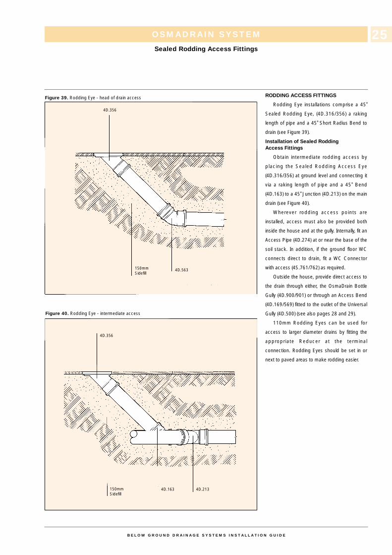
RODDING ACCESS FITTINGS
Rodding Eye installations comprise a 45˚Sealed Rodding Eye, (4D.316/356) a raking
length of pipe and a 45˚ Short Radius Bend to
drain (see Figure 39).
Installation of Sealed RoddingAccess Fittings
Obtain intermediate rodding access by
placing the Sealed Rodding Access Eye
(4D.316/356) at ground level and connecting it
via a raking length of pipe and a 45˚ Bend
(4D.163) to a 45˚ Junction (4D.213) on the main
drain (see Figure 40).
Wherever rodding access points are
installed, access must also be provided both
inside the house and at the gully. Internally, fit an
Access Pipe (4D.274) at or near the base of the
soil stack. In addition, if the ground floor WC
connects direct to drain, fit a WC Connector
with access (4S.761/762) as required.
Outside the house, provide direct access to
the drain through either, the OsmaDrain Bottle
Gully (4D.900/901) or through an Access Bend
(4D.169/569) fitted to the outlet of the Universal
Gully (4D.500) (see also pages 28 and 29).
110mm Rodding Eyes can be used for
access to larger diameter drains by fitting the
appropriate Reducer at the terminal
connection. Rodding Eyes should be set in or
next to paved areas to make rodding easier.
OSMADRAIN SYSTEM
Sealed Rodding Access Fittings
Figure 39. Rodding Eye - head of drain access
Figure 40. Rodding Eye - intermediate access
B E L O W G R O U N D D R A I N A G E S Y S T E M S I N S T A L L A T I O N G U I D E
25
4D.356
4D.563
4D.163 4D.213
4D.356
150mmSidefill
150mmSidefill
MANHOLE CONSTRUCTION
OsmaDrain Shallow, Multi-Base and
Universal Inspection Chambers offer an
alternative to traditional manholes and may be
used at depths up to 1 metre.
For access at depths greater than 1 metre,
construct a traditional manhole and use either, a)
the range of OsmaDrain Manhole Bases
(6D.875/876) or the Inspection Chamber Bases
(4D.922/6D.928/929) (see page 20) or b) the
range of OsmaDrain Channel or Sealed Access
Fittings.
Construct all manholes to meet the
requirements of the Building Regulations, BS
Codes of Practice and also BS 5955; Part 6:
1980.
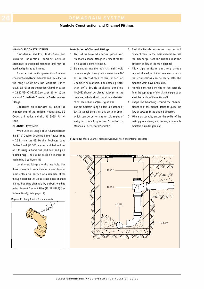
CHANNEL FITTINGS
When used as Long Radius Channel Bends
the 871/2˚ Double Socketed Long Radius Bend
(4D.581) and the 45˚ Double Socketed Long
Radius Bend (4D.583) are to be drilled and cut
on site using a hand drill, pad saw and plain
toothed rasp. The cut-out section is marked on
each fitting (see Figure 41).
Level invert fittings are also available. Use
these where falls are critical or where three or
more entries are needed on each side of the
through channel. Install as other open channel
fittings but joint channels by solvent welding
using Solvent Cement Filler (4S.383/384) (see
Solvent Weld Joints, page 14).
Installation of Channel Fittings
1. Bed all half-round channel pipes and
standard channel fittings in cement mortar
on a suitable concrete base.
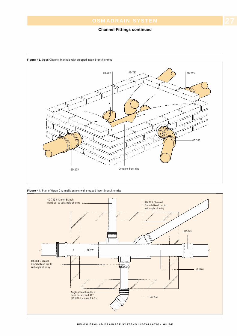
2. Side entries into the main channel should
have an angle of entry not greater than 90˚at the internal face of the Inspection
Chamber or Manhole. For entries greater
than 90˚ a double socketed bend (eg
4D.563) should be placed adjacent to the
manhole, which should provide a deviation
of not more than 45˚ (see Figure 43).
The OsmaDrain range offers a number of
3/4 Sectional Bends in sizes up to 160mm,
which can be cut on site to suit angles of
entry into any Inspection Chamber or
Manhole of between 30˚ and 90˚.
3. Bed the Bends in cement mortar and
connect them to the main channel so that
the discharge from the Branch is in the
direction of flow of the main channel.
4. Allow pipe or fitt ing ends to protrude
beyond the edge of the manhole base so
that connections can be made after the
manhole walls have been built.
5. Provide concrete benching to rise vertically
from the top edge of the channel pipe to at
least the height of the outlet soffit.
6. Shape the benchings round the channel
branches of the branch drains to guide the
flow of sewage in the desired direction.
7. Where practicable, ensure the soffits of the
main pipes entering and leaving a manhole
maintain a similar gradient.
OSMADRAIN SYSTEM
Manhole Construction and Channel Fittings
Figure 41. Long Radius Bend cut-outs
Figure 42. Open Channel Manhole with level invert and internal backdrop
B E L O W G R O U N D D R A I N A G E S Y S T E M S I N S T A L L A T I O N G U I D E
26
4D.292
4D.593
4D.793
4D.161
OSMADRAIN SYSTEM
Channel Fittings continued
Figure 43. Open Channel Manhole with stepped invert branch entries
Figure 44. Plan of Open Channel Manhole with stepped invert branch entries
B E L O W G R O U N D D R A I N A G E S Y S T E M S I N S T A L L A T I O N G U I D E
27
4D.782 4D.783 6D.205
4D.563
Concrete benching
4D.783 ChannelBranch Bend cut tosuit angle of entry
6D.205
6D.874
4D.563
Angle at Manhole facemust not exceed 90°(BS 8301, clause 7.6.2)
4D.783 ChannelBranch Bend cut to suit angle of entry
4D.782 Channel Branch Bend cut to suit angle of entry
6D.205
FLOW
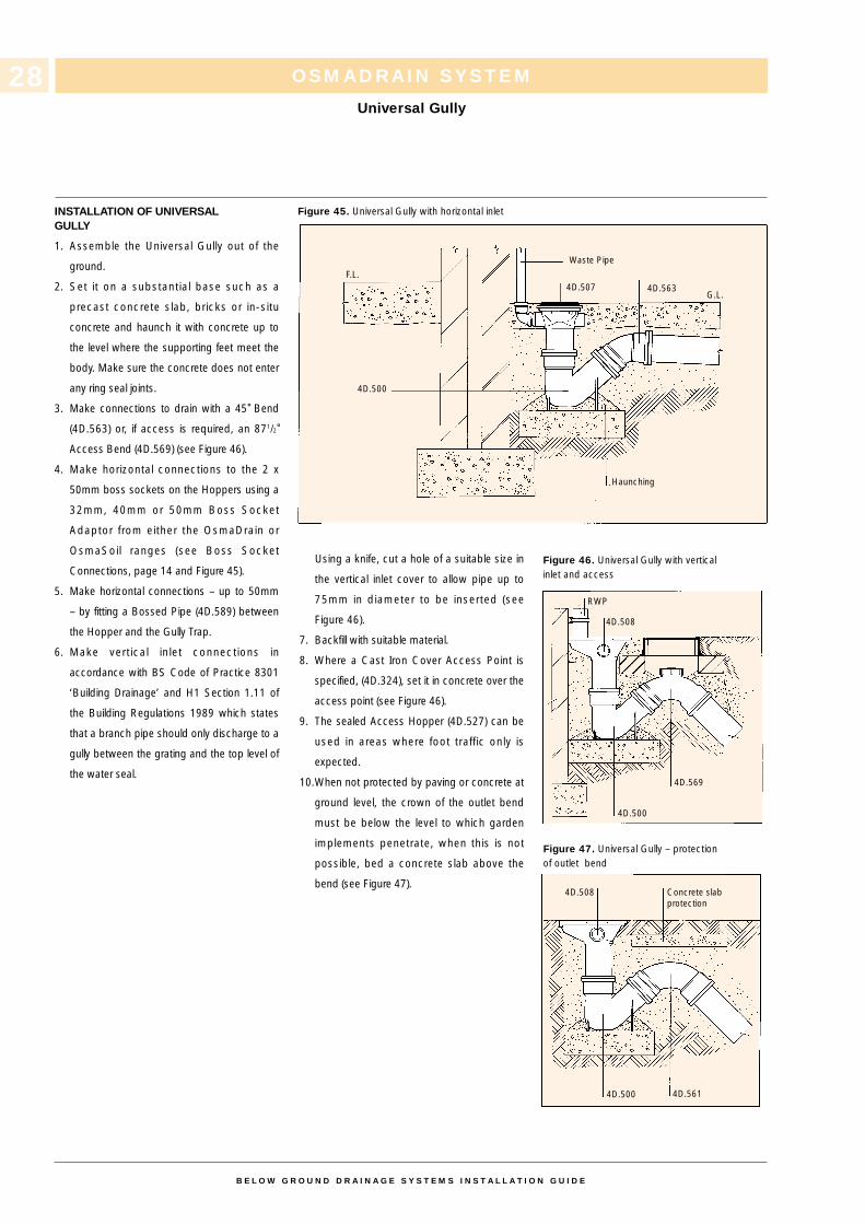
INSTALLATION OF UNIVERSALGULLY
1. Assemble the Universal Gully out of the
ground.
2. Set it on a substantial base such as a
precast concrete slab, bricks or in-situ
concrete and haunch it with concrete up to
the level where the supporting feet meet the
body. Make sure the concrete does not enter
any ring seal joints.
3. Make connections to drain with a 45˚ Bend
(4D.563) or, if access is required, an 871/2˚Access Bend (4D.569) (see Figure 46).
4. Make horizontal connections to the 2 x
50mm boss sockets on the Hoppers using a
32mm, 40mm or 50mm Boss Socket
Adaptor from either the OsmaDrain or
OsmaSoil ranges (see Boss Socket
Connections, page 14 and Figure 45).
5. Make horizontal connections – up to 50mm
– by fitting a Bossed Pipe (4D.589) between
the Hopper and the Gully Trap.
6. Make vertical inlet connections in
accordance with BS Code of Practice 8301
‘Building Drainage’ and H1 Section 1.11 of
the Building Regulations 1989 which states
that a branch pipe should only discharge to a
gully between the grating and the top level of
the water seal.
Using a knife, cut a hole of a suitable size in
the vertical inlet cover to allow pipe up to
75mm in diameter to be inserted (see
Figure 46).
7. Backfill with suitable material.
8. Where a Cast Iron Cover Access Point is
specified, (4D.324), set it in concrete over the
access point (see Figure 46).
9. The sealed Access Hopper (4D.527) can be
used in areas where foot traffic only is
expected.
10.When not protected by paving or concrete at
ground level, the crown of the outlet bend
must be below the level to which garden
implements penetrate, when this is not
possible, bed a concrete slab above the
bend (see Figure 47).
OSMADRAIN SYSTEM
Universal Gully
Figure 45. Universal Gully with horizontal inlet
Figure 46. Universal Gully with verticalinlet and access
Figure 47. Universal Gully – protectionof outlet bend
B E L O W G R O U N D D R A I N A G E S Y S T E M S I N S T A L L A T I O N G U I D E
28
Waste Pipe
4D.507 4D.563G.L.
F.L.
Haunching
RWP
4D.508
4D.569
4D.500
4D.500 4D.561
4D.508 Concrete slabprotection
4D.500
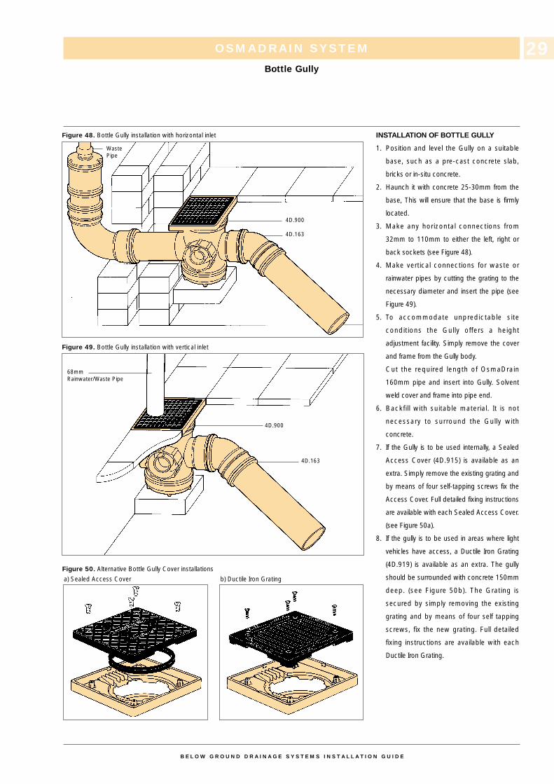
INSTALLATION OF BOTTLE GULLY
1. Position and level the Gully on a suitable
base, such as a pre-cast concrete slab,
bricks or in-situ concrete.
2. Haunch it with concrete 25-30mm from the
base, This will ensure that the base is firmly
located.
3. Make any horizontal connections from
32mm to 110mm to either the left, right or
back sockets (see Figure 48).
4. Make vertical connections for waste or
rainwater pipes by cutting the grating to the
necessary diameter and insert the pipe (see
Figure 49).
5. To accommodate unpredictable site
conditions the Gully offers a height
adjustment facility. Simply remove the cover
and frame from the Gully body.
Cut the required length of OsmaDrain
160mm pipe and insert into Gully. Solvent
weld cover and frame into pipe end.
6. Backfill with suitable material. It is not
necessary to surround the Gully with
concrete.
7. If the Gully is to be used internally, a Sealed
Access Cover (4D.915) is available as an
extra. Simply remove the existing grating and
by means of four self-tapping screws fix the
Access Cover. Full detailed fixing instructions
are available with each Sealed Access Cover.
(see Figure 50a).
8. If the gully is to be used in areas where light
vehicles have access, a Ductile Iron Grating
(4D.919) is available as an extra. The gully
should be surrounded with concrete 150mm
deep. (see Figure 50b). The Grating is
secured by simply removing the existing
grating and by means of four self tapping
screws, fix the new grating. Full detailed
fixing instructions are available with each
Ductile Iron Grating.
OSMADRAIN SYSTEM
Bottle Gully
Figure 48. Bottle Gully installation with horizontal inlet
a) Sealed Access Cover b) Ductile Iron Grating
Figure 50. Alternative Bottle Gully Cover installations
Figure 49. Bottle Gully installation with vertical inlet
B E L O W G R O U N D D R A I N A G E S Y S T E M S I N S T A L L A T I O N G U I D E
29
WastePipe
4D.900
4D.900
4D.163
4D.163
68mm Rainwater/Waste Pipe
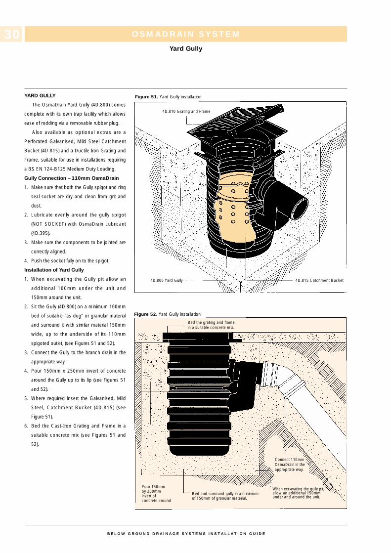
YARD GULLY
The OsmaDrain Yard Gully (4D.800) comes
complete with its own trap facility which allows
ease of rodding via a removable rubber plug.
Also available as optional extras are a
Perforated Galvanised, Mild Steel Catchment
Bucket (4D.815) and a Ductile Iron Grating and
Frame, suitable for use in installations requiring
a BS EN 124-B125 Medium Duty Loading.
Gully Connection – 110mm OsmaDrain
1. Make sure that both the Gully spigot and ring
seal socket are dry and clean from grit and
dust.
2. Lubricate evenly around the gully spigot
(NOT SOCKET) with OsmaDrain Lubricant
(4D.395).
3. Make sure the components to be jointed are
correctly aligned.
4. Push the socket fully on to the spigot.
Installation of Yard Gully
1. When excavating the Gully pit allow an
additional 100mm under the unit and
150mm around the unit.
2. Sit the Gully (4D.800) on a minimum 100mm
bed of suitable “as-dug” or granular material
and surround it with similar material 150mm
wide, up to the underside of its 110mm
spigoted outlet, (see Figures 51 and 52).
3. Connect the Gully to the branch drain in the
appropriate way.
4. Pour 150mm x 250mm invert of concrete
around the Gully up to its lip (see Figures 51
and 52).
5. Where required insert the Galvanised, Mild
Steel, Catchment Bucket (4D.815) (see
Figure 51).
6. Bed the Cast-Iron Grating and Frame in a
suitable concrete mix (see Figures 51 and
52).
Figure 51. Yard Gully installation
Figure 52. Yard Gully installation
OSMADRAIN SYSTEM
Yard Gully
B E L O W G R O U N D D R A I N A G E S Y S T E M S I N S T A L L A T I O N G U I D E
30
4D.810 Grating and Frame
4D.815 Catchment Bucket
Bed the grating and framein a suitable concrete mix.
Connect 110mmOsmaDrain in theappropriate way.
Pour 150mm by 250mminvert of concrete around
Bed and surround gully in a minimumof 150mm of granular material.
When excavating the gully pit,allow an additional 150mmunder and around the unit.
4D.800 Yard Gully
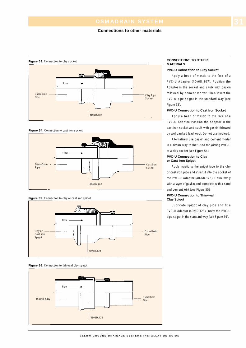
CONNECTIONS TO OTHERMATERIALS
PVC-U Connection to Clay Socket
Apply a bead of mastic to the face of a
PVC-U Adaptor (4D/6D.107). Position the
Adaptor in the socket and caulk with gaskin
followed by cement mortar. Then insert the
PVC-U pipe spigot in the standard way (see
Figure 53).
PVC-U Connection to Cast Iron Socket
Apply a bead of mastic to the face of a
PVC-U Adaptor. Position the Adaptor in the
cast iron socket and caulk with gaskin followed
by well caulked lead wool. Do not use hot lead.
Alternatively use gaskin and cement mortar
in a similar way to that used for jointing PVC-U
to a clay socket (see Figure 54).
PVC-U Connection to Clayor Cast Iron Spigot
Apply mastic to the spigot face to the clay
or cast iron pipe and insert it into the socket of
the PVC-U Adaptor (4D/6D.128). Caulk firmly
with a layer of gaskin and complete with a sand
and cement joint (see Figure 55).
PVC-U Connection to Thin-wallClay Spigot
Lubricate spigot of clay pipe and fit a
PVC-U Adaptor (4D/6D.129). Insert the PVC-U
pipe spigot in the standard way (see Figure 56).
OSMADRAIN SYSTEM
Connections to other materials
Figure 53. Connection to clay socket
Figure 54. Connection to cast iron socket
Figure 55. Connection to clay or cast iron spigot
Figure 56. Connection to thin-wall clay spigot
B E L O W G R O U N D D R A I N A G E S Y S T E M S I N S T A L L A T I O N G U I D E
31
Flow
Flow
Flow
Flow
4D/6D.107
4D/6D.107
4D/6D.128
4D/6D.129
OsmaDrainPipe
OsmaDrainPipe
OsmaDrainPipe
OsmaDrainPipe
Clay PipeSocket
Cast IronSocket
Clay orCast IronSpigot
150mm Clay
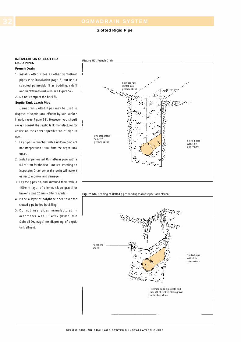
INSTALLATION OF SLOTTEDRIGID PIPES
French Drain
1. Install Slotted Pipes as other OsmaDrain
pipes (see Installation page 6) but use a
selected permeable fill as bedding, sidefill
and backfill material (also see Figure 57).
2. Do not compact the backfill.
Septic Tank Leach Pipe
OsmaDrain Slotted Pipes may be used to
dispose of septic tank effluent by sub-surface
irrigation (see Figure 58). However, you should
always consult the septic tank manufacturer for
advice on the correct specification of pipe to
use.
1. Lay pipes in trenches with a uniform gradient
not steeper than 1:200 from the septic tank
outlet.
2. Install unperforated OsmaDrain pipe with a
fall of 1:30 for the first 3 metres. Installing an
Inspection Chamber at this point will make it
easier to monitor land damage.
3. Lay the pipes on, and surround them with, a
150mm layer of clinker, clean gravel or
broken stone 20mm – 50mm grade.
4. Place a layer of polythene sheet over the
slotted pipe before backfilling.
5. Do not use pipes manufactured in
accordance with BS 4962 (OsmaDrain
Subsoil Drainage) for disposing of septic
tank effluent.
Figure 57. French Drain
Figure 58. Bedding of slotted pipes for disposal of septic tank effluent
OSMADRAIN SYSTEM
Slotted Rigid Pipe
B E L O W G R O U N D D R A I N A G E S Y S T E M S I N S T A L L A T I O N G U I D E
32
Camber runsrainfall intopermeable fill
Slotted pipewith slotsuppermost
Slotted pipewith slotsdownwards
Uncompactedselected permeable fill
150mm bedding sidefill and backfill of clinker, clean gravel or broken stone
Polythenesheet
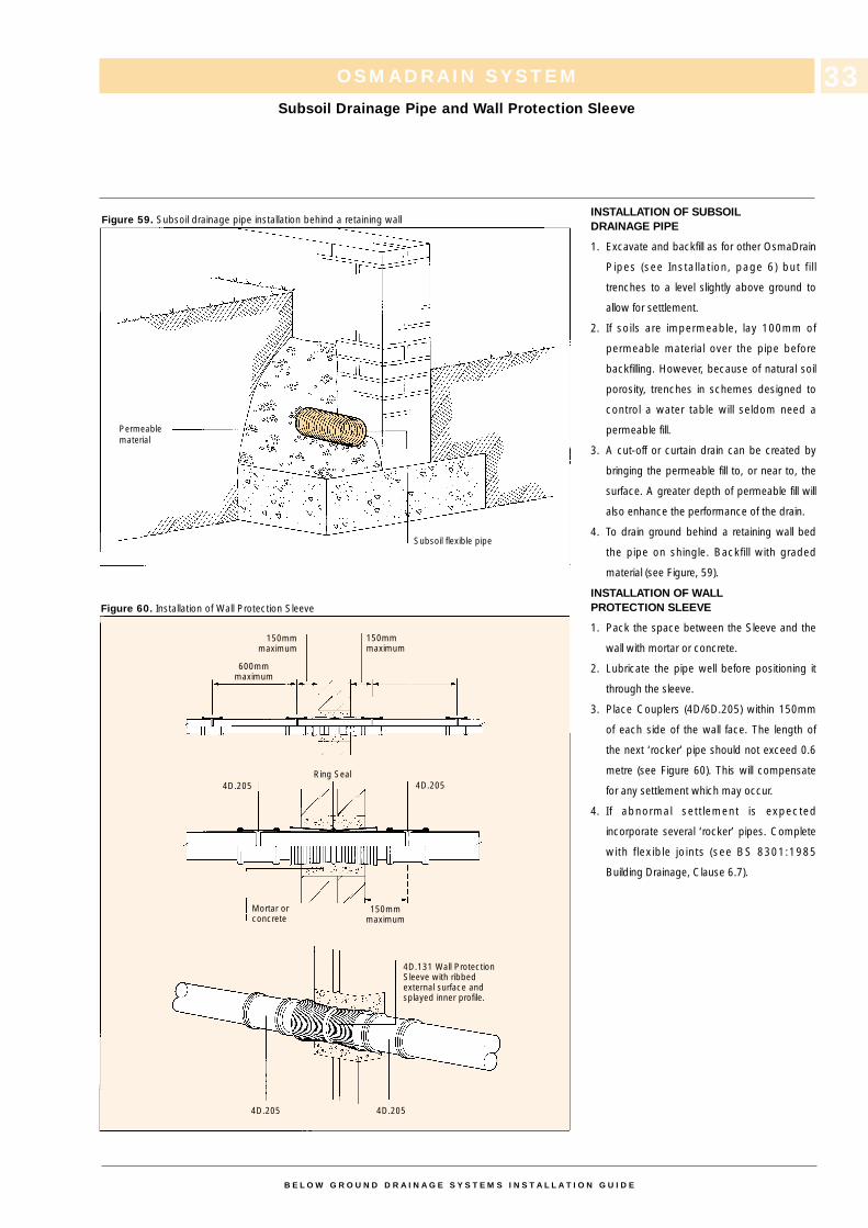
INSTALLATION OF SUBSOILDRAINAGE PIPE
1. Excavate and backfill as for other OsmaDrain
Pipes (see Installation, page 6) but fil l
trenches to a level slightly above ground to
allow for settlement.
2. If soils are impermeable, lay 100mm of
permeable material over the pipe before
backfilling. However, because of natural soil
porosity, trenches in schemes designed to
control a water table will seldom need a
permeable fill.
3. A cut-off or curtain drain can be created by
bringing the permeable fill to, or near to, the
surface. A greater depth of permeable fill will
also enhance the performance of the drain.
4. To drain ground behind a retaining wall bed
the pipe on shingle. Backfill with graded
material (see Figure, 59).
INSTALLATION OF WALLPROTECTION SLEEVE
1. Pack the space between the Sleeve and the
wall with mortar or concrete.
2. Lubricate the pipe well before positioning it
through the sleeve.
3. Place Couplers (4D/6D.205) within 150mm
of each side of the wall face. The length of
the next ‘rocker’ pipe should not exceed 0.6
metre (see Figure 60). This will compensate
for any settlement which may occur.
4. If abnormal settlement is expected
incorporate several ‘rocker’ pipes. Complete
with flexible joints (see BS 8301:1985
Building Drainage, Clause 6.7).
OSMADRAIN SYSTEM
Subsoil Drainage Pipe and Wall Protection Sleeve
Figure 59. Subsoil drainage pipe installation behind a retaining wall
Figure 60. Installation of Wall Protection Sleeve
B E L O W G R O U N D D R A I N A G E S Y S T E M S I N S T A L L A T I O N G U I D E
33
Permeablematerial
Subsoil flexible pipe
150mm maximum
4D.205
4D.205 4D.205
150mm maximum
4D.205
Mortar orconcrete
4D.131 Wall ProtectionSleeve with ribbedexternal surface andsplayed inner profile.
600mmmaximum
150mmmaximum
Ring Seal
OSMADRAIN SYSTEM
Maintenance and Access for Cleaning
B E L O W G R O U N D D R A I N A G E S Y S T E M S I N S T A L L A T I O N G U I D E
34
MAINTENANCE
Building Regulations and Local Authority
Bylaws state that manholes, inspection cham-
bers and rodding eyes must be provided to give
ready access to underground drains for mainte-
nance and cleaning.
Remove inspection chamber covers
periodically and clean the benching.
Check the complete drainage system
periodically and clean, making good any defects
if necessary.
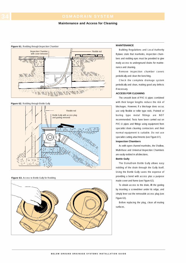
ACCESS FOR CLEANING
The smooth bore of PVC-U pipes combined
with their longer lengths reduce the risk of
blockages. However, if a blockage does occur,
use only flexible or roller type rods. Pointed or
boring type metal fittings are NOT
recommended. Tests have been carried out on
PVC-U pipes and fittings using equipment from
specialist drain cleaning contractors and their
normal equipment is suitable. Do not use
specialist cutting attachments (see Figure 61).
Inspection Chambers
As with open channel manholes, the Shallow,
Multi-Base and Universal Inspection Chambers
are easily rodded in all directions.
Bottle Gully
The OsmaDrain Bottle Gully allows easy
rodding of the drain through the Gully itself.
Using the Bottle Gully saves the expense of
providing a bend with access plus a purpose
made cover and frame (see Figure 62).
To obtain access to the drain, lift the grating
by inserting a screwdriver under its edge, and
simply lever out the removable access plug (see
Figure 63).
Before replacing the plug, clean all mating
surfaces.
Figure 61. Rodding through Inspection Chamber
Figure 62. Rodding through Bottle Gully
Figure 63. Access to Bottle Gully for Rodding
Inspection Chamberwith cover removed
Bottle Gully with access plugand grating removed
Flexible rod
Flexible rod

OSMA ULTRARIB SYSTEM
Contents
B E L O W G R O U N D D R A I N A G E S Y S T E M S I N S T A L L A T I O N G U I D E
35
CONTENTS PAGE
Jointing 36
Inspection Chamber 37
Manhole Bases 38
Channel Access Fittings 39-40
Road Gully 41
Connections to other Materials 42-43
Slip Junctions 44-45
OSMA ULTRARIB SYSTEM
Jointing
B E L O W G R O U N D D R A I N A G E S Y S T E M S I N S T A L L A T I O N G U I D E
36
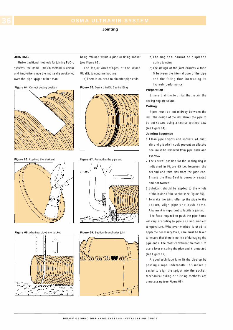
JOINTING
Unlike traditional methods for jointing PVC-U
systems, the Osma UltraRib method is unique
and innovative, since the ring seal is positioned
over the pipe spigot rather than
being retained within a pipe or fitting socket
(see Figure 65).
The major advantages of the Osma
UltraRib jointing method are:
a) There is no need to chamfer pipe ends
b) The r ing seal cannot be displaced
during jointing
c) The design of the joint ensures a flush
fit between the internal bore of the pipe
and the f i t t ing thus increasing i ts
hydraulic performance.
Preparation
Ensure that the two ribs that retain the
sealing ring are sound.
Cutting
Pipes must be cut midway between the
ribs. The design of the ribs allows the pipe to
be cut square using a coarse toothed saw
(see Figure 64).
Jointing Sequence
1. Clean pipe spigots and sockets. All dust,
dirt and grit which could prevent an effective
seal must be removed from pipe ends and
sockets.
2.The correct position for the sealing ring is
indicated in Figure 65 i.e. between the
second and third ribs from the pipe end.
Ensure the Ring Seal is correctly seated
and not twisted.
3.Lubricant should be applied to the whole
of the inside of the socket (see Figure 66).
4.To make the joint, offer up the pipe to the
socket, a l ign pipe and push home.
Alignment is important to facilitate jointing.
The force required to push the pipe home
will vary according to pipe size and ambient
temperature. Whatever method is used to
apply the necessary force, care must be taken
to ensure that there is no risk of damaging the
pipe ends. The most convenient method is to
use a lever ensuring the pipe end is protected
(see Figure 67).
A good technique is to lift the pipe up by
passing a rope underneath. This makes it
easier to align the spigot into the socket.
Mechanical pulling or pushing methods are
unnecessary (see Figure 68).
Figure 64. Correct cutting position
Figure 66. Applying the lubricant
Figure 68. Aligning spigot into socket
Figure 65. Osma UltraRib Sealing Ring
Figure 67. Protecting the pipe end
Figure 69. Section through pipe joint
OSMA ULTRARIB SYSTEM
Inspection Chamber
B E L O W G R O U N D D R A I N A G E S Y S T E M S I N S T A L L A T I O N G U I D E
37
INSPECTION CHAMBER
The Osma UltraRib range of Inspection
Chambers consist of three basic units, either a
150mm x 150mm x 450mm or a 150mm x
110mm x 450mm base section (6UR.928/929)
together with a 450mm diameter shaft section
(4D.925).
The 6UR.929 base unit comes complete with
four 110mm integral socketed side inlets, two at
90° and two at 45°, one of each, either side of
the 150mm through channel.
The 6UR.928 base unit is supplied with a single
Blank-off plug, for use to blank off any unusual
inlets. Both units are supplied in opaque bags,
which are sealed to protect the ring seals.
Installation of Inspection ChamberComponents
No additional trench excavation is needed to
install the Inspection Chamber.
1. Sit the Inspection Chamber Base
(6UR.928/929) on a minimum of 100mm bed
of ‘as-dug’ or granular material.
2. Make pipe connections in one of the
following ways:
a) 6UR.928 - Make connections in the same
way as for the standard jointing sequence for
Osma UltraRib pipe (see Jointing, page 36).
b) 6UR.929 - Make connections in the same
way as for the standard jointing sequence for
OsmaDrain pipe (see Jointing, page 13) and
for Osma UltraRib pipe (see Jointing,
page 36).
When using the components as a 90˚change of direction, the main through
channel should always be used. This can
be achieved by offering up the socket of
the 45˚ Short Radius Bend (6UR.163) to
the main inlet and outlet spigots of the
through channel.
4. Assemble Chamber to the required invert
depth by placing one, two or three shaft
sections onto the base unit, enabling the
following invert depths to be achieved.
– Base plus one shaft section= 500mm (540mm with cover)
– Base plus two shaft sections= 730mm (770mm with cover)
– Base plus three shaft sections= 960mm (1000mm with cover)
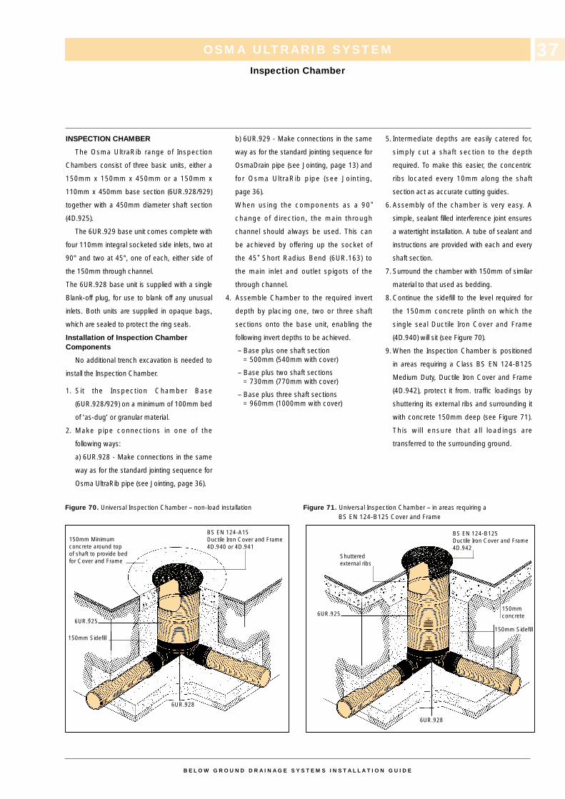
5. Intermediate depths are easily catered for,
simply cut a shaft section to the depth
required. To make this easier, the concentric
ribs located every 10mm along the shaft
section act as accurate cutting guides.
6. Assembly of the chamber is very easy. A
simple, sealant filled interference joint ensures
a watertight installation. A tube of sealant and
instructions are provided with each and every
shaft section.
7. Surround the chamber with 150mm of similar
material to that used as bedding.
8. Continue the sidefill to the level required for
the 150mm concrete plinth on which the
single seal Ductile Iron Cover and Frame
(4D.940) will sit (see Figure 70).
9. When the Inspection Chamber is positioned
in areas requiring a Class BS EN 124-B125
Medium Duty, Ductile Iron Cover and Frame
(4D.942), protect it from. traffic loadings by
shuttering its external ribs and surrounding it
with concrete 150mm deep (see Figure 71).
This wil l ensure that al l loadings are
transferred to the surrounding ground.
Figure 70. Universal Inspection Chamber – non-load installation Figure 71. Universal Inspection Chamber – in areas requiring a BS EN 124-B125 Cover and Frame
6UR.9256UR.925
6UR.928
6UR.928
150mm Sidefill
150mmconcrete
BS EN 124-B125Ductile Iron Cover and Frame4D.942
Shutteredexternal ribs
BS EN 124-A15Ductile Iron Cover and Frame4D.940 or 4D.941
150mm Minimumconcrete around top of shaft to provide bed for Cover and Frame
150mm Sidefill
OSMA ULTRARIB SYSTEM
Manhole Bases
B E L O W G R O U N D D R A I N A G E S Y S T E M S I N S T A L L A T I O N G U I D E
38
1
MANHOLE BASES
The Osma UltraRib range of 750mm
diameter Manhole Bases are designed for use at
depths of up to 10 metres. The range consists
of the following configurations:-
6UR.875 150mm diameter through channel with
four 110mm BS 4660 inlets.
6UR.876 150mm diameter through channel
with four 150mm diameter inlets.
9UR.877 225mm diameter through channel with
two 225mm diameter inlets.
9UR.878 225mm diameter through channel with
four 150mm diameter inlets.
In three of the above cases (6UR.875/876
and 9UR.878) two of the 110mm or 150mm
inlets enter the Bases at 90˚ and two enter at 45˚one each, either side of the 150mm or 225mm
through channel.
In the case of the 9UR.877 base, the inlets
enter the base at 90˚ one either side of its
225mm through channel.
All base units come complete with ring seals
pre-fitted, one on each of the 150mm or
225mm inlets or outlets. The units are supplied
in opaque bags which are sealed to protect the
ring seals.
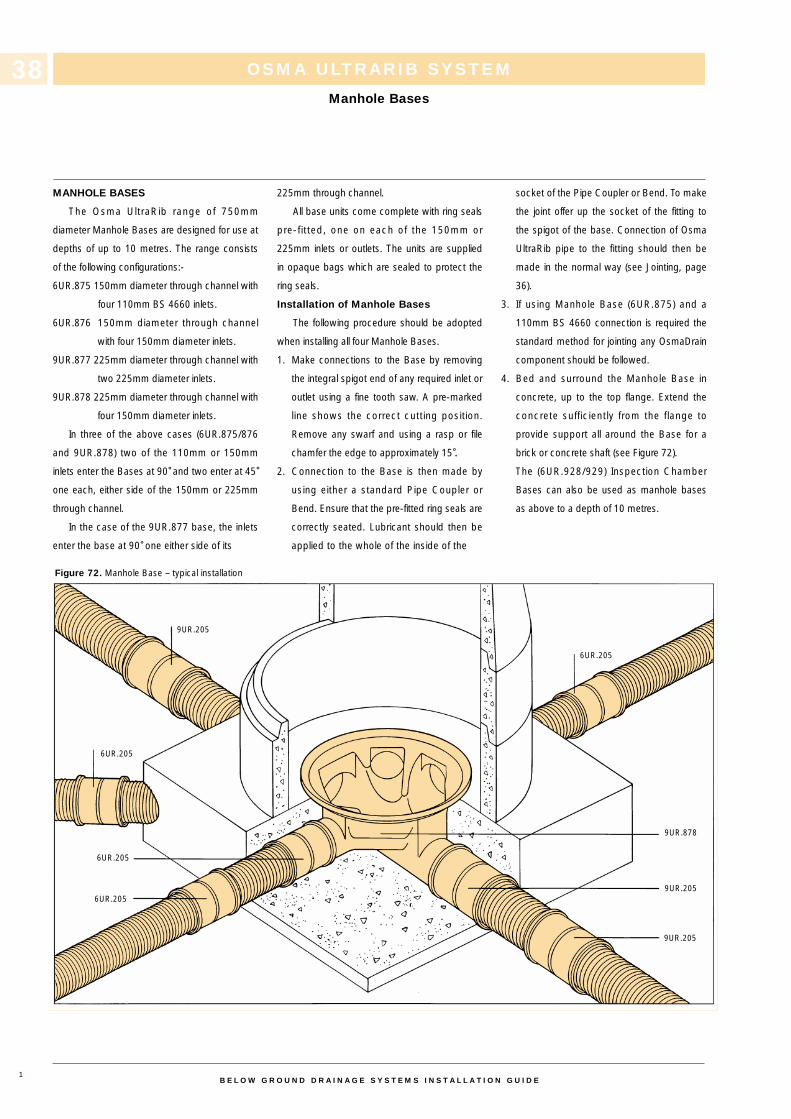
Installation of Manhole Bases
The following procedure should be adopted
when installing all four Manhole Bases.
1. Make connections to the Base by removing
the integral spigot end of any required inlet or
outlet using a fine tooth saw. A pre-marked
line shows the correct cutting position.
Remove any swarf and using a rasp or file
chamfer the edge to approximately 15˚.
2. Connection to the Base is then made by
using either a standard Pipe Coupler or
Bend. Ensure that the pre-fitted ring seals are
correctly seated. Lubricant should then be
applied to the whole of the inside of the
socket of the Pipe Coupler or Bend. To make
the joint offer up the socket of the fitting to
the spigot of the base. Connection of Osma
UltraRib pipe to the fitting should then be
made in the normal way (see Jointing, page
36).
3. If using Manhole Base (6UR.875) and a
110mm BS 4660 connection is required the
standard method for jointing any OsmaDrain
component should be followed.
4. Bed and surround the Manhole Base in
concrete, up to the top flange. Extend the
concrete sufficiently from the flange to
provide support all around the Base for a
brick or concrete shaft (see Figure 72).
The (6UR.928/929) Inspection Chamber
Bases can also be used as manhole bases
as above to a depth of 10 metres.
Figure 72. Manhole Base – typical installation
9UR.205
6UR.205
6UR.205
6UR.205
6UR.205
9UR.878
9UR.205
9UR.205
OSMA ULTRARIB SYSTEM
Channel Access Fittings
B E L O W G R O U N D D R A I N A G E S Y S T E M S I N S T A L L A T I O N G U I D E
39
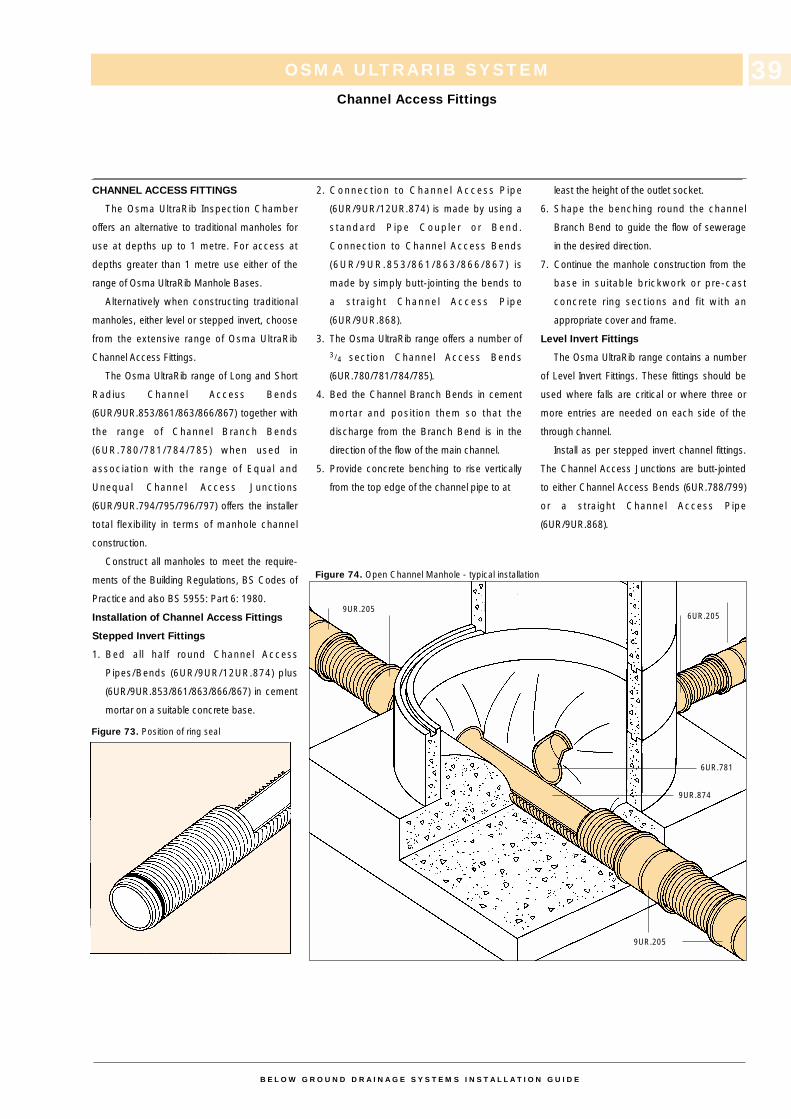
CHANNEL ACCESS FITTINGS
The Osma UltraRib Inspection Chamber
offers an alternative to traditional manholes for
use at depths up to 1 metre. For access at
depths greater than 1 metre use either of the
range of Osma UltraRib Manhole Bases.
Alternatively when constructing traditional
manholes, either level or stepped invert, choose
from the extensive range of Osma UltraRib
Channel Access Fittings.
The Osma UltraRib range of Long and Short
Radius Channel Access Bends
(6UR/9UR.853/861/863/866/867) together with
the range of Channel Branch Bends
(6UR.780/781/784/785) when used in
association with the range of Equal and
Unequal Channel Access Junctions
(6UR/9UR.794/795/796/797) offers the installer
total flexibility in terms of manhole channel
construction.
Construct all manholes to meet the require-
ments of the Building Regulations, BS Codes of
Practice and also BS 5955: Part 6: 1980.
Installation of Channel Access Fittings
Stepped Invert Fittings
1. Bed all half round Channel Access
Pipes/Bends (6UR/9UR/12UR.874) plus
(6UR/9UR.853/861/863/866/867) in cement
mortar on a suitable concrete base.
2. Connect ion to Channel Access Pipe
(6UR/9UR/12UR.874) is made by using a
standard Pipe Coupler or Bend.
Connection to Channel Access Bends
(6UR/9UR.853/861/863/866/867) is
made by simply butt-jointing the bends to
a stra ight Channel Access Pipe
(6UR/9UR.868).
3. The Osma UltraRib range offers a number of3/4 section Channel Access Bends
(6UR.780/781/784/785).
4. Bed the Channel Branch Bends in cement
mortar and position them so that the
discharge from the Branch Bend is in the
direction of the flow of the main channel.
5. Provide concrete benching to rise vertically
from the top edge of the channel pipe to at
least the height of the outlet socket.
6. Shape the benching round the channel
Branch Bend to guide the flow of sewerage
in the desired direction.
7. Continue the manhole construction from the
base in suitable brickwork or pre-cast
concrete ring sections and fit with an
appropriate cover and frame.
Level Invert Fittings
The Osma UltraRib range contains a number
of Level Invert Fittings. These fittings should be
used where falls are critical or where three or
more entries are needed on each side of the
through channel.
Install as per stepped invert channel fittings.
The Channel Access Junctions are butt-jointed
to either Channel Access Bends (6UR.788/799)
or a straight Channel Access Pipe
(6UR/9UR.868).
Figure 73. Position of ring seal
Figure 74. Open Channel Manhole - typical installation
9UR.205
9UR.874
6UR.781
6UR.2059UR.205
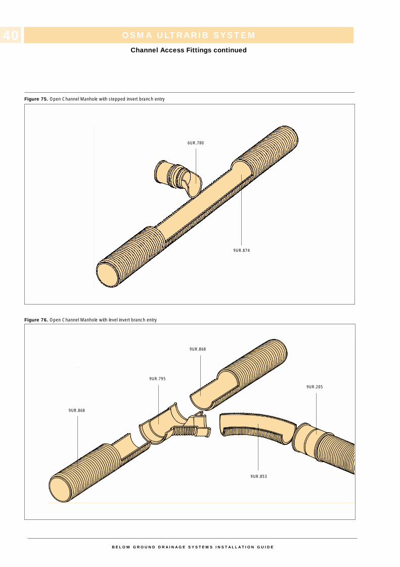
OSMA ULTRARIB SYSTEM
Channel Access Fittings continued
B E L O W G R O U N D D R A I N A G E S Y S T E M S I N S T A L L A T I O N G U I D E
40
Figure 75. Open Channel Manhole with stepped invert branch entry
Figure 76. Open Channel Manhole with level invert branch entry
6UR.780
9UR.874
9UR.868
9UR.853
9UR.205
9UR.868
9UR.795
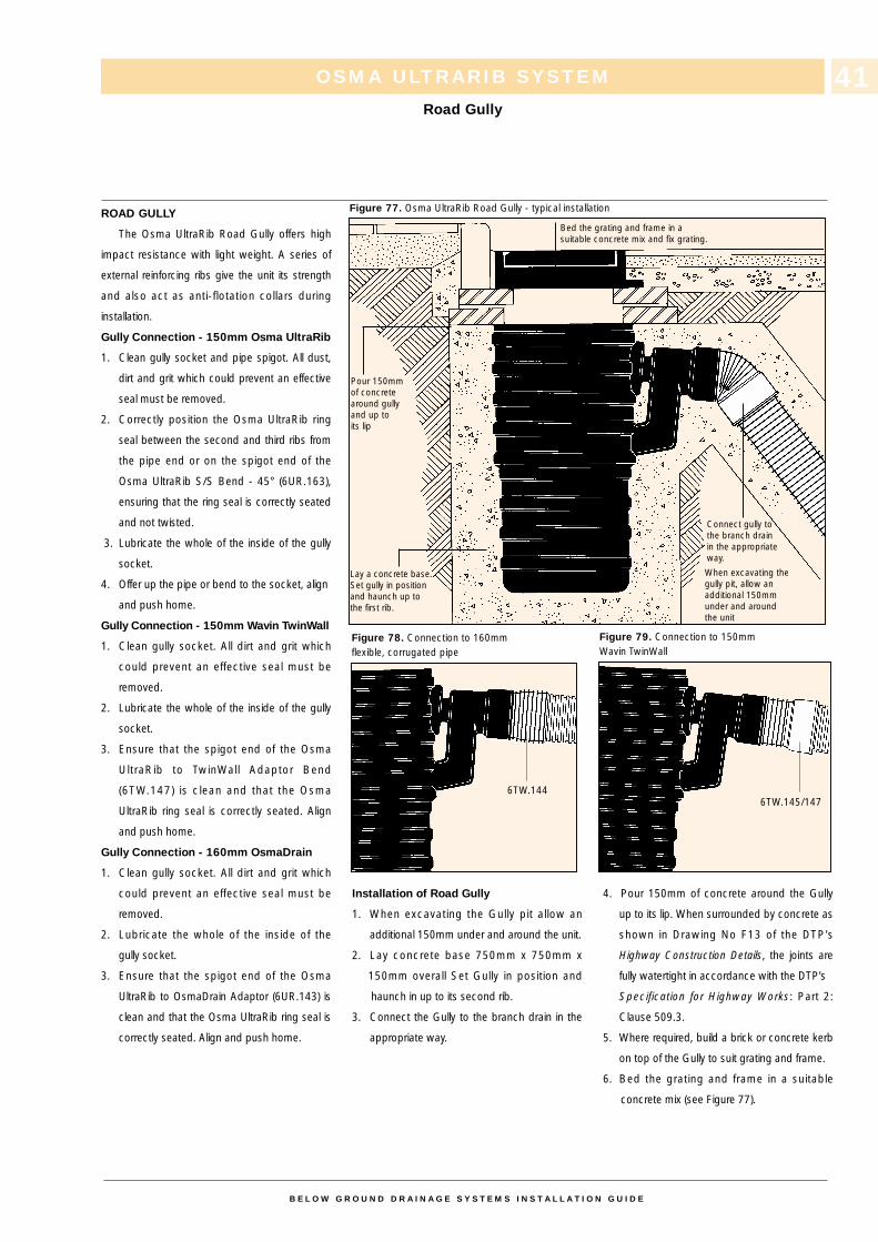
ROAD GULLY
The Osma UltraRib Road Gully offers high
impact resistance with light weight. A series of
external reinforcing ribs give the unit its strength
and also act as anti-flotation collars during
installation.
Gully Connection - 150mm Osma UltraRib
1. Clean gully socket and pipe spigot. All dust,
dirt and grit which could prevent an effective
seal must be removed.
2. Correctly position the Osma UltraRib ring
seal between the second and third ribs from
the pipe end or on the spigot end of the
Osma UltraRib S/S Bend - 45° (6UR.163),
ensuring that the ring seal is correctly seated
and not twisted.
3. Lubricate the whole of the inside of the gully
socket.
4. Offer up the pipe or bend to the socket, align
and push home.
Gully Connection - 150mm Wavin TwinWall
1. Clean gully socket. All dirt and grit which
could prevent an effective seal must be
removed.
2. Lubricate the whole of the inside of the gully
socket.
3. Ensure that the spigot end of the Osma
UltraRib to TwinWall Adaptor Bend
(6TW.147) is clean and that the Osma
UltraRib ring seal is correctly seated. Align
and push home.
Gully Connection - 160mm OsmaDrain
1. Clean gully socket. All dirt and grit which
could prevent an effective seal must be
removed.
2. Lubricate the whole of the inside of the
gully socket.
3. Ensure that the spigot end of the Osma
UltraRib to OsmaDrain Adaptor (6UR.143) is
clean and that the Osma UltraRib ring seal is
correctly seated. Align and push home.
Installation of Road Gully
1. When excavating the Gully pit allow an
additional 150mm under and around the unit.
2. Lay concrete base 750mm x 750mm x
150mm overall Set Gully in position and
haunch in up to its second rib.
3. Connect the Gully to the branch drain in the
appropriate way.
4. Pour 150mm of concrete around the Gully
up to its lip. When surrounded by concrete as
shown in Drawing No F13 of the DTP’s
Highway Construction Details, the joints are
fully watertight in accordance with the DTP’s
Specification for Highway Works: Part 2:
Clause 509.3.
5. Where required, build a brick or concrete kerb
on top of the Gully to suit grating and frame.
6. Bed the grating and frame in a suitable
concrete mix (see Figure 77).
OSMA ULTRARIB SYSTEM
Road Gully
Figure 77. Osma UltraRib Road Gully - typical installation
Figure 78. Connection to 160mm flexible, corrugated pipe
Figure 79. Connection to 150mmWavin TwinWall
B E L O W G R O U N D D R A I N A G E S Y S T E M S I N S T A L L A T I O N G U I D E
41
When excavating thegully pit, allow anadditional 150mmunder and around the unit
Lay a concrete base.Set gully in positionand haunch up tothe first rib.
Connect gully tothe branch drainin the appropriateway.
Pour 150mmof concretearound gullyand up to its lip
Bed the grating and frame in a suitable concrete mix and fix grating.
6TW.1446TW.145/147
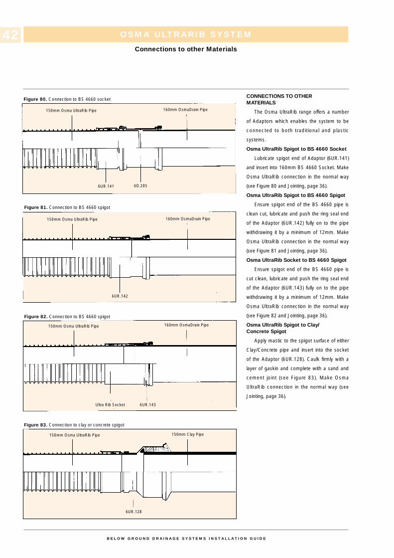
CONNECTIONS TO OTHERMATERIALS
The Osma UltraRib range offers a number
of Adaptors which enables the system to be
connected to both traditional and plastic
systems.
Osma UltraRib Spigot to BS 4660 Socket
Lubricate spigot end of Adaptor (6UR.141)
and insert into 160mm BS 4660 Socket. Make
Osma UltraRib connection in the normal way
(see Figure 80 and Jointing, page 36).
Osma UltraRib Spigot to BS 4660 Spigot
Ensure spigot end of the BS 4660 pipe is
clean cut, lubricate and push the ring seal end
of the Adaptor (6UR.142) fully on to the pipe
withdrawing it by a minimum of 12mm. Make
Osma UltraRib connection in the normal way
(see Figure 81 and Jointing, page 36).
Osma UltraRib Socket to BS 4660 Spigot
Ensure spigot end of the BS 4660 pipe is
cut clean, lubricate and push the ring seal end
of the Adaptor (6UR.143) fully on to the pipe
withdrawing it by a minimum of 12mm. Make
Osma UltraRib connection in the normal way
(see Figure 82 and Jointing, page 36).
Osma UltraRib Spigot to Clay/Concrete Spigot
Apply mastic to the spigot surface of either
Clay/Concrete pipe and insert into the socket
of the Adaptor (6UR.128). Caulk firmly with a
layer of gaskin and complete with a sand and
cement joint (see Figure 83). Make Osma
UltraRib connection in the normal way (see
Jointing, page 36).
OSMA ULTRARIB SYSTEM
Connections to other Materials
Figure 80. Connection to BS 4660 socket
Figure 81. Connection to BS 4660 spigot
Figure 82. Connection to BS 4660 spigot
Figure 83. Connection to clay or concrete spigot
B E L O W G R O U N D D R A I N A G E S Y S T E M S I N S T A L L A T I O N G U I D E
42
150mm Osma UltraRib Pipe
150mm Osma UltraRib Pipe
150mm Osma UltraRib Pipe
6UR.142
Ultra Rib Socket 6UR.143
6UR.128
160mm OsmaDrain Pipe
160mm OsmaDrain Pipe
150mm Clay Pipe
150mm Osma UltraRib Pipe
6UR.141 6D.205
160mm OsmaDrain Pipe
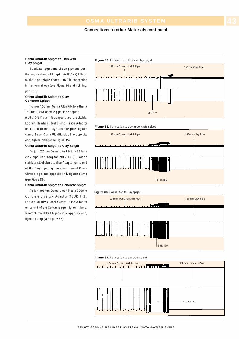
Osma UltraRib Spigot to Thin-wallClay Spigot
Lubricate spigot end of clay pipe and push
the ring seal end of Adaptor (6UR.129) fully on
to the pipe. Make Osma UltraRib connection
in the normal way (see Figure 84 and Jointing,
page 36).
Osma UltraRib Spigot to Clay/Concrete Spigot
To join 150mm Osma UltraRib to either a
150mm Clay/Concrete pipe use Adaptor
(6UR.106) if push-fit adaptors are unsuitable.
Loosen stainless steel clamps, slide Adaptor
on to end of the Clay/Concrete pipe, tighten
clamp. Insert Osma UltraRib pipe into opposite
end, tighten clamp (see Figure 85).
Osma UltraRib Spigot to Clay Spigot
To join 225mm Osma UltraRib to a 225mm
clay pipe use adaptor (9UR.109). Loosen
stainless steel clamps, slide Adaptor on to end
of the Clay pipe, tighten clamp. Insert Osma
UltraRib pipe into opposite end, tighten clamp
(see Figure 86).
Osma UltraRib Spigot to Concrete Spigot
To join 300mm Osma UltraRib to a 300mm
Concrete pipe use Adaptor (12UR.112).
Loosen stainless steel clamps, slide Adaptor
on to end of the Concrete pipe, tighten clamp.
Insert Osma UltraRib pipe into opposite end,
tighten clamp (see Figure 87).
OSMA ULTRARIB SYSTEM
Connections to other Materials continued
Figure 84. Connection to thin-wall clay spigot
Figure 85. Connection to clay or concrete spigot
Figure 86. Connection to clay spigot
Figure 87. Connection to concrete spigot
B E L O W G R O U N D D R A I N A G E S Y S T E M S I N S T A L L A T I O N G U I D E
43
150mm Osma UltraRib Pipe
150mm Osma UltraRib Pipe
225mm Osma UltraRib Pipe
300mm Osma UltraRib Pipe
150mm Clay Pipe
150mm Clay Pipe
225mm Clay Pipe
300mm Concrete Pipe
6UR.129
6UR.106
9UR.109
12UR.112
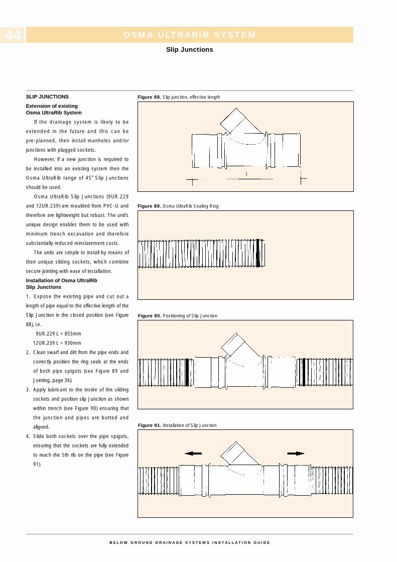
SLIP JUNCTIONS
Extension of existingOsma UltraRib System
If the drainage system is l ikely to be
extended in the future and this can be
pre-planned, then install manholes and/or
junctions with plugged sockets.
However, if a new junction is required to
be installed into an existing system then the
Osma UltraRib range of 45˚ Slip Junctions
should be used.
Osma UltraRib Slip Junctions (9UR.229
and 12UR.239) are moulded from PVC-U and
therefore are lightweight but robust. The unit’s
unique design enables them to be used with
minimum trench excavation and therefore
substantially reduced reinstatement costs.
The units are simple to install by means of
their unique sliding sockets, which combine
secure jointing with ease of installation.
Installation of Osma UltraRibSlip Junctions
1. Expose the existing pipe and cut out a
length of pipe equal to the effective length of the
Slip Junction in the closed position (see Figure
88), i.e.
9UR.229 L = 855mm
12UR.239 L = 930mm
2. Clean swarf and dirt from the pipe ends and
correctly position the ring seals at the ends
of both pipe spigots (see Figure 89 and
Jointing, page 36).
3. Apply lubricant to the inside of the sliding
sockets and position slip Junction as shown
within trench (see Figure 90) ensuring that
the junction and pipes are butted and
aligned.
4. Slide both sockets over the pipe spigots,
ensuring that the sockets are fully extended
to reach the 5th rib on the pipe (see Figure
91).
OSMA ULTRARIB SYSTEM
Slip Junctions
Figure 88. Slip junction, effective length
Figure 89. Osma UltraRib Sealing Ring
Figure 90. Positioning of Slip Junction
Figure 91. Installation of Slip Junction
B E L O W G R O U N D D R A I N A G E S Y S T E M S I N S T A L L A T I O N G U I D E
44
L
44
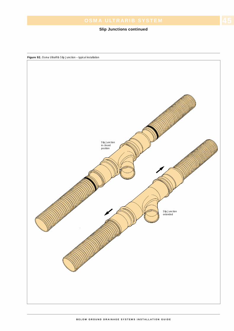
OSMA ULTRARIB SYSTEM
Slip Junctions continued
Figure 92. Osma UltraRib Slip Junction – typical installation
B E L O W G R O U N D D R A I N A G E S Y S T E M S I N S T A L L A T I O N G U I D E
45
Slip Junctionin closedposition
Slip Junctionextended
45
WAVIN TWINWALL SYSTEM
Contents
B E L O W G R O U N D D R A I N A G E S Y S T E M S I N S T A L L A T I O N G U I D E
46
CONTENTS PAGE
Jointing 47
Connections to other materials 48-49
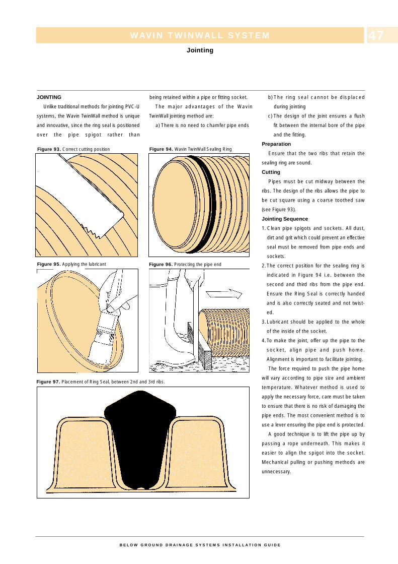
JOINTING
Unlike traditional methods for jointing PVC-U
systems, the Wavin TwinWall method is unique
and innovative, since the ring seal is positioned
over the pipe spigot rather than
being retained within a pipe or fitting socket.
The major advantages of the Wavin
TwinWall jointing method are:
a) There is no need to chamfer pipe ends
b) The r ing seal cannot be displaced
during jointing
c) The design of the joint ensures a flush
fit between the internal bore of the pipe
and the fitting.
Preparation
Ensure that the two ribs that retain the
sealing ring are sound.
Cutting
Pipes must be cut midway between the
ribs. The design of the ribs allows the pipe to
be cut square using a coarse toothed saw
(see Figure 93).
Jointing Sequence
1. Clean pipe spigots and sockets. All dust,
dirt and grit which could prevent an effective
seal must be removed from pipe ends and
sockets.
2.The correct position for the sealing ring is
indicated in Figure 94 i.e. between the
second and third ribs from the pipe end.
Ensure the Ring Seal is correctly handed
and is also correctly seated and not twist-
ed.
3.Lubricant should be applied to the whole
of the inside of the socket.
4.To make the joint, offer up the pipe to the
socket, a l ign pipe and push home.
Alignment is important to facilitate jointing.
The force required to push the pipe home
will vary according to pipe size and ambient
temperature. Whatever method is used to
apply the necessary force, care must be taken
to ensure that there is no risk of damaging the
pipe ends. The most convenient method is to
use a lever ensuring the pipe end is protected.
A good technique is to lift the pipe up by
passing a rope underneath. This makes it
easier to align the spigot into the socket.
Mechanical pulling or pushing methods are
unnecessary.
WAVIN TWINWALL SYSTEM
Jointing
B E L O W G R O U N D D R A I N A G E S Y S T E M S I N S T A L L A T I O N G U I D E
47
Figure 93. Correct cutting position Figure 94. Wavin TwinWall Sealing Ring
Figure 95. Applying the lubricant Figure 96. Protecting the pipe end
Figure 97. Placement of Ring Seal, between 2nd and 3rd ribs.
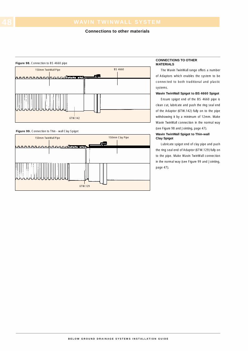
WAVIN TWINWALL SYSTEM
Connections to other materials
B E L O W G R O U N D D R A I N A G E S Y S T E M S I N S T A L L A T I O N G U I D E
48
CONNECTIONS TO OTHERMATERIALS
The Wavin TwinWall range offers a number
of Adaptors which enables the system to be
connected to both traditional and plastic
systems.
Wavin TwinWall Spigot to BS 4660 Spigot
Ensure spigot end of the BS 4660 pipe is
clean cut, lubricate and push the ring seal end
of the Adaptor (6TW.142) fully on to the pipe
withdrawing it by a minimum of 12mm. Make
Wavin TwinWall connection in the normal way
(see Figure 98 and Jointing, page 47).
Wavin TwinWall Spigot to Thin-wallClay Spigot
Lubricate spigot end of clay pipe and push
the ring seal end of Adaptor (6TW.129) fully on
to the pipe. Make Wavin TwinWall connection
in the normal way (see Figure 99 and Jointing,
page 47).
Figure 98. Connection to BS 4660 pipe
Figure 99. Connection to Thin - wall Clay Spigot
150mm TwinWall Pipe
6TW.129
150mm Clay Pipe
6TW.142
150mm TwinWall Pipe BS 4660
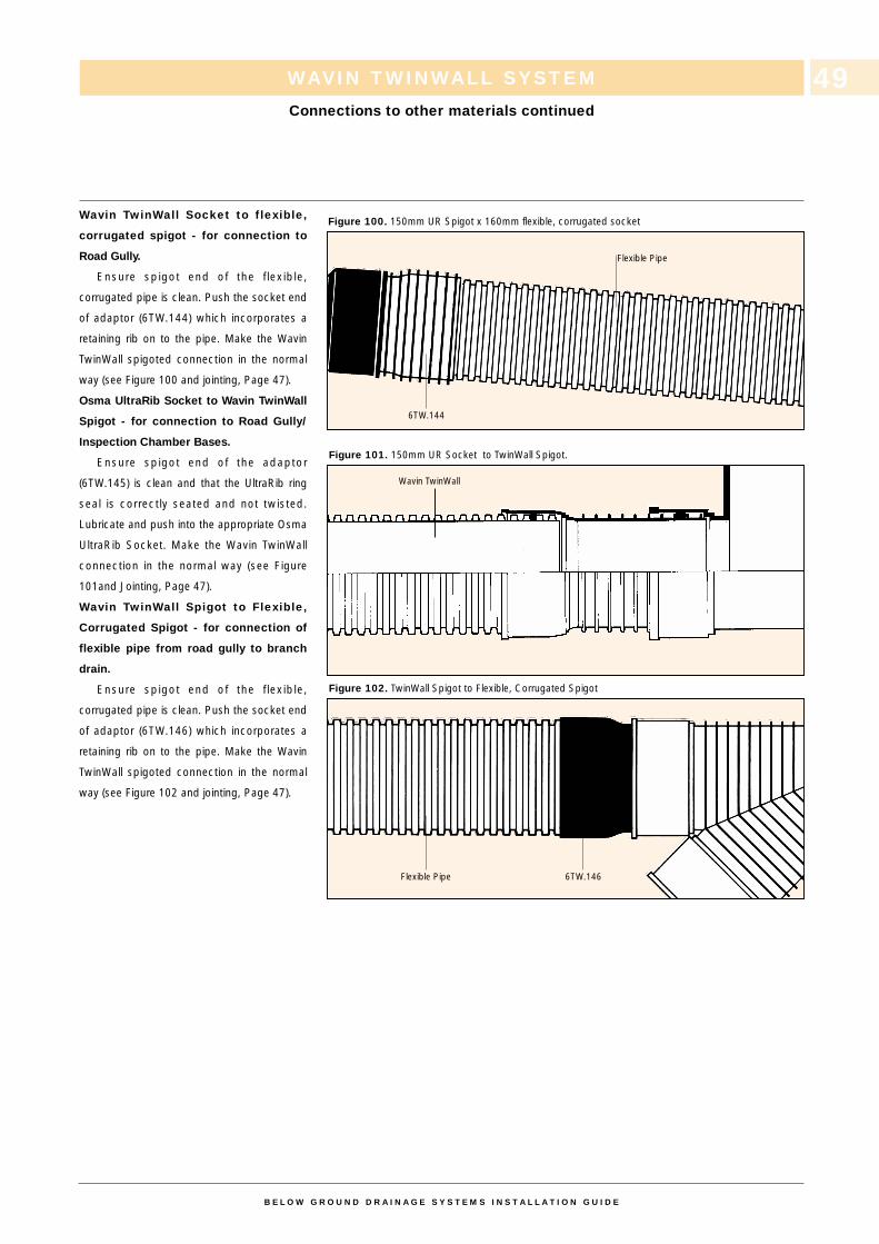
WAVIN TWINWALL SYSTEM
Connections to other materials continued
B E L O W G R O U N D D R A I N A G E S Y S T E M S I N S T A L L A T I O N G U I D E
49
Wavin TwinWall Socket to flexible,
corrugated spigot - for connection to
Road Gully.
Ensure spigot end of the f lexible,
corrugated pipe is clean. Push the socket end
of adaptor (6TW.144) which incorporates a
retaining rib on to the pipe. Make the Wavin
TwinWall spigoted connection in the normal
way (see Figure 100 and jointing, Page 47).
Osma UltraRib Socket to Wavin TwinWall
Spigot - for connection to Road Gully/
Inspection Chamber Bases.
Ensure spigot end of the adaptor
(6TW.145) is clean and that the UltraRib ring
seal is correctly seated and not twisted.
Lubricate and push into the appropriate Osma
UltraRib Socket. Make the Wavin TwinWall
connection in the normal way (see Figure
101and Jointing, Page 47).
Wavin TwinWall Spigot to Flexible,
Corrugated Spigot - for connection of
flexible pipe from road gully to branch
drain.
Ensure spigot end of the f lexible,
corrugated pipe is clean. Push the socket end
of adaptor (6TW.146) which incorporates a
retaining rib on to the pipe. Make the Wavin
TwinWall spigoted connection in the normal
way (see Figure 102 and jointing, Page 47).
Figure 100. 150mm UR Spigot x 160mm flexible, corrugated socket
Figure 101. 150mm UR Socket to TwinWall Spigot.
Figure 102. TwinWall Spigot to Flexible, Corrugated Spigot
Flexible Pipe
6TW.144
Wavin TwinWall
Flexible Pipe 6TW.146
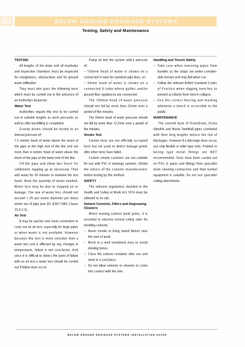
BELOW GROUND DRAINAGE SYSTEMS
Testing, Safety and Maintenance
TESTING
All lengths of the drain and all manholes
and inspection chambers must be inspected
for straightness, obstructions and for ground
water infiltration.
They must also pass the following tests
which must be carried out in the presence of
an Authority’s Inspector.
Water Test
Authorities require this test to be carried
out in suitable lengths as work proceeds as
well as after backfilling is completed.
Gravity drains should be tested to an
internal pressure of:
1.5 metres head of water above the invert of
the pipe at the high end of the line and not
more than 4 metres head of water above the
invert of the pipe at the lower end of the line.
Fi l l the pipe and allow two hours for
settlement, topping up as necessary. Then
add water for 30 minutes to maintain the test
head. Note the quantity of water needed.
Water loss may be due to trapped air or
leakage. The rate of water loss should not
exceed 1 l/h per metre diameter per linear
metre run of pipe (see BS 8301:1985 Clause
25.6.2.3).
Air Test
It may be quicker and more convenient to
carry out an air test, especially for large pipes
or when water is not available. However
because this test is more sensitive than a
water test and is affected by any changes in
temperature, failure is not conclusive. And
since it is difficult to detect the point of failure
with an air test a water test should be carried
out if failure does occur.
Pump air into the system until a pressure
of:
– 100mm head of water is shown on a
connected U-tube for standard pipe lines, or:
– 50mm head of water is shown on a
connected U-tube where gul l ies and/or
ground floor appliances are connected.
The 100mm head of water pressure
should not fall by more than 25mm over a
period of five minutes.
The 50mm head of water pressure should
not fall by more than 12.5mm over a period of
five minutes.
Smoke Test
Smoke tests are not officially accepted
tests but are used to detect leakage points
after other tests have failed.
Certain smoke canisters are not suitable
for use with PVC-U drainage systems. Obtain
the advice of the canister manufacturers
before testing by this method.
SAFETY
The relevant regulations detailed in the
Health and Safety at Work Act 1974 must be
adhered to on site.
Solvent Cements, Fillers and Degreasing Cleaners
When making solvent weld joints, it is
essential to observe normal safety rules for
handling solvents.
– Never smoke or bring naked flames near
the area of work.
– Work in a well ventilated area to avoid
inhaling fumes.
– Close the solvent container after use and
store in a cool place.
– Do not allow solvents or cleaners to come
into contact with the skin.
Handling and Trench Safety
– Take care when removing pipes from
bundles as the straps are under consider-
able tension and may flail when cut.
– Follow the relevant British Standard Codes
of Practice when digging trenches to
prevent accidents from trench collapse.
– Use the correct fencing and marking
whenever a trench is accessible to the
public.
MAINTENANCE
The smooth bore of OsmaDrain, Osma
UltraRib and Wavin TwinWall pipes combined
with their long lengths reduce the risk of
blockages. However if a blockage does occur,
use only flexible or roller type rods. Pointed or
boring type metal f i tt ings are NOT
recommended. Tests have been carried out
on PVC-U pipes and fittings from specialist
drain cleaning contractors and their normal
equipment is suitable. Do not use specialist
cutting attachments.
B E L O W G R O U N D D R A I N A G E S Y S T E M S I N S T A L L A T I O N G U I D E
50
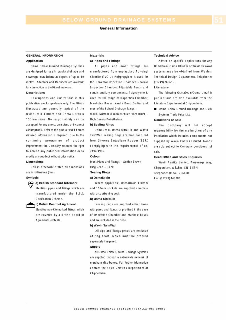
BELOW GROUND DRAINAGE SYSTEMS
General Information
B E L O W G R O U N D D R A I N A G E S Y S T E M S I N S T A L L A T I O N G U I D E
51
GENERAL INFORMATION
Application
Osma Below Ground Drainage systems
are designed for use in gravity drainage and
sewerage installations at depths of up to 10
metres. Adaptors and Reducers are available
for connection to traditional materials.
Descriptions
Descriptions and i l lustrations in this
publication are for guidance only. The fittings
il lustrated are generally typical of the
OsmaDrain 110mm and Osma UltraRib
150mm sizes. No responsibil ity can be
accepted for any errors, omissions or incorrect
assumptions. Refer to the product itself if more
detailed information is required. Due to the
continuing programme of product
improvement the Company reserves the right
to amend any published information or to
modify any product without prior notice.
Dimensions
Unless otherwise stated all dimensions
are in millimetres (mm).
Symbols
a) British Standard Kitemark
Identifies pipes and fittings which are
manufactured under the B.S.I.
Certification Scheme.
b) British Board of Agrément
Identifies non-Kitemarked fittings which
are covered by a British Board of
Agrément Certificate.
Materials
a) Pipes and Fittings
All pipes and most fitt ings are
manufactured from unplastized Polyvinyl
Chloride (PVC-U). Polypropylene is used for
the Universal Inspection Chamber, Shallow
Inspection Chamber, Adjustable Bends and
certain ancillary components. Polyethylene is
used for the range of Inspection Chamber,
Manholes Bases, Yard / Road Gullies and
most of the Subsoil Drainage fittings.
Wavin TwinWall is manufactured from HDPE -
High Density Polyethylene.
b) Sealing Rings
OsmaDrain, Osma UltraRib and Wavin
TwinWall sealing rings are manufactured
from Styrene Butadiene Rubber (SBR)
complying with the requirements of BS
2494:1986.
Colour
Most Pipes and Fittings – Golden Brown
Ring Seals – Black
Sealing Rings
a) OsmaDrain
Where applicable, OsmaDrain 110mm
and 160mm sockets are supplied complete
with a captive ring seal.
b) Osma UltraRib
Sealing rings are supplied either loose
with pipes and fittings or pre-fixed in the case
of Inspection Chamber and Manhole Bases
and are included in the price.
b) Wavin TwinWall
All pipe and fittings prices are exclusive
of r ing seals, which must be ordered
separately if required.
Supply
All Osma Below Ground Drainage Systems
are supplied through a nationwide network of
merchant distributors. For further information
contact the Sales Services Department at
Chippenham.
Technical Advice
Advice on specific applications for any
OsmaDrain, Osma UltraRib or Wavin TwinWall
systems may be obtained from Wavin’s
Technical Design Department. Telephone:
(01249) 766655.
Literature
The following OsmaDrain/Osma UltraRib
publications are also available from the
Literature Department at Chippenham.
■ Osma Below Ground Drainage and Civils
Systems Trade Price List.
Conditions of Sale
The Company wil l not accept
responsibility for the malfunction of any
installation which includes components not
supplied by Wavin Plastics Limited. Goods
are sold subject to Company conditions of
sale.
Head Office and Sales Enquiries
Wavin Plastics Limited, Parsonage Way,
Chippenham, Wiltshire, SN15 5PN
Telephone: (01249) 766600.
Fax: (01249) 443286.
BELOW GROUND DRAINAGE SYSTEMS
Acceptance and Abbreviations
52
B E L O W G R O U N D D R A I N A G E S Y S T E M S I N S T A L L A T I O N G U I D E
ACCEPTANCE
a) British Standards Institution
OsmaDrain below ground drainage
systems comply where applicable
with the requirements of the following British
Standards:
BS EN124:1994 Gully tops and manhole
tops for vehicular and pedestrian areas.
BS 4660:1989 Unplasticized polyvinyl
chloride (PVC-U) pipes and plastics fittings of
nominal size 110mm and 160mm for below
ground gravity drainage and sewerage and/or
BS EN 1401-1.
BS 7158:1989 Plastic inspection chamber for
drains.
BS 4962:1989 Plastic pipes for use as light
duty sub-soil drains.
Osma UltraRib pipes comply with the
requirements of the following Water
Industry Specifications (WIS):
WIS 4-31-05: July 1991: Issue 2
Specifications For Solid Wall Concentric
External Rib-Reinforced UPVC Sewer Pipe.
b) British Board of Agrément
Agrément Certificates have been
awarded to the fol lowing Osma
Below Ground Drainage Systems.
87/1835 OsmaDrain Underground Drainage
System.
90/2563 UltraRib Gravity Drainage and
Sewerage System – 150mm.
91/58 Roads and Bridges
UltraRib Gravity Drainage and Sewerage
System – 150mm.
89/2268 UltraRib Gravity Sewerage System –
225/300mm.
89/46 Roads and Bridges
UltraRib Gravity Sewerage System –
225/300mm.
99/R105 Roads and Bridges Highway
Drainage System.
ABBREVIATIONS
P/E Pipes and Fittings with both ends
plain or with one plain end and
one special end.
S/S Pipes and Fittings with one or
more ring-seal or push-fit sockets,
but always one plain or special
end.
D/S Fittings with ring seal or push-fit
sockets at all ends.
SW/1/2S Fitt ings with half-spigot or
half-socket ends.
S/SW Fittings with one or more ring seal
sockets but always one solvent
socket.
SW/S Fittings with one solvent socket
and one plain or special end.

BELOW GROUND DRAINAGE SYSTEMS
Notes
B E L O W G R O U N D D R A I N A G E S Y S T E M S I N S T A L L A T I O N G U I D E
53

BELOW GROUND DRAINAGE SYSTEMS
Notes
B E L O W G R O U N D D R A I N A G E S Y S T E M S I N S T A L L A T I O N G U I D E
54

WAVIN PLASTICS LIMITED, PARSONAGE WAY, CHIPPENHAM, WILTSHIRE SN15 5PN. TELEPHONE: (01249) 766600. FAX: (01249) 443286.
Printed in England