Embed Size (px)
Citation preview

SPECIAL REPORT
Béla Lipták on safety:
oil & gasProcess control guru and author of the “Instrument and Auto-mation Engineers’ Handbook” Béla Lipták discusses emerging industries aimed at exploiting unconventional fossil fuel deposits. These include drilling for oil and gas deposits under deep oceans, in Alaska or above the Arctic Circle as well as recovery technologies used in shale fracturing and oil sand retorting. These unconventional recovery technologies are more expensive than the traditional ones, and present even more safety risks.
Take advantage of Lipták’s critical view of the oil & gas industry to gain a deep understanding of the dangers inherent in its processes, and consider his thorough and innovative approaches to making sure they do not unnecessarily endanger oil & gas industry employees, their neighbors and the environment.

TABLE OF CONTENTS
www.controlglobal.com
Béla Lipták on safety: oil & gas 2
Controls for scraping of the bottom of the barrel – part 1 3
Controls for scraping of the bottom of the barrel – part 2 (fracking) 7
Controls for scraping of the bottom of the barrel – part 3 12
Controls for drilling oil and gas wells 16
Improving oil and gas well safety 20
Safer fracking through process automation 24
How to automate oil platforms – part 1 29
How to automate oil platforms – part 2 33
Drilling safely in the Arctic Ocean 37
Automation can prevent the next BP spill 41

www.controlglobal.com
Béla Lipták on safety: oil & gas 3
Controls for scraping of the bottom of the barrel – part 1Discussing the emerging new industries that are aiming at exploiting the ‘unconventional’ fossil fuel deposits
By Béla Lipták, PE, Columnist
Here I will discuss the emerging new industries that are aiming at exploiting
the “unconventional” fossil fuel deposits. These include drilling for oil and gas
deposits under the oceans, in Alaska or above the Arctic Circle. The recovery
technologies being used in shale fracturing and oil sand retorting are new and unproved.
These “unconventional” recovery technologies are more expensive than the traditional
ones, and present even more safety risks than the “conventional” technologies.
Yet many energy companies have decided to make immense investments to exploit these
fuel deposits, instead of investing in renewable energy. It seems that this will remain to
be the case for years (possibly decades), and therefore discussing the contributions that
automation and process control can make to improve the safety of these emerging indus-
tries is justified.
Before starting this discussion, let us review the sizes of the global deposits and the rates at
which “conventional” fossil and nuclear (uranium) deposits are being consumed (Table 1).
While the fossil and nuclear industries are using different energy units, the data in Table 1 is
given in zeta joules (ZJ) in order to make them easier to compare.
www.controlglobal.com
Béla Lipták on safety: oil & gas 4
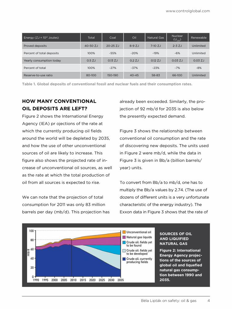
HOW MANY CONVENTIONAL OIL DEPOSITS ARE LEFT?Figure 2 shows the International Energy
Agency (IEA) pr ojections of the rate at
which the currently producing oil fields
around the world will be depleted by 2035,
and how the use of other unconventional
sources of oil are likely to increase. This
figure also shows the projected rate of in-
crease of unconventional oil sources, as well
as the rate at which the total production of
oil from all sources is expected to rise.
We can note that the projection of total
consumption for 2011 was only 83 million
barrels per day (mb/d). This projection has
already been exceeded. Similarly, the pro-
jection of 92 mb/d for 2035 is also below
the presently expected demand.
Figure 3 shows the relationship between
conventional oil consumption and the rate
of discovering new deposits. The units used
in Figure 2 were mb/d, while the data in
Figure 3 is given in Bb/a (billion barrels/
year) units.
To convert from Bb/a to mb/d, one has to
multiply the Bb/a values by 2.74. (The use of
dozens of different units is a very unfortunate
characteristic of the energy industry). The
Exxon data in Figure 3 shows that the rate of
SOURCES OF OIL AND LIQUIFIED NATURAL GAS
Figure 2: International Energy Agency projec-tions of the sources of global oil and liquefied natural gas consump-tion between 1990 and 2035.
Table 1. Global deposits of conventional fossil and nuclear fuels and their consumption rates.
Energy (ZJ = 1021 Joules) Total Coal Oil Natural Gas Nuclear (U235)
Renewable
Proved deposits 40-50 ZJ 20-25 ZJ 8-9 ZJ 7-10 ZJ 2-3 ZJ Unlimited
Percent of total deposits 100% ~55% ~20% ~19% ~6% Unlimited
Yearly consumption today 0.5 ZJ 0.13 ZJ 0.2 ZJ 0.12 ZJ 0.03 ZJ 0.03 ZJ
Percent of total 100% ~27% ~37% ~23% ~7% ~8%
Reserve-to-use ratio 80-100 150-190 40-45 58-83 66-100 Unlimited

www.controlglobal.com
Béla Lipták on safety: oil & gas 5
discovery exceeded the rate of production
until 1980 or so, and since that time, produc-
tion is rising faster than discovery. According
to Figure 3, the rate of discovery today is
about one-quarter of the global production
and will drop to zero by 2050.
The global total of unconventional oil de-
posits (under the ocean, in Alaska, above
the Arctic circle, and in shale or oil sand,
etc.) are estimated to be between 2 and 4
trillion barrels (tb), of which one quarter to
one half is recoverable. If we assume that
the recoverable quantity is 2 tb, at today’s
consumption rate of 92 mb/d (33.5 Bb/yr),
the R/P (reserve/production) ratio for the
unconventional oil reserves is about 59.
CONVENTIONAL AND UNCONVEN-TIONAL NATURAL GAS DEPOSITSNatural gas (NG) can be obtained from both
conventional and unconventional depos-
its (Figure 4). The total global deposits of
conventional NG amount to about 7000 tcf
(trillion cubic feet), while the global con-
sumption in 2010 was about 120 tcf, and is
projected to double by 2035.
Therefore, at today’s rate of consumption,
the global R/P ratio is about 58, while it’s
less at the projected future consumption
rates.
According to the EIA, the size of the total
conventional (non-shale) NG deposit in the
United States in 2009 was 285 tcf, while the
American consumption rate in 2010 was 24
tcf, giving an R/P ratio of 12 at today’s rate
of consumption. This rate is projected to
triple by 2035.
If we consider the unconventional (shale)
deposits, the EIA estimates the “technically
recoverable” amount in the United States as
827-1112 tcf. Some industrial sources esti-
mate it to be 2000 tcf or more. Therefore,
FINDING LESS AND USING MOREFigure 3: Until 1980, dis-covery of new sources of “conventional” oil sources exceeded pro-duction. Since then the yearly amount discoved has fallen below produc-tion, and by 2050 dis-covery of new deposits will fall to zero.

www.controlglobal.com
Béla Lipták on safety: oil & gas 6
using today’s rate of consumption and the
IEA estimate range, the R/P ratio for “un-
conventional” natural gas from fractionable
shale deposits is from 35 to 46.
Today the amount of shale gas and shale oil
that is recoverable by “fracturing” is unre-
solved and is debated. For example, until
2011, the “Marcellus Reserves” (ranging from
Virginia to New York state) were estimated
as more than 400 tcf, while this year the
U.S. Geological Survey reduced that esti-
mate from more than 400 to 84 tcf. Right
now, it seems that “fracking” will continue,
and shale production will increase from the
present 14% of the total U.S. gas production
in 2009 to 45% by 2035. Profit consider-
ations will win over scientific and environ-
mental ones.
I provided the above data, because we
live in an age when the freedom of speech
is interpreted by some as the freedom to
lie. While it is profitable for some to claim
that fossile fuels are plentiful, and that the
present “energy status quo” is sustainable,
I think the readers of this column should
know the scientifically established facts.
WHERE IT’S ATFigure 4: EIA illustration of the locations of the conventional and unconventional (tight sand, shale, coalbed) natural gas deposits.

www.controlglobal.com
Béla Lipták on safety: oil & gas 7
In the United States, natural gas (NG) is the source of about 25% of the total energy
consumption, and shale gas is the source of about 20% of the NG consumed. During
the next years, hydraulic fracturing, or “fracking,” to produce NG will continue to rise,
and will increase from today’s 20% to about 45% of American consumption by 2035. To
date, just in Pennsylvania, there are some 4000 fracking wells in operation, and their num-
ber nationwide is projected to approach 100,000 within a few decades. The size of Ameri-
can recoverable shale gas deposits is debated. Until 2011, industry estimated the Marcellus
Reserves (from Virginia to New York state) to be more than 400 trillion cubic feet (tcf),
while this year the U.S. Geological Survey reduced that estimate to 84 tcf.
THE PROCESSMany of the natural gas wells in the United States use fracking to produce gas at eco-
nomic rates. Large trucks, blenders, tanks and multistage pumps are used to inject mil-
lions of gallons of water at pressures of up to 20,000 psig into these wells that can be
drilled to depths up to 20,000 feet. Hydraulic fracturing can be performed in vertical or
horizontal wells. In horizontal drilling, the terminal drill-hole is completed as a “lateral”
that extends 1,500 to 5,000 feet parallel with the shale layer, while vertical wells extend
only 50 to 300 feet into it. Horizontal drilling also reduces surface disruptions, as fewer
wells are required.
FRACKING
Controls for scraping of the bottom of the barrel – part 2 (fracking)Proponents believe fracking gas could meet U.S. energy needs for a century. Opponents say the NG supply will be exhausted in just a few decades
By Béla Lipták, PE, Columnist

www.controlglobal.com
Béla Lipták on safety: oil & gas 8
After drilling the well, high-pressure liquids
are injected into the shale rock or coal beds
(Figure 1). When the “down-hole” pressure
exceeds the fracture strength of the rock,
it cracks, and the fracture fluid (FF) travels
farther into the rock, extending the crack.
After cracks are formed, they have to be
kept open. Proppants are solid particulates,
such as grains of silica sand, resin-coated
sand or harder materials such as ceram-
ics. They serve to prevent the reclosing of
the fractures when the injection phase is
completed.
In the FF, sometimes, naturally radioac-
tive minerals are also used in order to help
measure the depth of the fractures along
HOW FRACKING WORKSFigure 1. As the fracking fluids (FF) crack the stone, the natural gas (NG) escapes through the frac-tures and travels up the well.

www.controlglobal.com
Béla Lipták on safety: oil & gas 9
the wellbore. Ninety-nine percent of the FF
is usually water, while the rest consists of
chemical additives used to protect the well
and improve its operation. Initially, the in-
jected FF is acidic to increase permeability.
This phase is followed by injecting FF-con-
taining proppants with gradually increased
size solids, and the operation is completed
by flushing the well with water.
When the fracking phase is over, most of
the FF and drill cuttings are processed
for reuse, trucked away, treated on-site
before being released into the environ-
ment or stored on-site either in large
tanks or in “frack ponds” that are several
acres in size. Since these ponds are on the
surface, and their wastewater can con-
taminate ground waters, wells and rivers,
these ponds are sealed with plastic lining.
Usually 30% to 40% of the FF can not be
removed from the underground fractures
and stays down in the shale, creating
small and often toxic lakes.
During the removal of the FF, large
amounts of NG, including methane, escape
from the well or dissolve in the FF and
enter the frack pond. After the removal of
as much FF as possible, the actual pro-
duction starts, and the drilling equipment
is moved to drill another well.
ARGUMENTS PRO AND CONSome representatives of the gas indus-
try and some politicians believe that the
amount of recoverable fracking gas could
meet the American energy needs for a
century or more, while opponents argue
that the NG that is recoverable will be
exhausted in a few decades. Proponents
argue that fracking creates jobs and re-
duces energy imports, while opponents
argue that these jobs are temporary, and
more permanent jobs could be created if
the same investment was made in renew-
able energy.
Industry representatives also argue that
NG is inexpensive, while opponents say
that the cost would be much higher if
the value of the water used, reduced real
estate values, increased mortgage costs,
expenses associated with health effects,
“Usually 30% to 40% of the FF can not be
removed from the underground fractures
and stays down in the shale, creating small
and often toxic lakes.”

www.controlglobal.com
Béla Lipták on safety: oil & gas 10
the cost of wastewater treatment and
legal expenses were included.
The gas industry advertises NG as the
cleanest fossil fuel. Opponents claim that
during the lifetime of a well, 3% to 8% of
the produced methane is leaked into the
atmosphere and, because methane is such
a potent greenhouse gas, the greenhouse-
gas footprint of NG is worse than that of
coal or oil. The tradeoff is that, while the
burning of NG releases fewer allergy- and
cancer-causing solids and other pollutants
than coal, the released methane con-
tributes several times more greenhouse
gases.
Proponents argue that the forces gener-
ated by fracking are insufficient to cause
earthquakes, even when applied to un-
stable geological formations. Opponents
point to the tremors and small earth-
quakes that have already been caused
and to the potential damage to buildings.
Last year, nine quakes occurred, unclamp-
ing ancient faults (geophones) near the
Mahoning River in Ohio and others were
reported in Arkansas and Colorado.
Proponents also argue that the drilling of
wells should not affect the real estate val-
ues and should not invalidate mortgages.
Opponents argue that this is a new indus-
try, and its costs of operation will change
if, in the future, businesses are required
to compensate the landowners for water
contamination or damage to livestock and
crops. They also point to cases such as the
Ohio bank warning the state’s lawmakers
in September 2011 that if the borrowers do
not obtain the consent of the bank before
signing drilling leases, they will be violat-
ing the terms of their mortgage.
ENVIRONMENTAL AND HEALTH CONCERNSIn 2005, Congress passed legislation
prohibiting the federal government from
“The tradeoff is that, while the burning of NG
releases fewer allergy- and cancer-causing
solids and other pollutants than coal, the
released methane contributes several times
more greenhouse gases.”

www.controlglobal.com
Béla Lipták on safety: oil & gas 11
regulating fracking under the Safe Drink-
ing Water Act. This federal legislation is
still in effect; therefore, companies do not
have to disclose what chemicals they are
putting into the ground, although some
states, such as Wyoming, do require it. It
is generally not known which company is
using what chemicals, but in general the
following are used: heavy metals, salts
(bromides, chlorides), acetone, radionu-
clides (strontium, barium), arsenic and
volatile substances (methane, benzene,
alcohol, toluene, phenol, ethylene glycol).
These substances can enter the ground
waters from leaking plastic transfer piping
or due to damage to plastic liners of the
frack ponds.
The industry claims that fracking and
water contamination have never been
undoubtedly linked. Yet, in a 2011 report,
MIT scientists found that “there is evi-
dence of natural gas migration into fresh-
water zones in some areas, most likely as
a result of substandard well completion
practices by a few operators.” Also, there
are additional environmental challenges,
particularly the effective disposal of frac-
ture fluids.
According to the industry, the harmful ef-
fects of fracking are no worse than those
of conventional drilling. Opponents point
to environmental effects, including the
contamination of water supplies, air pol-
lution, migration of gases and fracturing
chemicals to the surface or the potential
mishandling of toxic waste. They point to
cases in Pennsylvania, where farmhouses
and homes were abandoned because of
animals dying, people getting blisters,
dizziness, nosebleeds, etc., from the toxic
and carcinogenic chemicals (New York
Times Magazine, Jan. 20, 2011) and the
class action lawsuits by landowners in
Pennsylvania, Oklahoma, Texas, Wyoming
and Virginia (New York Times, Dec. 2 and
Dec. 9, 2011).
The National Academy of Sciences deter-
mined in 2011 that groundwater contains
much higher concentrations of methane
near fracking wells, causing potential
explosion hazards. In Dimock, Penn., 13
water wells were contaminated with meth-
ane, and Cabot Oil & Gas had to compen-
sate residents financially and construct
a pipeline to bring in clean water to the
town. Elsewhere the landowners had to in-
stall water purifiers or drink bottled water.
In Pennsylvania, the fracking fluid at 116
of 179 deep gas wells contained materials
with high levels of radiation, and in March
2010, Congress directed the EPA to ex-
amine claims of water pollution related to
hydraulic fracturing.

www.controlglobal.com
Béla Lipták on safety: oil & gas 12
In this article, I will concentrate on pipelining safety and on how automation could have
prevented such accidents as the rupturing of the ExxonMobil pipeline running under the Yel-
lowstone River in Montana last summer.
According to the U.S. Department of Transportation Pipeline and Hazardous Materials
Safety Administration, gas-transmission-line accidents increased 72% from the 1990s to
the 2000s, and are still rising because the distribution network is old. Roughly 60% of gas-
transmission lines in the United States were installed before 1970, and some date back to
the Great Depression in the 1930s.
As we will see—like the Deepwater Horizon or Fukushima practices—the main cause of pipe-
lining accidents is not the lack of availability of the sensors needed to detect unsafe condi-
tions, nor is it the inability to know what needs to be done when unsafe conditions occur.
No, it is the manual nature of all of these operations. In other words, the pipelining opera-
tions are also manually controlled, meaning that the detection of an unsafe condition does
not shut down the pumping or compressor stations automatically (Figure 1).
The main concerns in pipelining safety are mechanical damage, construction flaws, crack-
ing and corrosion of large pipelines. Stress corrosion cracking (SCC) and top-of-the-line
PIPELINES
Controls for scraping of the bottom of the barrel – part 3Liptak discusses pipelining safety and how automation processes can prevent pipelining accidents
By Béla Lipták, PE, Columnist

www.controlglobal.com
Béla Lipták on safety: oil & gas 13
corrosion (TLC), which is caused by drop-
lets of condensed natural gas, are the most
likely natural causes of accidents in gas
pipelines. The progress of these forms of
corrosion and the condition of oil and gas
pipelines must be checked continuously
through the use of in-line inspection (ILI)
instruments. These instruments can test
pipe thickness, roundness, check for cor-
rosion, detect minute leaks and any other
defects along the interior of the pipeline
that may either impede the flow of oil or
gas, or pose a potential safety risk to the
operation.
SMART PIPELINE INSPECTION GAUGES (PIGS)Smart PIGs are intelligent robotic de-
vices that are propelled down pipelines
by the flowing gas or liquid to evaluate
the condition of the pipe’s interior to find
locations of rust, weak seams, coating,
thinning walls, etc. They go where people
can’t, but controlling them can be chal-
lenging because most depend solely on
the pressurized fluid in the pipe for pro-
pulsion, and it’s very difficult to stop a
PIG in specific locations. Most PIGs use
magnetic flux leakage methods of inspec-
tion, but some also depend on ultrasound
or the combination of the two to perform
inspections. Figure 2 illustrates the mag-
netic flux leakage type design.
In this design, a strong magnetic field is
established in the pipe wall using either
magnets, or by injecting electrical current
into the steel (the flux loop in Figure 2). Be-
cause the damaged areas of the pipe can’t
support as much magnetic flux as undam-
aged areas, the magnetic flux leaks out of
the pipe wall at the damaged areas, thereby
identifying their locations. An array of sen-
sors is provided around the circumference
of the PIG to detect the magnetic flux leaks
and identify their locations.
LONG-DISTANCE PIPELININGFigure 1. In long-distance pipelining, safety instrumentation and controls can reduce accident risk. Courtesy of Spectra Energy
MAGNETIC FLUX LEAKAGE SMART INSPECTIONFigure 2: Main components of a magnetic flux leakage type smart inspection PIGCourtesy of the Nondestructive Testing Resource Center

www.controlglobal.com
Béla Lipták on safety: oil & gas 14
PIGs can also operate with ultrasound sen-
sors. These PIG designs are provided with
an array of transducers that emit high-fre-
quency sound pulses perpendicular to the
pipe wall and receive echo signals from
both the inner and outer surface of the
pipe. The tool measures the time interval
between the arrival of the reflected echo
from the inner surface and outer surface
to calculate the wall thickness. The elec-
tromagnetic acoustic transducer (EMAT)
is a combination of the above two designs
and represents a major advance in crack
detection in both oil and gas pipelines.
A third of the 1.3 million miles of natural-gas
pipeline in the United States are “unpig-
gable” because their diameters vary, or the
pipe has sharp bends. Yet as these pipes
age and corrode, the need to inspect them
becomes more urgent.
Recently, PIG designs have been improved
at Carnegie Mellon University, where
Explorer II, a 66-pound, 8-foot-long wire-
less robot was developed that looks like
a series of sausage links (Figure 3). It
twists and turns with ease, and because it
has a drive train, it also allows operators
to precisely control where it starts and
stops, instead of being propelled by the
oil or gas flow, as is the case with previ-
ously discussed PIGs. In addition, the use
of permanent magnets slows down the
movement of the previous PIG designs. In
contrast, Explorer II replaces permanent
magnets with a compact electromagnetic
coil, and thereby eliminates the reduction
of the speed.
On some pipelines it’s easier to use re-
mote visual inspection equipment to
assess the condition of the pipe. Robotic
PIGGING THE “UNPIGGABLE”Figure 3. The design of the new Explorer-II PIG is capable to inspect previously “unpig-gable” pipelines. Courtesy of Carnegie Mellon University
“The main cause of pipeline accidents
is the manual nature of these operations.”

www.controlglobal.com
Béla Lipták on safety: oil & gas 15
crawlers of all shapes and sizes have been
developed to navigate pipes. Typically,
the video signal so obtained is fed to a
truck, where an operator reviews the im-
ages and controls the robot. A recent ad-
vance is to use special paints that change
color if leakage occurs at pipe joints, and
this color change then can be detected
automatically through remote inspection,
including the use of drones.
CONTROLLING THE PIGSILI PIGs go where people can’t, but con-
trolling them requires good process con-
trol because most depend solely on the
pipe’s pressurized fluid for propulsion, and
therefore it is difficult to stop the ILI at
specific points. Good speed control re-
quires the measurement of velocity, drag,
pressure drop and flow. On in-compress-
ible oil service, it’s relatively easy to make
these measurements to control speed. On
incompressible gas service, it is not.
What we would need for automatic veloc-
ity control is a cascade loop, where the
master controller is velocity, and the slave
is a flow controller through a bypass valve
(BPV) in the nose of the ILI (Figure 4).
This valve provides a path for the process
fluid to pass through the core of the ILI, so
that if the PIG speeds up, the BPV opens
up further, and if it slows, it closes a bit.
What makes such a cascade loop interest-
ing is that the flow sensor element and
the control valve in this loop are the same.
The flow is measured by the differential
pressure across the BPV (or the whole
rig), while the control valve whose open-
ing is being manipulated is the BPV itself.
SPEED CONTROL VIA A BYPASS VALVEFigure 4: A 40-in. ILI with the speed-control BPV in the nose shown in its fully open position.Courtesy of GE Energy Oil & Gas Division

www.controlglobal.com
Béla Lipták on safety: oil & gas 16
Controls for drilling oil and gas wellsThe drilling for oil and gas will be with us for some time, the only contribution our profession can make is to improve the safety of these processesBy Béla Lipták, PE, Columnist
As the demand for oil rises in the less-developed parts of the world, so does the
price of it (on a per-calorie basis it is four to six times that of gas or coal), and
therefore, drilling for oil is becoming more and more profitable. (I also see the
effect of this profitability on a personal level, as my son-in-law—the captain on a Shell Oil
ship—is starting exploratory drilling on the outer continental shelf off Alaska’s Arctic coast).
In other words, our collective memories are short. Our hunger for profits has erased the
memory of not only the BP accident, but also of Exxon Valdez, and we do not care about
the future, when the sun will keep coming up, while gas and oil will not.
Since it seems that the drilling for oil and gas will be with us for some time, the only con-
tribution our profession can make is to improve the safety of these processes. We can’t
change such facts as, for example, that in areas where fracking is taking place, the number
of allergy patients tripled, or that an area of ice equal to Europe has already melted in the
North Sea, but we can make the drilling process safer.
Here I will describe how the conversion from the present, largely manual operation of well
drilling, can benefit from automation. The key to the safe operation of the drilling process
is a good understanding of a simple process, the operation of a flow loop in a pressurized
“U-tube.” The drilling fluid that is circulated in this loop (also called formation fluid or drilling
DRILLING

www.controlglobal.com
Béla Lipták on safety: oil & gas 17
fluid) consists of water and additives. It is
first pumped down into the well through the
inside of a drill pipe, and is directed to return
back up on the outside of the drill pipe in an
annulus (the space between the drill pipe
and the well bore). As the drilling fluid rises
back up and enters the mud tank (Figure
1), it is also bringing up the rock fragments
(cuttings) that the drilling into the rock lay-
ers produces. This circulation continues until
the desired depth is reached.
The rock fragments brought up from the
well are removed by shakers, while the
drilling fluid is returned from the mud tank
to the suction of the mud pump, which
pumps it down again into the well through
the drill pipe. The circulating drilling fluid is
under high pressure (up to a maximum of
about 15,000 psig). The drilling fluid pres-
sure (Pdf) is generated as the sum of the
elevated suction pressure of the mud pump
(because the mud tank is pressurized by
high- pressure nitrogen) and the pressure
added by the variable-speed pump. In an
automated system (most wells now are
drilled under manual control), the pressure
of the drilling fluid (symbolically controlled
by PC in Figure 1) can be kept on setpoint
by modulating the pressure of the nitrogen
blanket on the mud tank.
In operating the drilling process, the critical
control loop is this pressure control (PC)
loop because on the one hand the pressure
of the drilling fluid (Pdf) has to be below
the fracking pressure (Pfr) so that the drill-
ing fluid does not escape, and on the other
hand, it has to be above the bottom hole
pressure (Pb), so that a kick in hydrocarbon
pressure at the bottom of the well does not
result in oil or gas entering the annulus and
THE OIL WELL “U-TUBE”Figure 1: The key to the safe well drilling operation is to keep the drill-ing fluid pressure (Pdf) above the bottom pressure (Pb), but below the fracking pressure of the drilled for-mation (Pfr).

www.controlglobal.com
Béla Lipták on safety: oil & gas 18
possibly even blowing out the drilling fluid.
Because both of these limit pressures (Pfr
and Pb) can change as the drilling advances
through different rock formations that
might contain oil or gas at different pres-
sures, the fluid pressure must be kept within
Pfr and Pb and must respond to these
variations quickly and accurately. Whether
the pressure of the drilling fluid (Pdf) (the
measurement of PC in Figure 1) is within Pfr
and Pb can be determined automatically on
the basis of the in-and-out flows from the
well. Doing this automatically (which gener-
ally is not done), would make well drilling
much safer.
A need for increasing the drilling fluid pres-
sure (Pdf) is indicated if more fluid returns
from the well (FR) than the amount pumped
into it (FR > FC in Figure 1), or if the level
in the mud tank (LC) is rising. These condi-
tions indicate that the Pdf is lower than the
hydrocarbon pressure at the bottom of the
well (Pb) and, therefore, the drilling fluid
pressure (Pdf) must be increased to stop
the hydrocarbons from entering the well.
Inversely, Pdf must be reduced if the flow
of the returning drilling fluid is dropping
substantially (FR < FC), or if the level in the
mud tank is dropping quickly. Small losses
of drilling fluid are normal, as liquid is lost
with the removed rock fragments and due
to normal leaks into the rock formation.
But, when the required injection of make-
up fluid (containing the required chemical
additives) rises in order to keep the level
constant (LC in Figure 1), the pressure Pdf is
too high. Therefore, if the loss is large, that
indicates that Pdf is too high (higher than
the fracking pressure of the formation, Pfr),
and must be reduced. Otherwise this can
cause the complete loss of circulation.
My recommendation for measuring the drill-
ing fluid flows (FC and FR in Figure 1) is to
use Coriolis flowmeters, because they are
accurate, have high rangeability, and can
also detect density, so that one can also
measure (and control) the rock loading of
the returning drilling fluid. Without control,
this loading can vary too much, even if flow
and pressure are kept constant, because of
the changing nature of the rock formation
being drilled.
The velocity of the drilling fluid at the drill
bit has to be high enough to carry up the
rock fragments through the annulus. This
velocity can be automatically changed by
adjusting the flowing volume (controlled
by FC in Figure 1, which throttles the pump
speed). The two control loops (PC and FC)
interact because a change in pump speed
changes both the flow rate and the dis-
charge pressure of the pump. Therefore,
decoupling of these loops is needed. The al-
gorithm for decoupling the fast FC and the
slow PC control loops is not shown in detail
in Figure 1, only implied by block D.

www.controlglobal.com
Béla Lipták on safety: oil & gas 19
In addition to safely controlling the drilling
fluid flows, pressures, rock loading and mud
tank level, it is also important to accurately
measure the drilling and coring param-
eters near the bit during the drilling opera-
tion (Figure 2). These parameters can be
measured by the drilling sensor sub (DSS),
which then helps to improve down-hole tool
performance.
The DSS sensors measure weight on bit,
torque on bit, annulus and internal pres-
sures and temperatures. The data is col-
lected as a function of time by the down-
hole electronics, and is stored in its memory
until the bottom-hole assembly (BHA) is
retrieved. The DSS has an 8.25-in. outer
diameter, while its inner diameter is 4.125
inches, accommodating the drill string used
in the retrieval of the core.
The sensors, data acquisition electronics
and lithium batteries needed for about 100
hours of operation are packaged in the DSS
sub wall. The sensor data is collected by the
down-hole electronics, and stored in mem-
ory until the bit and BHA are retrieved at
the end of the coring run. At that point, the
data is downloaded, evaluated and used to
improve the operation of the next run.
SENSORS FOR OIL WELLSFigure 2: Battery-operated drilling sensor sub (DSS) sensors measure and memorize the weight on bit, torque on the bit, pressures and temperatures in both the drill pipe and the annulus for the period of a drill run (about 100 hours).Courtesy of the Oild Drilling Program, Texas A&M University.

www.controlglobal.com
Béla Lipták on safety: oil & gas 20
Improving oil and gas well safetyLipták walks us through step-by-step how process control can improve the safety of fracking, off-shore drilling, well blow-out prevention, drilling ship stability and much more
By Béla Lipták, PE, Columnist
I’ve explained how process control can improve the safety of fracking, off-shore drilling,
well blow-out prevention, drilling ship stability, etc. – specific parts of the overall oil pro-
duction process. Now I will walk through the whole process from beginning to end.
I am not in favor of the staggering investments in these processes, but if we are going to
scrape the bottom of the fossil fuel barrel, at least we should do it safely.
THE OVERALL PROCESSOnce the test wells identify the depths at which the oil/gas bearing zones are located, the
operation begins. It consists of three phases: 1) drilling, 2) production and 3) closing or kill-
ing the well. (For a description of killing the well, see Phase 3 at the bottom of this article).
Looking at the equipment used in this process (Figure 1), this industrial process might ap-
pear to be very complex and, therefore, hard to control. In fact it is simple!
The control goal is simply to balance the variable pressure at the bottom of a vertical U-
tube with the pressure of a fluid which is circulated in it. The fluid pressure at the bottom
of the U-tube is adjusted by changing the pump discharge pressures and by changing the
hydrostatic head on the bottom of the U-tube through the adjustment of the density of the
circulated fluid.
DRILLING

www.controlglobal.com
Béla Lipták on safety: oil & gas 21
PHASE 1—DRILLINGPhase 1 starts with drilling the bore hole (~
36 in. dia.) by lowering a drill bit into the
well and rotating it by a shaft inside a verti-
cal drill pipe (~ 6 in. dia.). Through this, pipe
drilling fluid is pumped down, serving the
dual purposes of cooling the bit and carry-
ing up the “cuttings” to the rig through the
annulus (or annular) between the pipe and
the bore hole. As the drilling progresses, a
number of casings are installed for support,
and a number of blow out preventers (BOP)
are added, so that if excessive pressure is
encountered, the well can be closed.
During Phase 1, the goals are:
• To keep the flow velocity and pressure at
the bottom (PB in Figure 2) high enough
to carry the cuttings up. This pressure
ranges from 5000 to 10,000 psig.
• To keep the PB higher than the oil/gas
pressure (PO) in the formation. This safety
margin (ΔP = PB – PO) should be held at
about 500 psig.
• To keep the PB pressure by some 500
psig below the pressure (PF) at which the
drilling fluid would start to escape into the
wall of the borehole by fracturing it (PB <
PF – 500 psig).
• To protect against a “blow-out” that can
occur if high pressure gas pockets are
encountered during drilling.
In order to satisfy the requirements 1), 2)
and 3), all that is needed is to maintain a
pressure balance. This balance must also
consider the hydrostatic heads in the drill
pipe (Hd) and in the annulus (Ha), plus the
friction losses as the drilling fluid moves
through the drill pipe (Fd), the rig and the
annulus (Fa). The hydrostatic heads (H) are
the product of the depth (D) of the well
and the density (r) of drilling fluid (H = Dr),
which in a 10,000-foot well is about 5000
psig. Based on the accurate measurements
DEEP WATER DRILLING
Figure 1. The main components of an offshore oil well and its blow-out preventers (BOP).

www.controlglobal.com
Béla Lipták on safety: oil & gas 22
of these values, the required drill pipe and
annulus pressures (Pdp and Pa) and the
corresponding drill fluid pump suction and
discharge pressures (PS and PD) are easily
calculated as:
Pdp ~ PD = PO + ΔP + Fd – Hd
Pa ~ PS = PO + ΔP – Fa – Ha
Once they are accurately measured, all that
is needed is to satisfy the relationship:
PF > PB = PO + ΔP
In order to satisfy requirement 4) above,
the system also must be able to detect both
the developments of “kicks” and initiate the
response to them. The development can be
detected by noting an increase in the flow
from the well (usually Coriolis meters are
used to measure the flows — F in Figure
2) by the rise in the level in the “mud tank”
(L) and by the rise in the drill pipe and an-
nulus pressures (Pdp and Pa). The critical
measurements, therefore, are the pressures,
densities and flows as shown in Figure 2.
When a “kick” is detected, the pressure bal-
ance must be re-established by doing the
following (in sequence):
• Increase the nitrogen (N2) blanket pres-
sure on the mud tank (Figure 2).
• If that does not stop the “kick,” gradually
close the variable bore ram (Figure 1) in
the BOP and if “soft” closure is desired
(no sudden rise in pressure), throttle the
choke valve (C in Figure 2) while doing it.
• If the “kick pressure” is still rising, first
close the casing ram in the BOP and then
(if needed) the blind shear ram (Figure 1).
PHASE 2—PRODUCTIONDuring the production phase, the pipe that
in Phase 1 was taking the drilling fluid down
into the well serves to carry the oil or gas
up from the formation to the rig. They rise
DRILLING VARIABLESFigure 2: The variables that need to be accu-rately measured in order to safely operate the drilling rig.

www.controlglobal.com
Béla Lipták on safety: oil & gas 23
under their own pressures, so normally
no pump is needed to provide the driving
force. During this phase, the flow direc-
tion is reversed, the fluid properties are
changed (pressures, flows, densities, con-
ductivity), but the process is similar.
The laws of hydraulics through a vertical
U-pipe still describe the process. Therefore,
some of the same sensors that were used
in Phase 1 can also be used, although they
require recalibration and range change.
The oil/gas is collected in storage tanks and
is transported by barges or through pipelines
under the ocean to the shore. During this
phase the required safety controls to protect
against “kicks” are similar to those described
in Phase 1. The fact that the product is flam-
mable requires additional protection to
guarantee safety. If the BOPs failed and the
presence of flammables is detected (Chapter
7.8 of Volume 2 of the Instrument Engineers’
Handbook), the immediate response should
be to turn off all ignition sources on the rig
or start nitrogen purging them. If, in spite of
these steps, fire is detected and can not be
extinguished, the rig should be disconnected
from the well and moved away.
PHASE 3—”KILLING” THE WELLWhen, for any reason, the well is to be
closed (“killed”), killing fluid (usually a
concrete mixture) is pumped into the well
through the kill line shown in the upper
right of Figure 1. As this mix is heavier than
the oil, it displaces the oil and plugs the
well. In this phase too, until the concrete
sets, maintaining the pressure balance is
critical and can be controlled by keeping
the mix density high enough to provide the
required hydrostatic pressure to prevent
blowout. If the concrete is too dilute (low
density), a methane kick can blow it out, as
occurred at the BP accident.
The key to improving safety during all three
phases of the described process is to have
reliable (redundant) sensors and fully auto-
matic response to unsafe conditions so that
time is not wasted by the need for obtaining
management approvals, and mistakes are
not made because operators are untrained
or panicked. It is also important to keep the
operators fully informed of the conditions on
the rig. This requires using “smart annuncia-
tors,” which not only inform them about the
existence of unsafe conditions, but also gives
them instructions on what to do about them.
“If we are going to scrape the bottom of the
fossil fuel barrel, at least we should do it safely.”

www.controlglobal.com
Béla Lipták on safety: oil & gas 24
Safer fracking through process automationAs with so many processes, better automation can lead to better safety
By Béla Lipták, PE, Columnist
Most new industries are first operated under manual control, and only as they ma-
ture do they start applying automatic controls and optimization. Fracking is no
exception, and as it approaches maturity, it also is beginning to take advantage
of automation. In this article, I will discuss some areas where automation could improve the
safety of this industry, including methane recovery and operational reliability.
In the process of fracking, high-pressure water mixed with chemicals and sand is in-
jected into layers of shale rocks deep under ground, which fracture under this pressure
and release the gas and oil they contain. In 2005, Congress passed legislation prohibit-
ing the federal government from regulating this industry and allowing it to not disclose
what chemicals are being injected into the ground. This unregulated operation contin-
ued for a decade because of the argument that these processes were “proprietary,” as
they require unique machinery capable of driving the fluid down more than a mile, and
also require a lot of science to calculate the exact mixtures of water, chemicals and sand
required to crack the tiny fissures in the rock.
After many years, federal regulations are now being introduced, at least for the 100,000 frack-
ing and regular oil and gas wells that are located on public lands. As of now, the states will still
maintain jurisdiction over the wells drilled on private land. We do not accurately know their
FRACKING

www.controlglobal.com
Béla Lipták on safety: oil & gas 25
total number, but we do know that about 1
million unregulated wells have already been
abandoned, and of those some 200,000 have
never even been plugged.
One of the reasons why such large numbers
are abandoned is the high depletion rate
of their production. The “staying power” of
these wells is short. In just the first year of
operation, the production can drop 50%.
Therefore, in order to maintain or increase
the total national production, the drilling of
new wells is needed continuously.
Federal regulations that are just coming
into effect cover several areas of frack-
ing operation where protection of pub-
lic safety is involved. Here and in future
articles, I discuss these areas one at a time
and also describe how process control
and automation can and should be used to
reach these goals. I particularly focus on
the potential of automation for monitor-
ing the types of toxic chemicals and their
Figure 1: An average well, over its lifetime, uses some 5 million gallons (19,000 m3) of water for both fracking and re-fracking. This water contains sand and toxic chemicals and is injected under a pres-sure of up to some 20,000 PSIG (~ 130 bars) at depths of up to 20,000 feet (~ 6 kilometers).
Figure 1aFracking in Wyoming – four oil pads are located on every square kilometer. Courtesy of The Equation
Figure 1bAfter the drilling is completed fracking starts us-ing a number of large number of above ground equipment serving storage, blending and high pressure pumping.

www.controlglobal.com
Béla Lipták on safety: oil & gas 26
escape or leaking into ground and surface
waters.
ARE FRACKING FLUIDS TOXIC?Fracking fluids contain “proppants,” such as
sand, water and a large number of chemicals,
that serve to keep the fractures in the shale
open. In the past, the identity of these chem-
icals was not disclosed by their suppliers like
Halliburton who considered that information
proprietary (Figure 1).
Samples from well blowouts and fluid pits
in Colorado, Wyoming and New Mexico
have shown that the fracking fluids con-
tain more than 100 different kinds of
chemicals, some of them having adverse
side effects including brain damage, birth
defects and cancer. In other locations,
heavy metals, salts (bromides, chlorides),
acetone, radionuclide isotopes (strontium,
barium), arsenic and volatile substances
(methane, benzene, alcohol, toluene,
phenol, ethylene glycol) were found in the
fracking fluids.
Benzene causes cancer and bone marrow
failure; lead damages the nervous system
and causes brain disorders; ethylene gly-
col (antifreeze) can cause death; methanol
is highly toxic; boric acid causes kidney
damage; 2-butoxyethanol causes hemoly-
sis (destruction of blood cells). Whatever
chemicals the fracking fluids contain, they
can end up in the ground water and the
drinking water supplies through ground
penetration or due to leaks in the piping
or in the lining of the “frack ponds.”
We have all heard arguments that “we
“The new federal regulations will require
disclosure of the identity of the fracking
chemicals and the methods used to prevent
their release during fracking, storage in lined
surface pits or disposal in ways such as injection
into dry deep wells, which can and did cause
minor earthquakes.”

www.controlglobal.com
Béla Lipták on safety: oil & gas 27
put a lot worse stuff in our food, our yard
and garden” than the fracking chemicals.
This is true. Yet, we should still be more
careful in protecting our drinking water
supplies. The new federal regulations will
require disclosure of the identity of the
fracking chemicals and the methods used
to prevent their release during fracking,
storage in lined surface pits or disposal in
ways such as injection into dry deep wells,
which can and did cause minor earth-
quakes. Some consider this reinjection
desirable to rebalance the underground
pressures, because without that, ground
movement (minor earthquakes) might
result; others argue that it is this practice
itself that can cause earthquakes.
PROCESS CONTROL CAN INCREASE SAFETYThe potentials of process control are not yet
exploited in the area of water composition
Figure 2aThe equipment used during fracking include a number of chemical trucks. Courtesy of FracFocus.
Figure 2: Fracking fluids contain about 90% water, nearly 10% sand and less then 0.5% of other chemicals, serving the functions that are listed above. Since the total quantity of these fluids is millions of gallons, this 0.5% can represent a substantial quantity of chemicals.

www.controlglobal.com
Béla Lipták on safety: oil & gas 28
monitoring. We do not yet have inexpen-
sive, portable, multivariable, wireless and
smart water composition detectors that
would allow quick measurement and wire-
less transmission of monitoring data. We
do have manual analysis kits (Figure 2) and
portable, smart and multivariable detec-
tors (Figure 3), and we do have wireless
transmitters (See Wireless Control Founda-
tion: Continuous and Discrete Control and
Process Industry by T. Blevins, D. Chen, M.
Nixon and W. Wojszinis, published by ISA),
but we do not have devices that would
combine all these features.
Today the common practice is to pro-
vide a small water analysis laboratory in a
data monitoring truck at the fracking site.
These analysis kits provide the means for
the manual analysis of the composition of
source water, fracturing fluid, flow-back
water, drilling fluids, etc. They can mea-
sure alkalinity, bacteria (iron-related, sul-
fate-reducing, and slime-forming), barium,
boron, chloride, conductivity, hardness
(total as CaCO3), iron (total as Fe), pH,
sulfate, sulfide, silica, chlorine, manganese,
etc., but require not only manual samples,
but also well-trained technicians and
much time to make each analysis.
In the area of inexpensive, multivariable
and automatic monitors/alarms, much
development is needed, although some
progress has been made. For example a
spectrophotometer is available (Figure 4)
which is capable of memorizing up to 25
calibrations and more than 40 pre-pro-
grammed tests. These battery-operated
units provide automatic wavelength selec-
tion and can be carried in small suitcases,
but still require the use of manual samples
in sample tubes.
Figure 4: Smart Spectrophotometer.Courtesy of LeMotte Co.
Figure 3: Hydraulic fracturing water analy-sys kit. Courtesy of Hach Co.

www.controlglobal.com
Béla Lipták on safety: oil & gas 29
How to automate oil platforms – part 1How the oil industry could benefit from better familiarity with automation and process control
By Béla Lipták, PE, Columnist
“Let us explore how the oil industry could benefit from better familiarity with
automation and process control. Here, we’ll focus on the crude oil separation
process, which removes the sand, and splits the crude oil into its three phases
of oil, water and gas. We’ll discuss the control of a single separator (Figure 1) and present
practices in the areas where improvement is needed. We’ll also explore one of the separator
control systems currently in use (Figure 2).
Figure 1 shows the main equipment blocks used in this process. To achieve good separation
and maximize hydrocarbon recovery, it’s usually necessary to use more than one separation
stage and optimize the pressure setpoints at each stage.
The separation process is an interesting one because the crude oil flow, pressure and com-
position all can change quickly and drastically. This in turn can affect the available residence
time needed for good separation. These sudden changes not only can vary the material bal-
ance, but also can change the mist content of the gas, the thickness of the emulsion layer at
the interface between the water and the oil on the inlet side of the separator, and the foam
thickness on the oil outlet side.
Usually, while the first stage of separation removes the sand and some of the gas, the flowrate
and composition of the remaining mixture entering the second stage still varies.
PLATFORMS

www.controlglobal.com
Béla Lipták on safety: oil & gas 30
This variation makes it difficult to prevent
mist carryover on the gas side, vortex forma-
tion on the liquid side and high turbulance
(high velocity) that can prevent good separa-
tion between the oil and water phases and
cause formation of thick emulsion (rag) lay-
ers. Even if the residence time is sufficient for
good separation, a thick emulsion layer can
interfere with good interface detection, and
excessive foaming can cause level measure-
ment errors on the oil end of the separator.
PRESENT PRACTICEOne of the worst—most wasteful and un-
safe—practices that still prevails at some
sites is the use of natural gas instead of
instrument air in pneumatic control sys-
tems. Another, even more widely practiced
characteristic of this industry is manual or
semi-manual control of the process. Fig-
ure 2 shows some examples of this manual
control philosophy, which results in control
loop interactions that are left for the opera-
tors to handle. In addition, one can some-
times find multiple control valves used in
series (LV-2205 and PV-2206 in Figure 2).
Such valves can fight each other and there-
by destabilize the operation.
In the Figure 2 design, there is no automatic
response to the variations in time con-
stants of the process (residence time varies
with load). The bypass flow controller (FIC
throttling FV-2206) and the level control-
ler (LIC throttling LD-2005A) can also fight
each other (and burn up valuable pumping
energy unnecessarily). This is not to say the
present separation controls do not improve
on the earlier, almost fully manual, con-
trol—they do. For example, using split-range
THE CRUDE OIL SEPARATION PROCESSFigure 1: Separation of the multiphase stream into gas, oil and water components typically relies on gravity.

www.controlglobal.com
Béla Lipták on safety: oil & gas 31
control in Figure 2 is a step in the right
direction.
SENSOR AND VALVE SELECTIONFor crude oil applications, control valves
must be carefully selected because they
can be exposed to the effects of severe
flashing, outgassing and the associated
erosion and vibration. Flashing (outgas-
sing) occurs when the outlet pressure falls
below the vapor pressure of the process
fluid. This and the presence of fast-moving
sand particles can cause erosion. One
way to reduce erosion is to use multi-
stage (multi-step) valves, which will split
the pressure reduction into several steps,
thereby more smoothly accommodating
the vapor expansion.
Proper selection of flow and level measure-
ment instruments is also important. Mea-
suring wet natural gas flow is fairly simple
because if the mist is removed and pressure
and temperature compensation are provid-
ed, then both volumetric and mass flows can
be obtained. Naturally, differential pressure
THE WAY WE DO IT NOWFigure 2: The state of the art in separator control leaves room for improvement.Courtesy of Oil and Gas Journal, Firouz Ardeshirian, Mehdi Mansuri, 9-28-1998

www.controlglobal.com
Béla Lipták on safety: oil & gas 32
(ΔP) sensors will provide low accuracy and
rangeability, while Coriolis meters will give
better accuracy and rangeability.
Measuring multiphase crude oil flows is
more difficult. In older installations, indi-
vidual phases of multiphase streams were
either measured only after separation, or
measuring total inflow was attempted using
ΔP sensors (Venturi, V-cone, etc.), which
aren’t suited for erosive, multiphase service,
even if their pressure taps are protected
from plugging by chemical seals with ce-
ramic diaphragms. This isn’t only because
their accuracy and rangeability are low, but
also because the ΔP signal they generate
varies with density, which is a function of
the composition of the flowing mixture.
In more recent crude oil installations, one
can find nuclear densitometers plus pressure
and temperature sensors, which can help cal-
culate the proportion of phases. Also more
recently, some of the clamp-on Doppler
ultrasonic and clamp-on microwave cross-
correlation flowmeters have been used in
applications where low accuracy is accept-
able. These units, being mounted outside the
pipe, are less subject to erosion damage or
plugging than ΔP sensors, but on multiphase
crude oil applications they usually fail be-
cause gas bubbles block the pulses.
The best option is the Coriolis flowmeter.
While no single meter is capable of measur-
ing both total flow and the composition of
multiphase flows, the Coriolis flowmeter
can measure both mass flow and density
of the flowing mixture. Based on these two
measurements (plus pressure and tempera-
ture), the composition of the mixture can
be calculated. Unfortunately, it’s difficult to
maintain flow-tube oscillation when more
than 1-2% gas is present because the gas
induces high and rapidly fluctuating damp-
ing (up to three orders of magnitude higher
than for single-phase conditions), and this
causes the meter to “stall” (fail).
The tasks of level measurements are less
challanging. On the inlet end of the separa-
tor, the water-oil interface can be measured
by magnetostrictive floats or, if one prefers,
external, non-wetted sensors or nuclear
gauges. More recently, instead of attempt-
ing to measure the interface as if it were at a
single level, profile sensors are used. In that
case, the froth layer thickness is also mea-
sured, as the multiple magnetostrictive float
switches or point-sensing nuclear switches
identify the contents of the separator at a
fairly large number of elevation points. On
the oil end of the separator, standard ΔP
level measurement gives acceptable perfor-
mance if the ΔP-cell is protected by extend-
ed diaphragm chemical seals on both sides.

www.controlglobal.com
Béla Lipták on safety: oil & gas 33
How to automate oil platforms – part 2The key to safe operation of an oil well is to maintain the balance between two pressures
By Béla Lipták, PE, Columnist
When I was teaching process control at Yale, we concentrated on one indus-
try at a time. When I started on the controls of nuclear reactors, one student
asked, “What’s the big deal? Aren’t we just boiling water?”
I am reminded of that comment now, starting this second column on automation of oil
platforms. That same kid could probably ask, “What’s the big deal? We’re just controlling a
manometer.”
I like this attitude. It’s important to clearly understand the very basic nature of a process
before getting involved with its many details. Yes, the key to safe operation of an oil well
is to maintain the balance between two pressures—just like between the legs of a manom-
eter—by manipulating the hydrostatic head pressure of one leg to balance the oil and gas
pressure in the well.
I’ve described the crude oil separation process; the measurement and controls required
to separate the oil from water, sand and gas; to properly measure the interfaces, the re-
sponses to production changes; the needs for maintenance; and the operation of several
separators in parallel. Here, I will deal with another phase of this process: the safe auto-
mation of the drilling, production and sealing (closing temporarily or permanently) of
the well.
PLATFORMS

www.controlglobal.com
Béla Lipták on safety: oil & gas 34
DRILLING REQUIRES ATTENTION TO PRESSURESThe drilling process is illustrated in Figure
1. The drilling mud is circulated as it brings
the cuttings to the surface, where they’re
separated from the mud by a centrifuge or
a shale shaker, while the mud is pumped
back down to bring up more cuttings. For
a detailed listing of the equipment used
and for the safety requirements of the
operation, please refer to the OSHA docu-
mentation at www.osha.gov/SLTC/etools/
oilandgas/drilling/drilling.html.
As the drilling progresses, a number of cas-
ings are installed for support, and a number
of blowout preventers (BOP) are
added, so if excessive pressure
is encountered in the formation
(the “manometer” is about to
blow out the drilling liquid), the
well can be closed.
During this drilling phase, the
control goals are to keep the
drilling mud pressure (PMUD) at
the bottom of the well above the
oil/gas pressure (POIL) there,
to protect against a blowout
if high pressure gas or liquid
pockets are encountered. At the
same time, PMUD has to be kept
below the hydraulic fracturing
pressure (PFRACT) at which the
drilling fluid would start to pen-
etrate and escape into the wall
of the bore hole. Therefore, dur-
ing drilling one has to keep the
flow velocity and pressure of the
drilling fluid at the bottom of the
borehole high enough to carry
up the cuttings, keep the PMUD
pressure some 20-25% higher
THE DRILLING PROCESS AND CONTROLSFigure 1: Drilling fluid is pumped down inside the drill pipe, serving the dual purposes of cooling the bit and carrying up the cuttings through the annulus (or annular) between the drill pipe and the bore hole.

www.controlglobal.com
Béla Lipták on safety: oil & gas 35
than the oil/gas pressure (POIL) in the
formation, and keep the drilling fluid pres-
sure (PMUD) below the fracturing pressure
(PFRACT). The control system that will
automatically guarantee this is also shown
in Figure 1.
Here, the automatic drilling controls main-
tain the mud pressure above the oil pres-
sure in the formation by adjusting the pump
speed, the mud density, and (if the mud tank
is pressurized) manipulating the nitrogen
pressure in the vapor space of the tank. If, in
spite of these controls, the pressure of oil in
the formation rises above the mud pressure
(POIL > PMUD) and starts to lift the mud
(thereby suddenly increasing the return-
ing mud flow), or if excessive amounts of
methane are detected in the returning mud,
safety interlocks are activated (ΔPS) to close
the BOPs. In addition, the automatic safety
controls must also be able to detect the de-
velopment of “kicks” and quickly initiate the
response to them. This development can be
detected by noting an increase in the flow
rate from the well. Kicks can also be detect-
ed by the rise in the mud tank level and by
the rise in the annulus pressure.
When the formation of a kick is detected,
the pressure balance of this “manometer”
must be reestablished by: 1) increasing
the nitrogen (N2) blanket pressure on the
mud tank, which will increase the mud
pump suction pressure; 2) increasing the
mud pump discharge pressure by increas-
ing the pump speed; or 3) increasing the
mud density by increasing the flow of
heavy additive. If none of these work, the
automatic safety controls must first close
the blinding ram BOP that closes the an-
nulus, and if the kick pressure is still rising,
must then close the blind shear ram.
Unfortunately, most or none of these
automatic controls are provided in the
operating systems today, and this causes
accidents, like the BP disaster.
WELL SEALING MUST PASS TESTSAfter drilling the well, it’s often temporar-
ily sealed, while production and transpor-
tation-related equipment is installed. (BP
was in the process of sealing when their
accident occurred). This sealing process is
also a “manometer-type,” but here the hy-
drostatic heads that are balancing the oil
“Unfortunately, most or none of these automatic
controls are provided in the operating systems today,
and this causes accidents, like the BP disaster.”

www.controlglobal.com
Béla Lipták on safety: oil & gas 36
pressure (POIL) are generated not only by
mud, but also by cement and sea water.
The most critical step in sealing the well
is testing the integrity of the cement. This
testing involves generating a pressure
differential of about 3,000 psi across the
cement, and checking if any fluid passes
through it in either direction. When the
test pressure (PTEST) is above the oil or
gas pressure in the formation (POIL), the
test is called positive because if the ce-
menting is defective, the liquid will leak
from the well. When the test pressure
(PTEST) is below the oil or gas pressure
in the formation (POIL), the test is called
negative because if the well is not prop-
erly sealed, leakage will be entering the
well (Figure 2).
Both positive and negative tests are per-
formed twice, once measuring flow and
once measuring pressure. When perform-
ing a positive test, PTEST is set at POIL +
3,000 psi, and the first flow test, referred
to as “open test,” is performed (#1 in Fig-
ure 2). During this test, the valve is open,
and if there is in-leakage, the flowmeter
(FI) reads that flow. Then, the next pres-
sure test, called the “closed test,” is per-
formed. In this test, the well is sealed in
(the valve is closed as in #2), and if there
is out-leakage, the pressure in the well
(PI) will drop.
The most important test is the negative
one. PTEST is set at 3,000 psi below the
oil pressure (POIL), and first the open test
is performed (#3 in Figure 2). In this test,
the valve is open, and if there is in-leak-
age, the flowmeter (FI) reads that flow.
Then the closed test is performed (#4),
in which the valve is closed, and if there
is in-leakage, the pressure in the well will
rise. In the case of the BP accident, both
negative tests failed and methane leaked
through the cement, but the crew decided
to go ahead with the sealing anyway. The
consequences we know, and we also know
that simple automation could have saved
11 lives and prevented an environmental
disaster.
THE FOUR TESTSFigure 2: The most critical step in sealing the well is the testing of the integrity of the ce-ment. Pressure differentials of about 3,000 psi in either direction must show no leakage of pressure or flow.

www.controlglobal.com
Béla Lipták on safety: oil & gas 37
Drilling safely in the Arctic OceanLipták shows why full automation could improve the safety of off-shore drilling in and transportation from the Arctic Ocean
By Béla Lipták, PE, Columnist
We’ve explored the safety improvements that automation could make to the
nuclear industry and to oil/gas drilling by replacing their manual mode of op-
eration. Here I am continuing that discussion by showing why full automation
could improve the safety of offshore drilling in and transportation from the Arctic Ocean.
Here, I’ll show what automation can do for oil sand processing/pipelining.
I will not discuss the environmental damage drilling in the Arctic can cause nor the risks to
the crew due to ice and insufficient winterizing. I will only focus on what optimized process
control could do to protect the ships from storms and hurricanes by automatically stabiliz-
ing them while drilling.
Drilling ships have to pass through the Bering strait, which is open only during the summer.
The storms in the Arctic Ocean are powerful. In the past, waves up to 40 feet high and wind
gusts of 89 mph have been reported, and these storms are becoming more powerful as
the planet is warming. Just last December, a Russian drilling ship working near the island of
Sakhalin capsized, and 49 of the crew of 67 were lost.
Therefore, to keep the ship in place is critical. As can be seen in Figure 1, movement would
break the vertical pipes that connect it to the well if the dozen or so anchor rodes (shown
DEEPWATER

www.controlglobal.com
Béla Lipták on safety: oil & gas 38
in Figure 4) were not automatically and
correctly controlled. I will explain why the
present semi-manual methods of stabiliz-
ing are inadequate, and will describe the
automatic optimization strategies that
should replace them.
THE STABILIZATION CONTROL ENVELOPEThe ship is stabilized by a dozen or more
anchor rodes made from chains which are
several miles long (Figure
2) and weigh more than 100
tons. This dynamic stabiliza-
tion allows the ship to move
in three dimensions—to yaw,
pitch, roll and drift—without
breaking the flexible pipes
that connect it to the well.
This is because its position
is held inside a three-dimen-
sional “safe envelope” that
never moves further away
from the well than a safe distance.
The present method of semi-automatic
stabilization is to pull in the rode chains
that are facing the direction of the wind to
increase their “pull,” while “paying out” the
rodes on the opposite side of the ship.
The relationship between the force gener-
ated by this pulling that changes the “rode
catenary” and the push of the storm is well
understood. While the wind force is not
constant, its strength and direction con-
stantly changes, and theoretically it can be
perfectly balanced if the rodes are heavy
enough and if the manipulated winches
(Figure 3) are strong and fast enough. In
other words, what we need to apply is clas-
sic multivariable envelope control (Chapter
8.6 in Volume 2 of the 4th edition of The
Instrument Engineer’s Handbook).
The limits of this envelope are the allowable
A FLOATING CONTROL LOOPFigure 1: The drillships are working in open wa-ter, held in place by winch-operated chain-rodes that act as the “control valves” of this position-control loop.
THE CHAIN GANGFigure 2: The installation of the “control valves,” the several-miles-long chains weighing more than 100 tons (called rodes) require several ships.

www.controlglobal.com
Béla Lipták on safety: oil & gas 39
distances from the well. One method to
implement that control is to use my “Hun-
garian Puli” algorithm. The puli is a livestock
herding dog that keeps the herd together
and moving in the right direction by go-
ing after only one sheep at a time. This is
always the one that is moving in the least
desirable direction (closest to the limit of
the control envelope). So in this application,
we “go after” the rode that is able to pull
the ship away from the closest limit of the
envelope.
The setpoints of this multivariable control
loop are the distances from the borders of
the envelope, and the manipulated vari-
ables (the control valves) are the winches.
It is desirable to put positioners on these
“valves,” which will compare the actual pay-
out lengths and tensions in the rodes with
the required lengths, and will reposition
them if necessary.
The controlled process is the ship, and
the load is the wind force. The dynam-
ics of the process are a function of the
ship’s inertia, response time and speed of
response (process gain = GP). The rode
tension sensor has its own gain (GTS),
and so does the manipulated variable, the
winch (GW). Therefore, in order to prop-
erly control this loop, we must correctly
“size the valve” (make the winch powerful
enough). We also have to select the right
winch gain (GW). It has to provide a fast
enough response, and has to have a vari-
able speed to compensate for the variable
gain (GP) due to the changing load (the
changing force and direction of the wind).
Knowing these gains, we can “tune the
loop” by adjusting the gain of the rode
position controller (GPC), so that the loop
gain (GL) will be about 0.5. {GL = (GP)
(GTS)(GW)(GPC)}.
ADDING FEEDFORWARD TO THE CONTROL ENVELOPEThe strength and the direction of the
force generated by the wind is constantly
changing. Therefore, to stabilize the ship,
the previously described PID tuning by
itself is insufficient. “Anticipation” (feed-
forward) must be added to it. This means
A DELICATE BALANCEFigure 3: The “control valve actuators and positioners” are the winches which can lift more than 100 tons and serve to “throttle” the tension in and catenary of the dozen or so indi-vidual chain-rodes.

www.controlglobal.com
Béla Lipták on safety: oil & gas 40
that we must continuously measure the
dynamics of the wind (the load) and as
soon as it changes, we must start re-
sponding to it (Figure 4).
Naturally, this requires a sophisticated
computer model, which could theoretically
be prepared by scientists (weather scien-
tists, naval architects, etc.), but I would not
do that. I trust Murphy’s Law more than
science. I would simply install a self-teach-
ing artificial neural network (ANN) algo-
rithm model (Chapter 2.16 in Volume 2 of
The Instrument Engineeer’s Handbook) and
let it develop the process model automati-
cally just by watching what is happening in
the real world.
Just as in case of all other new industries,
here too we have to overcome the hurdles
of secrecy and ego. In some corporations
there is a policy of not letting outsiders
“stick their nose” into what they are doing,
and there is also a sense of pride that they
“know better.” These emotional and public
relations hurdles can only be overcome if
our profession proves that it can offer real
benefit to the off-shore drilling industry.
If we could show them that applying the
know-how we have accumulated by auto-
mating the traditional industrial processes
for a century is practical, we could pre-
vent accidents such as Deepwater Horizon
or Sakhalin.
STABLE OPERATIONSFigure 4: The control algorithm that sends the individual setpoints to the winches keeps the ship inside a 3-dimensional safe operating envelope which is “feedforward adjusted” as a function of wind strength and direction. Courtesy of Roy E. Floysvik/Norwegian Petroleum Museum

www.controlglobal.com
Béla Lipták on safety: oil & gas 41
Automation can prevent the next BP spillLipták focuses on the phase during which the accident occurred, which took place during the close of the well
By Béla Lipták, PE, Columnist
After the BP accident in 2010, I described the reasons why the manual operation
contributed to the accident and how automatic safety controls could have pre-
vented it. In other words, I focused on what BP did wrong. In this article I will
concentrate on how to do it right. I will focus only on the phase during which the accident
occurred, which took place during the closing of the well.
Closing serves to plug the casing pipe with a concrete plug strong enough to hold against
the highest formation pressure. To control that, we must keep the plug pressure higher than
that of the formation. Unfortunately, BP did not do that.
BLOWOUT AND THE METHANE “KICK”A blowout occurs if the formation pressure (Pf) suddenly rises because the methane hy-
drate or methane ice (MI) in the formation developed a “kick.” The MI crystal is a solid
similar to ice, except that it traps large amounts of methane within its crystal structure.
The extreme cold and crushing pressure (2200 PSIG at 5000 feet at the ocean bottom and
about 8000 PSIG at the depth of the oil deposits at 15,000 feet) keeps this crystal in the
solid state. If the pressure drops or the temperature rises to the point of phase transition
(PhT), it triggers the MI to suddenly vaporize.
DEEPWATER

www.controlglobal.com
Béla Lipták on safety: oil & gas 42
The temperature of both the conti-
nental and the oceanic crust increases
with depth, reaching values in the
range from about 200 °C (392 ºF) to
400 °C (752 ºF), and the rate of tem-
perature rise is about 30 ºC (about 50
ºF) for every kilometer.
Each cubic foot of MI crystals ex-
plodes into 164 cubic feet of gas.
Therefore, it is wise to avoid drilling
through MI deposits and, if it is done
accidentally, to keep the pressure in-
side the well above and the tempera-
ture below the PhT point. Naturally, to
know where you are during this pro-
cess requires measurements.
Now let us look at the sequence of
events, which started with the ce-
menting of the well. In this case, BP
completed that only 20 hours before
the temporary “killing” of the well
started.
CEMENTINGCementing of the well serves to posi-
tion the production casing pipe firmly
inside the drill hole and to seal the walls
of the drill hole so that oil or gas can enter
the pipe only from the bottom of the well,
but not through the walls. The wellhead
at the Deepwater Horizon well sat on the
ocean floor, nearly a mile from the surface.
The drill hole itself went another 13,000
feet into the rock.
When the drilling is over, the well is full of
drilling mud that was circulating during
the drilling phase. As shown in Figure 1,
the cementing process starts with low-
ering a steel pipe (casing) into the well.
CEMENTING THE WELLFigure 1. The cementing process involves pumping cement, slurry and displacement fluid into the well.

www.controlglobal.com
Béla Lipták on safety: oil & gas 43
After that, the pumping of concrete
and later, the pumping of cement
slurry takes place, followed by the
pumping of displacement fluid. Dur-
ing this operation, two plugs, called
bottom or wiper and top or cement-
ing plugs, are inserted, as shown in
Figure 2.
During cementing, first the bottom
plug is inserted, and the pumped
cement slurry breaks the burst dia-
phragm (rupture disk) in the bottom
plug and, as it rises, it displaces the
drilling mud, pushing it up and out of
the annulus between the casing pipe
and the drill hole.
Once the displacing of the drilling
mud is done and the annulus is full
of the cement slurry, the top plug is
inserted, and it is pushed down by a
displacement fluid that is pumped in
behind it. When it reaches the bot-
tom plug, the job is done, and the
check valve below the bottom float
prevents flow reversal (see detail on
the right of the Figure 2).
In case of the BP accident, the check
valve failed, and because the methane
pressure in the rock formation exceeded
the pressure inside the badly cemented
annulus (the cement had cracks in it), the
methane broke through, and the “blow-
out” of methane and oil followed.
The amount of time it takes for the ce-
ment to harden is called thickening time
or “pumpability time.” For setting and
Figure 2: The main components of the drilling process, including the blowout preventer and the “kill line” below.

www.controlglobal.com
Béla Lipták on safety: oil & gas 44
temporarily sealing wells at depths such
as that of the BP well, under high tem-
perature and pressure, strong cements
are required, and the low-density cement
slurry was not of sufficient quality and
probably contributed to the BP accident.
The cement was of low density because
the contractor mixed in nitrogen to make
the cement slurry more “elastic” and set
faster.
SEALING THE WELLSShortly after the cementing was done,
workers started sealing the well. This is
done by pumping the “killing fluid” (a
concrete mixture) down into the casing
pipe, through the kill line shown in Figure
2. In this phase of the operation, until the
concrete sets, the maintaining of the kill-
ing fluid pressure high enough to always
exceed the formation pressure is essen-
tial, and this pressure can be controlled
by keeping the concrete mix density high
enough to provide the required hydrostat-
ic pressure that prevents the blowout.
Instead, the following occurred at BP. Ce-
menting was completed on April 19, 2010.
The next day, on April 20 at 7 a.m., BP
cancelled the test required to determine
if the bonding of the cement was strong
enough in the annulus, nor did engineers
check the blow-out preventer (BOP) and
just started sealing the well. They were in
a hurry because the crew performing the
sealing was to leave on an 11:15 a.m. flight.
Between that time and the time of the
blowout, some 10 hours passed, dur-
ing which time no corrective action was
taken. After that, at around 9:40 p.m., a
jolt was felt on the bridge followed by the
rig shaking and alarms being activated,
because the most dangerous level of com-
bustible gas intrusion was detected. Yet
electricity was not turned off and at 9:45
p.m. the gas exploded, and oil and con-
crete was blown off the well onto the deck
and ignited. The rest we know.
So what happened? Obviously, the ce-
ment plug was not strong enough to stop
“Around 9:40 p.m., a jolt was felt on the bridge
followed by the rig shaking and alarms being
activated, because the most dangerous level
of combustible gas intrusion was detected.”

www.controlglobal.com
Béla Lipták on safety: oil & gas 45
the oil and gas from blowing out. So was
that predictable and would automation
have prevented it? The answer is a defi-
nite yes! Testing indicated the presence of
a leak somewhere in the well. In spite of
that, because everyone was in a hurry, BP
decided to use a low-density cement plug
and seawater behind it, instead of keeping
the concrete mix density high enough to
provide the required hydrostatic pressure
that would have prevented the blowout.
If this operation were automated, the
balancing pressure required to exceed the
formation pressure would have been auto-
matically calculated and applied. In other
words, the control system would have
kept the hydrostatic pressure high enough
to prevent the gas from entering the well
and would have prevented the use of low-
density cement or sealing fluid.
Therefore, in order to protect against the
repetition of the BP accident, it is essential
to have reliable (redundant) sensors and
fully automatic response to unsafe con-
ditions and mistakes made by either un-
trained operators or by ones willing to cut
corners. This requires using reliable sensors
and “smart annunciators,” which not only
inform the operators about the existence
of unsafe conditions, but either gives them
instructions on what to do about them or,
preferably, automatically does it.
In the case of the BP accident, this would
have not only prevented the application of
the weak concrete plug that allowed the
blowout, but would have also stopped the
whole operation until the blowout preven-
ters were tested and would have automat-
ically disengaged the rig from the well as
soon as fire was detected.
“In order to protect against the repetition
of the BP accident, it is essential to have
reliable (redundant) sensors and fully
automatic response to unsafe conditions and
mistakes made by either untrained operators
or by ones willing to cut corners.”