Embed Size (px)
Citation preview

2017 January– 6 Rev
[email protected] Tel. +31-152-610-900www.lenntech.com Fax. [email protected] Tel. +31-152-610-900www.lenntech.com Fax. +31-152-616-289
Lenntech
8'' END PORT
PRESSURE VESSEL
TECHNICAL
MANUAL

1 Page 2017 yraunaJ – 6 Rev
Introduction
BEL, founded in 1966, specializes in the design and manufacture of a variety of products made from advanced composite materials. With over 40 years of experience, the company has developed and mastered the innovative technologies necessary to manufacture the highest quality composite products. Combining innovation, technology, responsibility and dedication, our goal is to become the leader in providing commercial and industrial composite vessels for our clients needs.
BEL pressure vessels are manufactured from filament wound fiber reinforced plastic (FRP), wound over precision mandrels, using a superior epoxy resin, which results in the ultimate combination of physical strength and an ultra smooth inside surface. Vessels are tested according to the requirements of ASME code section X, the internationally recognized standard for pressure vessel construction.
BEL holds ISO 9001 quality systems certification, and its quality assurance is also approved for in-house final inspection by many of its customers.
The BEL family of pressure vessels is designed to be used as housings for all 4'', 8'', 9'' and 16'' inch spiral-wound Reverse Osmosis (RO), Nanofiltration (NF) and Ultra filtration (UF) membrane elements.
The pressure vessels are manufactured in different configurations, according to the required operating pressures, filtration type, and piping layout. In order to enhance interchangeability and facilitate the use and maintenance of the vessels, the utilization of identical parts and sub-assemblies has been maximized throughout the design of the vessel. For better performance and longer service life, each model is manufactured from the highest quality and highest performing materials of construction.
2 Page 2017 yraunaJ – 6 Rev
Table of contents
1.- SAFETY PRECAUTIONS 3 2.- INSTALLATION NOTES 4 3.- COMPONENT LIST 5 3.1.- BEL8” PRESSURE VESSEL 300 psi END PORT ASSEMBLY. NON CODE 5 3.2.- BEL8” PRESSURE VESSEL 300 psi END PORT ASSEMBLY. CODE 6 3.3.- BEL8” PRESSURE VESSEL 450 psi END PORT ASSEMBLY. CODE & NON CODE 7 3.4.- BEL8” PRESSURE VESSEL 600 psi END PORT ASSEMBLY. CODE & NON CODE 8 3.5.-
3.6.- BEL8” PRESSURE VESSEL 1000 psi END PORT ASSEMBLY. CODE & NON CODE BEL8” PRESSURE VESSEL 1200 psi END PORT ASSEMBLY. CODE & NON CODE
9 10
3.7.- BEL8” PRESSURE VESSEL 1500 psi END PORT ASSEMBLY. CODE & NON CODE 11 4.- MAINTENANCE 12 4.1.- HEAD DISSASEMBLY 13 4.2.- VISUAL INSPECTION 14 4.3.- HEAD REASSEMBLY 15 4.4.- PERMEATE PORT DISASSEMBLY 15 4.5.- PERMEATE PORT REASSEMBLY 16 4.6.- LOADING THE MEMBRANE ELEMENT 18 ANNEX 1 BEL PULLER FOR 8” PRESSURE VESSELS HEADS INSTALLATION 19 BEL PUSHER FOR 8” PRESSURE VESSELS HEADS INSTALLATION 20 ANNEX 2 SHIMMING PROCEDURE 21 ANNEX 3 O-RING REPLACEMENT AND SCRATCHES TREATMENT PROCEDURE 25

3 Page 2017 yraunaJ – 6 Rev
1. Safety Precautions
i. BEL pressure vessels are designed for high pressure operations. Improper installation, operation service or maintenance may cause severe damage to property, physical injury or death.
ii. BEL pressure vessels are designed for water treatment only.
iii. PRESSURE AND TEMPERATURE DESIGN LIMITS - Operation of a vessel outside the design limits
will make void the warranty and may result in vessel fatigue with possible eventual explosive head failure. Although each vessel is tested at 110% of the design pressure LONG-TERM OPERATION ABOVE DESIGN PRESSURE MUST BE PREVENTED . Permeate port pressure MUST NOT EXCEED 125 psi. Vessels should NOT BE CONTINUOUSLY OPERATED AT TEMPERATURES ABOVE 120°. (49° C).
iv. The pressure vessel should not be use as a support. Piping manifolds and other fittings should be
properly designed system framework. OPERATING PERSONNEL SHOULD BE DISCOURAGED FROM APPLYING UNDUE FORCE TO ANY FITTINGS CONNECTED DIRECTLY TO A PRESSURE VESSEL.
v. Only qualified mechanics, experienced in working with high pressure hydraulic systems, should be
allowed to disassemble or assemble the vessel.
vi. Regularly inspect the system so as to ensure that the various components have not deteriorated or been damaged. Replace any faulty component, make sure the reason for the fault has been found and fixed as well.
vii. Make sure that vessels and associated pipe systems are fully depressurized before attempting any
service or maintenance operation.
viii. Be careful not to scratch the inside wall of the shell, especially at the inner sealing area near the groove.
ix. Corroded parts may cause difficulties in removing the head or other components. Do not try to force remove components before all visible signs of corrosion have been eliminated.
x. Never attempt to repair or disassemble the feed/concentrate port in a side port vessel without consulting
BEL.
xi. Inspect end closures regularly; replace components that have deteriorated and correct causes of corrosion.
xii. Do not tolerate Leaks, or allow end closures to be routinely wetted in any way.
xiii. Storage and installation must be done indoor.

4 Page 2017 yraunaJ – 6 Rev
2. Installation notes
i. Provide adequate room for serving at both ends of vessel. Elements are installed from the upstream end, pushed through towards the downstream end and eventually removed from the downstream end.
ii. Make sure that the vessel is horizontally installed on support saddles.
iii. The vessels must not be rigidly clamped in place, mounting design must allow for both radial and axial expansion (typically up to 0.5 mm radial and up to 2-3 mm axial). Restriction can result in damage to the vessel and other system components.
iv. Straps should be tightened enough to hold the vessel onto the support pads, but never so tightly as to restrict expansion.
v. A flexible piping connection should be provided in order to prevent unwanted loads transfer from the manifolds to the permeate connection and to permit decoupling the header from the vessel. The recommended permeate port connection is a U-bend pipe with flexible connections at each end.
vi. The piping system must be connected to the ports using flexible connectors in order to allow relative movement of the vessels and the piping system. (Victaulic or equivalent connections are recommended).
Table 2.1
Max Angle
[Deg]
Max Offset* [mm]
Spacing [mm]- X
End Port
2.5 3 2 + 0.5 1.5"

5 Page 2017 yraunaJ – 6 Rev
3. Component List
NON CODEassembly. 3.1 BEL 8" PRESSURE VESSEL 300 PSI End Port
*-These parts are not shown on the drawing assembly
Table 3.1
Table 3.2
ITEM UDS DESCRIPCION Material Part Number 1 1 Body of Pressure Vessel Glass/Epoxy, acc. F.I.202 8 / 0 / 300 /1-8 2 2 End Port 1.5'' Stainless steel 009-150-0452 3 4 Retaining ring for End Port Stainless steel 55412335 4 2 Seal for End Port EPDM 55412225 5 2 Support ring Engineering plastic 285034015 6 2 Retaining ring (finger hook) Stainless steel 011-801-1202 7 2 Retaining ring for P. Port Stainless steel 283772336 8 2 Base Plate Aluminum 003-861-0600 9 2 Sealing plate Engineering plastic 013-800-1201
10 2 Seal for Sealing Plate Engineering plastic 007-080-0092 11 2 Seal for P. Port EPDM 283776342 12 2 Permeate Port Engineering plastic 008-801-0125 13 2 Seal for Adapter Engineering plastic 285773918 14 1 Thrust ring Engineering plastic 55410419 15 2 Adapter Engineering plastic See Table 3.2 16 2-4 Membrane seal EPDM 55413912 / 55412357 (1.5")
*17 2-3 Saddle Engineering plastic 55410351 *18 2 Strap Assy. Stainless steel 55410310 *19 0-3 Disk spacer - 1mm Engineering plastic 285779231 *20 0-7 Disk spacer - 3mm Engineering plastic 285779233
Part number Part description 001-112-0452 / 285453003 Adapter 1.125" / Adapter 1.125" blind 285349324 / 001-150-0458 Adapter 1.5" / Adapter 1.5'' blind

6 Page 2017 yraunaJ – 6 Rev
VESSEL 300 PSI End Port assembly. CODE3.2 BEL 8" PRESSURE
*-These parts are not shown on the drawing assembl y
Table 3.3
Table 3.4
ITEM UDS DESCRIPCION Material Part Number 1 1 Body of Pressure Vessel Glass/Epoxy, acc. F.I.202 8 / 0 / 300A /1-8 2 2 End Port 1.5'' Stainless steel 009-150-0452 3 4 Retaining ring for End Port Stainless steel 55412335 4 2 Seal for End Port EPDM 55412225 5 2 Support ring Aluminum 285034015 6 2 Retaining ring (finger hook) Stainless steel 011-801-1202 7 2 Retaining ring for P. Port Stainless steel 283772336 8 2 Base Plate Aluminum 003-861-0600 9 2 Sealing plate Engineering plastic 013-800-1201
10 2 Seal for Sealing Plate Engineering plastic 007-080-0092 11 2 Seal for P. Port EPDM 283776342 12 2 Permeate Port Engineering plastic 008-801-0125 13 2 Seal for Adapter Engineering plastic 285773918 14 1 Thrust ring Engineering plastic 55410419 15 2 Adapter Engineering plastic See Table 3.4 16 2-4 Membrane seal EPDM 55413912 / 55412357 (1.5")
*17 2-3 Saddle Engineering plastic 55410351 *18 2 Strap Assy. Stainless steel 55410310 *19 0-3 Disk spacer - 1mm Engineering plastic 285779231 *20 0-7 Disk spacer - 3mm Engineering plastic 285779233
Part number Part description 001-112-0452 / 285453003 Adapter 1.125" / Adapter 1.125" blind 285349324 / 001-150-0458 Adapter 1.5" / Adapter 1.5'' blind

7 Page 2017 yraunaJ – 6 Rev
3.3 BEL 8" PRESSURE VESSEL 450 PSI End Port assembly. CODE & NON CODE
ITEM QTY DESCRIPTION Material Part Number 1 1 Body of Pressure Vessel Glass/Epoxy, acc. F.I.202 8 / 0 / 450-450A /1-8 2 2 End Port 1.5'' Stainless steel 009-150-0452 3 4 Retaining ring for End Port Stainless steel 55412335 4 2 Seal for End Port EPDM 55412225 5 2 Support ring Aluminum 55410299 6 2 Retaining ring (finger hook) Stainless steel 011-801-1202 7 2 Retaining ring for P. Port Stainless steel 283772336 8 2 Base Plate Aluminum 003-861-0600 9 2 Sealing plate Engineering plastic 013-800-1201 10 2 Seal for Sealing Plate Engineering plastic 007-080-0092 11 2 Seal for P.port EPDM 283776342 12 2 Permeate Port Engineering plastic 008-801-0125 13 2 Seal for Adapter Engineering plastic 285773918 14 1 Thrust ring Engineering plastic 55410419 15 2 Adapter Engineering plastic See Table 3.6 16 2-4 Membrane seal EPDM 55413912 / 55412357 (1,5”)
*17 2-3 Saddle Engineering plastic 55410351 *18 2 Strap Assy. Stainless steel 55410310 *19 0-3 Disk spacer - 1mm Engineering plastic 285779231
*-These parts are not shown on the drawing assembly
Table 3.5
Table 3.6
Part number Part description 001-112-0452 / 285453003 Adapter 1.125" / Adapter 1.125" blind 285349324 / 001-150-0458 Adapter 1.5" / Adapter 1.5'' blind

8 Page 2017 yraunaJ – 6 Rev
. CODE & NON CODEBEL 8" PRESSURE VESSEL 600 PSI End Port assembly 43.
ITEM QTY DESCRIPTION Material Part Number 1 1 Body of Pressure Vessel Glass/Epoxy, acc.
F.I.202 8 / 0 / 600-600A /1-8
2 2 End Port 1.5'' Stainless steel 009-150-0602 3 4 Retaining ring for End Port Stainless steel 55412335 4 2 Seal for End Port EPDM 55412225 5 2 Support ring Aluminum 55410299 6 2 Retaining ring (finger hook) Stainless steel 011-801-1202 7 2 Retaining ring for P. Port Stainless steel 283772336 8 2 Base Plate Aluminum 003-861-0600 9 2 Sealing plate Engineering plastic 013-800-1201
10 2 Seal for Sealing Plate Engineering plastic 007-080-0092 11 2 Seal for P. Port EPDM 283776342 12 2 Permeate Port Engineering plastic 008-801-0125 13 2 Seal for Adapter Engineering plastic 285773918 14 1 Thrust ring Engineering plastic 55410419 15 2 Adapter Engineering plastic See Table 3.8 16 4 Membrane seal EPDM 55413912
*17 2-3 Saddle Engineering plastic 55410351 *18 2 Strap Assy. Stainless steel 55410310 *19 0-3 Disk spacer - 1mm Engineering plastic 285779231
*-These parts are not shown on the drawing assembly
Tabla 3.7
Table 3.8
Part number Part description 001-112-1220 / 001-112-1228 Adapter 1.125" / Adapter 1.125" blind

9 Page 2017 yraunaJ – 6 Rev
. CODE & NON CODEBEL 8" PRESSURE VESSEL 1000 PSI End Port assembly 53.
ITEM QTY DESCRIPTION Material Part Number 1 1 Body of Pressure Vessel Glass/Epoxy, acc. F.I.202 8 / 0 / 1000-1000A /1-8 2 2 End Port 1.5'' Super duplex stainless
steel 283153204
3 4 Retaining ring for End Port Stainless steel 55412335 4 2 Seal for End Port EPDM 55412225 5 2 Support ring Aluminum 005-861-1200 6 2 Retaining ring (finger hook) Stainless steel 011-801-1202 7 2 Retaining ring for P. Port Stainless steel 283772336 8 2 Base Plate Aluminum 283154220 9 2 Sealing Plate Engineering plastic 013-800-1201
10 2 Seal for Sealing Plate Engineering plastic 007-080-0092 11 2 Seal for P. Port EPDM 283776342 12 2 Permeate Port Engineering plastic 008-801-0125 13 2 Seal for Adapter Engineering plastic 285773918 14 1 Thrust ring Engineering plastic 55410419 15 2 Adapter Engineering plastic See Table 3.10 16 4 Membrane seal EPDM 55413912
*17 2-3 Saddle Engineering plastic 55410351 *18 2 Strap Assy. Stainless steel 55410310 *19 0-3 Disk spacer - 1mm Engineering plastic 285779231 *20 0-7 Disk spacer - 3mm Engineering plastic 285779233
*-These parts are not shown on the drawing assembly
Table 3.9
Table 3.10
Part number Part description 001-112-1220 / 001-112-1228 Adapter 1.125" / Adapter 1.125" blind

10 Page 2017 yraunaJ – 6 Rev
BEL 8" PRESSURE VESSEL 1200 PSI End Port assembly. CODE & NON CODE 63.
ITEM QTY DESCRIPTION Material Part Number 1 1 Body of Pressure Vessel Glass/Epoxy, acc. F.I.202 8 / 0 / 1200-1200A /1-8 2 2 End Port 1.5'' Super duplex stainless
steel 009-150-1200
3 4 Retaining ring for End Port Stainless steel 55412335 4 2 Seal for End Port EPDM 55412225 5 2 Support ring Aluminum 005-861-1200 6 2 Retaining ring (finger hook) Stainless steel 011-801-1202 7 2 Retaining ring for P. Port Stainless steel 283772336 8 2 Base Plate Aluminum 283154220 9 2 Sealing Plate Engineering plastic 013-800-1201
10 2 Seal for Sealing Plate Engineering plastic 007-080-0092 11 2 Seal for P. Port EPDM 283776342 12 2 Permeate Port Engineering plastic 008-801-0125 13 2 Seal for Adapter Engineering plastic 285773918 14 1 Thrust ring Engineering plastic 55410419 15 2 Adapter Engineering plastic See Table 3.12 16 4 Membrane seal EPDM 55413912
*17 2-3 Saddle Engineering plastic 55410351 *18 2 Strap Assy. Stainless steel 55410310 *19 0-3 Disk spacer - 1mm Engineering plastic 285779231 *20 0-7 Disk spacer - 3mm Engineering plastic 285779233
*-These parts are not shown on the drawing assembly
Table 3.11
Table 3.12
Part number Part description 001-112-1220 / 001-112-1228 Adapter 1.125" / Adapter 1.125" blind

11 Page 2017 yraunaJ – 6 Rev
00 PSI End Port assembly. CODE & NON CODE5BEL 8" PRESSURE VESSEL 1 73.
ITEM QTY DESCRIPTION Material Part Number 1 1 Body of Pressure Vessel Glass/Epoxy, acc. F.I.202 8 / 0 / 1500-1500A /1-8 2 2 End Port 1.5'' Super duplex stainless
steel 009-150-1500
3 4 Retaining ring for End Port Stainless steel 55412335 4 2 Seal for End Port EPDM 55412225 5 2 Support ring Stainless steel 285154226 6 2 Retaining ring (finger hook) Stainless steel 011-801-1202 7 2 Retaining ring for P. Port Stainless steel 283772336 8 2 Base Plate Aluminum 283154220 9 2 Sealing Plate Engineering plastic 013-800-1201
10 2 Seal for Sealing Plate Engineering plastic 007-080-0092 11 2 Seal for P. Port EPDM 283776342 12 2 Permeate Port Engineering plastic 008-801-0125 13 2 Seal for Adapter Engineering plastic 285773918 14 1 Thrust ring Engineering plastic 55410419 15 2 Adapter Engineering plastic See Table 3.12 16 4 Membrane seal EPDM 55413912
*17 2-3 Saddle Engineering plastic 55410351 *18 2 Strap Assy. Stainless steel 55410310 *19 0-3 Disk spacer - 1mm Engineering plastic 285779231 *20 0-7 Disk spacer - 3mm Engineering plastic 285779233
*-These parts are not shown on the drawing assembly
Table 3.13
Table 3.14
Part number Part description 001-112-1220 / 001-112-1228 Adapter 1.125" / Adapter 1.125" blind

12 Page 2017 yraunaJ – 6 Rev
4. Maintenance
4.1 Head disassembly
i. Pressure relieve - Stop all pumps and relieve pressure.
ii. Disconnect all pipes from ports connecting the vessel's heads with the manifolds.
iii. Engage your forefinger in the hook of the retaining ring, lift it up and pull it out of the groove, by running your fingers behind the retaining ring as it continues to exit the groove. As shown in Fig 4-A
Fig 4-A
iv. Remove the three locker segments from the
groove starting from the small segment.
v. head extraction - a - Tight the puller legs (see annex 1) to the vessel wall as shown in Fig 4-B to support the puller to the vessel.
Fig 4-B
b- Screw in fully the cup to the to the Permeate port (clockwise) while supporting the back side of the puller. As shown in Fig 4-C
Fig 4-C
c- Screw out the Puller's handle (counterclockwise) until the Head assembly is extracted, after that pull out the Puller with the Head assembly.

13 Page 2017 yraunaJ – 6 Rev
ection4.2 Visual insp Once the head have been disassembled perform a visual inspection of the vessel head and fittings, to locate any signs of corrosion or salt concentrations if corrosion or salt concentrations are found, follow the following steps:
Component inspection Vessel inspection • Use a small wire brush to loosen any large
deposits. • Place components in a shallow container of
soapy water and scrub their surfaces with medium-grade Scotch-Brite until all corrosion is removed.
• Rinse components with clear water. • Blow components dry with compressed air. • Examine components for damage that may
affect structural strength or sealing properties.
• If any case of deposit of foreign material has been discovered scrub surface with a fine Scotch-Brite and a mild detergent solution, clean both ends of the vessel, up to 20 cm into the vessel.
• If during inspection scratches are found on the inner surface of the vessel up to 20 cm depth, grind the area carefully with sand paper until it is smooth
4.3 Head Reassembly
i. Apply a layer of Lubricant (see 4.5.i) on the O-ring (the amount of the Lubricant should be just enough to give a lustre to the O-ring) and on the bell internal groove.
ii. Place the pusher (see Annex 1) carefully inside the Base Plate Permeate Port as shown in Fig 3-D. To avoid property damage do not bend the tool inside the Base Plate Permeate port.
Fig 4-D
iii. Push the sliding hammer quickly towards the pusher until it strikes the Head assembly to its place as shown in Fig 4-E. To avoid personal injury, always grasp the pusher puller handle with both hands.
Fig 4-E
iv. With the head assembly inserted into the vessel (once the head is in the correct position, the support ring groove is exposed) slide the three segments into the locking groove and Insert the retaining ring as shown in Figs 4-F, 4-G, 3-H.
Fig 4-F
Fig 4-G

14 Page 2017 yraunaJ – 6 Rev
Fig 4-H
v. Insert the retaining ring into the groove of the Support ring and continue running your fingers behind the retaining ring as it continues to enter the groove. As shown in Figs 4-I, 4-J.
Fig 4-I
Fig 4-J

15 Page 2017 yraunaJ – 6 Rev
4.4 Permeate Port disassembly
i. Use a screwdriver in order to remove the retaining ring which holds the Permeate Port to its place As shown in Fig 4-K
Fig 4-K ii. Disassemble the Permeate port from the
Base/Seal Plate by pressing the threaded end of the permeate port as shown in Fig 4-L In case of High pressure vessel (1000-1200 psi) remove the Sealing Plate from the Base plate.
Fig 4-L
iii. Use a screwdriver in order to remove the retaining ring that installed at the inner side of the Base Plate, as shown in Fig 4-M.
Fig 4-N

16 Page 2017 yraunaJ – 6 Rev
eassemblyr4.5 Permeate Port
i. Apply a small amount of lubricant (Molykote 111 or equivalent, Glycerin can be used as well) on the seals Seal for End port, Seal for Permeate Port as shown in Fig 4-O.
Fig 4-O
ii. Install Seals on the base plate and Permeate port for 300-600 psi or on the sealing plate and Permeate port for 1000-1200 psi. Visually check the seals for any mechanical damage. As shown in Fig 4-P.
Fig 4-P
iii. Insert the End port into the Base Plate As shown in Fig 4-Q and install the retaining
ring in the direction of the arrow until it fits the End port groove.
Fig 4- Q
iv. Place the base plate as shown in Fig 4-R and use a screwdriver to install the retaining ring until it fits the End port groove.
Fig 4- R
v. Align the base plate and the End port installed in it with the sealing plate opening, couple both parts by pushing them together until they touch each other as shown in Fig 4-S.

17 Page 2017 yraunaJ – 6 Rev
Fig 4-S
vi. Insert the Permeate port from the inner side of the base plate and carefully push it all the way, as shown in Fig 4-T.
Fig 4-T
vii. Install the retaining ring as shown in Fig 4-U in order to secure the Permeate port to place.
Fig 4-U
viii. Insert the O-ring seal into the groove of the Plate (Base plate at 300-600 psi or sealing plate at 1000-1200 psi) in the direction of the arrow as shown in Fig 4-V Until it fits into the groove.
Fig 4-V
ix. Apply a thin layer of Lubricant (see 4.5.i) on the Adapter seal thereafter insert the Adapter into the Permeate port (with a plastic mallet) as shown in Fig 4-W.
Fig 4-W

18 Page 2017 yraunaJ – 6 Rev
4.6 Loading the membrane element
i. Flush the vessel with fresh water to remove dust and debris.
ii. Install a thrust ring in the downstream of the
vessel.
iii. Insert Head assembly, without the O-ring into the downstream end of the vessel.
iv. Install the segments of the support ring into the
locking groove.
v. Inspect the membrane element surface to find any imperfections that could scratch the vessel bore element loading. If a defect is found, which cannot be easily corrected contact the element manufacturer.
vi. Apply a thin layer of lubricant (see 4.5.i) to
lubricate the inside of the vessel near the groove. This will assist membrane element loading and reduce the risk of inadvertently scratching the vessel bore.
vii. Install the brine seal on the upstream end of the
membrane element so that the seal's open side faces upstream (if it is not already installed by the manufacturer).
viii. Load the first element into the upstream of the
vessel .Leave 10 cm of the element projecting out of the vessel to facilitate connection with the next element.
ix. Apply a small amount of Lubricant (see 4.5.i)
onto the O-ring of the interconnector
and connect the interconnector to the projected end of the loaded element.
x. x. Line up the next element and assemble it to
the inter connector which is already on the first element. Carefully maintain element alignment during assembly, misalignment may result damage to the membrane and vessel parts.
xi. Line up the next element and assemble it to the interconnector which is already on the first element.
xii. Carefully push the two elements into the vessel until the second element is projecting from the vessel approximately 10 cm. Repeat the above steps until all membrane elements have been assembled.
xiii. Calculate the correct shimming distance (see Annex 2) in order to avoid impact damage on the membrane and head parts during pressure drop.
xiv. Insert the shimming spacers on the upstream head assembly (Membrane adapter) so that the sum of their lengths will be equal to the shimming distance.
xv. Install the upstream head assembly as described in section 3.3.
xvi. Remove the downstream head assembly and reassemble it with the O-ring.
`
19 Page 2017 yraunaJ – 6 Rev
Note:
It is highly recommended to replace all seals each time the head is reassembled. A seal replacement kit is available from BEL’s Customer Service.
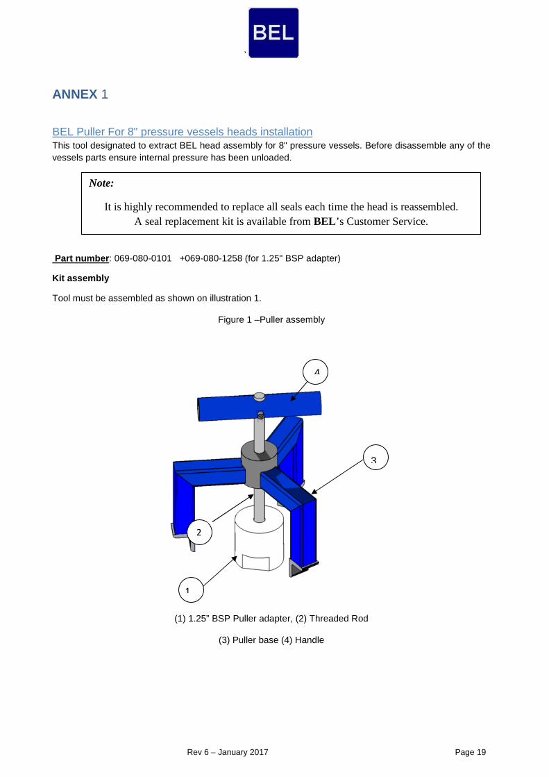
ANNEX 1
pressure vessels heads installationBEL Puller For 8" This tool designated to extract BEL head assembly for 8" pressure vessels. Before disassemble any of the vessels parts ensure internal pressure has been unloaded.
Part number : 069-080-0101 +069-080-1258 (for 1.25" BSP adapter)
Kit assembly
Tool must be assembled as shown on illustration 1.
Figure 1 –Puller assembly
(1) 1.25” BSP Puller adapter, (2) Threaded Rod
(3) Puller base (4) Handle
1
4
3
2

`
20 Page 2017 yraunaJ – 6 Rev
Note:
It is highly recommended to replace all seals each time the head is reassembled. A seal replacement kit is available from BEL’s Customer Service.
BEL Pusher For 8" and pressure vessels heads installation
This tool designated to install BEL head assembly for 8" and pressure vessels.
(Part number : 069-080-0200)
Kit assembly
Tool must be assembled as shown on illustration 1. Ensure tool's handle is located far from the BSP pusher (part 1).
Figure 2 – Pusher-Puller assembly
(1) BSP pusher, (2) Sliding hammer (3) Handles (4) Rod

`
21 Page 2017 yraunaJ – 6 Rev
ANNEX 2
Shimming procedure 1.- CLOSE THE VESSEL ON THE REJECT SIDE AND SET THE THRUST RING IN THE VESSEL (REJECT SIDE)
2.- LOAD THE MEMBRANES FROM FEED SIDE TO REJECT SID E.
3.- REMOVE THE O-RINGS FROM THE ADAPTER (membrane s ide) AND O-RING FROM THE SEALING PLATE OF THE END CAP.
4.- REMOVE THE ADAPTER WITHOUT O-RINGS ( in the membrane side of the adapter) FROM THE END CAP AND RE-INSERT IT AGAIN, PUSHING IT UNTIL TH E EDGE OF THE SEAL FOR ADAPTER REACH THE END CAP HOLE TO PLACE IT.

`
22 Page 2017 yraunaJ – 6 Rev
NOTE 1: KEEP THE ADAPTER O-RING AT THE END CAP SIDE. NOTE 2: APPLY SOME LUBRICANT (GLYCERIN) ON THE ADAPTER O-RING, AT THE END CAP SIDE, AS IT IS SHOWN IN THE NEXT FIGURE.
NOTE 3: DO NOT PUSH THE ADAPTER TOO MUCH INTO THE END CAP HOLE
5.- INSERT THE KIT END CAP – ADAPTER INTO THE VESSE L.

`
23 Page 2017 yraunaJ – 6 Rev
NOTE 4: INSERT THE KIT SLOWLY UNTIL THE POINT "A" BE IN CONTACT WITH POINT "B", AS IT IS SHOWN IN THE ABOVE FIGURE.
6.- AS THE ADAPTER HAS NO O-RING IN THE MEMBRANE SI DE, THE ADAPTER WILL BE PLACED INTO THE MEMBRANE PERMEATE TUBE WITHOUT ANY RESISTA NCE.
NOTE 5: THE ADAPTER WILL KEEP THE SAME POSITION INTO DE END CAP HOLE

`
24 Page 2017 yraunaJ – 6 Rev
7.- KEEP ON PUSHING THE END CAP UNTIL IT REACH ITS FINAL POSITION INTO THE VESSEL.
NOTE 6: IN THE PROCESS OF PUSHING THE ADAPTER WILL MOVE INTO THE END CAP HOLE.
8.- REMOVE THE KIT END CAP – ADAPTER AND MEASSURE T HE DISTANCE " X".
IN ORDER TO AVOID ANY POSSIBLE MISMATCH WITH THE TOLERANCES OF THE PIECES INVOLVED, WE WILL ADD ONE ADDITIONAL 1 mm SHIMMING DISK.
WITH DISK SPACERS " IS THE REAL SPACE TO BE SHIMMEDX+1mmTHE DISTANCE "
11.- REPEAT THE OPERATION WITH EVERY VESSEL TO OBTA IN THE REAL SHIMMING DISTANCE FOR EVERY VESSEL.

`
25 Page 2017 yraunaJ – 6 Rev
ANNEX 3
Ring replacement and scratches treatment procedure-O
1. Preparations
Please prepare the following items before procedure:
i. New intact O-Ring seal suitable with Base/Sealing Plate type.
ii. BEL Base/Sealing Plate. Ensure O-Ring groove is clean and free of scratches.
iii. Clean cloth.
iv. Lubricant.
v. BEL Pusher-Puller (optional).
2. O-Ring Replacement procedure
i. Clean vessel internal surface at sealing area (O-Ring area) with clean damp cloth after the dissembling of the head assembly from the vessel.
ii. Ensure vessel sealing area is smooth and free of scratches. See next procedure for scratch treating.
iii. Assemble Permeate Port Head parts (e.g. Base Plate, Sealing Plate, Adapter, O-Rings and Shims) and apply full and reach layer of lubricant on seals, vessel's groove and vessel's sealing area.
iv. Install Head using BEL's pusher-puller.
3. Scratches treatment procedure
i. Clean vessel internal surface at sealing area (O-Ring area) with clean damp cloth.
ii. Locate the scratch at the O-Ring sealing area. Scratches out of this area will not cause leaks, therefore will not be treated.
iii. Grind out the scratch using Extra-Fine sand paper (P400) until scratch is flat and smooth. DO NOT grind deep into the vessel; this might cause permanent damage to the vessel.
Note: In case of deep scratches or layers delamination please consult BEL engineering department.
[email protected] Tel. +31-152-610-900www.lenntech.com Fax. [email protected] Tel. +31-152-610-900www.lenntech.com Fax. +31-152-616-289
Lenntech