Embed Size (px)
Citation preview

J. Cent. South Univ. (2012) 19: 824−828 DOI: 10.1007/s1177101210782
Modeling and numerical analysis of evaporative condensing regenerator
NIU Runping(牛润萍) 1 , YOU Shijun(由世俊) 2
1. School of Environment and Energy Engineering, Beijing University of Civil Engineering and Architecture, Beijing 100044, China;
2. School of Environmental Science and Technology, Tianjin University, Tianjin 300072, China
© Central South University Press and SpringerVerlag Berlin Heidelberg 2012
Abstract: A twodimensional steady state model was developed and solved numerically to predict the performance of evaporative condensing regenerator. Twodimensional parameter distributions of air, solution and refrigerant were calculated by the mathematical model. The solution content first increases and then decreases along the solution flow direction. At y/Hr=0.98 (where Hr is the height of regenerator), air humidity increases from 1.99% to 2.348% firstly and then decreases. The experimental results were used to validate mathematical model. It is indicated that the simulation results agree with experimental data well. The results not only show that the mathematical model can be used to predict the performance of regenerator, but also has great value in the design and improvement of evaporative condensing regenerator.
Key words: heat and mass transfer; mathematical model; heat of condensation; evaporative condensing regenerator
1 Introduction
Refrigeration and air conditioning are usually carried out using vapour compression systems. A huge amount of electric energy is consumed to achieve both cooling and dehumidification in hot humid areas. In addition, conventional mechanical air conditioners using CFCs as refrigerant cause environmental problem. Also, CFCs contribute to the green house effect which results in global warming and increase in the ambient temperature. Many researchers are motivated to consider the more efficient, sustainable and environmental friendly sources for power generation and air cooling in this situation. Because indoor and outdoor air relative humidity is different, supply air must be dehumidified. For conventional mechanical air conditioners, the supply air must be cooled below its saturation temperature to remove any appreciable amounts of moisture, which may reduce the evaporative temperature and spend more energy. Liquid desiccant system is more attractive to handle latent heat. The weak desiccants can be regenerated using low grade energy, such as fossil fuel, waste heat, and solar energy. Dehumidifiers and regenerators are the main apparatus of liquid desiccant system. In recent year, many researches on numerical
simulation of absorbers and regenerators have been carried out [1−3]. Regenerators can be divided into different categories such as packed bed desiccant regenerators and internally heated desiccant regenerators. LIU and JIANG [4] developed a theoretical model to simulate the heat and mass transfer processes in a cross flow dehumidifier/regenerator using liquid desiccant. The model depends on number of mass transfer unit (NTU) as input parameter, and NTU can be correlated based on the corresponding experimental data. GANDHIDASAN [5] developed a simplified model of a packed bed regeneration process, in which the desiccant solution was heated in two ways. The influence of the heating fluid (water) inlet temperature and the effectiveness of the heating fluidtodesiccant heat exchanger on the performance of the regenerator were studied. A heat and mass transfer performance analysis of an internallycooled liquid desiccant absorber was presented by ARSHAD [6]. The performance prediction model was set up. Other theoretical studies about liquid dehumidification/ regeneration were available in Refs. [7−10].
Liquid desiccant air conditioning system with condensing heat regeneration was presented in this work, which integrated vapour compression refrigeration system and liquid desiccant system. The heat rejected
Foundation item: Project(PHR201007127) supported by Academic Human Resources Development Fund of Institutions of Higher Learning under the Jurisdiction of Beijing Municipality, China; Project(bsbe201005) supported by the Opening Funds of State Key Laboratory of Building Safety and Built Environment, China; Project supported by the Doctoral Startup Foundation of Beijing University of Civil Engineering and Architecture, China
Received date: 2011−07−26; Accepted date: 2011−11−14 Corresponding author: NIU Runping, PhD; Tel: +86−10−68322533; Email: [email protected]

J. Cent. South Univ. (2012) 19: 824−828 825
from the condenser was used to regenerate the liquid desiccant to improve the performance of system and conserve energy. Weak solution was sprayed on the tube bundle of evaporative condenser. Liquid solution was regenerated utilizing evaporation condensation mechanism. The performance of evaporative condensing regenerator was studied.
2 Mathematical model
The schematic diagram of evaporative condensing regenerator is shown in Fig. 1. Desiccant solution is sprayed on the tube bundle from the top of the condenser, forming thin liquid film on the surface of coil. Air flows into the condenser from bottom, together with the solution to form counterflow. Solution comes in direct contact with air. Refrigerant flows in multirow coil. As seen in Fig. 1, air and desiccant solution, as well as the refrigerant, are in a crossflow arrangement. Establishing the coordinate system, air and solution flow in the direction parallel to z axis, while refrigerant flows in the direction parallel to y axis, and the width direction of the condenser is defined as x axis. For the steady flow of solution and air, the parameters of air and liquid desiccant were supposed to be invariable in x direction, so this problem is simplified into a twodimensional problem.
Fig. 1 Schematic diagram of evaporative condensing regenerator
The following assumptions were made to develop the steady state heat and mass transfer model presented in this work [11−12]:
1) Air and solution as well as refrigerant form ideal crossflow with stability;
2) Surface of coil is fully wetted, and heat and mass transfer area is the same;
3) Resistance to heat and mass transfer depends primarily on the gas, and liquid resistance can be ignored;
4) Heat and mass transfer only occurs on plane yz, and occurrence in x direction can be ignored;
5) There is no heat and mass transfer to the surroudings.
Under the above assumptions, heat and mass transfer process in the regenerator can be described in detail by the appropriate governing equations. A model describing heat and mass transfer performance of evaporative condensing regenerator was set up by considering a differential control volume, as shown in Fig. 1. The governing equations are derived on the basis of heat and mass transfer equations and on heat and mass balance equations [13−15].
The mass balance which occurs between the desiccant solution film and the air flow gives following equation:
0 sol a a =
∂ ∂
+ ∂
∂ z m
z w m (1)
where ma is the air mass flow rate, kg/s; msol is the mass flow rate of solution, kg/s; wa is the moisture content of air, kg/kg.
The enthalpy balance on the control volume can be expressed as
z h m
y h m
L H
z m h
∂ ∂
− ∂
∂ =
∂ ∂ a
a r r
r
r sol sol ) ( (2)
where Hr is the height of the regenerator, m; Lr is the length of the regenerator, m; hsol is the specific enthalpy of the solution, kJ/kg; ha is the specific enthalpy of the air, kJ/kg; hr is the specific enthalpy of the refrigerant, kJ/kg.
The moisture transfer between the air and solution can be expressed by
) ( sol a r a
a a a w w L m F
z w
− + ∂
∂ α (3)
where αa is the mass transfer coefficient of air, kg/(m 2 ∙s); wsol is the humidity of air on the surface of solution; Fa is the surface area, m 2 .
The overall heat and mass transfer between the air and liquid desiccant is given by
)] ( ) 1 ( ) [( a sol m , c
a a sa
m , a
a c a w w r c
h h c m F
z h
p p − − + − − =
∂ ∂
α α α ( 4 )
Where αc is the convective heat transfer coefficient, kJ/(kg∙°C); hsa is the specific enthalpy of air on the surface of solution, kJ/kg; cp, m is the specific heat of air at constant pressure, kJ/(kg∙°C).
The heat transfer between refrigerant and solution is given by
) ( r sol r r
r r r t t H m F k
y h
− = ∂ ∂ (5)
where tr is the temperature of refrigerant, °C; tsol is the temperature of solution, °C; kr is the heat transfer coefficient.

J. Cent. South Univ. (2012) 19: 824−828 826
The overall heat and mass transfer between solution and air as well as refrigerant can be expressed by
− − ⋅ = ∂
∂ ) (
r sol r r
r
sol
r r sol t t L H
H m F k
z h
− − + − ) ( ) 1 ( ) ( a sol
m , c
a a sa
r r sol
r r a w w r c
h h L m m F k m
p α α (6)
The boundary conditions are: z=0, ta=ta,in, ha=ha,in, tsol=tsol,in, wsol=wsol,in (7) y=0, tr=tr,in (8)
Equations (2)−(6) are the governing equations of the heat and mass transfer processes in the model. The numerical solutions describing heat and mass transfer performance of air and solution within the regenerator are made up by the differential equations and boundary conditions.
3 Numerical simulation results and discussion
3.1 Mathematical model validation In order to verify the reliability of numerical
solution, it is necessary to test for numerical and experimental results. The inlet and outlet parameters of air and solution are determined. The developed theoretical model is then compared with the experimental results, as shown in Fig. 2 and Fig. 3.
Fig. 2 Comparison of simulation results with experimental data of outlet solution temperature
The calculated temperature of air and the calculated solution content correspond very well to the results of experiments. It is illustrated from Fig. 2 and Fig. 3 that numerical model can be applied in the evaluation and prediction of the heat and mass transfer performance of regenerator.
3.2 Parameter distribution of regenerator Taking the heat and mass transfer coefficients
achieved from experiments and selecting a group of data as the model input parameters, numerical solution
Fig. 3 Comparison of simulation results with experimental data of outlet solution content
according to the model can be calculated, and parameter distributions are shown in Figs. 4−8. The distributions of refrigerant temperature, air temperature, humidity, solution temperature and content inside the regenerator, as well as the outlet parameters are given by the above model, which are important for improving the heat and mass transfer performance of regenerators [16].
The initial conditions are set as follows: ta=33.4 °C, wa=19.9 g/kg, ma=2.28 kg/s, tsol=33 °C, msol=2.18 kg/s, ξsol=22%, tr=48 °C and mr=0.033 kg/s.
Fig. 4 Refrigerant temperature distributions
Figure 4 shows that refrigerant suffers superheated state, two phase state and supercooled state. The temperature of refrigerant falls down from 80 to 48 °C in superheat section. From l/L=0.13, temperature keeps unchanged, entering into two phase section. At l/L=0.85, refrigerant enters into supercooled liquid region, with temperature down by 48 to 44 °C.
As shown in Fig. 5, solution temperature first increases and then drops along z direction from the top to the bottom of the regenerators. At y/Hr=0.98, solution temperature along the z direction increases from 33 °C to the maximum 37.3 °C gradually, and then decreases to
J. Cent. South Univ. (2012) 19: 824−828 827
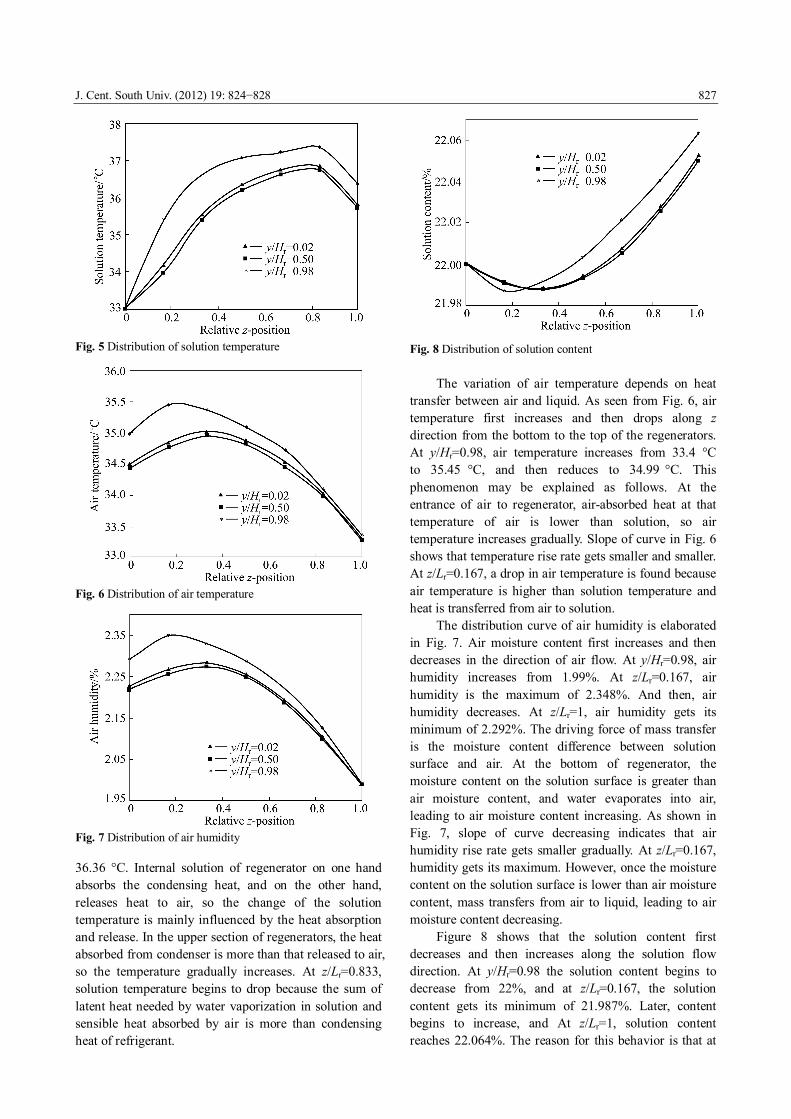
Fig. 5 Distribution of solution temperature
Fig. 6 Distribution of air temperature
Fig. 7 Distribution of air humidity
36.36 °C. Internal solution of regenerator on one hand absorbs the condensing heat, and on the other hand, releases heat to air, so the change of the solution temperature is mainly influenced by the heat absorption and release. In the upper section of regenerators, the heat absorbed from condenser is more than that released to air, so the temperature gradually increases. At z/Lr=0.833, solution temperature begins to drop because the sum of latent heat needed by water vaporization in solution and sensible heat absorbed by air is more than condensing heat of refrigerant.
Fig. 8 Distribution of solution content
The variation of air temperature depends on heat transfer between air and liquid. As seen from Fig. 6, air temperature first increases and then drops along z direction from the bottom to the top of the regenerators. At y/Hr=0.98, air temperature increases from 33.4 °C to 35.45 °C, and then reduces to 34.99 °C. This phenomenon may be explained as follows. At the entrance of air to regenerator, airabsorbed heat at that temperature of air is lower than solution, so air temperature increases gradually. Slope of curve in Fig. 6 shows that temperature rise rate gets smaller and smaller. At z/Lr=0.167, a drop in air temperature is found because air temperature is higher than solution temperature and heat is transferred from air to solution.
The distribution curve of air humidity is elaborated in Fig. 7. Air moisture content first increases and then decreases in the direction of air flow. At y/Hr=0.98, air humidity increases from 1.99%. At z/Lr=0.167, air humidity is the maximum of 2.348%. And then, air humidity decreases. At z/Lr=1, air humidity gets its minimum of 2.292%. The driving force of mass transfer is the moisture content difference between solution surface and air. At the bottom of regenerator, the moisture content on the solution surface is greater than air moisture content, and water evaporates into air, leading to air moisture content increasing. As shown in Fig. 7, slope of curve decreasing indicates that air humidity rise rate gets smaller gradually. At z/Lr=0.167, humidity gets its maximum. However, once the moisture content on the solution surface is lower than air moisture content, mass transfers from air to liquid, leading to air moisture content decreasing.
Figure 8 shows that the solution content first decreases and then increases along the solution flow direction. At y/Hr=0.98 the solution content begins to decrease from 22%, and at z/Lr=0.167, the solution content gets its minimum of 21.987%. Later, content begins to increase, and At z/Lr=1, solution content reaches 22.064%. The reason for this behavior is that at

J. Cent. South Univ. (2012) 19: 824−828 828
the top air moisture content is greater than that of the solution surface and liquid desiccant absorbs water. There is a trend of solution content decreasing. However, once the moisture content on the solution surface is more than that of air, solution content increases for air absorption of water.
4 Conclusions
1) Taking into account threephase process of refrigerant in the evaporative condenser coil, mathematical model describing heat and mass transfer properties of the evaporative condensing regenerator is established, according to the law of conservation of mass and energy. The mathematical models are validated using experimental as well as numerical data. The results show that the model can be used to predict the regenerator performance.
2) Twodimensional parameter distributions of air, solution and refrigerant are calculated by the mathematical model, which is of reference and guiding significance to the performance improvement of regenerator.
References
[1] HWANG Y, REINHARD R, WILLIAM K. An experimental evaluation of a residentialsized evaporatively cooled condenser [J]. International Journal of Refrigeration, 2001, 24: 238−249.
[2] BILAL A. QURESHI S, ZUBAIR M. A comprehensive design and rating study of evaporative coolers and condensers (Part I): Performance evaluation [J]. International Journal of Refrigeration, 2006, 29: 645−658.
[3] ALA H. Performance investigation of plain and finned tube evaporatively cooled heat exchangers [J]. Applied Thermal Engineering, 2003, 23: 325−340.
[4] LIU Xiaohua, JIANG Yi. Heat and mass transfer model of cross flow liquid desiccant air dehumidifier/regenerator [J]. Energy Conversion and Management, 2007, 48: 546−554.
[5] GANDHIDASAN P. Quick performance prediction of liquid desiccant regeneration in a packed bed [J]. Solar Energy, 2005, 79: 47−55.
[6] ARSHAD Y K. Cooling and dehumidification performance analysis of internallycooled liquid desiccant absorbers [J]. Applied Thermal Engineering, 1998, 18: 265−281.
[7] ABDULWAHAB S A, ZURIGAT Y H, ABUARABI M K. Predictions of moisture removal rate and dehumidification effectiveness for structured liquid desiccant air dehumidifier [J]. Energy, 2004, 29: 19−34.
[8] REN Chenqin, JIANG Yi, ZHANG Yianpin. Simplified analysis of coupled heat and mass transfer processes in packed bed liquid desiccantair contact system [J]. Solar Energy, 2006, 80: 121−131.
[9] ANI F N, BADAWI E M, KANNAN K S. The effect of absorber packing height on the performance of a hybrid liquid desiccant system [J]. Renewable Energy, 2005, 30: 2247−2256.
[10] LIU X H, GENG K C, LIN B R. Combined cogeneration and liquiddesiccant system applied in a demonstration building [J]. Energy and Buildings, 2004, 36(9): 945−953.
[11] YIN Yonggao, ZHANG Xiaosong, WANG Geng. Experimental study on a new internally cooled/heated dehumidifier/regenerator of liquid desiccant systems [J]. International Journal of Refrigeration, 2008, 31(5): 857−866.
[12] THOSAPON K, SURAPONG C, KURNAR B S. An experimental study of a solarregenerated liquid desiccant ventilation preconditioning system [J]. Solar Energy, 2009, 83: 920−933.
[13] LOWENSTEIN A. Review of liquid desiccant technology for HVAC applications [J]. HVAC & R Research, 2008, 14(6): 819−839.
[14] LONGO G A, GASPARELLA A. Experimental analysis on desiccant regeneration in a packed column with structured and random packing [J]. Solar Energy, 2009, 83: 511−521.
[15] SULTAN G I, MAHMED A. The effect of inlet parameters on the performance of packed towerregenerator [J]. Renewable Energy, 2002, 26: 271−283.
[16] ESAM E. Performance study on a structured packed liquid desiccant regenerator [J]. Solar Energy, 2006, 80: 1624−1631.
(Edited by YANG Bing)