Embed Size (px)
DESCRIPTION
behaviour of reinforced concrete conical tanks
Citation preview
Western UniversityScholarship@Western
University of Western Ontario - Electronic Thesis and Dissertation Repository
March 2014
Behaviour of Reinforced Concrete Conical Tanksunder Hydrostatic LoadingTareq M. AzabiThe University of Western Ontario
SupervisorDr. Ashraf EL DamattyThe University of Western Ontario
Follow this and additional works at: http://ir.lib.uwo.ca/etdPart of the Construction Engineering and Management Commons, and the Structural
Engineering Commons
This Dissertation/Thesis is brought to you for free and open access by Scholarship@Western. It has been accepted for inclusion in University ofWestern Ontario - Electronic Thesis and Dissertation Repository by an authorized administrator of Scholarship@Western. For more information,please contact [email protected].
Recommended CitationAzabi, Tareq M., "Behaviour of Reinforced Concrete Conical Tanks under Hydrostatic Loading" (2014). University of Western Ontario -Electronic Thesis and Dissertation Repository. Paper 1900.
BEHAVIOUR OF REINFORCED CONCRETE CONICAL TANKS UNDER
HYDROSTATIC LOADING
(Thesis format: Monograph)
By
Tareq M. Azabi
Graduate Program in Engineering Science
Department of Civil and Environmental Engineering
A thesis submitted in partial fulfillment
of the requirements for the degree of
Master of Engineering Science
The School of Graduate and Postdoctoral Studies
Western University
London, Ontario, Canada
February, 2014
© Tareq Azabi 2014
ii
ABSTRACT
Reinforced concrete conical tanks are used in municipalities and industrial applications as
liquid containing vessels. Such tanks can be ground supported tanks or elevated on a
supporting shaft. Although most design codes provide guidelines for rectangular and
cylindrical tanks, no guidance is provided in such codes for conical tanks. Therefore, this
thesis is motivated to study the behaviour and design of this type of tanks. In the current
study, the accuracy of a design approach based on the provisions of Portland Cement
Association (PCA-CCTWP) code for cylindrical tanks combined with an equivalent
cylindrical approach provided by the American Water Works Association AWWA-D100
(2005) is assessed. This assessment is done by comparing the internal forces resulting
from this method with those obtained from a linear finite element analysis model built in-
house. It is noticed that in some of the studied tanks, the PCA-CCTWP approach
combined with the equivalent cylinder method is found to be unsafe. As such, and due to
the complexity of analysing these conical tanks, a simplified design approach in the form
of design charts is provided in this study. This set of charts can be easily used for the
analysis and design of reinforced concrete conical tanks subjected to hydrostatic pressure
and having a constant wall thickness. This approach is developed using the results
obtained from finite element analysis of a wide range of reinforced concrete conical tanks
having different configurations combined with code requirements. This simplified
approach is then utilized to investigate the economics of reinforced concrete conical tanks
versus steel counterparts. A cost analysis is conducted for several conical tanks having
different capacities and different construction materials by including both construction
and life-cycle costs. In addition to the cost analysis, a general study of the effect of tank
dimensions on its cost is illustrated.
KEYWORDS: Conical Tank, Hydrostatic Pressure, Finite Element Analysis, Wall
Thickness, Hoop Tension, Meridional Moment, Meridional Compression, Cost Analysis.

iii
ACKNOWLEDGMENTS
I would like to express my appreciation to my research supervisor, Dr. El Damatty for his
valuable guidance, comments and suggestions, and constructive encouragement
throughout the course of this research. It has been a great privilege and a pleasure to work
under his supervision and to have such a great opportunity to gain from his professional
knowledge.
I would like also to express my appreciation to Dr. Ayman El Ansary for his valuable
advices and comments throughout the analysis process and his contribution to my
research.
My personal involvement with the study would not have been possible without the
financial support of the Libyan Ministry of Higher Education. Also, I would like to thank
all the administrative staff at The Department of Libyan External Scholarship.
Finally, this thesis is dedicated to my wonderful patient wife Manal and my lovely
children; Mohamed, Fatma-Zahraa, and Emadeddin for their love and sacrifices during
the period of my study.
iv
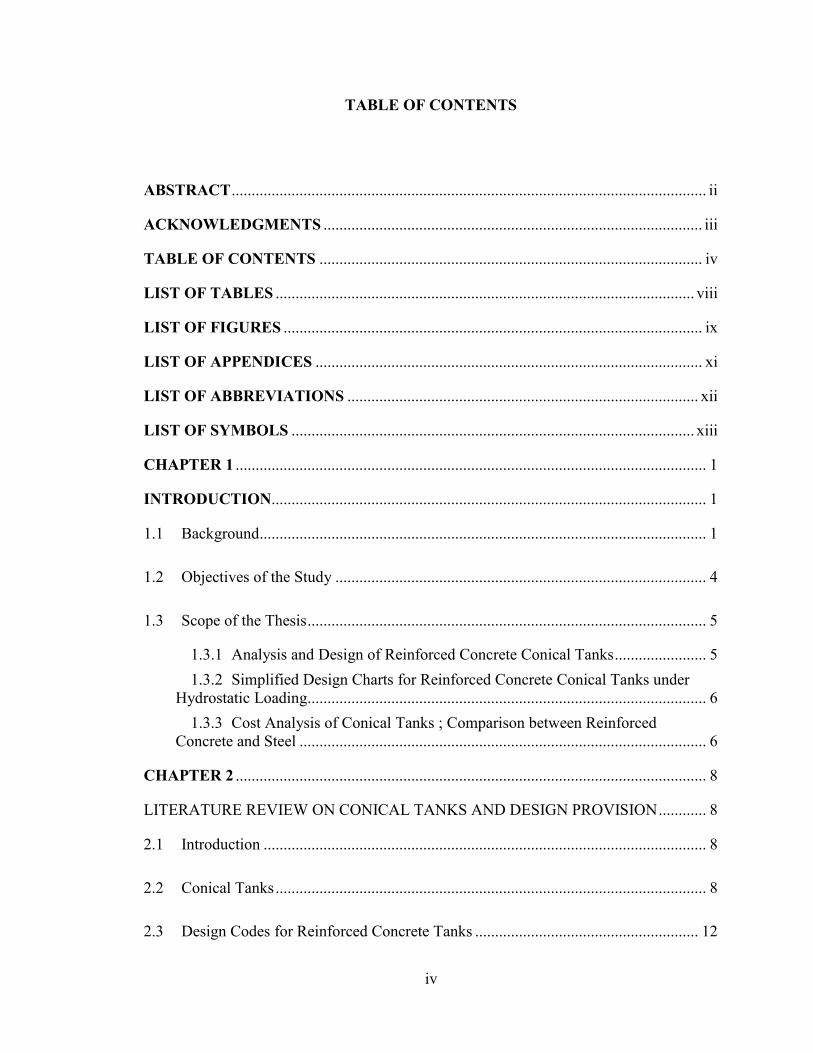
TABLE OF CONTENTS
ABSTRACT ....................................................................................................................... ii
ACKNOWLEDGMENTS ............................................................................................... iii
TABLE OF CONTENTS ................................................................................................ iv
LIST OF TABLES ......................................................................................................... viii
LIST OF FIGURES ......................................................................................................... ix
LIST OF APPENDICES ................................................................................................. xi
LIST OF ABBREVIATIONS ........................................................................................ xii
LIST OF SYMBOLS ..................................................................................................... xiii
CHAPTER 1 ...................................................................................................................... 1
INTRODUCTION............................................................................................................. 1
1.1 Background................................................................................................................ 1
1.2 Objectives of the Study ............................................................................................. 4
1.3 Scope of the Thesis .................................................................................................... 5
1.3.1 Analysis and Design of Reinforced Concrete Conical Tanks ....................... 5
1.3.2 Simplified Design Charts for Reinforced Concrete Conical Tanks under
Hydrostatic Loading.................................................................................................... 6
1.3.3 Cost Analysis of Conical Tanks ; Comparison between Reinforced
Concrete and Steel ...................................................................................................... 6
CHAPTER 2 ...................................................................................................................... 8
LITERATURE REVIEW ON CONICAL TANKS AND DESIGN PROVISION ............ 8
2.1 Introduction ............................................................................................................... 8
2.2 Conical Tanks ............................................................................................................ 8
2.3 Design Codes for Reinforced Concrete Tanks ........................................................ 12
v
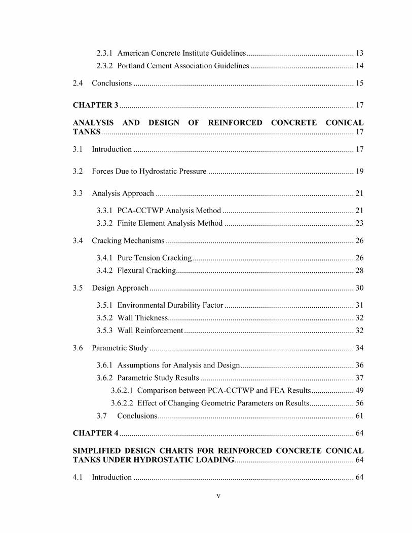
2.3.1 American Concrete Institute Guidelines ..................................................... 13
2.3.2 Portland Cement Association Guidelines ................................................... 14
2.4 Conclusions ............................................................................................................. 15
CHAPTER 3 .................................................................................................................... 17
ANALYSIS AND DESIGN OF REINFORCED CONCRETE CONICAL
TANKS ............................................................................................................................. 17
3.1 Introduction ............................................................................................................. 17
3.2 Forces Due to Hydrostatic Pressure ........................................................................ 19
3.3 Analysis Approach .................................................................................................. 21
3.3.1 PCA-CCTWP Analysis Method ................................................................. 21
3.3.2 Finite Element Analysis Method ................................................................ 23
3.4 Cracking Mechanisms ............................................................................................. 26
3.4.1 Pure Tension Cracking ................................................................................ 26
3.4.2 Flexural Cracking........................................................................................ 28
3.5 Design Approach ..................................................................................................... 30
3.5.1 Environmental Durability Factor ................................................................ 31
3.5.2 Wall Thickness............................................................................................ 32
3.5.3 Wall Reinforcement .................................................................................... 32
3.6 Parametric Study ..................................................................................................... 34
3.6.1 Assumptions for Analysis and Design ........................................................ 36
3.6.2 Parametric Study Results ............................................................................ 37
3.6.2.1 Comparison between PCA-CCTWP and FEA Results ..................... 49
3.6.2.2 Effect of Changing Geometric Parameters on Results ...................... 56
3.7 Conclusions ................................................................................................. 61
CHAPTER 4 .................................................................................................................... 64
SIMPLIFIED DESIGN CHARTS FOR REINFORCED CONCRETE CONICAL
TANKS UNDER HYDROSTATIC LOADING ........................................................... 64
4.1 Introduction ............................................................................................................. 64
vi
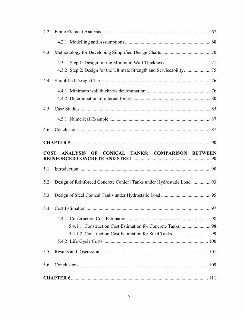
4.2 Finite Element Analysis .......................................................................................... 67
4.2.1 Modelling and Assumptions ....................................................................... 68
4.3 Methodology for Developing Simplified Design Charts ......................................... 70
4.3.1 Step 1: Design for the Minimum Wall Thickness ...................................... 71
4.3.2 Step 2: Design for the Ultimate Strength and Serviceability ...................... 75
4.4 Simplified Design Charts ........................................................................................ 76
4.4.1 Minimum wall thickness determination ...................................................... 76
4.4.2 Determination of internal forces ................................................................. 80
4.5 Case Studies............................................................................................................. 85
4.5.1 Numerical Example .................................................................................... 87
4.6 Conclusions ............................................................................................................. 87
CHAPTER 5 .................................................................................................................... 90
COST ANALYSIS OF CONICAL TANKS; COMPARISON BETWEEN
REINFORCED CONCRETE AND STEEL ................................................................ 90
5.1 Introduction ............................................................................................................. 90
5.2 Design of Reinforced Concrete Conical Tanks under Hydrostatic Load ................ 93
5.3 Design of Steel Conical Tanks under Hydrostatic Load ......................................... 95
5.4 Cost Estimation ....................................................................................................... 97
5.4.1 Construction Cost Estimation ..................................................................... 98
5.4.1.1 Construction Cost Estimation for Concrete Tanks ......................... 98
5.4.1.2 Construction Cost Estimation for Steel Tanks .............................. 99
5.4.2 Life-Cycle Costs ....................................................................................... 100
5.5 Results and Discussion .......................................................................................... 101
5.6 Conclusions ........................................................................................................... 109
CHAPTER 6 .................................................................................................................. 111
vii
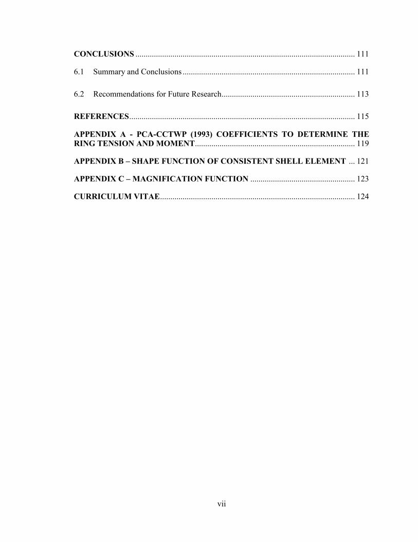
CONCLUSIONS ........................................................................................................... 111
6.1 Summary and Conclusions .................................................................................... 111
6.2 Recommendations for Future Research................................................................. 113
REFERENCES .............................................................................................................. 115
APPENDIX A - PCA-CCTWP (1993) COEFFICIENTS TO DETERMINE THE
RING TENSION AND MOMENT.............................................................................. 119
APPENDIX B – SHAPE FUNCTION OF CONSISTENT SHELL ELEMENT ... 121
APPENDIX C – MAGNIFICATION FUNCTION ................................................... 123
CURRICULUM VITAE ............................................................................................... 124
viii
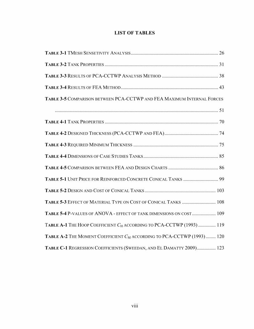
LIST OF TABLES
TABLE 3-1 TMESH SENSETIVITY ANALYSIS ...................................................................... 26
TABLE 3-2 TANK PROPERTIES ........................................................................................... 31
TABLE 3-3 RESULTS OF PCA-CCTWP ANALYSIS METHOD ............................................. 38
TABLE 3-4 RESULTS OF FEA METHOD .............................................................................. 43
TABLE 3-5 COMPARISON BETWEEN PCA-CCTWP AND FEA MAXIMUM INTERNAL FORCES
................................................................................................................................... 51
TABLE 4-1 TANK PROPERTIES ........................................................................................... 70
TABLE 4-2 DESIGNED THICKNESS (PCA-CCTWP AND FEA) ........................................... 74
TABLE 4-3 REQUIRED MINIMUM THICKNESS .................................................................... 75
TABLE 4-4 DIMENSIONS OF CASE STUDIES TANKS ............................................................ 85
TABLE 4-5 COMPARISON BETWEEN FEA AND DESIGN CHARTS ........................................ 86
TABLE 5-1 UNIT PRICE FOR REINFORCED CONCRETE CONICAL TANKS ............................ 99
TABLE 5-2 DESIGN AND COST OF CONICAL TANKS ......................................................... 103
TABLE 5-3 EFFECT OF MATERIAL TYPE ON COST OF CONICAL TANKS ........................... 108
TABLE 5-4 P-VALUES OF ANOVA - EFFECT OF TANK DIMENSIONS ON COST ................... 109
TABLE A-1 THE HOOP COEFFICIENT CH ACCORDING TO PCA-CCTWP (1993) .............. 119
TABLE A-2 THE MOMENT COEFFICIENT CM ACCORDING TO PCA-CCTWP (1993) ........ 120
TABLE C-1 REGRESSION COEFFICIENTS (SWEEDAN, AND EL DAMATTY 2009) ............... 123
ix
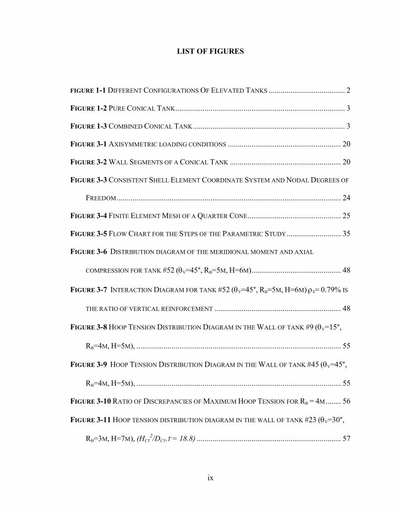
LIST OF FIGURES
FIGURE 1-1 DIFFERENT CONFIGURATIONS OF ELEVATED TANKS ....................................... 2
FIGURE 1-2 PURE CONICAL TANK ....................................................................................... 3
FIGURE 1-3 COMBINED CONICAL TANK .............................................................................. 3
FIGURE 3-1 AXISYMMETRIC LOADING CONDITIONS .......................................................... 20
FIGURE 3-2 WALL SEGMENTS OF A CONICAL TANK ......................................................... 20
FIGURE 3-3 CONSISTENT SHELL ELEMENT COORDINATE SYSTEM AND NODAL DEGREES OF
FREEDOM ................................................................................................................... 24
FIGURE 3-4 FINITE ELEMENT MESH OF A QUARTER CONE ................................................ 25
FIGURE 3-5 FLOW CHART FOR THE STEPS OF THE PARAMETRIC STUDY ............................ 35
FIGURE 3- 6 DISTRIBUTION DIAGRAM OF THE MERIDIONAL MOMENT AND AXIAL
COMPRESSION FOR TANK #52 (V=45°, RB=5M, H=6M) .............................................. 48
FIGURE 3- 7 INTERACTION DIAGRAM FOR TANK #52 (V=45°, RB=5M, H=6M) S= 0.79% IS
THE RATIO OF VERTICAL REINFORCEMENT ................................................................. 48
FIGURE 3- 8 HOOP TENSION DISTRIBUTION DIAGRAM IN THE WALL OF TANK #9 (V=15°,
RB=4M, H=5M), ......................................................................................................... 55
FIGURE 3- 9 HOOP TENSION DISTRIBUTION DIAGRAM IN THE WALL OF TANK #45 (V=45°,
RB=4M, H=5M), ......................................................................................................... 55
FIGURE 3- 11 RATIO OF DISCREPANCIES OF MAXIMUM HOOP TENSION FOR RB = 4M ........ 56
FIGURE 3-11 HOOP TENSION DISTRIBUTION DIAGRAM IN THE WALL OF TANK #23 (V=30°,
RB=3M, H=7M), (HCY2/DCY.T = 18.8) .......................................................................... 57
x
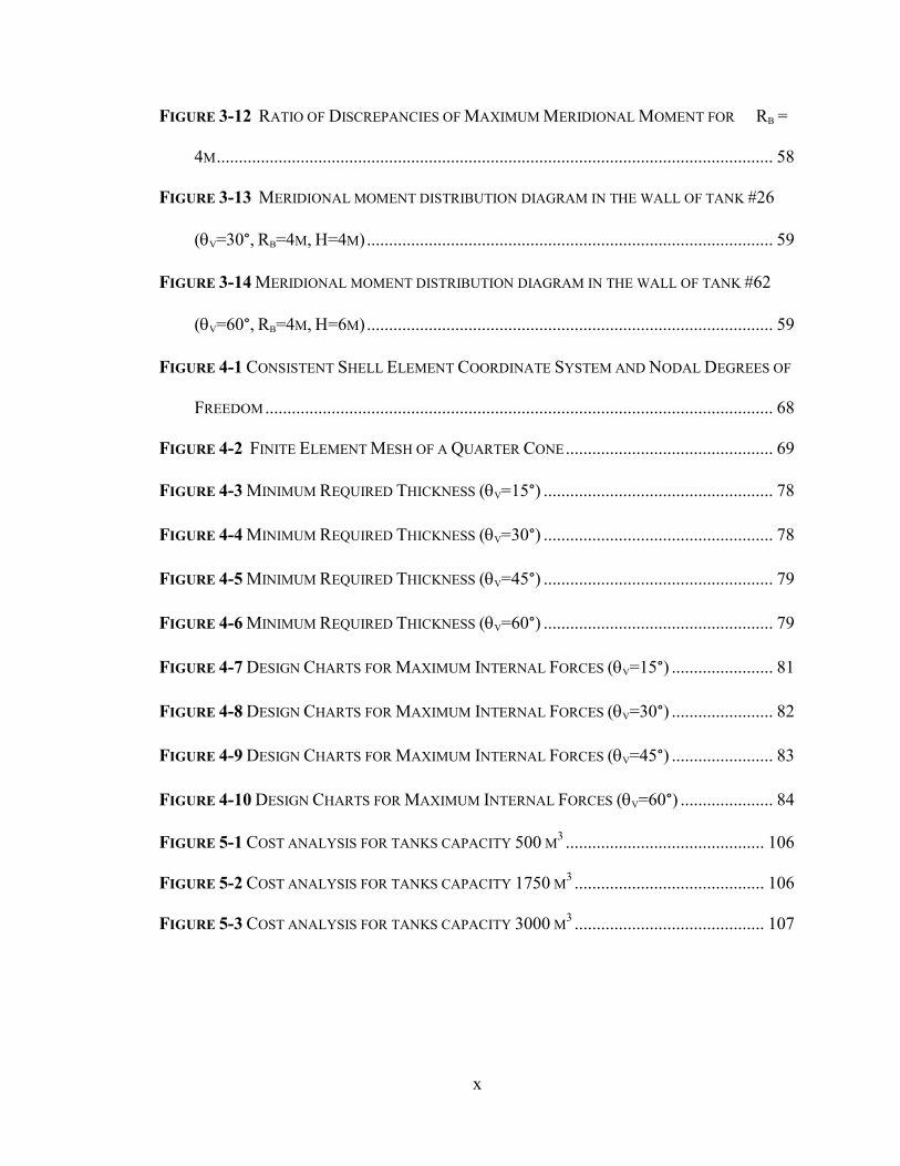
FIGURE 3- 11 RATIO OF DISCREPANCIES OF MAXIMUM MERIDIONAL MOMENT FOR RB =
4M .............................................................................................................................. 58
FIGURE 3- 13 MERIDIONAL MOMENT DISTRIBUTION DIAGRAM IN THE WALL OF TANK #26
(V=30°, RB=4M, H=4M) ............................................................................................ 59
FIGURE 3-11 MERIDIONAL MOMENT DISTRIBUTION DIAGRAM IN THE WALL OF TANK #62
(V=60°, RB=4M, H=6M) ............................................................................................ 59
FIGURE 4-1 CONSISTENT SHELL ELEMENT COORDINATE SYSTEM AND NODAL DEGREES OF
FREEDOM ................................................................................................................... 68
FIGURE 4- 1 FINITE ELEMENT MESH OF A QUARTER CONE ............................................... 69
FIGURE 4-3 MINIMUM REQUIRED THICKNESS (V=15°) .................................................... 78
FIGURE 4-1 MINIMUM REQUIRED THICKNESS (V=30°) .................................................... 78
FIGURE 4-5 MINIMUM REQUIRED THICKNESS (V=45°) .................................................... 79
FIGURE 4-6 MINIMUM REQUIRED THICKNESS (V=60°) .................................................... 79
FIGURE 4-7 DESIGN CHARTS FOR MAXIMUM INTERNAL FORCES (V=15°) ....................... 81
FIGURE 4-8 DESIGN CHARTS FOR MAXIMUM INTERNAL FORCES (V=30°) ....................... 82
FIGURE 4-9 DESIGN CHARTS FOR MAXIMUM INTERNAL FORCES (V=45°) ....................... 83
FIGURE 4-11 DESIGN CHARTS FOR MAXIMUM INTERNAL FORCES (V=60°) ..................... 84
FIGURE 5-1 COST ANALYSIS FOR TANKS CAPACITY 500 M3 ............................................. 106
FIGURE 5-1 COST ANALYSIS FOR TANKS CAPACITY 1750 M3 ........................................... 106
FIGURE 5- 3 COST ANALYSIS FOR TANKS CAPACITY 3000 M3 ........................................... 107
xi
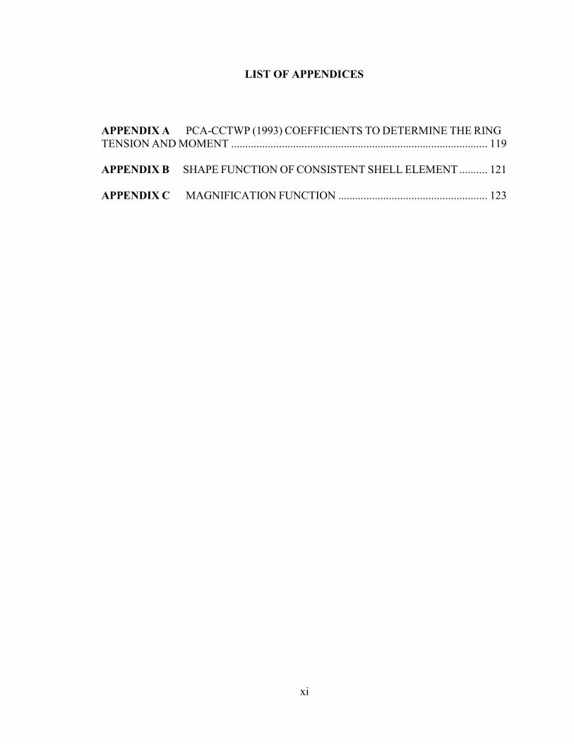
LIST OF APPENDICES
APPENDIX A PCA-CCTWP (1993) COEFFICIENTS TO DETERMINE THE RING
TENSION AND MOMENT ........................................................................................... 119
APPENDIX B SHAPE FUNCTION OF CONSISTENT SHELL ELEMENT .......... 121
APPENDIX C MAGNIFICATION FUNCTION ..................................................... 123
xii
LIST OF ABBREVIATIONS
ACI American Concrete Institute
API American Petroleum Institute
AWWA American Water Works Association
PCA Portland Cement Association
PCA-CCTWP Portland Cement Association - Circular Concrete Tanks without
Pre-stressing
FEA Finite Element Analysis
ANOVA Analysis of Variance

xiii
LIST OF SYMBOLS
u, v, w Displacement Degrees of Freedom
Ac Area of Concrete Section
Ag Concrete Gross Area
As Area of Reinforcement Steel
b Wall Section Width
C Shrinkage Coefficient
CH Hoop Coefficient
CM Moment Coefficient
db Steel Bar Diameter
Dcy Cylindrical Tank Diameter
Ec Elastic Modulus of Concrete
Es Elastic Modulus of Steel
fc The Applied Tensile Strength
fc Concrete Compressive Strength
fcr Concrete Tensile Strength
fs Stress in Reinforcement Steel at Service Loads
fsmax Steel Maximum Allowable Stress
fy Reinforcement Steel Yield Strength
H Tank Height
Hcy Cylindrical Tank Height
M Service Meridional Moment
xiv
n Modular Ratio
Rb Base Radius of the Tank
S Steel Bar Spacing
Sd Environmental Durability Factor
T Service Hoop Tension
t Wall Thickness
tcy Cylindrical Wall Thickness
tmin Steel Wall Thickness
ts Minimum Wall Thickness
Tu Factored Hoop Tension
U Factored Loads
x, y, z Global Coordinates
x, y, z Local Cartesian Coordination
a Significance Level for Analysis of Variables
Rotational Degrees of Freedom
Magnification Function
` Strain Gradient Amplification
Ratio between Factored Load and Unfactored Load
w Liquid Unit Weight
Poisson Ratio
Ø Strength Reduction Factor
v Tank Wall Inclination Angle
xv
sh Horizontal Steel Ratio
sv Vertical Steel Ratio
hth Theoretical Tensile Hoop Stress
l Total Actual Stress
lth Theoretical Maximum Effective Membrane Stresses
mth Theoretical Meridional Compression Stress
y Steel Yield Strength
1
CHAPTER 1
INTRODUCTION
1.1 Background
During the last few decades, above ground tanks were extensively constructed around the
world. These tanks play an important role to store different liquids in functional and safe
manners. The above ground tanks are categorized into ground, standpipe and elevated
tanks. Ground tanks, which are also known as reservoirs, can take different shapes (e.g.
rectangular, cylindrical, and cylindrical with conical base). Although ground tanks have a
high storage capacity due to their large diameter, they have a low operation head
pressure. Stand pipe tanks are cylindrical shape tanks that have a height up to 46 m and a
diameter ranging between 7 m and 9 m. They are characterized by high storage capacity
and high internal hydrostatic pressure. On the other hand, elevated tanks have smaller
capacity compared to standpipes and ground tanks. However, they provide high operation
pressure with relatively low internal liquid height, up to 10 m, (Grieve et al. 1987).
Many water supply systems widely utilized elevated tanks because of their advantages
that include: functional, economical and aesthetical aspects. Elevated tanks are used in
districts with high elevation since this type of tanks provides sufficient head pressure
during peak hours or even after power outages. Also, they provide lower energy cost
since the water can be pumped during off peak times. Elevated tanks are considered as an
economical solution for upgrading existing water supplying systems to satisfy the
increasing demand of water supply. Moreover, the supporting tower (i.e., supporting
shaft) of an elevated tank can be utilized as a multipurpose structure, especially for
regions with lack of space below ground. Elevated tanks present aesthetical pleasure and
2
they are considered as visible landmarks for the surrounding areas. It should be
mentioned that elevated tanks are essentially required to remain functional even during
and after disaster events to meet the emergency requirements such as firefighting and
public water demands. The damage of a storage tank containing hazardous materials (e.g.
chemicals, and fuels) can adversely affect the environment causing significant economic
loses.
Nowadays, there is an extensive need to increase the storage capacities of elevated tanks.
Therefore, elevated tanks have been built using different construction materials (e.g.
reinforced concrete, partially pre-stressed concrete, or steel), and different shapes (e.g.
rectangular, cylindrical, and conical) in order to obtain the optimum capacity in a safe
and economical manner. Figure 1-1 shows different shapes of elevated tanks.
Figure 1-1 Different Configurations of Elevated Tanks
3
A typical elevated conical tank consists of a tower that supports the superstructure (i.e.,
storage conical vessel). This tower usually has a shape of cylindrical shaft constructed of
reinforced concrete. The geometry of the conical vessel can take two configurations,
including pure conical and combined conical cylindrical shapes. A pure conical tank is
defined as a vessel that has a pure truncated conical geometry (Figure 1-2), while a
combined conical tank refers to a conical vessel that has a superimposed top cylindrical
cap (Figure 1-3).
Elevated conical tanks are considered as one of the most popular constructions since they
provide greater liquid retaining capacity for the same base radius of a cylindrical
counterpart. These tanks require also lower height of water for the same containing
volume of the cylindrical shape. Consequently, the hydrostatic pressure acting on the
vessel base is minimized, leading to an increase in its structural efficiency. Moreover, a
large containing volume can be achieved without having the base over hanged and
cantilevered from the supporting tower as in the case of elevated cylindrical tanks.
Conical vessel
Supporting slab
Supporting tower
Figure 1-2Pure Conical Tank Figure 1-3Combined Conical Tank Figure 1-3 Combined Conical Tank Figure 1-2 Pure Conical Tank
Upper cylindrical part
4
Conical tanks are more economical than cylindrical tanks that have the same capacity.
The total cost of reinforced concrete cylindrical tanks is 18% to 40% more than that of
conical tanks having the same capacity, as stated by Barakat and Altoubat (2009).
As mentioned earlier, different materials can be used in the construction of such storage
tanks. Selecting the proper construction material depends mainly on various criteria,
including; required storage capacity, service life, structural performance, construction and
operation cost. According to Meier (2002), steel is widely used as the construction
material for tanks built in Canada and USA over the last 25 years. This is related to the
fact that such tanks provide high tension resistance and lighter own weight compared to
those constructed from reinforced concrete. The drawback of using steel as a construction
material for liquid-filled tanks is that steel vessels might suffer from corrosion, buckling
and geometric imperfections. On the other hand, reinforced concrete tanks provide high
resistance to compression stresses and they have long service life (i.e., up to 50 years)
compared to steel tanks (i.e., up to 20 years). However, the main concern about
reinforced concrete tanks is related to the low tensile strength and the large required wall
thickness which leads to a significant own weight (Cheremisinoff, 1996).
1.2 Objectives of the Study
The main objectives of the present research are as follows:
1. Investigate the applicability of the available design provisions when applied to design
reinforced concrete conical tanks
2. Develop a simple procedure in the form of design charts for analysing and designing
liquid-filled reinforced concrete conical tanks. These charts are developed based on
5
coupling code requirements with a set of data obtained from finite element analysis of
a number of tanks covering a wide practical range of geometrical parameters.
3. Utilize the simplified approach developed in step 2 to perform cost analysis for
reinforced concrete tanks and investigate the economics of these concrete tanks
versus steel counterparts.
1.3 Scope of the Thesis
This thesis has been prepared in “Monograph” format. This chapter introduces the
general background and the main objectives of this research. In the next chapter, a review
of previous researches and current available design codes as well as the motivation for
the study are presented. The following three chapters address the objectives of this
research. Chapter 6 presents relevant conclusions of the study together with suggestions
for further research.
1.3.1 Analysis and Design of Reinforced Concrete Conical Tanks
In chapter 3, several reinforced concrete conical tanks subjected to hydrostatic pressure
are analyzed and designed. Two different analysis methods are utilized to evaluate the
internal forces for each tank. The first method follows a simplified approach provided by
Portland Cement Association for concrete circular tanks combined with equivalent
cylinder method to transfer conical shape tanks to equivalent cylinders. The second
method is a linear Finite Element Analysis model built in-house and is based on a
degenerated consistent sub-parametric shell element. A parametric study is conducted for
a wide range of conical tanks with different configurations in order to compare the results
6
obtained from these two analysis methods. The results of this parametric study are
utilized to assess the adequacy of code provisions available for cylindrical tanks when
applied on conical shape vessels.
1.3.2 Simplified Design Charts for Reinforced Concrete Conical Tanks under
Hydrostatic Loading
The objective of chapter 4 is to develop simplified design charts in order to design
reinforced concrete conical tanks under the effect of hydrostatic pressure. A number of
conical tanks are analyzed using a built in-house finite element model that is based on a
degenerated consistent shell element. These tanks are initially designed to comply with
the recommendations of both American Concrete Institute for liquid retaining structures
(ACI350-06), and Portland Cement Association guidelines for the analysis and design of
circular concrete tanks (PCA-CCTWP, 1993). Finally, a comparison between the finite
element model and design charts is conducted to validate the accuracy of the developed
charts. Useful conclusions are achieved from this study.
1.3.3 Cost Analysis of Conical Tanks ; Comparison between Reinforced
Concrete and Steel
In chapter 5, the economics of reinforced concrete conical tanks are investigated by
comparing the cost of reinforced concrete and steel as construction materials used for
such tanks. The design charts, which are introduced in chapter 4, are employed to design
a number of reinforced concrete conical tanks having different capacities. The steel
conical tanks are designed by using a simplified approach that was developed in a
previous investigation. The cost analysis is implemented for each of the concrete and
7
steel tanks. This analysis includes the cost of materials, formwork, labour and life-cycle
cost. Also, a general study of the effect of tank dimensions is presented.
8
2 CHAPTER 2
LITERATURE REVIEW ON CONICAL TANKS AND DESIGN PROVISIONS
2.1 Introduction
This chapter presents a review of the available literature regarding conical tanks and code
provisions for design of reinforced concrete tanks.
2.2 Conical Tanks
Design of axisymmetric structures (e.g. conical tanks) depends on the concept of surface
of revolution that is developed by the rotation of the curved surface (i.e. conical tank
wall) about the vertical axis lying in the same plane. Based on this concept, Ghali (1979)
presented an analytical method for the evaluation of circular cylindrical tanks subjected
to hydrostatic pressure. According to Ghali (1979), it is sufficient to consider an element
strip of one meter along the circumference of the wall and parallel to the cylinder axis.
Under the effect of axisymmetric loading, the wall strip is assumed to deflect as a beam
on elastic foundation. Therefore, Ghali presents the general elastic solution for circular
tanks that is based on finite difference method. This method has been applied to conical
shape tanks but without taking into account the effect of vertical components of the
hydrostatic pressure. Hilal (1988) utilized the theory of plates and shells to design a paste
tank having a funnel shape by presenting a set of equations to determine the hoop and
meridional moments at different heights of the tank. This method is based on static
analysis and is found to lead to conservative design. In 2000, Ghali extended his work to
include a one dimensional straight finite element represented as a conical frustra and can
9
be generalized for any shape. However, this element does not account for the spurious
shear modes and locking phenomenon.
Intensive studies on liquid containing conical tanks started after a catastrophic failure of a
steel conical water tank in Belgium in 1978. One of these studies was initiated at Ghent
University by Vandepitte et al. (1982). The research was mainly conducted
experimentally. A large number of small-scale conical vessel models were constructed.
The models had different dimensions and were made of different materials. The
experiments were conducted by gradually increasing the height of water inside the
models. The water height at which each model buckled was detected. The experimental
results were employed to develop a set of equations that can be used to assess the stability
of conical tanks. Later on, Bornscheuer et al. (1983) studied the elasto-plastic behaviour
of conical vessels using a degenerated shell element. The results of their study showed
that the buckling strength of the studied tanks is significantly reduced by the presence of
axisymmetric imperfections.
In 1990, another catastrophic failure of an elevated conical tank occurred in Fredericton,
Canada. Vandepitte (1999) related this failure to the inappropriate thickness of the lower
part of the tank. The miscalculation of the thickness was attributed to the reason that the
designer used buckling formulae that are valid for aerospace applications where the
quality of the manufacturing is much higher than that in civil projects. Another
investigation that was conducted by El Damatty et al. (1997) studied the elastic stability
of a conical vessel under hydrostatic load assuming perfect shells. In their study, the
imperfection shape, which leads to the lowest limit load, was determined by conducting
elastic analyses of conical tanks with different imperfections. The study indicated that the
11
limit load for hydrostatically loaded conical vessels is reduced by the presence of an
axisymmetric imperfection shape resulting from welding of curved steel panels.
Furthermore, it was noticed that the smaller the thickness of a conical tank, the more the
structure is sensitive to geometric imperfections. Lagae et al. (2007) conducted a
numerical simulation of steel conical tanks with large axisymmetric imperfections. This
study showed that circumferential stresses are increased by axisymmetric imperfections
causing local yielding to precipitate the buckling failure. All of these previous studies
focused mainly on the behaviour of steel conical tanks which shows complexity in the
analysis and design of these storage vessels. This complexity motivates Sweedan and El
Damatty (2009) to develop a simplified procedure for the design of hydrostatically loaded
combined conical tanks. In this procedure, a magnification function was provided in
order to relate the maximum overall stresses developed in the tank walls to the theoretical
membrane stresses resulting from static equilibrium of the shell under internal hydrostatic
pressure.
Despite all these previous studies related to conical tanks, which focused on steel as a
construction material, there is a lack in the literature regarding reinforced concrete
conical tanks. The literature shows only few records for collapses of reinforced concrete
elevated conical tanks occurred mainly during past earthquakes. For example, in 1997,
the Jabalpur earthquake caused failure of elevated conical water tank having a capacity of
2270 m3. Another three reinforced concrete conical tanks collapsed during the Bhuj
earthquake in 2001 (Rai, 2002). These failures grabbed the attention of a number of
researchers to study the behaviour of such tanks. Most of these studies focused on the
11
supporting shafts and did not investigate the conical vessel itself (Rai 2003, Sezen et al.
2008, Dutta et al. 2009).
Barakat and Salah (2009) introduced an application of optimization techniques, which
were combined with the finite element method, in the analysis and design of reinforced
concrete conical and cylindrical water tanks. The finite element model was based on a 4-
node axisymmetric quadrilateral shell element. In addition, they illustrated the effect of
different parameters on the optimum design. This study concluded that shear strength and
crack width are the governing criteria that determine the optimum design based on
working stress design method while crack width is the governing requirement in the
strength-based formulation. According to Barakat and Altoubat (2009), the total cost for
cylindrical tanks is found to be more than that for conical water tanks of the same volume
by (20% to 30%) and by (18% to 40%) when working stress design method and strength
design method are used, respectively.
Based on the information presented above, it can be concluded that most of the published
literature studied the structural behaviour of steel conical tanks. However, there is scant
data available for the design and performance of reinforced concrete tanks. Moreover,
the effect of different loads, e.g. dead, hydrostatic, and earthquake loads, on the
behaviour of the supporting shaft of a reinforced concrete tank was investigated using
finite element methods, while there is no clear understanding of the behaviour of the
conical vessel of these tanks.
12
2.3 Design Codes for Reinforced Concrete Tanks
Since 1940, reinforced concrete liquid storage tanks and their properties have long been
studied. Earlier studies done by Slater (1940), Gray (1948), Timoshenko and Woinowski-
Krieger (1959), and Wilby (1977) provided the basis for the design of such tanks. Those
researchers proposed that the analysis of reinforced concrete tanks can be based on a
linear approach.
The theory of plates and shells, which was introduced by Timoshenko and Woinowski-
Krieger (1959), indicated that all problems of symmetrical deformation of cylindrical
shells under uniformly distributed load can be expressed as a function of radial
displacement at an arbitrary height. Latterly, Ghali (1979) presented an analytical
method for the evaluation of circular cylindrical tanks subjected to hydrostatic pressure.
According to Ghali (1979), it is sufficient to consider an element strip of one meter along
the circumference of the wall and parallel to the cylinder axis. He proposed that such a
wall strip behaves as a beam on elastic foundation. Due to the inclination of the tank`s
wall, the behaviour of reinforced concrete conical tanks under hydrostatic loading differs
from that of circular cylindrical tanks.
In addition to structural requirements, reinforced concrete tanks have to satisfy the
durability needs, leading to functional success during the service life. Grieve et al. (1987)
presented a report to investigate and inspect several above ground reinforced concrete
tanks in Ontario. According to this report, 53 above ground tanks, which were
constructed during the period of 1956 to 1980, suffered from deteriorations and cracks,
and functionally failed although they were structurally accepted. This report reflects the
importance of durability and service life of reinforced concrete tanks. During that time
13
and later on, many committees have been established to analyze and design liquid
retaining structures, including: Portland Cement Association Circular Concrete Tanks
without Pre-stressing (PCA-CCTWP), American Concrete Institute Design:
Considerations for Environmental Engineering Concrete Structures (ACI350-06), British
Standard Institute: Code of Practice for the Design of Concrete Structures for Retaining
Aqueous Liquids (BS 8007), and Eurocode: Design of Concrete Structures – Part 3
Liquid Retaining and Containment Structures (EN 1992-3). The PCA- CCTWP and
ACI350-06 are globally used while BS 8007 and Eurocode are the predominated choice
in Europe.
Recently, many researchers investigated the behaviour and design of reinforced concrete
tanks,especiallyforrectangularandcylindricalshapetanks.Tothebestoftheauthor’s
knowledge, there are no particular provisions or standards that are available for concrete
conical tanks. However, it is important to review current design codes that provide
recommendations and standards for cylindrical and rectangular reinforced concrete tanks.
This can help in establishing future procedures for reinforced concrete conical tanks. The
majority of designers use strength design method, yet some still use working stress design
approach. In the working stress method, stresses are kept at fairly low levels to minimize
cracking, which leads to prevention of leakage. On the other hand, strength design
method deals with cracked section analysis, which may not sufficiently address the
leakage problem in liquid-filled structures.
2.3.1 American Concrete Institute Guidelines
In 1964, the American Concrete Institute (ACI) established a committee (ACI350-64) to
provide guidelines for the design of liquid retaining reinforced concrete structures. The
14
most recent version of this guideline is the ACI 350-06. The basic design philosophy of
this code is to reduce the stresses on the reinforcement under the effect of applied
working stress. This code (ACI 350-06) provides an expression to calculate the maximum
stress in the steel, which should not be exceeded, in order to keep the crack width less
than the allowable width.
ACI 350-06 limits the flexural cracks to 0.27 mm and 0.23 mm for normal and sever
environmental exposures, respectively. It should be mentioned that ACI 350-06 refers to
another code ACI 224R-01 to control the cracking in environmental engineering concrete
structures such as elevated conical tanks. Conservatively, ACI 224R-01 specifies 0.1 mm
as the maximum allowable crack width in order to protect the steel reinforcement from
corrosion. For resisting the shrinkage and temperature effects, ACI 350-06 provides
minimum reinforcement ratio to be ranging between 0.3% and 0.6%. Moreover, ACI
350-06 limits the minimum thickness to 300 mm for walls equal to or higher than 3 m
height. ACI 350-06 refers to the Portland Cement Association code of practice (PCA-
CCTWP, 1993) for the analysis and design of cylindrical concrete tanks while it does not
refer to any codes for the design of conical shaped tanks.
2.3.2 Portland Cement Association Guidelines
The Portland Cement Association (PCA) provided guidelines for analysis and design of
rectangular and cylindrical reinforced concrete tanks (PCA 1942, 1963, 1981, and 1993).
However, PCA does not specify any recommendations for conical shape tanks. The most
widely used code for design of cylindrical concrete tanks is PCA-CCTWP (1993). The
advantage of this code over others is that it provides guidelines for the carrying capacity
15
of the stresses in concrete resulting from ring tension. It includes coefficients for
evaluating the ring tensions, moments and shears in cylindrical tank walls.
Several studies were published to investigate the discrepancy between PCA-CCTWP and
other design guidance. Godbout et al. (2003) evaluated analytically the internal forces in
a cylindrical tank wall and compared them with to those obtained from PCA-CCTWP-93.
It was concluded that the estimated internal forces developed in the cylindrical walls (i.e.,
circumferential tensions and vertical bending moments) agreed well with the code results.
Bruder (2011) evaluated the internal forces of the walls of cylindrical concrete tanks with
a conical base. He used two different analysis methods; PCA-CCTWP and finite element
analysis (FEA). It was reported that there was a disagreement between these two
methods. Also, Bruder (2011) concluded that FEA should be employed if the tank
parameters (e.g. shape, load cases, and boundary conditions) are not covered by PCA-
CCTWP. However, this study did not present any information about the analysis of the
conical part of the tank.
2.4 Conclusions
Elevated reinforced concrete conical tanks are widely used for storage of different liquids
since they provide greater capacity with lower liquid height. Although most codes
provide guidelines for analysis and design of reinforced concrete rectangular and
cylindrical tanks, no guidance is provided in such codes for conical shape tanks. The
literature shows that most of the previous studies focused on the structural behaviour of
steel conical tanks. However, there is scant data available for the design and behaviour of
reinforced concrete tanks. It is important to review the current design codes that provide
16
recommendations and standards for reinforced concrete tanks. These codes which mainly
provide guidelines for cylindrical tanks might be employed to design reinforced concrete
conical tanks.
FEA is a predominate choice for analysis of conical tanks due to the complexity of the
analysis of these conical shaped tanks. The parameters that lead to such complexity
include the angle of inclination of the tank wall with the vertical axis, total height of the
tank and the base radius. Therefore, there is an extensive need to establish a simplified
method for design and analysis of such tanks that can be used separately or in
conjunction with FEA models, leading to an economical and safe design.
17
3 CHAPTER 3
ANALYSIS AND DESIGN OF REINFORCED CONCRETE CONICAL TANKS
3.1 Introduction
Elevated tanks are playing very important role in municipal systems. Their roles are to
contain different liquids at sufficient head pressure, and to satisfy the emergency
requirements after any disaster that might happen. Elevated tanks are made from steel,
reinforced concrete, or partially pre-stressed concrete. Moreover, they can take different
shapes such as rectangular, cylindrical or conical. Reinforced concrete is used as a
construction material for elevated conical tanks because of its advantages such as
strength, durability, low maintenance cost and high buckling resistance compared to steel
counterparts.
The structural design of reinforced concrete conical tanks includes selection of adequate
wall thickness, circumferential and longitudinal reinforcement steel, and related detailing.
Serviceability is the most important design requirement for such a type of structures and
mainly governs the design. Moreover, the design of conical tanks has to satisfy the
general requirements of environmental engineering concrete structures specified by
ACI350 (2006). Although most design codes provide guidelines for rectangular and
cylindrical tanks, no guidance is provided in such codes for conical tanks. The analysis
and design of conical tanks under the effect of hydrostatic pressure incorporates the
presence of many parameters, including the angle of inclination of the tank wall with the
vertical axis, total height of the tank and the base radius. The evaluation of the internal
18
forces in a conical tank wall is not an easy task because of the complicated state of
stresses that includes bending stresses as well as membrane stresses. In addition, current
available codes do not provide any guidelines to evaluate these internal forces.
Consequently, two different analysis methods are presented in this study. The first
method follows a simplified approach given in the Portland Cement Association for
Concrete Circular Tanks without Pre-stressing (PCA-CCTWP, 1993). Although, this
approach is specific for cylindrical tanks, an attempt is made in this study to extend it to
conical tanks. This is done by combining this approach with a procedure to transform the
geometry of a conical tank to an equivalent cylinder based on the information provided in
the American Water Works Association AWWA-D100 (2005). The second method is
based on a Finite Element Analysis (FEA) model built in-house using a degenerated
consistent sub-parametric shell element developed by Koziey and Mirza (1997). In this
study, both methods are used to investigate the behaviour of reinforced concrete conical
tanks.
Elevated conical tanks can be subjected to different types of loading such as hydrostatic
pressure, earthquake and wind loads. The current study only focuses on the effect of
axisymmetric hydrostatic pressure. The study proceeds by first analyzing a number of
conical tanks having different practical geometric parameters using the PCA-CCTWP
procedure. This involves trials that are carried out in order to obtain the required
thickness and the amount of reinforcement that comply with the recommendations of
ACI350-06. Second, the designed thickness, which is obtained from PCA-CCTWP, is
used in the FEA to model the chosen conical tanks. Third, a comparison is conducted
between the internal forces obtained from PCA-CCTWP procedure and those predicted
19
by the FEA. Finally, the wall section, which was first designed by PCA-CCTWP
approach, is checked for ultimate strength requirements of ACI350-06 under the internal
forces determined by FEA.
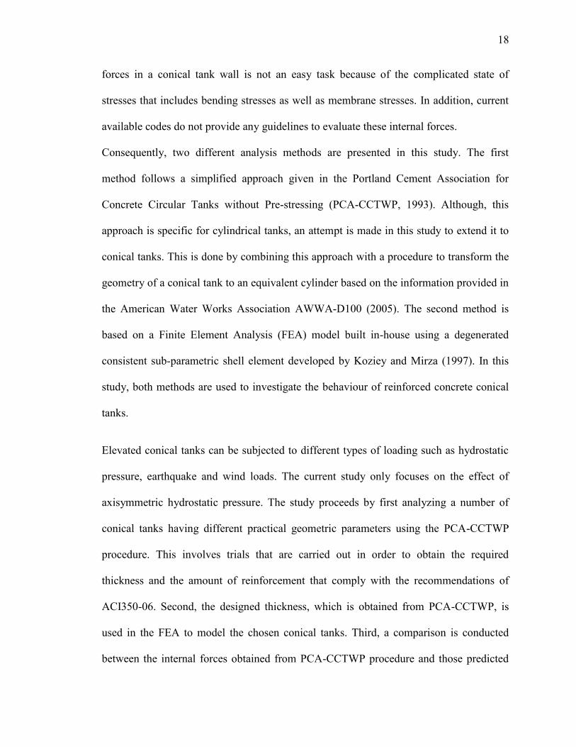
3.2 Forces Due to Hydrostatic Pressure
The weight of the contained liquid exerts an internal hydrostatic pressure on the tank
walls. The hydrostatic pressure varies linearly along the wall height while it is constant
along the circumferential direction of the wall as shown in Figure 3-1. In cylindrical
tanks, the horizontal hydrostatic pressure results in outward displacement that is
prevented due to the symmetry of the tank vessel, leading to both hoop tension force and
meridional moment. The hoop tension acts on the vertical segment of the circular wall
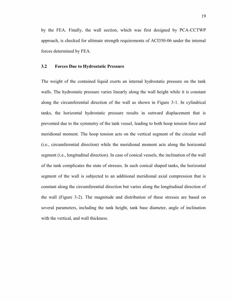
(i.e., circumferential direction) while the meridional moment acts along the horizontal
segment (i.e., longitudinal direction). In case of conical vessels, the inclination of the wall
of the tank complicates the state of stresses. In such conical shaped tanks, the horizontal
segment of the wall is subjected to an additional meridional axial compression that is
constant along the circumferential direction but varies along the longitudinal direction of
the wall (Figure 3-2). The magnitude and distribution of these stresses are based on
several parameters, including the tank height, tank base diameter, angle of inclination
with the vertical, and wall thickness.
21
N
t
M
T
t
1 m
1 m
X
Y
Z
Circumferential
direction
Longitudinal
direction
Rb
t V
Z
P H
X
Y
Z
P
Figure 3-1 Axisymmetric Loading Conditions
Figure 3-2 Wall Segments of a Conical Tank
Vertical segment in the circumferential direction and
Horizontal segment in the longitudinal direction
21
3.3 Analysis Approach
This study employs the two different methods described earlier for the analysis and
design of conical tanks. The first method is based on using PCA-CCTWP provisions for
cylindrical concrete tanks combined with a procedure to transform conical tanks into
equivalent cylinders. The second method is based on a FEA model, which is
recommended for tank shapes that fall outside the parameters outlined by PCA-CCTWP
(Bruder 2011).
3.3.1 PCA-CCTWP Analysis Method
Portland Cement Association provides a commonly used publication known as circular
concrete tanks without pre-stressing (PCA-CCTWP). In this publication, tabled
coefficients, including CH, and CM, are presented in order to simplify the evaluation of
different forces in the walls of a liquid-filled circular tank under different support
conditions. The provided coefficients are based on theory of plates and shells (Kamara
2010). PCA-CCTWP does not account for the meridional compression resulting from the
self-weight of the circular walls. The tabled hoop coefficient CH is function of the ratio
, where is the total height of the cylindrical tank, is the diameter of the
circular tank, and is the wall thickness. Based on the equations provided by PCA-
CCTWP, the internal forces acting at different heights of the circular wall can be
calculated by applying Equations 3.1 and 3.2 for evaluating the hoop tension (T) and
meridional moment (M), respectively.
(3.1)
22
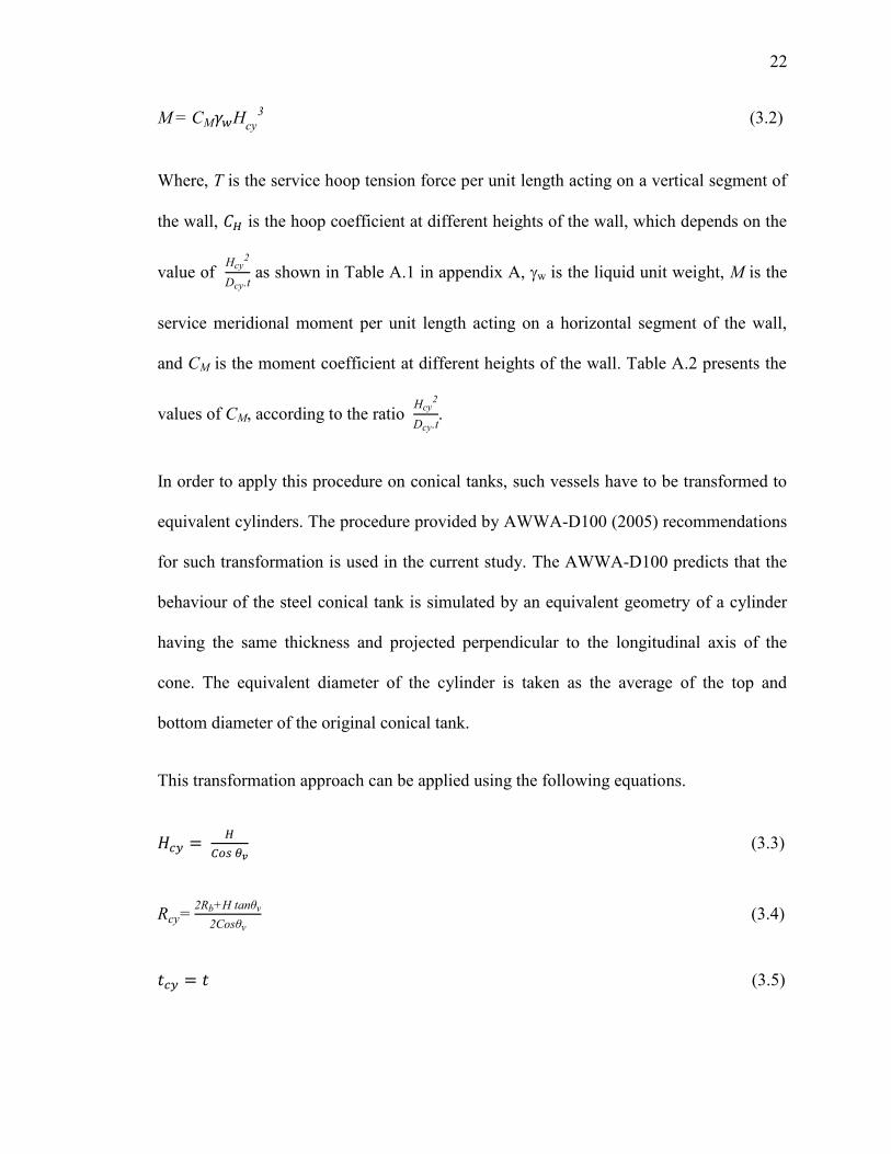
(3.2)
Where, T is the service hoop tension force per unit length acting on a vertical segment of
the wall, is the hoop coefficient at different heights of the wall, which depends on the
value of
as shown in Table A.1 in appendix A, w is the liquid unit weight, M is the
service meridional moment per unit length acting on a horizontal segment of the wall,
and CM is the moment coefficient at different heights of the wall. Table A.2 presents the
values of CM, according to the ratio
.
In order to apply this procedure on conical tanks, such vessels have to be transformed to
equivalent cylinders. The procedure provided by AWWA-D100 (2005) recommendations
for such transformation is used in the current study. The AWWA-D100 predicts that the
behaviour of the steel conical tank is simulated by an equivalent geometry of a cylinder
having the same thickness and projected perpendicular to the longitudinal axis of the
cone. The equivalent diameter of the cylinder is taken as the average of the top and
bottom diameter of the original conical tank.
This transformation approach can be applied using the following equations.
(3.3)
(3.4)
(3.5)
23
Where, and are the height and the radius of the equivalent cylinder, respectively.
H is the total height of the conical tank, is the angle of inclination of the meridian with
the vertical, Rb is the base radius of the conical tank, tcy is the wall thickness of the
equivalent cylindrical tank, and t is the wall thickness of the conical tank.
3.3.2 Finite Element Analysis Method
In this study, a finite element model based on a degenerated consistent sub-parametric
shell element is used. The consistent shell element is an excellent tool to analyze plates
and shell structures. It was successfully used in several previous studies and was
validated versus many experimental and numerical results (e.g., Koziey and Mirza 1997;
El Damatty et al. 1997, 1998; Sweedan and El Damatty 2002). This element was
developed by Koziey and Mirza (1997) and extended by El Damatty et al. (1997) to
include the geometric nonlinear effects. The consistent shell element has two main
advantages. First, it eliminates the spurious shear modes and locking phenomenon
observed when many isoparametric elements are used to model shell structures. Second,
its formulation includes special rotational degree of freedom that lead to cubic variation
of the displacement through the thickness. As such, quadratic transverse shear strain and
shear stress can be predicted by this element. This feature is very useful in analyzing
thick plates and shell structures such as reinforced concrete conical tanks.
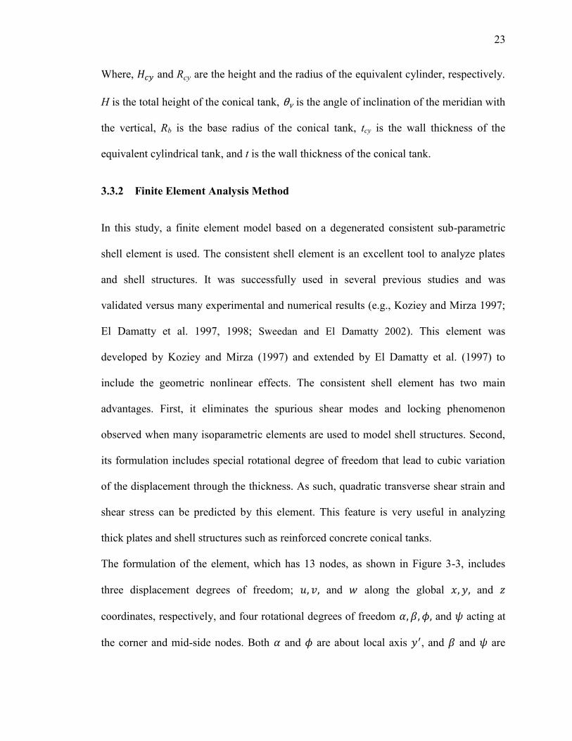
The formulation of the element, which has 13 nodes, as shown in Figure 3-3, includes
three displacement degrees of freedom; and along the global and
coordinates, respectively, and four rotational degrees of freedom and acting at
the corner and mid-side nodes. Both and are about local axis , and and are
24
about local axis x′, where the local axes ′ and x′ are located in a plane tangent to the
surface. Rotations and are constant through the depth of the element, while rotations
and vary quadratically. Thus, and provide a linear variation of displacements
and along the thickness representing bending deformations, while and lead to
a cubic variation of displacements and , simulating transverse shear deformations.
The shape functions of the consistent shell element are given in Appendix B.
Both the load acting on the tank walls resulting from hydrostatic pressure and the tank
geometry are symmetric about two perpendicular axes located in the cross sectional plan
of the tanks. Accordingly, one quarter of the tank is modeled in the analysis. The vertical
projection of a typical finite element mesh for one quarter of a conical vessel is shown in
Figure 2-3 Consistent Shell Element Coordinate
System and Nodal Degrees of Freedom
4
6
2
5 7
8
9
1
10 11 3
Z, w
12
13
Y, v
X, u
y′
x′
z′
Active degrees of freedom
ui vi wi i i i i
i i i i
ui vi wi
Figure 3-3 Consistent Shell Element Coordinate
System and Nodal Degrees of Freedom
25
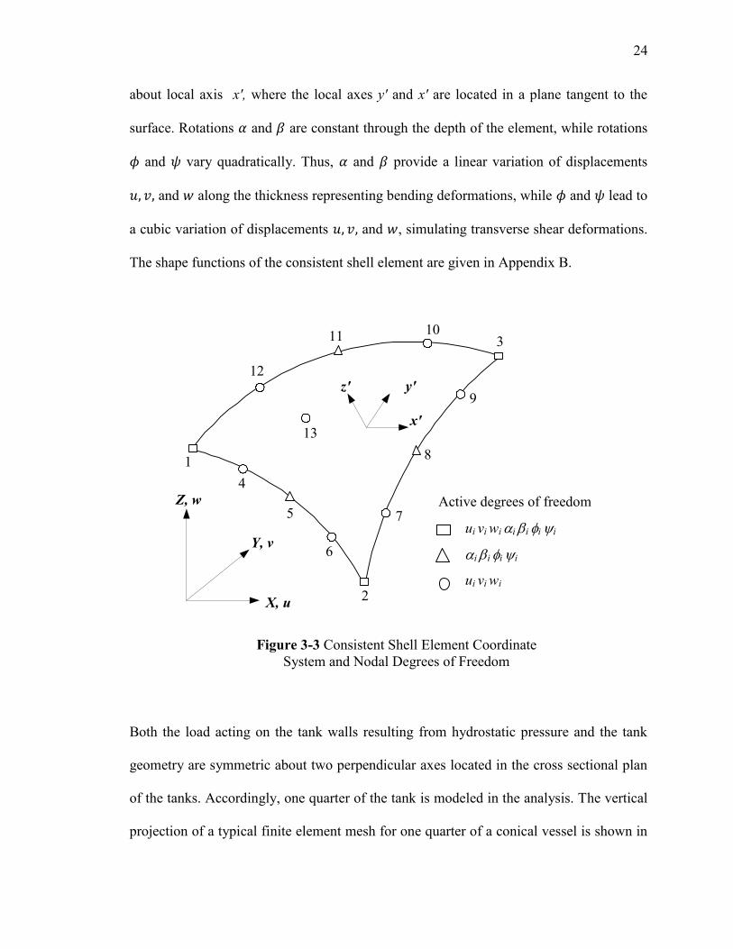
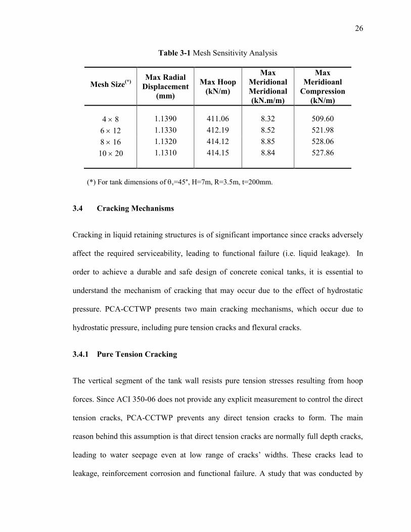
Figure 3-4. As shown in this figure, the mesh is developed using 256 triangular elements,
with 8 and 16 rectangular divisions along the circumferential and longitudinal directions,
respectively. A finer mesh is applied at the bottom region of the vessel where stress
concentration is anticipated near the tank base. The mentioned mesh size is selected
based on a sensitivity analysis that is conducted for one of the tanks (v=45°, H=7m,
R=3.5m, t=200mm) using different mesh sizes under the same hydrostatic pressure as
presented in Table 3-1. This optimum mesh size which yields to accurate radial
displacements has been used for all other studied tanks. At the base of the vessel, the
boundary conditions are assumed to be simply supported. The tank wall is assumed to be
hinged at the base since the hoop tension predicted following this assumption is greater
than that in case of fixed bottom edge of the wall (CPA-CCTWP, 1993). A free edge
boundary condition is assumed at the top of the conical vessel. This assumption is valid
since the hydrostatic pressure at the top is negligible and the radial displacement at the
top is so small (El Damatty et al. 1997).
Figure 3-4 Finite Element Mesh of a Quarter Cone
26
Table 3-1 Mesh Sensitivity Analysis
(*) For tank dimensions of v=45°, H=7m, R=3.5m, t=200mm.
3.4 Cracking Mechanisms
Cracking in liquid retaining structures is of significant importance since cracks adversely
affect the required serviceability, leading to functional failure (i.e. liquid leakage). In
order to achieve a durable and safe design of concrete conical tanks, it is essential to
understand the mechanism of cracking that may occur due to the effect of hydrostatic
pressure. PCA-CCTWP presents two main cracking mechanisms, which occur due to
hydrostatic pressure, including pure tension cracks and flexural cracks.
3.4.1 Pure Tension Cracking
The vertical segment of the tank wall resists pure tension stresses resulting from hoop
forces. Since ACI 350-06 does not provide any explicit measurement to control the direct
tension cracks, PCA-CCTWP prevents any direct tension cracks to form. The main
reason behind this assumption is that direct tension cracks are normally full depth cracks,
leading to water seepage even at low range of cracks’ widths. These cracks lead to
leakage, reinforcement corrosion and functional failure. A study that was conducted by
Mesh Size(*)
Max Radial
Displacement
(mm)
Max Hoop
(kN/m)
Max
Meridional
Meridional
(kN.m/m)
Max
Meridioanl
Compression
(kN/m)
4 8 1.1390 411.06 8.32 509.60
6 12 1.1330 412.19 8.52 521.98
8 16 1.1320 414.12 8.85 528.06
10 20 1.1310 414.15 8.84 527.86
27
Ziari and Kianoush (2009) showed that leakage can begin at a very low crack width of
0.04 mm. Also, a reduction in the rate of leakage is observed over time due to self-
healing of cracks. The self-healing can be defined as the ability of concrete to heal its
cracks which have a width less than 0.2 mm. When the water flows in the micro-cracks, it
reacts with non-hydrated cement molecules to produce further limestone, which fills
these cracks. The ACI350-06 code does not account for self-healing of cracks when
exposed to water flow in case of water tanks although it was found that 0.2 mm width
cracks can be sealed after seven weeks of continuous exposure to water (Ziari and
Kianoush 2009).
Based on the requirements of PCA-CCTWP and ACI350-06, the applied tension stresses
should not exceed the allowable tensile stress of concrete, which is considered as 10% of
the compressive strength. The cracks are only governed by the tensile strength of
concrete while the reinforcements control the crack width and do not prevent occurring of
cracks. The applied tension stress includes the combined hoop tension and shrinkage
effect acting on the area of the wall section transformed to concrete.
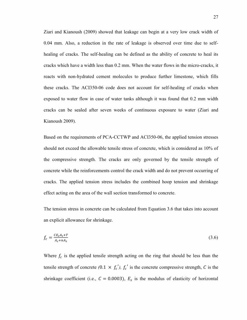
The tension stress in concrete can be calculated from Equation 3.6 that takes into account
an explicit allowance for shrinkage.
(3.6)
Where is the applied tensile strength acting on the ring that should be less than the
tensile strength of concrete ( ),
is the concrete compressive strength, is the
shrinkage coefficient (i.e., , is the modulus of elasticity of horizontal
28
reinforcement steel, is the area of horizontal reinforcement per 1000 mm height
section, is the non-factored ring hoop force per 1000 mm length resulting from the
hydrostatic pressure, is the area of concrete for 1000 mm height section (i.e.,
, t is the wall thickness, is the modular ratio (i.e.,
), and is the
concrete modulus of elasticity.
3.4.2 Flexural Cracking
Although PCA-CCTWP and ACI350-06 don’t allow direct tension cracks to occur,
flexural cracking is allowed to be formed. This is justified by the fact that flexural cracks
are less severe than the direct tension cracks. ACI350-06 limits the flexural cracks to 0.27
mm and 0.23 mm for normal and severe environmental exposures, respectively. The
normal environmental exposure is defined as exposure to a liquid with a pH value greater
than 5 or sulfate solutions of 1000 ppm or less, while the severe exposures are considered
when these limits are exceeded (Kamara 2010). Moreover, ACI350-06 refers to other
code ACI 224R (2001) to control the cracking in environmental engineering concrete
structures, such as elevated conical tanks. Conservatively, ACI 224R specifies 0.1 mm as
the maximum allowable crack width in order to protect the reinforcement from corrosion.
This limit is followed by most of designers for this type of structures. ACI350-06
presents a special method to control the width of flexural cracks. This method is based on
the Frosch model for predicting flexural cracking (Frosch, 1999). Frosch’s model
specifies the maximum crack spacing to be twice the controlling cover distance. ACI350-
06 specifies rules for the spacing of flexural reinforcement and for the allowable stresses
that can be achieved by preventing the tensile stresses in the steel reinforcement from
29
exceeding the maximum allowable stresses specified by ACI350-06
(i.e.,( ( ).
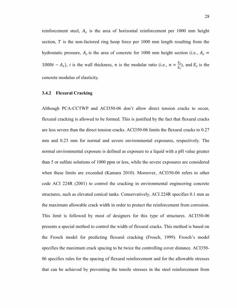
These maximum allowable stresses are provided for non-compression controlled sections
and are presented by Equations 3.7a and 3.7b.
For normal exposures,
√ (
⁄ ) (3.7.a)
, for one-way members
, for two-way members
For severe exposures,
√ (
⁄ ) (3.7.b)
, for one-way members
, for two-way members
Where, fsmax is the maximum allowable steel stress (MPa), S is the bar spacing (mm), db is
the bar diameter (mm), is the strain gradient amplification factor = 1.2 for a wall
thickness ≥ 400mm and 1.35 for awall thickness < 400mm, and fs is the calculated
stress in reinforcement at service loads (MPa), it can be calculated as the service moment
divided by the product of steel area and internal moment arm, as shown in Equation 3.8.
The steps to calculate the stress in reinforcement are shown in Equations 3.8 to 3.12.
(3.8)
31
(3.9)
√ ( (3.10)
(3.11)
(3.12)
Where, is the service moment resulting from the applied loads (i.e., unfactored
moment), is area of flexural reinforcement, is steel ratio, section width (
), is the modular ratio
, is the modulus of elasticity of flexural
reinforcing steel, is the concrete modulus of elasticity, and is bar diameter.
3.5 Design Approach
The design of liquid containing tanks is generally governed by the serviceability
requirements, including durability and leakage. Basically, the philosophy of serviceability
limit state is to minimize the stresses applied on the reinforcing steel. This can be
achieved by using the working stress approach. However, most of recent design codes are
based on the ultimate strength approach. Consequently, ACI350-06 introduced the
environmental durability factor as an additional load factor used for liquid retaining
structures. This factor enables the designers to achieve the serviceability requirements
through providing a sufficient amount of reinforcement steel.
31
3.5.1 Environmental Durability Factor
The last publication of PCA-CCTWP, which complies with the requirements of the old
version of ACI350 (1989), requires that the lateral liquid pressure shall be multiplied by a
load factor of 1.7. Moreover, sanitary durability factor (i.e., 1.65 for axial tension and 1.3
for flexural) should be provided to reduce the cracks, leading to a more conservative
design. However, the last publication of ACI350-06, which is applied in this research,
uses a load factor of 1.4 instead of 1.7 for both hydrostatic and dead loads. In addition, an
environmental durability factor Sd should be utilized. This factor is essential to reduce the
stresses in the reinforcement steel, leading to fewer cracks. Consequently, durability and
long term service life required for reinforced concrete conical tanks can be achieved. On
the other hand, ACI350-06 does not recommend to apply the environmental durability
factor for compression controlled sections since compression controlled members are
subjected to lower tensile stress and associated low strain (i.e., less than or equal to
0.002), and the cracks are in minor concern. According to the ACI350-06, the strength of
concrete should be greater than Sd·U, where U is the factored loads. The environmental
durability factor Sd can be calculated from Equation 3.13.
(3.13)
Where is the strength reduction factor, ( for both hoop tension and flexural
members), is the steel yield strength, is the allowable stress in normal
environment, and
, in case of hydrostatic pressure and dead
loads.
32
3.5.2 Wall Thickness
A reasonable wall thickness is required to satisfy the strength requirements, the allowed
crack width, concrete cover and ease of construction. Based on the recommendations of
PCA-CCTWP, which prevent forming of direct tension cracks, the wall thickness can be
estimated using Equation 3.14, considering 1000 mm width of the wall.
(3.14)
Where is the allowable concrete tensile strength ( ),
is the concrete
compressive strength, is the allowable stress in hoop tension ( ), is the
coefficient of shrinkage ( , is the modulus of elasticity of horizontal
reinforcing steel, is the non-factored ring hoop force per 1000 mm length resulting
from the hydrostatic pressure, is the modular ratio
, and is the concrete
modulus of elasticity, (PCA-CCTWP, 1993).
Although several codes, such as BS2007, do not specify a minimum wall thickness,
ACI350-06 provides a minimum thickness of 300 mm for walls equal to or higher than
3 m. The required concrete volume and the overweight of the wall depend on the
minimum wall thickness required for constructability.
3.5.3 Wall Reinforcement
Since the tank walls are subjected to two types of stresses, including hoop tension
stresses and meridional stresses, it is required to provide sufficient reinforcing steel for
33
both circumferential and longitudinal directions. Moreover, selection of bar diameter and
distribution of reinforcements is important to design a leak free tank.
The horizontal reinforcement steel (i.e., circumferential reinforcement) is required to
resist all hoop tension forces resulting from the hydrostatic pressure. According to PCA-
CCTWP, the area of circumferential steel can be specified from the following expression
(
), where is the maximum factored hoop tension force magnified by the
environmental durability factor , ( , where is the service hoop
tension obtained from the analysis method, and is the steel yielding strength. It should
be noted that the required area of horizontal steel should not be less than the minimum
specified area ( ), for walls without joints (ACI350, 2006).
Moreover, vertical reinforcement (i.e., longitudinal reinforcement) is provided to carry
the forces applied on the horizontal segment of the wall. In cylindrical tanks, PCA-
CCTWP specifies the vertical reinforcement to resist the flexural moment resulting from
the hydrostatic pressure ignoring the compression normal force due to wall self-weight.
In case of conical tanks, the vertical reinforcement resists both flexural moment and
compression normal force, which has a large value compared to cylindrical tanks. That is
related to the inclination of the vessel wall. Hence, the circumferential segment of the
conical shaped tanks is to be designed as a compression member. These compression
normal forces have a confinement effect which leads to a reduction in the crack width
initiated in the circumferential segment. In such cases, check for crack width can be
neglected except if the section is under large flexural moment compared to a small
normal compression force. ACI350-06 requires a minimum vertical reinforcement for the
34
wall to be ( ), where is the concrete gross area and can be simplified to
( ) for 1000 mm width section.
3.6 Parametric Study
Selection of an appropriate method for the analysis of liquid-filled reinforced concrete
conical tanks is extremely important in order to determine the internal forces acting on
the tank’s wall. Two analysis tools, as previously presented, are available; the first is
PCA-CCTWP and the second is FEA. The simplified approach presented by PCA-
CCTWP can be used exclusively or as a preliminary design in order to determine the
initial wall thickness and the internal forces developed in the tank wall due to hydrostatic
pressure. The initial thickness obtained from PCA-CCTWP can be utilized in FEA
models to predict the actual behaviour. This section presents a parametric study that is
conducted to compare the two methods and to evaluate the discrepancy that may exist
due to analysis assumptions and approximations in the approach used to transfer from a
conical shape to an equivalent cylinder. The findings of this parametric study assist to
understand the behaviour of reinforced concrete conical tanks under hydrostatic pressure.
In the first step of this parametric study, all studied conical tanks are transformed to
equivalent cylinders using the AWWA-D100 (2005) procedure. The wall thickness of
each equivalent cylindrical tank is then designed to comply with the requirements of
PCA-CCTWP. The maximum forces (i.e., hoop tension and meridional moment) are
obtained. In the second step, the designed thickness of the equivalent cylinder is used in
the finite element analysis to model the conical tank in order to predict the maximum
internal forces which are compared with those obtained from PCA-CCTWP. Finally, the
35
wall sections which are designed according to the forces resulting from the PCA-
CCTWP, are checked under the effect of the internal forces obtained from the finite
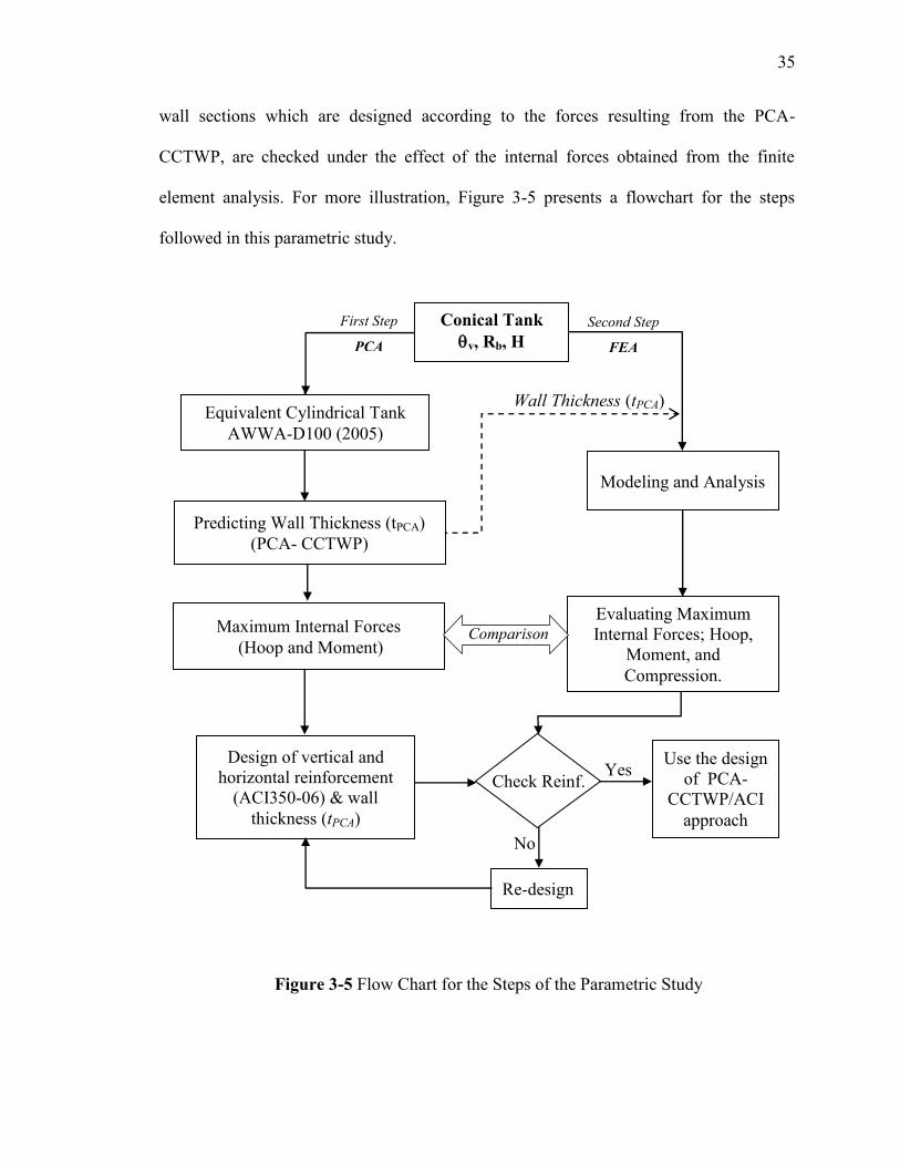
element analysis. For more illustration, Figure 3-5 presents a flowchart for the steps
followed in this parametric study.
Figure 2-5 Flow Chart for the Steps of the Parametric Study
Maximum Internal Forces
(Hoop and Moment)
First Step
PCA
Second Step
FEA
Modeling and Analysis
Yes
No
Re-design
Use the design
of PCA-
CCTWP/ACI
approach
Wall Thickness (tPCA) Equivalent Cylindrical Tank
AWWA-D100 (2005)
Check Reinf.
Design of vertical and
horizontal reinforcement
(ACI350-06) & wall
thickness (tPCA)
Conical Tank
v, Rb, H
Predicting Wall Thickness (tPCA)
(PCA- CCTWP)
Evaluating Maximum
Internal Forces; Hoop,
Moment, and
Compression.
Comparison
Figure 3-5 Flow Chart for the Steps of the Parametric Study
36
3.6.1 Assumptions for Analysis and Design
The study focuses on the behaviour of reinforced concrete tanks that have a pure conical
shape. The walls of these tanks are assumed to be simply supported at the base while they
are free on the top. The wall thickness is considered as constant along its height and
designed according to the requirements of PCA-CCTWP. The tanks are analyzed under
the hydrostatic loads resulting from the liquid weight. This liquid is assumed to be water
and fully fill the tank vessel. The own weight of the tank vessel is not considered in the
FEA model since it is ignored by the PCA-CCTWP method. Also, linear elastic
behaviour of the material is assumed in both cases as the design of liquid tanks has to
satisfy serviceability requirements by preventing cracks from initiating at any location of
the concrete section. The dimensions and properties of the tanks in concern are chosen to
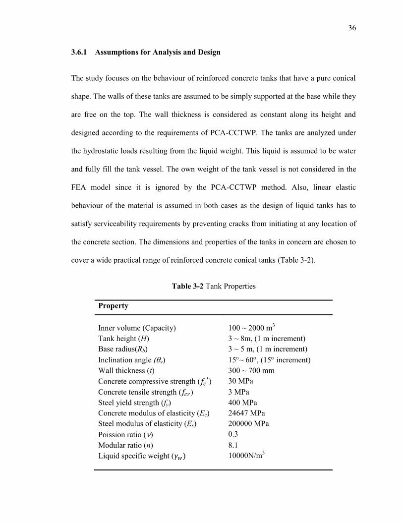
cover a wide practical range of reinforced concrete conical tanks (Table 3-2).
Table 3-2 Tank Properties
Property
Inner volume (Capacity) 100 ~ 2000 m3
Tank height (H) 3 ~ 8m, (1 m increment)
Base radius(Rb) 3 ~ 5 m, (1 m increment)
Inclination angle (v) 15~ 60, (15 increment)
Wall thickness (t) 300 ~ 700 mm
Concrete compressive strength ( ) 30 MPa
Concrete tensile strength ( ) 3 MPa
Steel yield strength (fy) 400 MPa
Concrete modulus of elasticity (Ec) 24647 MPa
Steel modulus of elasticity (Es) 200000 MPa
Poission ratio () 0.3
Modular ratio (n) 8.1
Liquid specific weight ( 10000N/m3
37
3.6.2 Parametric Study Results
In this section, the results of the parametric study are presented. Such study is conducted
by considering 66 reinforced concrete conical tanks covering practical geometries with
different vessel capacities. This parametric study is used to assess the adequacy of
utilizing the code provisions used for cylindrical tanks when applied on conical shaped
tanks. This is done by checking the wall thickness as well as reinforcements in both
directions; horizontal and vertical that are obtained following code guidelines. Table 3-3
shows the maximum forces (i.e., hoop tension forces and meridional moments), required
thickness, and the designed section based on PCA-CCTWP method. It should be noted
that the thickness of the wall is mainly governed by the maximum hoop tension. Also, the
minimum flexural reinforcement satisfies the ultimate strength requirement.
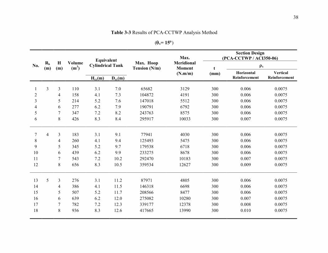
38
Table 3-3 Results of PCA-CCTWP Analysis Method
(v= 15)
No. Rb
(m)
H
(m)
Volume
(m3)
Equivalent
Cylindrical Tank Max. Hoop
Tension (N/m)
Max.
Meridional
Moment
(N.m/m)
Section Design
(PCA-CCTWP / ACI350-06)
t
(mm)
s
Horizontal
Reinforcement
Vertical
Reinforcement Hcy(m) Dcy(m)
1 3 3 110 3.1 7.0 65682 3129 300 0.006 0.0075
2 4 158 4.1 7.3 104872 4191 300 0.006 0.0075
3 5 214 5.2 7.6 147018 5512 300 0.006 0.0075
4 6 277 6.2 7.9 190791 6792 300 0.006 0.0075
5 7 347 7.2 8.2 243763 8575 300 0.006 0.0075
6 8 426 8.3 8.4 295917 10033 300 0.007 0.0075
7 4 3 183 3.1 9.1 77941 4030 300 0.006 0.0075
8 4 260 4.1 9.4 125493 5475 300 0.006 0.0075
9 5 345 5.2 9.7 179538 6718 300 0.006 0.0075
10 6 439 6.2 9.9 233275 8678 300 0.006 0.0075
11 7 543 7.2 10.2 292470 10183 300 0.007 0.0075
12 8 656 8.3 10.5 359534 12627 300 0.009 0.0075
13 5 3 276 3.1 11.2 87971 4805 300 0.006 0.0075
14 4 386 4.1 11.5 146318 6698 300 0.006 0.0075
15 5 507 5.2 11.7 208566 8477 300 0.006 0.0075
16 6 639 6.2 12.0 275082 10280 300 0.007 0.0075
17 7 782 7.2 12.3 339177 12378 300 0.008 0.0075
18 8 936 8.3 12.6 417665 13990 300 0.010 0.0075
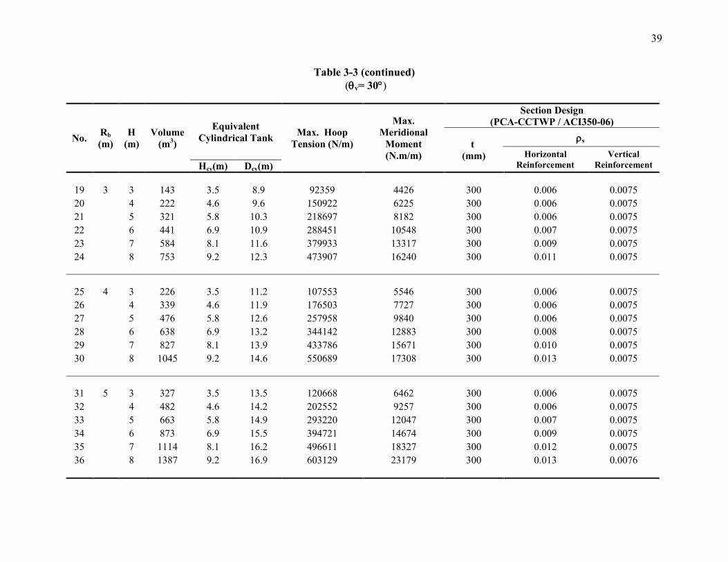
39
Table 3-3 (continued)
(v= 30)
No. Rb
(m)
H
(m)
Volume
(m3)
Equivalent
Cylindrical Tank Max. Hoop
Tension (N/m)
Max.
Meridional
Moment
(N.m/m)
Section Design
(PCA-CCTWP / ACI350-06)
t
(mm)
s
Horizontal
Reinforcement
Vertical
Reinforcement Hcy(m) Dcy(m)
19 3 3 143 3.5 8.9 92359 4426 300 0.006 0.0075
20 4 222 4.6 9.6 150922 6225 300 0.006 0.0075
21 5 321 5.8 10.3 218697 8182 300 0.006 0.0075
22 6 441 6.9 10.9 288451 10548 300 0.007 0.0075
23 7 584 8.1 11.6 379933 13317 300 0.009 0.0075
24 8 753 9.2 12.3 473907 16240 300 0.011 0.0075
25 4 3 226 3.5 11.2 107553 5546 300 0.006 0.0075
26 4 339 4.6 11.9 176503 7727 300 0.006 0.0075
27 5 476 5.8 12.6 257958 9840 300 0.006 0.0075
28 6 638 6.9 13.2 344142 12883 300 0.008 0.0075
29 7 827 8.1 13.9 433786 15671 300 0.010 0.0075
30 8 1045 9.2 14.6 550689 17308 300 0.013 0.0075
31 5 3 327 3.5 13.5 120668 6462 300 0.006 0.0075
32 4 482 4.6 14.2 202552 9257 300 0.006 0.0075
33 5 663 5.8 14.9 293220 12047 300 0.007 0.0075
34 6 873 6.9 15.5 394721 14674 300 0.009 0.0075
35 7 1114 8.1 16.2 496611 18327 300 0.012 0.0075
36 8 1387 9.2 16.9 603129 23179 300 0.013 0.0076

41
Table 3-3 (continued)
(v= 45)
No. Rb
(m)
H
(m)
Volume
(m3)
Equivalent
Cylindrical Tank Max. Hoop
Tension (N/m)
Max.
Meridional
Moment
(N.m/m)
Section Design
(PCA-CCTWP / ACI350-06)
t
(mm)
s
Horizontal
Reinforcement
Vertical
Reinforcement Hcy(m) Dcy(m)
37 3 3 198 4.2 12.7 163656 7703 300 0.006 0.0075
38 4 331 5.7 14.1 273859 11188 300 0.007 0.0075
39 5 508 7.1 15.6 405426 15153 300 0.010 0.0075
40 6 735 8.5 17.0 548074 19987 300 0.013 0.0075
41 7 1019 9.9 18.4 697752 29628 350 0.016 0.0078
42 8 1366 11.3 19.8 858525 44280 425 0.014 0.0081
43 4 3 292 4.2 15.6 188238 9394 300 0.006 0.0075
44 4 469 5.7 17 312339 13577 300 0.007 0.0075
45 5 696 7.1 18.4 464477 17516 300 0.011 0.0075
46 6 980 8.5 19.8 624659 24992 320 0.014 0.0076
47 7 1327 9.9 21.2 788408 37378 380 0.015 0.0079
48 8 1743 11.3 22.6 957249 57412 480 0.014 0.0082
49 5 3 405 4.2 18.4 208578 10980 300 0.006 0.0075
50 4 633 5.7 19.8 350294 15894 300 0.008 0.0075
51 5 916 7.1 21.2 514717 20153 310 0.012 0.0076
52 6 1263 8.5 22.6 675038 33226 380 0.013 0.0079
53 7 1679 9.9 24 839095 51956 480 0.012 0.0082
54 8 2170 11.3 25.5 1030823 70964 550 0.013 0.0083
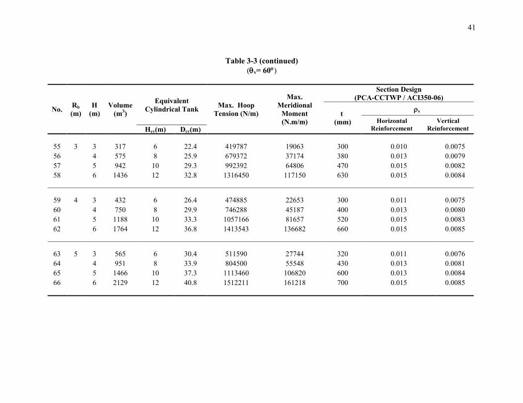
41
Table 3-3 (continued)
(v= 60)
No. Rb
(m)
H
(m)
Volume
(m3)
Equivalent
Cylindrical Tank Max. Hoop
Tension (N/m)
Max.
Meridional
Moment
(N.m/m)
Section Design
(PCA-CCTWP / ACI350-06)
t
(mm)
s
Horizontal
Reinforcement
Vertical
Reinforcement Hcy(m) Dcy(m)
55 3 3 317 6 22.4 419787 19063 300 0.010 0.0075
56 4 575 8 25.9 679372 37174 380 0.013 0.0079
57 5 942 10 29.3 992392 64806 470 0.015 0.0082
58 6 1436 12 32.8 1316450 117150 630 0.015 0.0084
59 4 3 432 6 26.4 474885 22653 300 0.011 0.0075
60 4 750 8 29.9 746288 45187 400 0.013 0.0080
61 5 1188 10 33.3 1057166 81657 520 0.015 0.0083
62 6 1764 12 36.8 1413543 136682 660 0.015 0.0085
63 5 3 565 6 30.4 511590 27744 320 0.011 0.0076
64 4 951 8 33.9 804500 55548 430 0.013 0.0081
65 5 1466 10 37.3 1113460 106820 600 0.013 0.0084
66 6 2129 12 40.8 1512211 161218 700 0.015 0.0085
42
In the FEA method, the selected conical tanks are modeled using the consistent shell
element described in the previous section. The wall thickness is assumed following PCA-
CCTWP (1993) code design provisions. The internal forces acting on the wall are
obtained, including hoop tension force, meridional moment and meridional normal
compression force. The tank wall, which was previously designed by the PCA-CCTWP,
is checked under the forces predicted by the FEA. Table 3-4 summarizes the maximum
internal forces obtained from FEA. Moreover, it shows the results of the checked wall
sections for both serviceability and ultimate strength requirements.
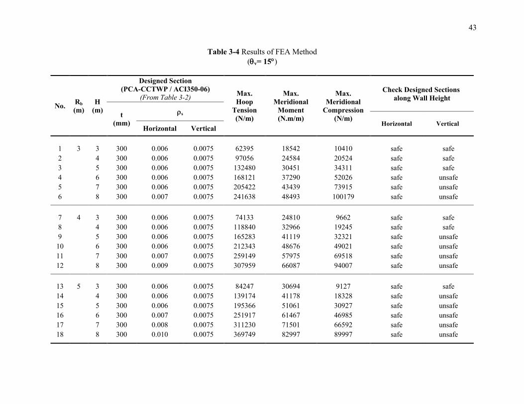
43
Table 3-4 Results of FEA Method
(v= 15)
No. Rb
(m)
H
(m)
Designed Section
(PCA-CCTWP / ACI350-06)
(From Table 3-2) Max.
Hoop
Tension
(N/m)
Max.
Meridional
Moment
(N.m/m)
Max.
Meridional
Compression
(N/m)
Check Designed Sections
along Wall Height
t
(mm)
s
Horizontal Vertical Horizontal Vertical
1 3 3 300 0.006 0.0075 62395 18542 10410 safe safe
2 4 300 0.006 0.0075 97056 24584 20524 safe safe
3 5 300 0.006 0.0075 132480 30451 34311 safe safe
4 6 300 0.006 0.0075 168121 37290 52026 safe unsafe
5 7 300 0.006 0.0075 205422 43439 73915 safe unsafe
6 8 300 0.007 0.0075 241638 48493 100179 safe unsafe
7 4 3 300 0.006 0.0075 74133 24810 9662 safe safe
8 4 300 0.006 0.0075 118840 32966 19245 safe safe
9 5 300 0.006 0.0075 165283 41119 32321 safe unsafe
10 6 300 0.006 0.0075 212343 48676 49021 safe unsafe
11 7 300 0.007 0.0075 259149 57975 69518 safe unsafe
12 8 300 0.009 0.0075 307959 66087 94007 safe unsafe
13 5 3 300 0.006 0.0075 84247 30694 9127 safe safe
14 4 300 0.006 0.0075 139174 41178 18328 safe unsafe
15 5 300 0.006 0.0075 195366 51061 30927 safe unsafe
16
6 300 0.007 0.0075 251917 61467 46985 safe unsafe
17 7 300 0.008 0.0075 311230 71501 66592 safe unsafe
18 8 300 0.010 0.0075 369749 82997 89997 safe unsafe
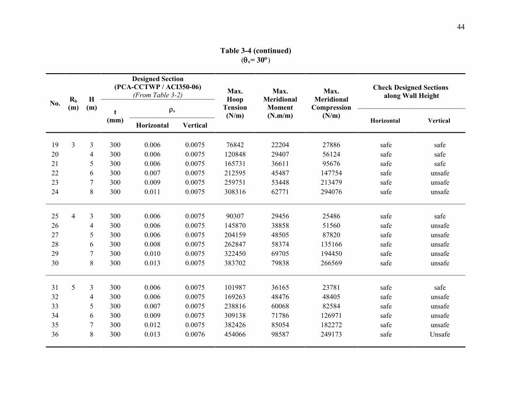
44
Table 3-4 (continued)
(v= 30)
No. Rb
(m)
H
(m)
Designed Section
(PCA-CCTWP / ACI350-06)
(From Table 3-2) Max.
Hoop
Tension
(N/m)
Max.
Meridional
Moment
(N.m/m)
Max.
Meridional
Compression
(N/m)
Check Designed Sections
along Wall Height
t
(mm)
s
Horizontal Vertical Horizontal Vertical
19 3 3 300 0.006 0.0075 76842 22204 27886 safe safe
20 4 300 0.006 0.0075 120848 29407 56124 safe safe
21 5 300 0.006 0.0075 165731 36611 95676 safe safe
22 6 300 0.007 0.0075 212595 45487 147754 safe unsafe
23 7 300 0.009 0.0075 259751 53448 213479 safe unsafe
24 8 300 0.011 0.0075 308316 62771 294076 safe unsafe
25 4 3 300 0.006 0.0075 90307 29456 25486 safe safe
26 4 300 0.006 0.0075 145870 38858 51560 safe unsafe
27 5 300 0.006 0.0075 204159 48505 87820 safe unsafe
28 6 300 0.008 0.0075 262847 58374 135166 safe unsafe
29 7 300 0.010 0.0075 322450 69705 194450 safe unsafe
30 8 300 0.013 0.0075 383702 79838 266569 safe unsafe
31 5 3 300 0.006 0.0075 101987 36165 23781 safe safe
32 4 300 0.006 0.0075 169263 48476 48405 safe unsafe
33
5 300 0.007 0.0075 238816 60068 82584 safe unsafe
34 6 300 0.009 0.0075 309138 71786 126971 safe unsafe
35 7 300 0.012 0.0075 382426 85054 182272 safe unsafe
36 8 300 0.013 0.0076 454066 98587 249173 safe Unsafe
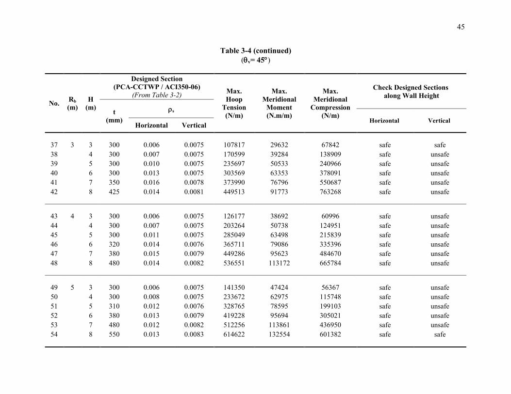
45
Table 3-4 (continued)
(v= 45)
No. Rb
(m)
H
(m)
Designed Section
(PCA-CCTWP / ACI350-06)
(From Table 3-2) Max.
Hoop
Tension
(N/m)
Max.
Meridional
Moment
(N.m/m)
Max.
Meridional
Compression
(N/m)
Check Designed Sections
along Wall Height
t
(mm)
s
Horizontal Vertical Horizontal Vertical
37 3 3 300 0.006 0.0075 107817 29632 67842 safe safe
38 4 300 0.007 0.0075 170599 39284 138909 safe unsafe
39 5 300 0.010 0.0075 235697 50533 240966 safe unsafe
40 6 300 0.013 0.0075 303569 63353 378091 safe unsafe
41 7 350 0.016 0.0078 373990 76796 550687 safe unsafe
42 8 425 0.014 0.0081 449513 91773 763268 safe unsafe
43 4 3 300 0.006 0.0075 126177 38692 60996 safe unsafe
44 4 300 0.007 0.0075 203264 50738 124951 safe unsafe
45 5 300 0.011 0.0075 285049 63498 215839 safe unsafe
46 6 320 0.014 0.0076 365711 79086 335396 safe unsafe
47 7 380 0.015 0.0079 449286 95623 484670 safe unsafe
48 8 480 0.014 0.0082 536551 113172 665784 safe unsafe
49 5 3 300 0.006 0.0075 141350 47424 56367 safe unsafe
50 4 300 0.008 0.0075 233672 62975 115748 safe unsafe
51
5 310 0.012 0.0076 328765 78595 199103 safe unsafe
52 6 380 0.013 0.0079 419228 95694 305021 safe unsafe
53 7 480 0.012 0.0082 512256 113861 436950 safe unsafe
54 8 550 0.013 0.0083 614622 132554 601382 safe safe
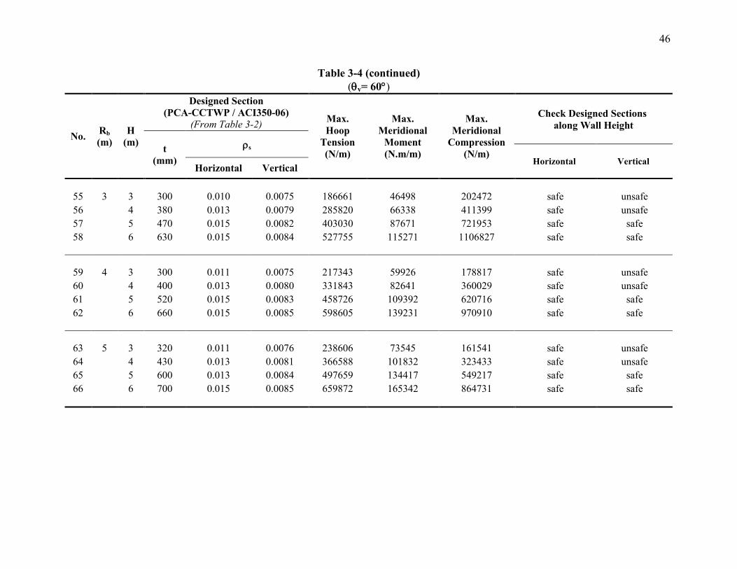
46
Table 3-4 (continued)
(v= 60)
No. Rb
(m)
H
(m)
Designed Section
(PCA-CCTWP / ACI350-06)
(From Table 3-2) Max.
Hoop
Tension
(N/m)
Max.
Meridional
Moment
(N.m/m)
Max.
Meridional
Compression
(N/m)
Check Designed Sections
along Wall Height
t
(mm)
s
Horizontal Vertical Horizontal Vertical
55 3 3 300 0.010 0.0075 186661 46498 202472 safe unsafe
56 4 380 0.013 0.0079 285820 66338 411399 safe unsafe
57 5 470 0.015 0.0082 403030 87671 721953 safe safe
58 6 630 0.015 0.0084 527755 115271 1106827 safe safe
59 4 3 300 0.011 0.0075 217343 59926 178817 safe unsafe
60 4 400 0.013 0.0080 331843 82641 360029 safe unsafe
61 5 520 0.015 0.0083 458726 109392 620716 safe safe
62 6 660 0.015 0.0085 598605 139231 970910 safe safe
63 5 3 320 0.011 0.0076 238606 73545 161541 safe unsafe
64
4 430 0.013 0.0081 366588 101832 323433 safe unsafe
65 5 600 0.013 0.0084 497659 134417 549217 safe safe
66 6 700 0.015 0.0085 659872 165342 864731 safe safe
47
For more illustration, the vertical section is checked under the effect of hoop tension that
is predicted by the FEA model. In order to achieve the adequate wall thickness, the
following conditions have to be satisfied;
( ( ( , and
( (
( ( (
.
Where ( is the area of horizontal reinforcement required to resist the hoop tension
predicted by FEA, (
, (Tu)FEA is the factored hoop tension, and is the
steel yield strength, ( is the horizontal reinforcing steel required to resist the hoop
tension obtained from PCA-CCTWP.
The design requirements (i.e., ultimate strength and serviceability) for different
horizontal sections along the wall are checked. Interaction diagrams are developed for the
designed sections which are subjected to a combined bending and high axial load, while
sectional analysis is performed for wall sections that are mainly governed by flexural
moments. Based on the constructability aspects, the section is assumed to have the same
vertical reinforcement for both sides (i.e., external and internal faces of the tank's wall).
Serviceability is controlled by preventing the tensile stresses in the steel reinforcement
from exceeding the maximum allowable stresses specified by ACI350-06. Figure 3-6
presents a typical distribution for meridional moment and meridional normal compression
along the wall height of tank No. 52 while Figure 3-7 shows the related interaction
diagram.

48
Figure 2-6 Distribution diagram of the meridional moment and
axial compression for tank #52 (v=45, Rb=5m, H=6m)
0 50 100 150 200 250 300 350
0
1
2
3
4
5
6
0 20 40 60 80 100
Meridional Compression Force (kN)
Wa
ll H
eig
ht
(m)
Meridional Moment (kN.m)
FEA-Meridional Moment
FEA-Meridional Compression Force
Figure 2-7 Distribution diagram of the meridional moment
and axial compression for tank #52 (v=45, Rb=5m, H=6m)
s= 0.79% is the ratio of vertical reinforcement
-2000
-1000
0
1000
2000
3000
4000
5000
6000
7000
0 50 100 150 200 250 300 350
Nu
(k
N)
Mu (kN.m)
Meridional Compression Force (kN/m)
Meridional Moment (kN.m/m)
Nu
(k
N/m
)
Mu (kN.m/m)
Figure 3-6 Distribution diagram of the meridional moment and
axial compression for tank #52 (v=45, Rb=5m, H=6m)
Figure 3-7 Interaction Diagram for tank #52 (v=45, Rb=5m, H=6m)
s= 0.79% is the ratio of vertical reinforcement
49
3.6.2.1 Comparison between PCA-CCTWP and FEA Results
This subsection provides a comparison between the two analysis methods used in the
current study (i.e., PCA-CCTWP, and FEA). This comparison is presented in order to
evaluate the adequacy of applying code provisions in case of conical tanks.
Based on the results obtained from both PCA-CCTWP and FEA, it is noticed that the
internal forces (i.e., hoop tension, meridional moment, and meridional normal force)
increase as the angle of wall inclination increases, leading to a larger required wall
thickness. For example, the thickness of broad conical tanks (i.e., v ≥ 45°) ranging
between 400 mm to 600 mm, and reaches up to 700 mm for tank No. 66. On the other
hand, the minimum wall thickness specified by PCA-CCTWP and ACI350-06 (i.e., 300
mm) is found to be sufficient for serviceability requirements for a wide range of narrow
conical tanks (i.e., v 45°). The same trend is observed by increasing the tank height
and base radius. It can be also noticed that the meridional compression force obtained
from FEA decreases as the base radius increases because the hydrostatic pressure is
distributed over a larger circumferential area.
The internal forces obtained from PCA-CCTWP are compared with FEA in order to
evaluate the range of discrepancies. Table 3-5 presents the differences between the
maximum forces, including hoop tension forces and meridional moments for the all 66
studied tanks. It should be mentioned that the meridional compression is excluded from
the comparison because PCA-CCTWP ignores the compression developed by the wall
51
own weight in case of cylindrical tanks. It is noticed that PCA-CCTWP method results in
maximum hoop tension forces that are greater than those obtained from FEA. The range
of discrepancy between the two approaches depends on the angle of inclination of the
wall, base radius and tank height. Typically, the maximum hoop obtained from both
methods is located between the bottom third and bottom fifth region of the wall height.
For hoop tension distribution along wall height, a typical agreement is found for short-
narrow tanks having small inclination angles (i.e., v 45°, H 5m). On the other hand,
there are disagreements for the hoop values along wall height of tall-wide conical tanks.
This can be related to the fact that as the inclination angle decreases; the behaviour of the
conical tank is closer to be cylindrical. Figure 3-8 shows a typical distribution diagram
for hoop tension predicted by the two methods for a short-narrow conical tank while
Figure 3-9 presents the hoop diagram of a tall-wide tank.
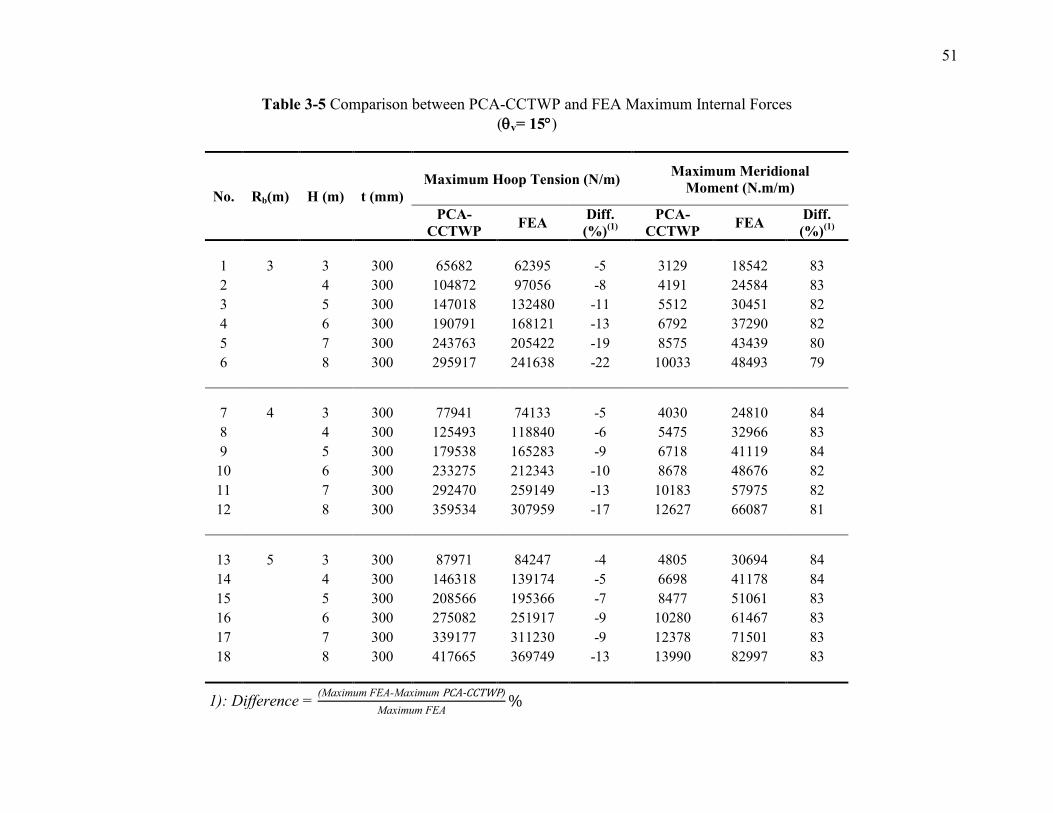
51
Table 3-5 Comparison between PCA-CCTWP and FEA Maximum Internal Forces
(v= 15)
No. Rb(m) H (m) t (mm)
Maximum Hoop Tension (N/m) Maximum Meridional
Moment (N.m/m)
PCA-
CCTWP FEA
Diff.
(%)(1)
PCA-
CCTWP FEA
Diff.
(%)(1)
1 3 3 300 65682 62395 -5 3129 18542 83
2 4 300 104872 97056 -8 4191 24584 83
3 5 300 147018 132480 -11 5512 30451 82
4 6 300 190791 168121 -13 6792 37290 82
5 7 300 243763 205422 -19 8575 43439 80
6 8 300 295917 241638 -22 10033 48493 79
7 4 3 300 77941 74133 -5 4030 24810 84
8 4 300 125493 118840 -6 5475 32966 83
9 5 300 179538 165283 -9 6718 41119 84
10 6 300 233275 212343 -10 8678 48676 82
11 7 300 292470 259149 -13 10183 57975 82
12 8 300 359534 307959 -17 12627 66087 81
13 5 3 300 87971 84247 -4 4805 30694 84
14 4 300 146318 139174 -5 6698 41178 84
15 5 300 208566 195366 -7 8477 51061 83
16 6 300 275082 251917 -9 10280 61467 83
17 7 300 339177 311230 -9 12378 71501 83
18 8 300 417665 369749 -13 13990 82997 83
1): Difference = x - x -
x
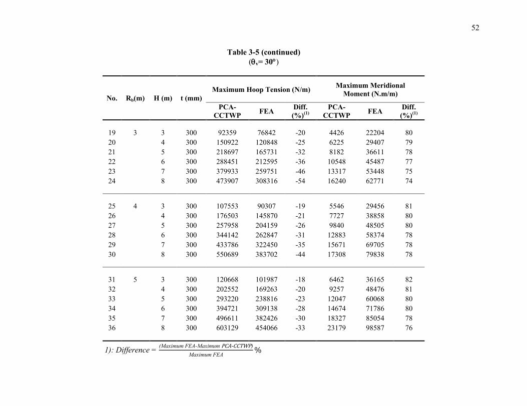
52
Table 3-5 (continued)
(v= 30)
No. Rb(m) H (m) t (mm)
Maximum Hoop Tension (N/m) Maximum Meridional
Moment (N.m/m)
PCA-
CCTWP FEA
Diff.
(%)(1)
PCA-
CCTWP FEA
Diff.
(%)(1)
19 3 3 300 92359 76842 -20 4426 22204 80
20 4 300 150922 120848 -25 6225 29407 79
21 5 300 218697 165731 -32 8182 36611 78
22 6 300 288451 212595 -36 10548 45487 77
23 7 300 379933 259751 -46 13317 53448 75
24 8 300 473907 308316 -54 16240 62771 74
25 4 3 300 107553 90307 -19 5546 29456 81
26 4 300 176503 145870 -21 7727 38858 80
27 5 300 257958 204159 -26 9840 48505 80
28 6 300 344142 262847 -31 12883 58374 78
29 7 300 433786 322450 -35 15671 69705 78
30 8 300 550689 383702 -44 17308 79838 78
31 5 3 300 120668 101987 -18 6462 36165 82
32 4 300 202552 169263 -20 9257 48476 81
33 5 300 293220 238816 -23 12047 60068 80
34 6 300 394721 309138 -28 14674 71786 80
35 7 300 496611 382426 -30 18327 85054 78
36 8 300 603129 454066 -33 23179 98587 76
1): Difference = x - x -
x

53
Table 3-5 (continued)
(v= 45)
No. Rb(m) H (m) t (mm)
Maximum Hoop Tension (N/m) Maximum Meridional
Moment (N.m/m)
PCA-
CCTWP)
FEA
Diff.
(%)(1)
PCA-
CCTWP FEA
Diff.
(%)(1)
37 3 3 300 163656 107817 -52 7703 29632 74
38 4 300 273859 170599 -61 11188 39284 72
39 5 300 405426 235697 -72 15153 50533 70
40 6 300 548074 303569 -81 19987 63353 68
41 7 350 697752 373990 -87 29628 76796 61
42 8 425 858525 449513 -91 44280 91773 52
43 4 3 300 188238 126177 -49 9394 38692 76
44 4 300 312339 203264 -54 13577 50738 73
45 5 300 464477 285049 -63 17516 63498 72
46 6 320 624659 365711 -71 24992 79086 68
47 7 380 788408 449286 -75 37378 95623 61
48 8 480 957249 536551 -78 57412 113172 49
49 5 3 300 208578 141350 -48 10980 47424 77
50 4 300 350294 233672 -50 15894 62975 75
51 5 310 514717 328765 -57 20153 78595 74
52 6 380 675038 419228 -61 33226 95694 65
53 7 480 839095 512256 -64 51956 113861 54
54 8 550 1030823 614622 -68 70964 132554 46
1): Difference = x - x -
x
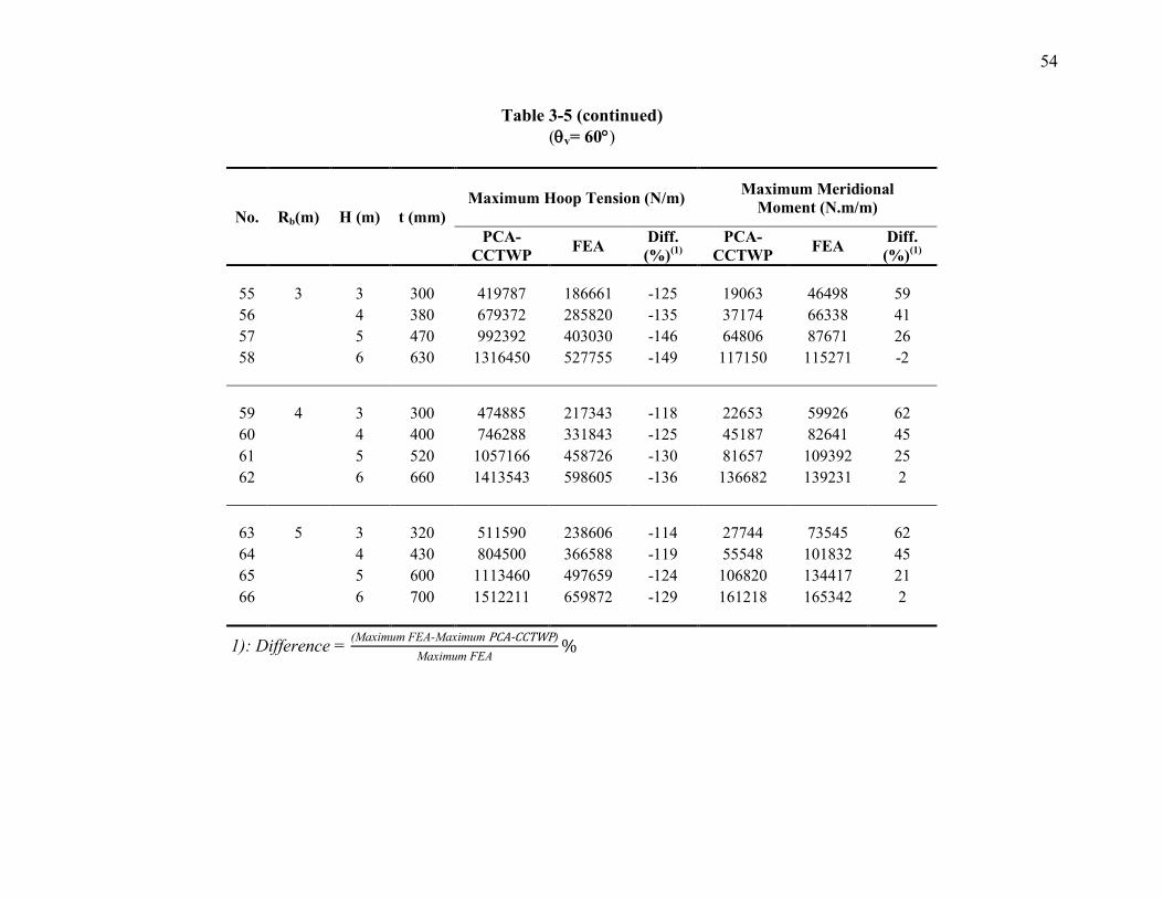
54
Table 3-5 (continued)
(v= 60)
No. Rb(m) H (m) t (mm)
Maximum Hoop Tension (N/m) Maximum Meridional
Moment (N.m/m)
PCA-
CCTWP FEA
Diff.
(%)(1)
PCA-
CCTWP FEA
Diff.
(%)(1)
55 3 3 300 419787 186661 -125 19063 46498 59
56 4 380 679372 285820 -135 37174 66338 41
57 5 470 992392 403030 -146 64806 87671 26
58 6 630 1316450 527755 -149 117150 115271 -2
59 4 3 300 474885 217343 -118 22653 59926 62
60 4 400 746288 331843 -125 45187 82641 45
61 5 520 1057166 458726 -130 81657 109392 25
62 6 660 1413543 598605 -136 136682 139231 2
63 5 3 320 511590 238606 -114 27744 73545 62
64 4 430 804500 366588 -119 55548 101832 45
65 5 600 1113460 497659 -124 106820 134417 21
66 6 700 1512211 659872 -129 161218 165342 2
1): Difference = x - x -
x
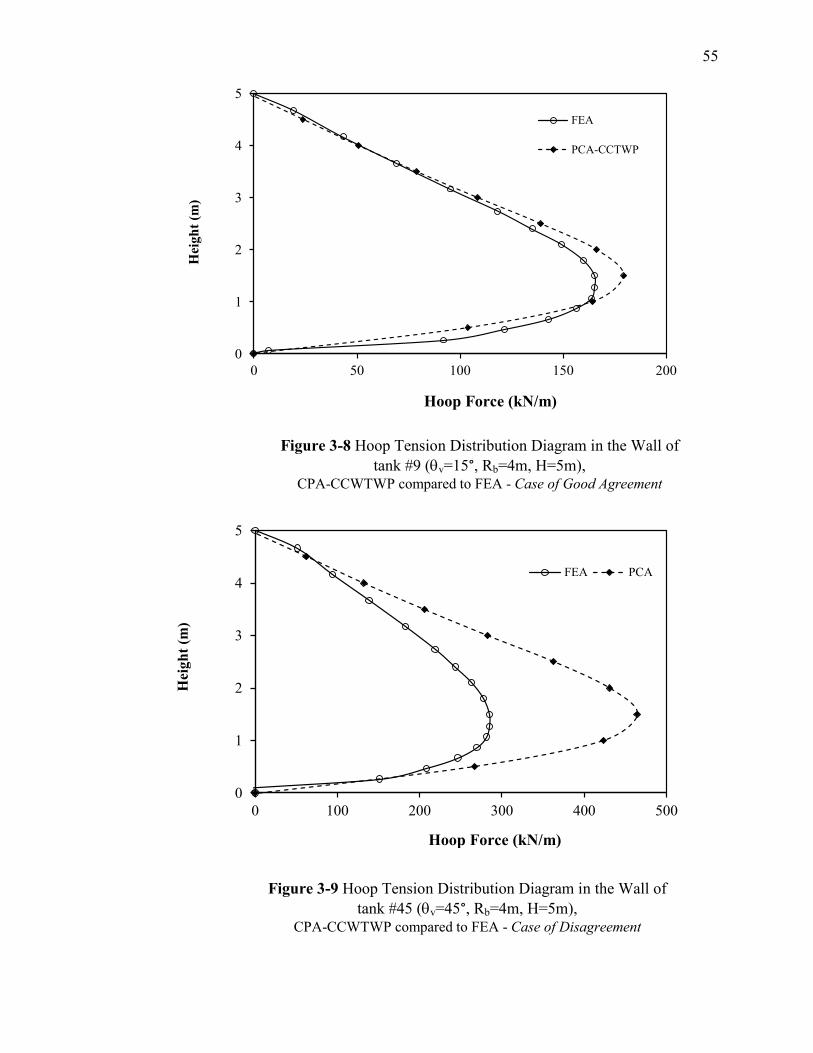
55
0
1
2
3
4
5
0 50 100 150 200
Hei
gh
t (m
)
Hoop Force (kN)
FEA
PCA-CCTWP
Figure 2-8 Hoop Tension Distribution Diagram in the Wall of
tank #9 (v=15°, Rb=4m, H=5m), CPA-CCWTWP compared to FEA - Case of Good Agreement
0
1
2
3
4
5
0 100 200 300 400 500
Hei
gh
t (m
)
Hoop Force (kN)
FEA PCA
Figure 2-9 Hoop Tension Distribution Diagram in the Wall of
tank #45 (v=45°, Rb=4m, H=5m), CPA-CCWTWP compared to FEA - Case of Disagreement
Hoop Force (kN/m)
Hoop Force (kN/m)
Figure 3-8 Hoop Tension Distribution Diagram in the Wall of
tank #9 (v=15°, Rb=4m, H=5m), CPA-CCWTWP compared to FEA - Case of Good Agreement
Figure 3-9 Hoop Tension Distribution Diagram in the Wall of
tank #45 (v=45°, Rb=4m, H=5m), CPA-CCWTWP compared to FEA - Case of Disagreement
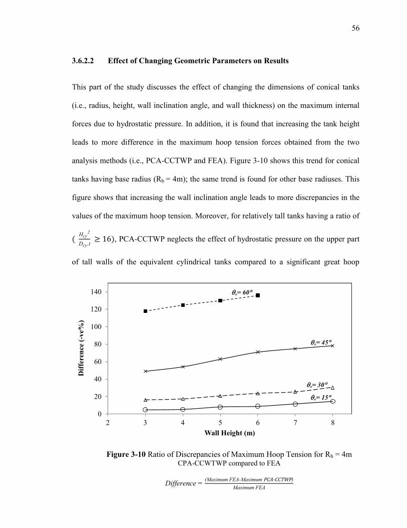
56
3.6.2.2 Effect of Changing Geometric Parameters on Results
This part of the study discusses the effect of changing the dimensions of conical tanks
(i.e., radius, height, wall inclination angle, and wall thickness) on the maximum internal
forces due to hydrostatic pressure. In addition, it is found that increasing the tank height
leads to more difference in the maximum hoop tension forces obtained from the two
analysis methods (i.e., PCA-CCTWP and FEA). Figure 3-10 shows this trend for conical
tanks having base radius (Rb = 4m); the same trend is found for other base radiuses. This
figure shows that increasing the wall inclination angle leads to more discrepancies in the
values of the maximum hoop tension. Moreover, for relatively tall tanks having a ratio of
(
, PCA-CCTWP neglects the effect of hydrostatic pressure on the upper part
of tall walls of the equivalent cylindrical tanks compared to a significant great hoop
0
20
40
60
80
100
120
140
2 3 4 5 6 7 8
Dif
fere
nce
(-v
e%)
Wall Height (m)
v= 60
v= 45
v= 30
v= 15
Figure 3-10 Ratio of Discrepancies of Maximum Hoop Tension for Rb = 4m CPA-CCWTWP compared to FEA
Difference = x - x -
x
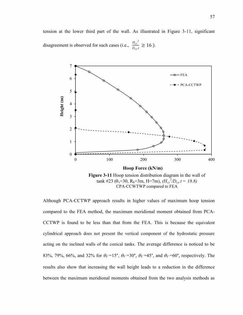
57
tension at the lower third part of the wall. As illustrated in Figure 3-11, significant
disagreement is observed for such cases (i.e.,
.
Although PCA-CCTWP approach results in higher values of maximum hoop tension
compared to the FEA method, the maximum meridional moment obtained from PCA-
CCTWP is found to be less than that from the FEA. This is because the equivalent
cylindrical approach does not present the vertical component of the hydrostatic pressure
acting on the inclined walls of the conical tanks. The average difference is noticed to be
83%, 79%, 66%, and 32% for V =15°, V =30°, V =45°, and V =60°, respectively. The
results also show that increasing the wall height leads to a reduction in the difference
between the maximum meridional moments obtained from the two analysis methods as
0
1
2
3
4
5
6
7
0 100 200 300 400
Hei
gh
t (m
)
Hoop Force (kN)
FEA
PCA-CCTWP
Figure 3-11 Hoop tension distribution diagram in the wall of
tank #23 (v=30, Rb=3m, H=7m), (Hcy2/Dcy.t = 18.8)
CPA-CCWTWP compared to FEA
Hoop Force (kN/m)
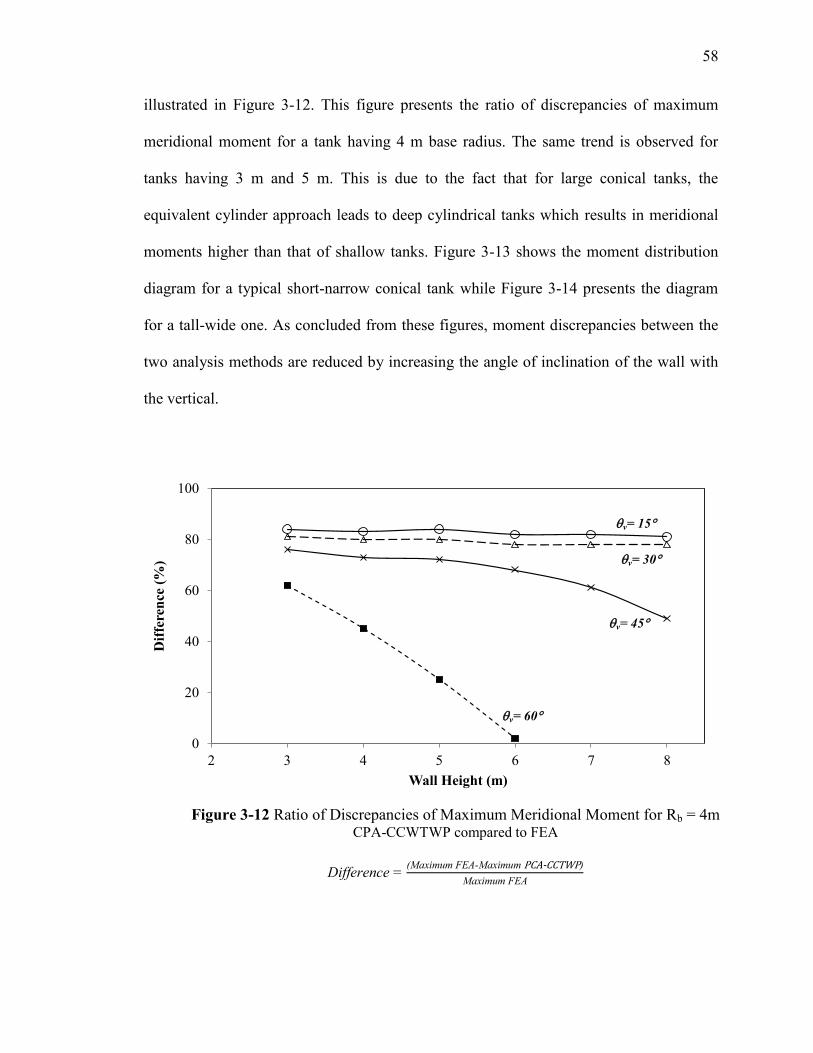
58
illustrated in Figure 3-12. This figure presents the ratio of discrepancies of maximum
meridional moment for a tank having 4 m base radius. The same trend is observed for
tanks having 3 m and 5 m. This is due to the fact that for large conical tanks, the
equivalent cylinder approach leads to deep cylindrical tanks which results in meridional
moments higher than that of shallow tanks. Figure 3-13 shows the moment distribution
diagram for a typical short-narrow conical tank while Figure 3-14 presents the diagram
for a tall-wide one. As concluded from these figures, moment discrepancies between the
two analysis methods are reduced by increasing the angle of inclination of the wall with
the vertical.
0
20
40
60
80
100
2 3 4 5 6 7 8
Dif
fere
nce
(%
)
Wall Height (m)
Figure 2-12 Ratio of Discrepancies of Maximum Meridional Moment for Rb = 4m CPA-CCWTWP compared to FEA
Difference = x - x -
x
v= 60
v= 45
v= 30
v= 15
Figure 3-12 Ratio of Discrepancies of Maximum Meridional Moment for Rb = 4m CPA-CCWTWP compared to FEA
Difference = x - x -
x
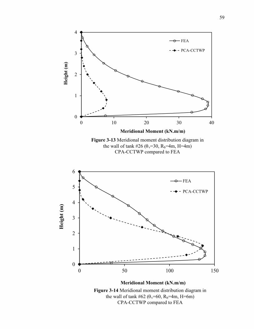
59
0
1
2
3
4
0 10 20 30 40
Hei
gh
t (m
)
Meridional Moment (kN.m)
FEA
PCA-CCTWP
Figure 3-13 Meridional moment distribution diagram in
the wall of tank #26 (v=30, Rb=4m, H=4m)
CPA-CCTWP compared to FEA
0
1
2
3
4
5
6
0 50 100 150
Heig
ht
(m)
Meridional Moment (kN.m)
FEA
PCA-CCTWP
Figure 3-14 Meridional moment distribution diagram in
the wall of tank #62 (v=60, Rb=4m, H=6m)
CPA-CCTWP compared to FEA
Meridional Moment (kN.m/m)
Meridional Moment (kN.m/m)
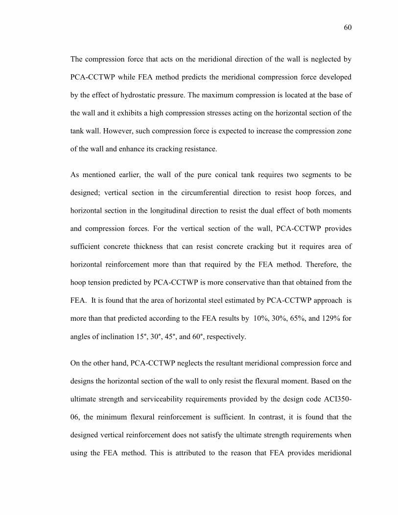
61
The compression force that acts on the meridional direction of the wall is neglected by
PCA-CCTWP while FEA method predicts the meridional compression force developed
by the effect of hydrostatic pressure. The maximum compression is located at the base of
the wall and it exhibits a high compression stresses acting on the horizontal section of the
tank wall. However, such compression force is expected to increase the compression zone
of the wall and enhance its cracking resistance.
As mentioned earlier, the wall of the pure conical tank requires two segments to be
designed; vertical section in the circumferential direction to resist hoop forces, and
horizontal section in the longitudinal direction to resist the dual effect of both moments
and compression forces. For the vertical section of the wall, PCA-CCTWP provides
sufficient concrete thickness that can resist concrete cracking but it requires area of
horizontal reinforcement more than that required by the FEA method. Therefore, the
hoop tension predicted by PCA-CCTWP is more conservative than that obtained from the
FEA. It is found that the area of horizontal steel estimated by PCA-CCTWP approach is
more than that predicted according to the FEA results by 10%, 30%, 65%, and 129% for
angles of inclination 15°, 30°, 45°, and 60°, respectively.
On the other hand, PCA-CCTWP neglects the resultant meridional compression force and
designs the horizontal section of the wall to only resist the flexural moment. Based on the
ultimate strength and serviceability requirements provided by the design code ACI350-
06, the minimum flexural reinforcement is sufficient. In contrast, it is found that the
designed vertical reinforcement does not satisfy the ultimate strength requirements when
using the FEA method. This is attributed to the reason that FEA provides meridional
61
compression forces and significant moments compared with those obtained from PCA-
CCTWP. Consequently, the horizontal section requires (2% to 180%) additional vertical
reinforcement compared to the PCA-CCTWP. This main conclusion proves the
inadequacy of applying code provisions used for cylindrical tanks on conical storage
vessels.
3.7 Conclusions
Based on the available codes of design, there are currently no guidelines to evaluate the
internal forces acting on the walls of elevated reinforced concrete conical tanks. These
codes provide guidelines only for rectangular and cylindrical tanks. PCA-CCTWP (1993)
provides a simplified approach for concrete cylindrical tanks. This approach is applied
for the selected conical tanks by using a special procedure specified by AWWA-D100
(2005) to convert these conical tanks to equivalent cylindrical tanks. Moreover, a built in-
house finite element model, which is based on a degenerated consistent sub-parametric
shell element, is employed to model the conical tanks. In this study, several reinforced
concrete conical tanks subjected to hydrostatic pressure are analyzed and designed. Based
on a parametric study conducted on 66 conical tanks having different configurations and
by comparing the internal forces in the walls of these tanks that are obtained from PCA-
CCTWP and FEA, the following conclusions can be drawn:
PCA-CCTWP provides higher maximum hoop tension than that obtained from
FEA models. The average difference is 10%, 30%, 65%, and 129% for wall
inclination angles v = 15°, v = 30°, v = 45°, andv = 60°, respectively. However,
62
the study shows that the results of hoop tension from PCA-CCTWP and FEA have
a good agreement for short-narrow tanks.
The maximum meridional moments obtained from PCA-CCTWP are less than that
predicted by FEA. The average range of disagreement is 32% to 83% depending on
the inclination angle and the wall height. It is noticed that as the inclination angle
and wall height increase the range of disagreement decreases. Therefore, there is an
agreement in maximum meridional moments obtained from PCA-CCTWP and
FEA in case of tall-wide conical tanks.
The wall minimum thickness specified by ACI350-06 (i.e., 300 mm) is found to be
sufficient for serviceability requirements for conical tanks having v 45°.
However, increasing wall inclination angle and tank height, especially for
leads to an increase in the required wall thickness in order to achieve
serviceability requirements.
For tall-wide reinforced concrete conical tanks (i.e., v ≥45°, H 5m), the designed
wall thickness using PCA-CCTWP method is found to be overestimated. This is
attributed to that PCA-CCTWP method provides higher hoop tension, leading to an
over conservative design. Consequently, wall thickness can be reduced without
affecting the serviceability requirement.
PCA-CCTWP method is mainly used to design tank walls to carry only hoop
tension and meridional moment. In case of conical tanks, a larger meridional
moment combined with high meridional compression, which is not presented in
PCA-CCTWP, are caused by the vertical component of the hydrostatic pressure
63
acting on the inclined walls of the tanks. This may lead to an inadequate design by
following the PCA-CCTWP approach.
64
4 CHAPTER 4
SIMPLIFIED DESIGN CHARTS FOR REINFORCED CONCRETE CONICAL
TANKS UNDER HYDROSTATIC LOADING
4.1 Introduction
Structural engineers usually seek a simple approach that satisfies all design requirements
to be utilized while designing complex structures. The design of a conical shaped tank is
considered as a challenging task because of the complication in the state of stresses and
the lack of direct guidelines for hydrostatically loaded reinforced concrete conical tanks
in codes of design. The design of steel liquid-storage structures in North America is
usually based on the specifications provided by either the American Water Works
Association AWWA-D100 (2005) or the American Petroleum Institute API 650 (2006).
Both specifications adopt an equivalent cylindrical tank approach in which the conical
segment is replaced by a cylindrical part. The main drawback of this approximation is
that it does not accurately simulate the state of stresses induced in the inclined walls of
the conical segment.
In chapter 3, the accuracy of a design approach for reinforced concrete conical tanks
which combines PCA-CCTWP provisions with the equivalent cylinder approach defined
by AWWA-D100 (2005) has been assessed. This assessment was done by conducting a
parametric study covering a practical range of conical tanks having different dimensions
and capacities. It was concluded that the proposed PCA-CCTWP approach leads to an
inadequate design if applied to conical tanks. It was also noticed that such approach
65
provides higher hoop tension and less meridional moment compared to those obtained
from FEA results.
In order to achieve the most economical and safe design of conical tanks, a
comprehensive finite element analysis combined with detailed design specifications is
essentially required. In performing the analysis of these tanks using the finite element
method, the resulting internal forces are predicted along both the meridional and
circumferential directions of the tanks’ walls. Shell elements are used to predict such
behaviour, which requires knowledge and expertise in sophisticated 3-D finite element
analysis. Accordingly, it is not an easy task for the designer to choose the adequate
thickness as well as to provide sufficient reinforcement for both circumferential direction
for tension hoop, and longitudinal direction for meridional moment and concurrent
compression. Several trials should be done to achieve an optimum design.
This is obviously a complex procedure and most likely not applicable in the routine
practice applications. As such, simple approaches can be usefully employed for a
preliminarydesignphaseandforcostestimation.Tothebestoftheauthor’sknowledge,
no previous studies have been conducted to provide a simple approach for analysing and
designing reinforced concrete conical tanks. The only available studies focused on steel
conical vessels.
In a previous study that was conducted by El Damatty et al. (1999), a simple design
approach for hydrostatically loaded conical steel vessels was developed based on a linear
regression analysis of the buckling strength values determined numerically using finite
element analysis. The suggested procedure is limited to pure steel conical tanks having
wall-inclination angle of 45° and yield strength of 300 MPa. Later on, Sweedan and El
66
Damatty (2009) extended this simplified procedure to include combined conical steel
tanks taking into account variation of both the angle of inclination of the conical part of
the vessel as well as the yield strength of steel. Another simplified procedure was
developed by El Damatty and Marroquin (2001) to design stiffened liquid-filled steel
conical tanks. This procedure depends on the combination of the orthotropic theory and
design formulae for unstiffened conical tanks.
Based on the above, and according to the main conclusions achieved in the previous
chapter, the current study is motivated to provide practitioners with a simplified design
approach based on a set of design charts for practical applications. The present study is
confined to linear elastic analysis of reinforced concrete pure conical tanks having a
constant wall thickness and subjected to an axisymmetric hydrostatic pressure. The
proposed design charts take into account the fundamental requirements of the Portland
Cement Association PCA-CCTWP (1993) and the American Concrete Institute ACI350-
06 (2006). These charts are developed to assist the designer in determining the required
minimum wall thickness, and the associated maximum internal forces acting on the
tank’s walls. In order to achieve themain goal of the research, this chapter starts by
reviewing the available code provisions for reinforced concrete liquid storage tanks. This
is followed by describing the finite element model. The methodology of developing the
proposed design charts is then presented. Finally, a number of numerical case studies that
are used to validate the accuracy of the developed charts are presented.
67
4.2 Finite Element Analysis
The conical tanks considered in the current study are simulated numerically in a three-
dimensional continuum approach. The numerical model is based on a degenerated
consistent shell element that was developed by Koziey and Mirza (1997) and was
extended by El Damatty et al. (1997) to account for the geometric nonlinear effects. This
element was successfully used in several previous studies and was validated versus many
experimental and numerical results (e.g., El Damatty et al. 1997, 1998; Hafeez et al.
2010, 2011).
The formulation of this element, which has 13 nodes, as shown in Figure 4-1, includes
three displacement degrees of freedom; and along the global and
coordinates, respectively, and four rotational degrees of freedom and acting at
the corner and mid-side nodes. Both and are about a local axis , and and are
about local axis x′, where the local axes ′ and x′ are located in a plane tangent to the
surface. Rotations and are constant through the depth of the element, while rotations
and vary quadratically. Thus, and provide a linear variation of displacements
and along the thickness representing bending deformations, while and lead to
a cubic variation of displacements and , simulating transverse shear deformations.
These special rotational degrees of freedom are important when modeling thick plates or
shells, where the shear deformation is significant.

68
4.2.1 Modelling and Assumptions
Due to the double symmetry in geometry, loading, and boundary conditions, only one
quarter of the vessel is modeled in the analysis, following the same procedure used in
chapter 3. A number of analyses with different mesh sizes are performed for one of the
studied tanks under the same hydrostatic loading. The maximum radial displacement in
the tank walls are obtained for various mesh sizes until the mesh size that yields to
accurate results has been reached. From the analyses, it is shown that a finite element
mesh consisting of 256 triangular elements can predict the behaviour with good accuracy.
The vertical projection of a typical finite element mesh for one quarter of the concrete
vessel used for all studied tanks is shown in Figure 4-2. It can be noticed from this figure
4
6
2
5 7
8
9
1
10 11 3
Z, w
12
13
Y, v
X, u
y′
x′
z′
Active degrees of freedom
ui vi wi i i i i
i i i i
ui viwi
Figure 4-1 Consistent Shell Element Coordinate
System and Nodal Degrees of Freedom
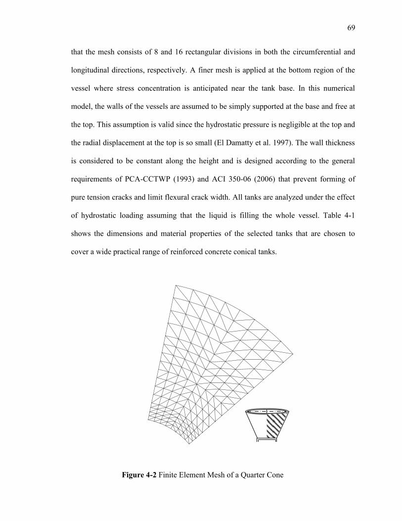
69
that the mesh consists of 8 and 16 rectangular divisions in both the circumferential and
longitudinal directions, respectively. A finer mesh is applied at the bottom region of the
vessel where stress concentration is anticipated near the tank base. In this numerical
model, the walls of the vessels are assumed to be simply supported at the base and free at
the top. This assumption is valid since the hydrostatic pressure is negligible at the top and
the radial displacement at the top is so small (El Damatty et al. 1997). The wall thickness
is considered to be constant along the height and is designed according to the general
requirements of PCA-CCTWP (1993) and ACI 350-06 (2006) that prevent forming of
pure tension cracks and limit flexural crack width. All tanks are analyzed under the effect
of hydrostatic loading assuming that the liquid is filling the whole vessel. Table 4-1
shows the dimensions and material properties of the selected tanks that are chosen to
cover a wide practical range of reinforced concrete conical tanks.
Figure 4-2 Finite Element Mesh of a Quarter Cone
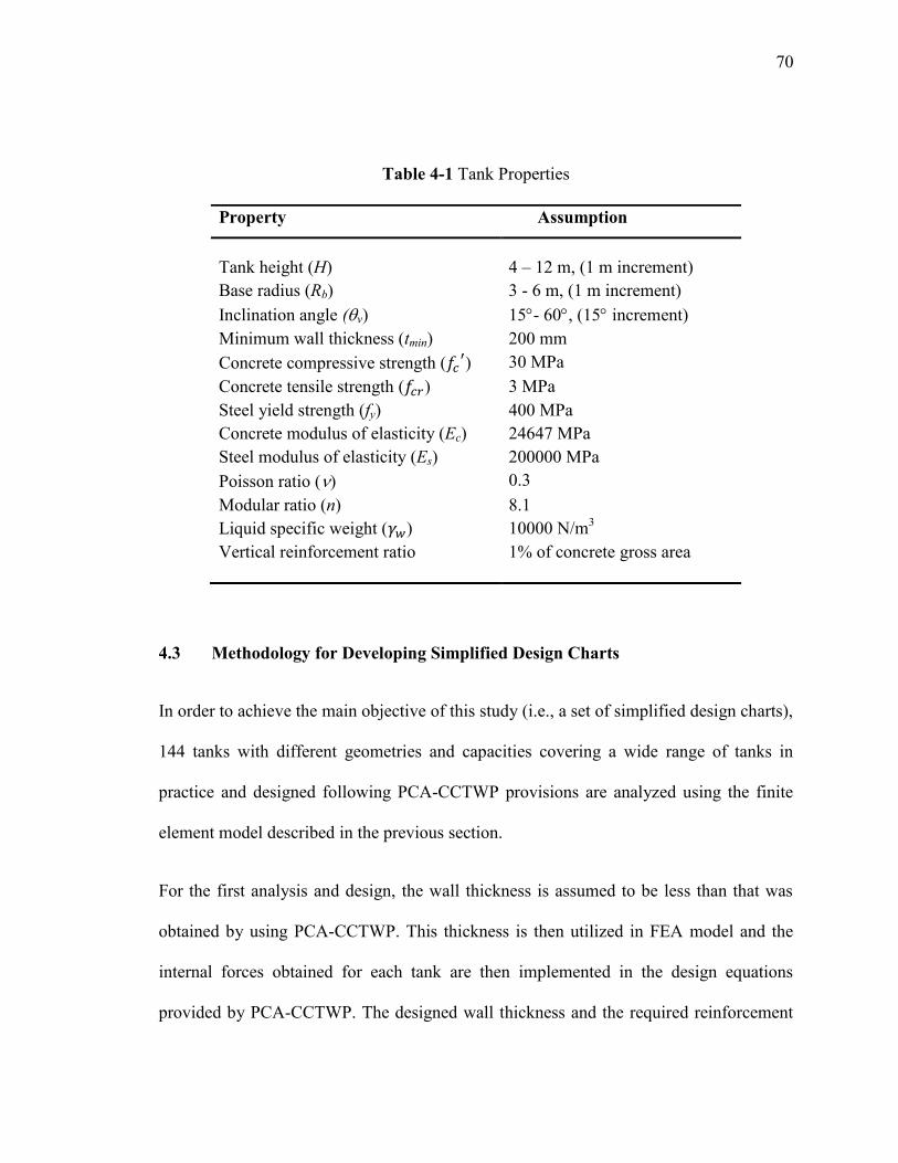
71
Table 4-1 Tank Properties
4.3 Methodology for Developing Simplified Design Charts
In order to achieve the main objective of this study (i.e., a set of simplified design charts),
144 tanks with different geometries and capacities covering a wide range of tanks in
practice and designed following PCA-CCTWP provisions are analyzed using the finite
element model described in the previous section.
For the first analysis and design, the wall thickness is assumed to be less than that was
obtained by using PCA-CCTWP. This thickness is then utilized in FEA model and the
internal forces obtained for each tank are then implemented in the design equations
provided by PCA-CCTWP. The designed wall thickness and the required reinforcement
Property Assumption
Tank height (H) 4 – 12 m, (1 m increment)
Base radius (Rb) 3 - 6 m, (1 m increment)
Inclination angle (v) 15- 60, (15 increment)
Minimum wall thickness (tmin) 200 mm
Concrete compressive strength ( ) 30 MPa
Concrete tensile strength ( ) 3 MPa
Steel yield strength (fy) 400 MPa
Concrete modulus of elasticity (Ec) 24647 MPa
Steel modulus of elasticity (Es) 200000 MPa
Poisson ratio () 0.3
Modular ratio (n) 8.1
Liquid specific weight ( ) 10000 N/m3
Vertical reinforcement ratio 1% of concrete gross area
71
in both the circumferential and longitudinal directions are achieved by repeating this
procedure.
Following the above approach, all chosen tanks are designed to satisfy both serviceability
and ultimate strength requirements. A minimum thickness for each tank is predicted to
satisfy both requirements and to achieve minimum weight of the vessel. It should be
mentioned that ACI350-06 and PCA-CCTWP provide a minimum thickness of 300 mm
for walls equal to or higher than 3 m to satisfy the constructability aspects. However,
other standards (e.g. BS2007 and EN 1992-3), do not provide a specific minimum wall
thickness and it is left for the designer and constructability requirements. In the current
study, a theoretical minimum thickness of 200 mm for the tanks’ walls is assumed
following the provisions of standards that do not provide restrictions on the minimum
wall thickness. This assumption is considered such that the simplified design charts
provide the designer with an optimum thickness that satisfies serviceability and strength
requirements only without taking into account the constructability aspects. The minimum
thickness that will be predicted from these design charts could be increased to satisfy
constructability requirements according to the designer judgment which might differ
based on the techniques used in construction.
The following steps summarize the methodology for developing the proposed design
charts.
4.3.1 Step 1: Design for the Minimum Wall Thickness
The main conclusion drawn from chapter 3 is that the PCA-CCTWP provisions combined
with the equivalent cylinder approach leads to an overdesigned thickness of the tanks’
72
walls. The reason behind this inaccurate design is that the hoop tension predicted by the
PCA-CCTWP approach is much higher than that obtained from the finite element
analysis. This discrepancy is related to the approximation in the equivalent cylinder
approach used to transfer the conical tank to an equivalent cylinder. As such, the
designed wall thickness following PCA-CCTWP provisions combined with the
equivalent cylinder approach can be reduced without affecting the serviceability
requirements.
Inordertoreachthereducedthickness(i.e.,optimumthickness),thewall’sthicknessis
first assumed to be less than that obtained in the first step by PCA-CCTWP. The reduced
thickness is then utilized in the FEA model to predict the internal forces. The tensile
capacity of the wall section is checked by Equation 4.1 to satisfy the cracking criteria.
This step is repeated many times for each tank until the applied tensile stresses equals to
the concrete tensile strength (i.e., ).
(
(4.1)
Where is the applied tensile strength, is concrete compressive strength, is the
shrinkage coefficient (i.e., , is the modulus of elasticity of horizontal
reinforced steel, is area of concrete for 1000 mm height section (i.e.,
, is the wall thickness, is the modular ratio (i.e.,
), and is the concrete
modulus of elasticity. is the area of horizontal reinforcement per 1000 mm height
section, and can be estimate from Equation 4.2, is the non factored ring hoop force per
1000 mm length resulting from the hydrostatic pressure,
73
(4.2)
Where is the maximum factored hoop tension , where is the
service hoop tension, is the steel yielding strength, and Sd is the environmental
durability factor that can be calculated from Equation 4.3.
(4.3)
Where is the strength reduction factor, ( for both hoop tension and flexural
members), is the steel yield strength, is the allowable stress in normal
environment, and
, in case of hydrostatic pressure and dead
loads.
In order to assess the applicability of the proposed methodology, the tanks that were
designed in chapter 3 following PCA-CCTWP approach are analyzed using the finite
element model. This is followed by redesigning these tanks by implementing the internal
forces obtained from the finite element analysis in PCA-CCTWP equations to predict the
wall thickness. It is noticed that the designed thicknesses, which comply with the
requirements of ACI350-06, are decreased significantly. Table 4-2 shows a comparison
between the walls` thicknesses designed by the FEA and those by the PCA-CCTWP as
previously presented in chapter 3. It is observed from this comparison that the optimum
design can lead to a reduction in the wall thicknesses ranging from 43% to 57% which
leads to a reduction in the cost of the construction material.
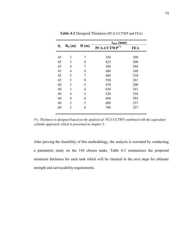
74
Table 4-2 Designed Thickness (PCA-CCTWP and FEA)
(*): Thickness is designed based on the analysis of PCA-CCTWP combined with the equivalent
cylinder approach, which is presented in chapter 3.
After proving the feasibility of this methodology, the analysis is extended by conducting
a parametric study on the 144 chosen tanks. Table 4-3 summarizes the proposed
minimum thickness for each tank which will be checked in the next steps for ultimate
strength and serviceability requirements.
v Rb (m) H (m) tmin (mm)
PCA-CCTWP(*)
FEA
45 3 7 350 200
45 3 8 425 200
45 4 7 380 204
45 4 8 480 240
45 5 7 480 238
45 5 8 550 281
60 3 5 470 200
60 3 6 630 241
60 4 5 520 250
60 4 6 660 285
60 5 5 600 257
60 5 6 700 327
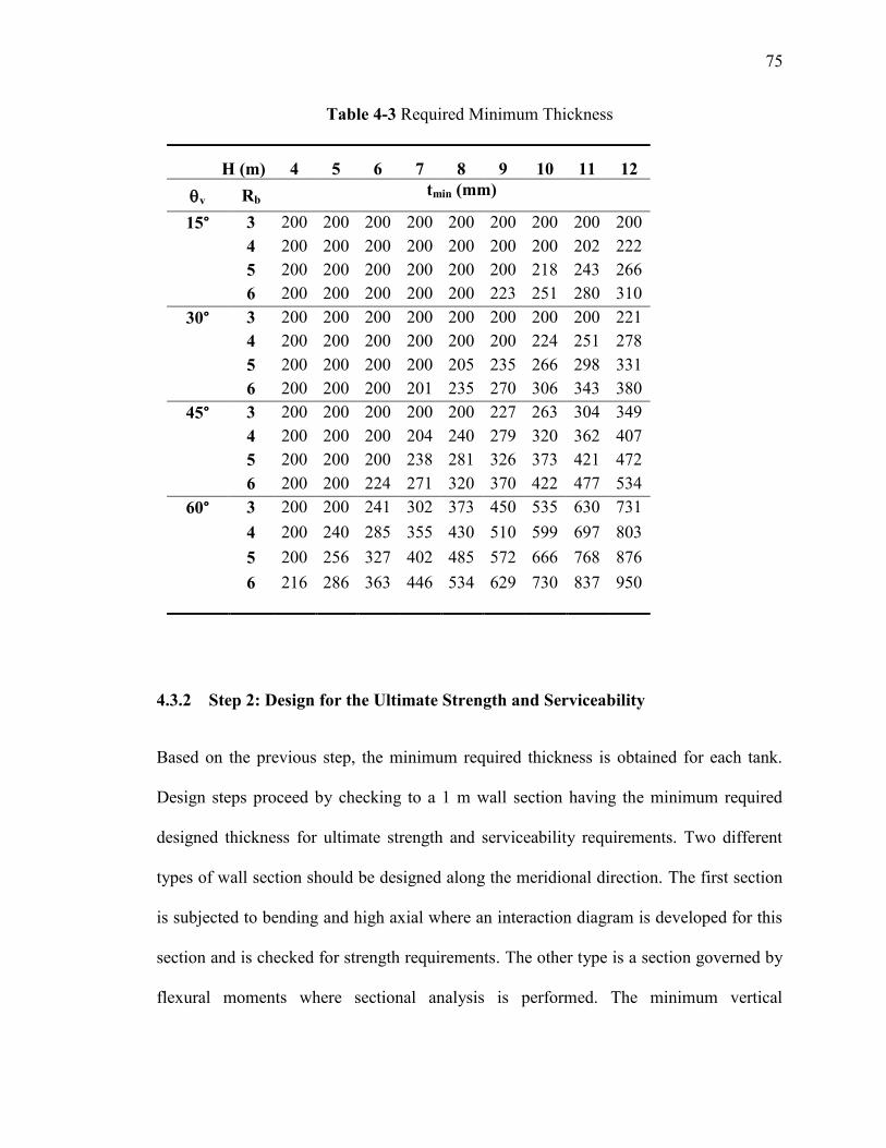
75
Table 4-3 Required Minimum Thickness
H (m) 4 5 6 7 8 9 10 11 12
v Rb tmin (mm)
15° 3 200 200 200 200 200 200 200 200 200
4 200 200 200 200 200 200 200 202 222
5 200 200 200 200 200 200 218 243 266
6 200 200 200 200 200 223 251 280 310
30° 3 200 200 200 200 200 200 200 200 221
4 200 200 200 200 200 200 224 251 278
5 200 200 200 200 205 235 266 298 331
6 200 200 200 201 235 270 306 343 380
45° 3 200 200 200 200 200 227 263 304 349
4 200 200 200 204 240 279 320 362 407
5 200 200 200 238 281 326 373 421 472
6 200 200 224 271 320 370 422 477 534
60° 3 200 200 241 302 373 450 535 630 731
4 200 240 285 355 430 510 599 697 803
5 200 256 327 402 485 572 666 768 876
6 216 286 363 446 534 629 730 837 950
4.3.2 Step 2: Design for the Ultimate Strength and Serviceability
Based on the previous step, the minimum required thickness is obtained for each tank.
Design steps proceed by checking to a 1 m wall section having the minimum required
designed thickness for ultimate strength and serviceability requirements. Two different
types of wall section should be designed along the meridional direction. The first section
is subjected to bending and high axial where an interaction diagram is developed for this
section and is checked for strength requirements. The other type is a section governed by
flexural moments where sectional analysis is performed. The minimum vertical
76
reinforcement is assumed to be (1% Ag) and is layered into two layers (0.5 % for each
face).
The previous mentioned steps are repeated for all selected tanks, leading to a
comprehensive data that are employed to develop the required design charts. These charts
provide a simple approach to adequately estimate the minimum required thickness and
the associated state of stresses that varies according to the tank’s geometry (i.e., tank
height H, base radius Rb, and angle of inclination v). It should be mentioned that the
proposed design charts are limited to the chosen range for each geometric parameter.
4.4 Simplified Design Charts
Based on the obtained data, two sets of charts are developed. The first one provides the
minimum required thickness associated with specific tank geometry. The charts are
arranged for each inclination angle and depend on both the tank height and its base
radius. The second set enables the designer to predict the maximum internal forces
developed in the tank’swall.Themaximum internal forces are illustrated according to
the inclination angle. For each angle, the internal forces are evaluated according to the
tank base radius and the ratio of tank height to wall thickness as will be explained in the
next sub-sections.
4.4.1 Minimum wall thickness determination
Using the charts provided in Figures 4-3, 4-4, 4-5, and 4-6, the minimum required wall
thickness is determined for each specific tank. These charts are categorized according to
inclination angles of (v = 15°, 30°, 45°, and 60°). For each specific angle of inclination,
the design chart gives different values of the required thickness according to the tank
77
height as well as the base radius. As an example, the required thickness for a conical tank
that have ( v = 30°, H = 9 m, and Rb = 6 m ) is 270 mm. it is important to note that this
study limits the minimum thickness to 200 mm. By observing the design charts for wall
thicknesses, it is noticed that the design charts are almost linear. This is expected since
this study deals with a non-cracked section and performs a linear analysis. The minimum
thickness of 200 mm satisfies the design requirements for most of the tanks having
inclination angle of 15° and height less than 9 m. it also is the designed thickness for
angles of 30 and 45, and a height less than 6 m. It is noticed that increasing the
inclination angle from 15° to 60° increased the required wall thickness about 10% to
320% depending on tank dimensions. The design charts also show that as the wall height
is increased from 3 m to 12 m, the ratio of increasing wall thickness ranges from 3% to
57%.
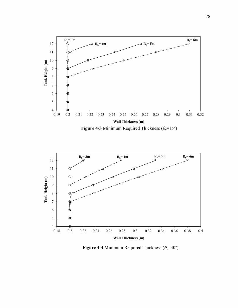
78
4
5
6
7
8
9
10
11
12
0.19 0.2 0.21 0.22 0.23 0.24 0.25 0.26 0.27 0.28 0.29 0.3 0.31 0.32
Tan
k H
eigh
t (m
)
Wall Thickness (m)
Rb= 3mRb= 4m Rb= 5m
Rb= 6m
4
5
6
7
8
9
10
11
12
0.18 0.2 0.22 0.24 0.26 0.28 0.3 0.32 0.34 0.36 0.38 0.4
Tan
k H
eigh
t (m
)
Wall Thickness (m)
Rb= 3m Rb= 4m Rb= 5m Rb= 6m
Figure 4-4 Minimum Required Thickness (v=30°)
Figure 4-3 Minimum Required Thickness (v=15°)
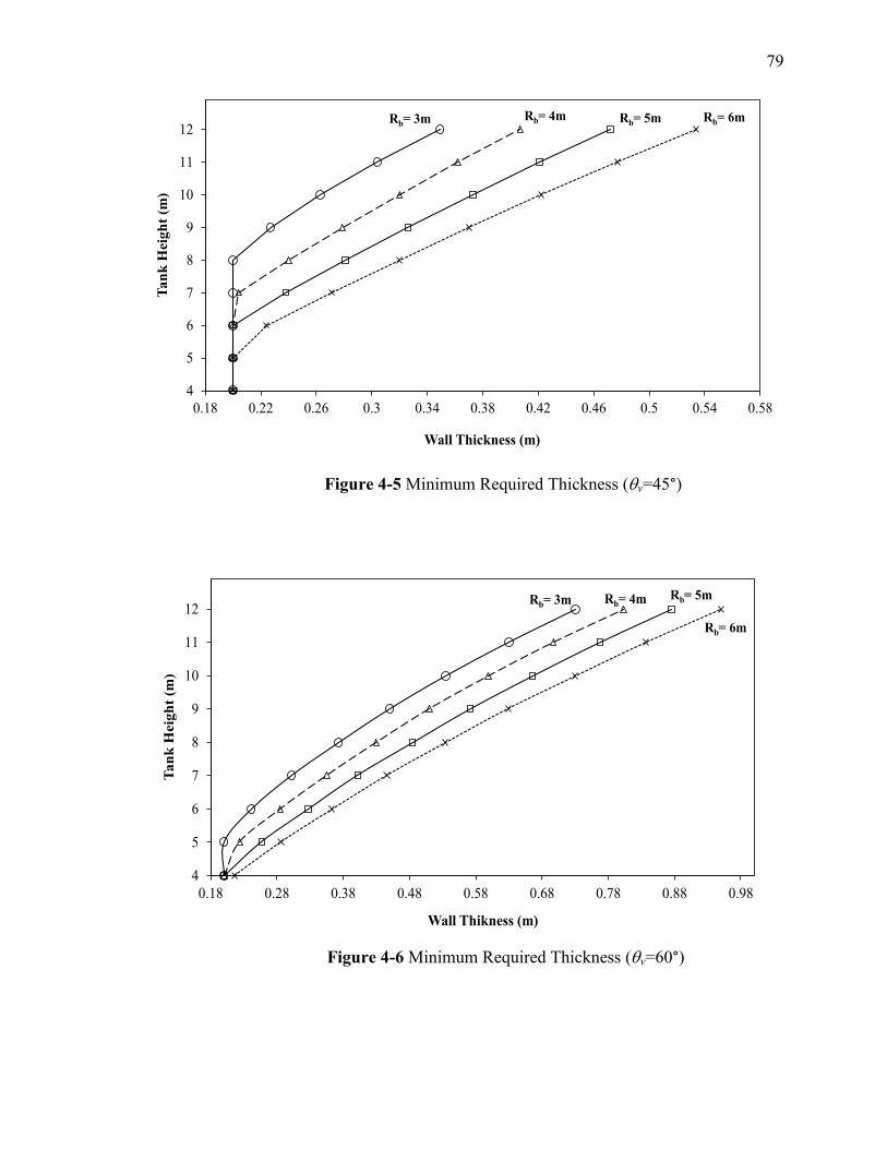
79
4
5
6
7
8
9
10
11
12
0.18 0.22 0.26 0.3 0.34 0.38 0.42 0.46 0.5 0.54 0.58
Tan
k H
eig
ht
(m)
Wall Thickness (m)
Rb= 3m Rb= 4m Rb= 5m Rb= 6m
4
5
6
7
8
9
10
11
12
0.18 0.28 0.38 0.48 0.58 0.68 0.78 0.88 0.98
Ta
nk
Heig
ht
(m)
Wall Thikness (m)
Rb= 3m Rb= 4m Rb= 5m
Rb= 6m
Figure 4-5 Minimum Required Thickness (v=45°)
Figure 4-6 Minimum Required Thickness (v=60°)
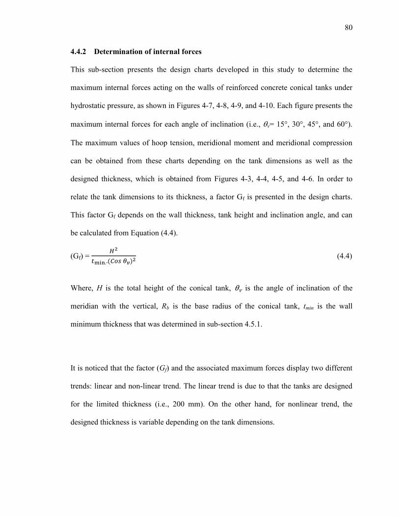
81
4.4.2 Determination of internal forces
This sub-section presents the design charts developed in this study to determine the
maximum internal forces acting on the walls of reinforced concrete conical tanks under
hydrostatic pressure, as shown in Figures 4-7, 4-8, 4-9, and 4-10. Each figure presents the
maximum internal forces for each angle of inclination (i.e., v= 15°, 30°, 45°, and 60°).
The maximum values of hoop tension, meridional moment and meridional compression
can be obtained from these charts depending on the tank dimensions as well as the
designed thickness, which is obtained from Figures 4-3, 4-4, 4-5, and 4-6. In order to
relate the tank dimensions to its thickness, a factor Gf is presented in the design charts.
This factor Gf depends on the wall thickness, tank height and inclination angle, and can
be calculated from Equation (4.4).
(Gf) =
( (4.4)
Where, H is the total height of the conical tank, is the angle of inclination of the
meridian with the vertical, Rb is the base radius of the conical tank, tmin is the wall
minimum thickness that was determined in sub-section 4.5.1.
It is noticed that the factor (Gf) and the associated maximum forces display two different
trends: linear and non-linear trend. The linear trend is due to that the tanks are designed
for the limited thickness (i.e., 200 mm). On the other hand, for nonlinear trend, the
designed thickness is variable depending on the tank dimensions.
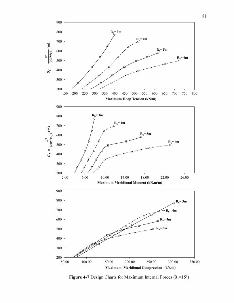
81
Figure 4-7Design Charts for Maximum Internal Forces (v=15°)
Figure 4-7 Design Charts for Maximum Internal Forces (v=15°)
200
300
400
500
600
700
800
900
150 200 250 300 350 400 450 500 550 600 650 700 750 800
H2/(
Co
s
v)2
. t
(m)
Maximum Hoop Tension (kN/m)
Rb= 3m
Rb= 4m
Rb= 5m
Rb= 6m
200
300
400
500
600
700
800
900
2.00 6.00 10.00 14.00 18.00 22.00 26.00
H2/(
Cos
v)2
. t
(m)
Maximum Meridional Moment (kN.m/m)
Rb= 3m
Rb= 4m
Rb= 5m
Rb= 6m
200
300
400
500
600
700
800
900
50.00 100.00 150.00 200.00 250.00 300.00 350.00
H2/(
Cos
v)2
. t
(m)
Maximum Meridional Compressiont (kN/m)
Rb= 3m
Rb= 4m
Rb= 5m
Rb= 6m
( ) (
m)
( ) (
m)
( )
( m )
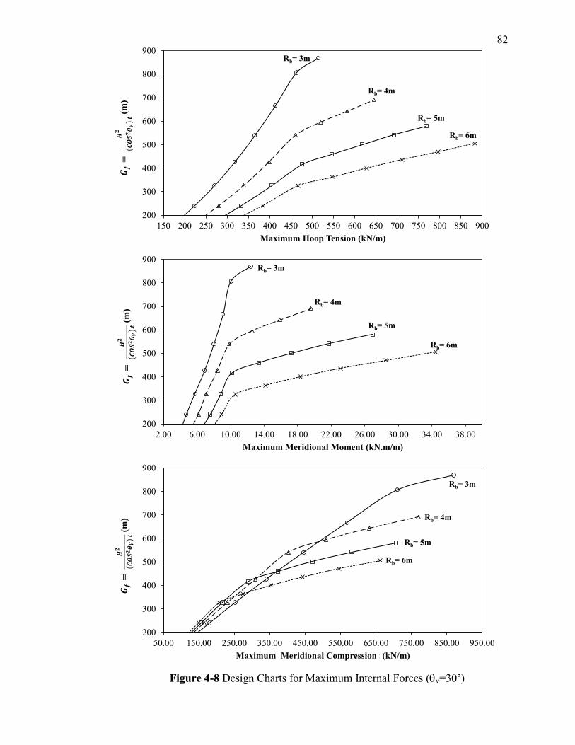
82
Figure 4-8 Design Charts for Maximum Internal Forces (v=30°)
200
300
400
500
600
700
800
900
150 200 250 300 350 400 450 500 550 600 650 700 750 800 850 900
H2/(
Cos
v)2
. t
(m)
Maximum Hoop Tension (kN/m)
Rb= 3m
Rb= 4m
Rb= 5m
Rb= 6m
200
300
400
500
600
700
800
900
2.00 6.00 10.00 14.00 18.00 22.00 26.00 30.00 34.00 38.00
H2/(
Cos
v)2
. t
(m)
Maximum Meridional Moment (kN.m/m)
Rb= 3m
Rb= 4m
Rb= 5m
Rb= 6m
200
300
400
500
600
700
800
900
50.00 150.00 250.00 350.00 450.00 550.00 650.00 750.00 850.00 950.00
H2/(
Cos
v)2
. t
(m)
Maximum Meridional Compressiont (kN/m)
Rb= 3m
Rb= 4m
Rb= 5m
Rb= 6m
( ) (
m)
( ) (
m)
( ) (
m)
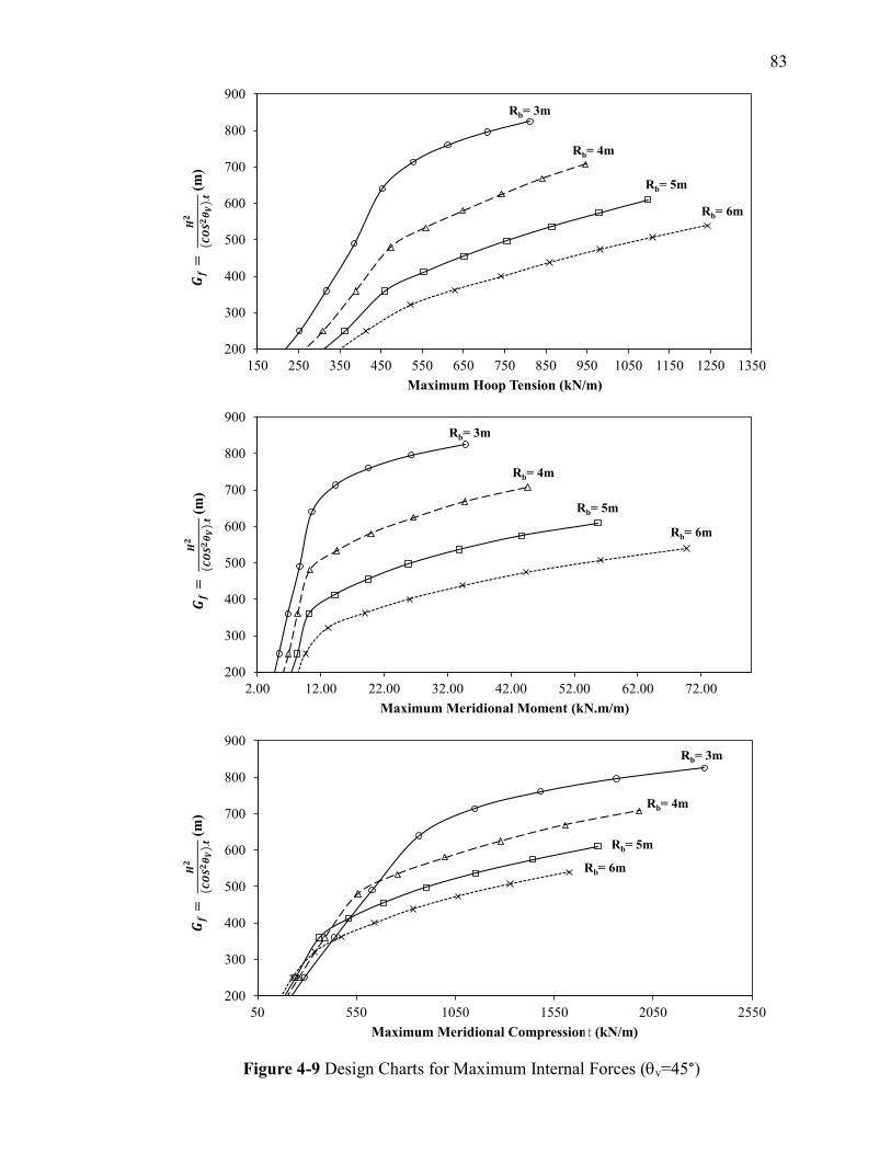
83
Figure 4-9 Design Charts for Maximum Internal Forces (v=45°)
200
300
400
500
600
700
800
900
150 250 350 450 550 650 750 850 950 1050 1150 1250 1350
H2/(
Cos
v)2
. t
(m)
Maximum Hoop Tension (kN/m)
Rb= 3m
Rb= 4m
Rb= 5m
Rb= 6m
200
300
400
500
600
700
800
900
2.00 12.00 22.00 32.00 42.00 52.00 62.00 72.00
H2/(
Cos
v)2
. t
(m)
Maximum Meridional Moment (kN.m/m)
Rb= 3m
Rb= 4m
Rb= 5m
Rb= 6m
200
300
400
500
600
700
800
900
50 550 1050 1550 2050 2550
H2/(
Cos
v)2
. t
(m)
Maximum Meridional Compressiont (kN/m)
Rb= 3m
Rb= 4m
Rb= 5m
Rb= 6m
( ) (
m)
( ) (
m)
( ) (
m)
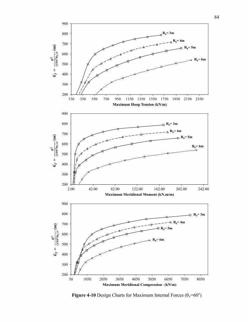
84
Figure 4-10 Design Charts for Maximum Internal Forces (v=60°)
200
300
400
500
600
700
800
900
150 350 550 750 950 1150 1350 1550 1750 1950 2150 2350
H2/(
Co
s
v)2
. t
(m)
Maximum Hoop Tension (kN/m)
Rb= 3m
Rb= 4m
Rb= 5m
Rb= 6m
200
300
400
500
600
700
800
900
2.00 42.00 82.00 122.00 162.00 202.00 242.00
H2/(
Co
s
v)2
. t
(m)
Maximum Meridional Moment (kN.m/m)
Rb= 3m
Rb= 4m
Rb= 5m
Rb= 6m
200
300
400
500
600
700
800
900
50 1050 2050 3050 4050 5050 6050 7050 8050
H2/(
Co
s
v)2
. t
(m)
Maximum Meridional Compressiont (kN/m)
Rb= 3m
Rb= 4m
Rb= 5m
Rb= 6m
( ) (
m)
( ) (
m)
( ) (
m)
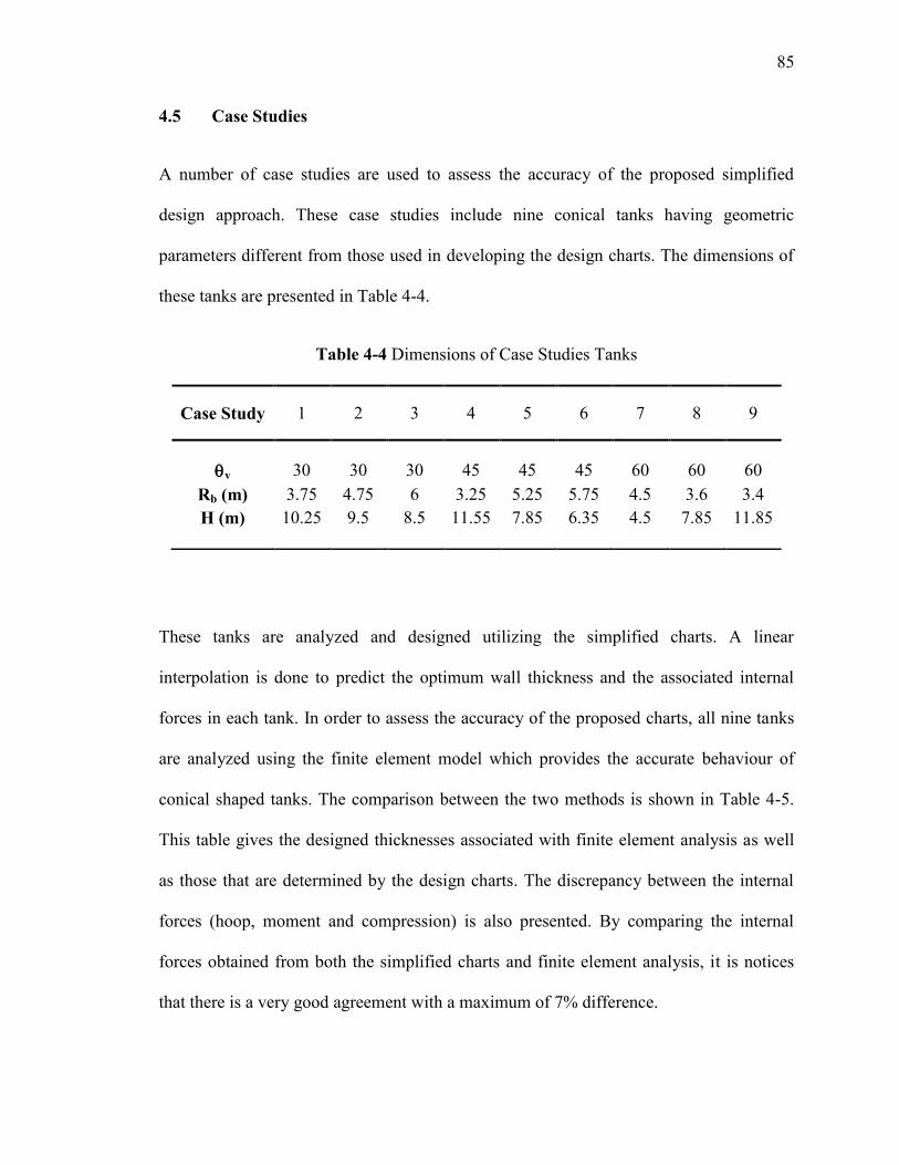
85
4.5 Case Studies
A number of case studies are used to assess the accuracy of the proposed simplified
design approach. These case studies include nine conical tanks having geometric
parameters different from those used in developing the design charts. The dimensions of
these tanks are presented in Table 4-4.
Table 4-4 Dimensions of Case Studies Tanks
These tanks are analyzed and designed utilizing the simplified charts. A linear
interpolation is done to predict the optimum wall thickness and the associated internal
forces in each tank. In order to assess the accuracy of the proposed charts, all nine tanks
are analyzed using the finite element model which provides the accurate behaviour of
conical shaped tanks. The comparison between the two methods is shown in Table 4-5.
This table gives the designed thicknesses associated with finite element analysis as well
as those that are determined by the design charts. The discrepancy between the internal
forces (hoop, moment and compression) is also presented. By comparing the internal
forces obtained from both the simplified charts and finite element analysis, it is notices
that there is a very good agreement with a maximum of 7% difference.
Case Study 1 2 3 4 5 6 7 8 9
v 30 30 30 45 45 45 60 60 60
Rb (m) 3.75 4.75 6 3.25 5.25 5.75 4.5 3.6 3.4
H (m) 10.25 9.5 8.5 11.55 7.85 6.35 4.5 7.85 11.85
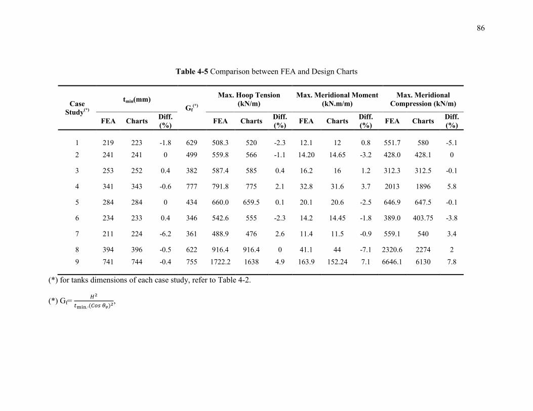
86
Table 4-5 Comparison between FEA and Design Charts
Case
Study(*)
tmin(mm)
Gf(*)
Max. Hoop Tension
(kN/m)
Max. Meridional Moment
(kN.m/m)
Max. Meridional
Compression (kN/m)
FEA Charts Diff.
(%) FEA Charts
Diff.
(%) FEA Charts
Diff.
(%) FEA Charts
Diff.
(%)
1 219 223 -1.8 629 508.3 520 -2.3 12.1 12 0.8 551.7 580 -5.1
2 241 241 0 499 559.8 566 -1.1 14.20 14.65 -3.2 428.0 428.1 0
3 253 252 0.4 382 587.4 585 0.4 16.2 16 1.2 312.3 312.5 -0.1
4 341 343 -0.6 777 791.8 775 2.1 32.8 31.6 3.7 2013 1896 5.8
5 284 284 0 434 660.0 659.5 0.1 20.1 20.6 -2.5 646.9 647.5 -0.1
6 234 233 0.4 346 542.6 555 -2.3 14.2 14.45 -1.8 389.0 403.75 -3.8
7 211 224 -6.2 361 488.9 476 2.6 11.4 11.5 -0.9 559.1 540 3.4
8 394 396 -0.5 622 916.4 916.4 0 41.1 44 -7.1 2320.6 2274 2
9 741 744 -0.4 755 1722.2 1638 4.9 163.9 152.24 7.1 6646.1 6130 7.8
(*) for tanks dimensions of each case study, refer to Table 4-2.
(*) Gf=
( ,
87
4.5.1 Numerical Example
For more illustration, the general procedure used to design tank No. 5 is presented as an
example in the following steps. These steps are considered as a typical procedure that can
be repeated to analyze and design any conical tank with geometry lying within the range
specified in this study.
- Tank dimensions (v = 30°, H = 6 m, Rb = 8.5 m)
- In order to determine the minimum required thickness, Figure 4-4 is used for v =
30°, and height H = 6 m. Wall thicknesses for base radiuses Rb = 8 m, and Rb = 9
m are determined. A linear interpolation is then used to determine the required
thickness of Rb = 8.5 m. (tmin = 252 mm).
- Calculate the factor Gf =
( =
( = 382 m.
- Figure 4-8 is used for v = 30°, where the internal forces corresponding to factors
Gf = 300 m and Gf = 400 m are obtained. A linear interpolation is applied to
determine the maximum internal forces for Gf = 382 m (Hoop = 520 kN/m,
Moment = 12 kN.m/m, Compression = 580 kN/m).
4.6 Conclusions
The current study presents a simplified procedure to analyze and design reinforced
concrete conical tanks under the effect of hydrostatic pressure. This procedure depends
on different design charts that are categorised according to the tank dimensions. The
required wall thickness and the associated maximum internal forces (hoop, moment and
88
compression) can be determined by using the proposed charts. In order to develop these
design charts, a wide range of conical tanks having various dimensions is analyzed and
designed by using a linear finite element analysis method. The design is repeated for each
tank until the minimum required thickness is achieved. The serviceability and strength
requirements of both ACI350-06 and PCA-CCTWP are satisfied in the design. The
accuracy of the developed charts is validated by a number of numerical case studies. The
following main conclusion can be drawn from the current study.
The design charts provided in this study enable the designers to determine the
minimum required thicknessfortanks’walls.Thisthicknesssatisfiesserviceability
and strength requirements, leading to a reduction in the vessel own weight as well
as the construction cost.
It is noticed that all tanks having walls inclined with an angle 15° to the vertical
axis are governed by a minimum thickness of 200 mm. Also, this thickness (i.e.,
200 mm) satisfies the design requirements of all conical tanks with height ranges
from 4 m to 5 m regardless the variation in other geometric parameters. On the
other hand, significant increase in the required thickness is noticed for tanks higher
than 7 m height.
The design charts provide simple and accurate procedure to determine the
maximum internal forces (hoop, meridional moment and meridional compression).
The proposed charts are presented graphically according to the angle of inclination
and the base radius. For each specific angle of inclination and base radius, the
predicted maximum internal forces are provided according to the ratio between the
tank height and the minimum designed thickness. The obtained forces can be
89
successfully utilized to design the wall section for ultimate strength design
requirements and the related reinforcements.
91
5 CHAPTER 5
COST ANALYSIS OF CONICAL TANKS;
COMPARISON BETWEEN REINFORCED CONCRETE AND STEEL
5.1 Introduction
The vessels used for liquid storage containers are commonly built in a conical shape,
including pure conical tanks and conical cylindrical combined tanks. The construction of
conical tanks is dominated by using either steel, conventional reinforced concrete or
partially pre-stressed concrete. The decision to select the most proper construction
material for such tanks depends on various factors: structural performance, material cost,
life service, material availability and cost of labour works (Barry 2011).
The main advantages of reinforced concrete tanks over steel tanks are that they provide
high resistance to compression stresses and have long service life (i.e., up to 50 years)
compared to steel tanks (i.e., up to 20 years) (Cheremisinoff 1996). On the other hand,
the main disadvantages of reinforced concrete tanks are related to the low tensile strength
and the large thickness required to satisfy design requirements which leads to a
significant increase in the own weight. Despite the advantage of using reinforced
concrete as a construction material for storage tanks, steel tanks are widely used in
Canada and USA over the last 25 years. This is due to the fact that steel storage tanks are
leak-free structures and they also provide high tension resistance and lighter own weight
compared to reinforced concrete counterparts. The only concern about steel as a
construction material is that it is sensitive to geometric imperfections, buckling, and
corrosion problems. Most of structural optimization techniques of conical tanks deal with
91
minimizing the weight of the structure by achieving the minimum thickness which
satisfies design requirements. (Kamal, 1998; El Ansary et al. 2010, 2011).
Choosing the most proper construction material which leads to an economical design is
not an easy task as it involves many parameters. These parameters are: type of the
structure, construction techniques, and life-cycle cost of construction material. The
literature shows that very few studies are concerned about comparing the cost of
reinforced concrete conical tanks to that of steel counterparts.
In this regard, few researches presented trials to minimize the cost of storage tanks;
Saxena et al. (1987) presented a cost function which includes the cost of different
construction materials (e.g. concrete and steel) and the cost of formwork. It was
concluded in their study that mores savings in cost can be achieved for water tanks
having large storage capacities. Later, Copley et al. (2002) presented the design and cost
analysis of a partially pre-stressed concrete conical tank having a storage capacity of 2
Million Gallons. In their cost analysis, they showed that the cost of construction of a steel
tank is more economical than a pre-stressed concrete counterpart. However, the life-cycle
cost analysis, which was implemented in Copley`s work, showed that pre-stressed
concrete is a better alternative in terms of long service life.
Barakat and Altoubat (2009) introduced optimization techniques which were coupled
with the finite element method in the analysis and design of reinforced concrete conical
and cylindrical water tanks. They illustrated the effect of different parameters, which
include the wall thickness at the base and at the top of the tank, the base thickness, the
tank height, the inclination angle, and concrete compressive strength, on the optimum
design. Barakat and Altoubat (2009) concluded that the total cost of cylindrical tanks is
92
more than that of conical water tanks having the same volume. This increase in cost has
been estimated by 20% to 30% and by 18% to 40% when working stress design method
and ultimate strength design method were used, respectively.
The main objective of this chapter is to investigate the economics of reinforced concrete
conical tanks versus steel counterparts. This study considers only conical vessels having a
constant thickness and subjected to hydrostatic loading. The design of concrete tanks is
conducted following the simplified approach presented in the previous chapter, which
complies with the requirements of the ACI350-06. On the other hand, the design of steel
tanks is obtained by using the simplified approach provided by Sweedan and El Damatty
(2009).
According to the American Public Works Association, it is essential to include the life-
cycle costing procedures in the project bidding (Ross, 2001). As such, this research
includes an estimation of a 50 years life-cycle cost for both concrete and steel tanks in
addition to the construction cost (i.e., construction material and labour works). The same
service life of 50 years is selected for both reinforced concrete conical tanks and steel
tanks for the purpose of comparison between the two options.
Moreover, this study presents an average unit prices for contractors working in Canada. It
should be noted that these unit prices are variable depending on various factors such as
site location, material availability, energy cost and others. A total of 52 tanks are chosen
to cover a wide range of practical tank dimensions and are categorized into three
capacities; 500 m3, 1750 m
3, and 3000 m
3. These tanks are designed first as reinforced
concrete tanks then as steel tanks. The cost of each tank is estimated and a comparison is
then conducted to analyze the economics of using the two construction materials (i.e.,
93
reinforced concrete and steel) for these tanks. Statistical analyses are also performed in
order to evaluate the factors having the most significant effect on the cost of conical
tanks.
5.2 Design of Reinforced Concrete Conical Tanks under Hydrostatic Load
Design of reinforced concrete conical tanks includes many parameters; angle of
inclinationoftank’swall,tankheight,baseradius,andwallthickness.Inorder to achieve
an adequate design, it is essential to predict the maximum internal forces that include
hoop tension acting in the circumferential direction and the meridional moment combined
with the axial compression force acting in the longitudinal direction. Conducting this
analysis needs modeling experience and knowledge about design steps. An alternative
way is to rely on simplified design procedures which satisfy code provisions. In this
study, a reliable simplified procedure proposed in the previous chapter was utilized in the
design of reinforced concrete tanks. This approach includes certain design charts that
were developed by modelling a wide practical range of conical tanks having different
dimensions. All analyzed tanks were modelled using a degenerated consistent sub-
parametric shell element developed in-house (Koziey and Mirza 1997; El Damatty et al.
1997, 1998).
The simplified design charts enable the designers to easily evaluate the required
minimum thickness and the associated internal forces in both circumferential and
longitudinal directions. Consequently, the cost of the required construction material can
be estimated.
The steps of the procedure involved in the design can be explained as follows:
94
1. The tank dimensions (angle of inclination v, base radius Rb, and tank height H)
are chosen according to the required tank volume (i.e., capacity). It should be
mentioned that specific capacity ranges are assumed in this study covering a
practical range starting from 500 m3 up to 3000 m
3.
2. Figures 4-5, 4-6, 4-7, or 4-8, which were presented in chapter 4, are then used to
determine the minimum required thickness. By knowing the values of the base
radius and the tank height, linear interpolation is applied to predict the minimum
required thickness.
3. A factor (Gf), which relates the tank dimensions to the internal forces that are
developed in the tank wall due to hydrostatic pressure, is calculated using
Equation 5.1. This factor is then used in the charts illustrated in Figures 4-9, 4-10,
4-11 or 4-12toestimatetheinternalforcesdevelopedintanks’wallsduetoun-
factored hydrostatic pressure. The outputs of these charts include hoop tension,
meridional moment and meridional compression.
(Gf) =
( (5.1)
4. The required circumferential (horizontal reinforcement) ( is then calculated
using Equation 5.2.
(5.2)
Where is the maximum factored hoop tension force magnified by the environmental
durability factor , ( , where is the service hoop tension obtained
from step 3, is the steel yielding strength, and Sd is the environmental durability factor
calculated from Equation 5.3.
95
(5.3)
In Equation 5.3, is the strength reduction factor, ( for both hoop tension and
flexural members), = 400 MPa is the steel yield strength, is the
allowable stress in normal environment, and
, in case of
hydrostatic pressure and dead loads.
5.3 Design of Steel Conical Tanks under Hydrostatic Load
Similar to reinforced concrete tanks, hydrostatic pressure acting on the walls of steel
tanks leads to tension hoop stresses (h) that are acting in the circumferential direction
and vary along the wall height. In addition, meridional compressive stresses (m) that
reach their maximum value at the base of the wall are acting in the meridional direction.
Those stresses are magnified due to the effect of boundary conditions as well as
geometric imperfections. As such, a magnification factor should be provided to relate the
theoretical membrane stresses, which can be evaluated from static equilibrium of the
shell to the actual maximum stresses acting on the wall. Sweedan and El Damatty (2009)
developed a simplified procedure that can evaluate this magnification factor associated
with the maximum stresses developed in the tank’s wall. Consequently, the wall
thickness can be designed to prevent steel yielding. This simplified procedure is utilized
in the current study to design the steel conical tanks under consideration according to the
following steps:
1. Thetanks’dimensions(angleofinclinationv, base radius Rb, and tank height H)
are chosen to be similar to the concrete tanks designed in section 5.2 to keep
96
storage capacities the same. For each tank, an initial value of the wall thickness
(ts) is assumed taking into account that the minimum thickness is 6.4 mm
according to AWWA-D100 (2005) code provisions.
2. From static equilibrium, the theoretical tensile hoop stress ( ) and the
theoretical meridional compression stress ( ) are calculated from Equations
5.4, and 5.5, respectively.
(5.4)
[ (
⁄ ] (5.5)
3. Based on the Von Mises yield criterion, the theoretical maximum effective
membrane stresses (lth
) is calculated from Equations (5.6 to 5.9)
√
[( ( ( ] (5.6)
in which
(5.7)
(5.8)
(5.9)
97
4. The magnification factor () is then calculated from Equation 5.10.
(
)
(
)
(
)
(
) (
(5.10)
Where, the regression factors (a, b, c, e, f, g, h) are given in Table B1 in Appendix
B. It should be mentioned that a good quality of welding of steel panels is
assumed in the current study. As such, regression factors for good conical shells are
used in Equation 5.10. A yield stress of 300 MPa is assumed for all studied tanks.
5. The total actual stress (l) is then calculated by multiplying the magnification
factor () by the theoretical maximum effective membrane stresses (lth
) as shown
in Equation (5.11).
(5.11)
6. The actual total stress is then compared to the yield strength of steel ( y = 300
MPa ). The yield strength should be greater than the actual total stress. The
procedure is repeated until the optimum thickness is achieved (i.e., ).
5.4 Cost Estimation
The total cost of the storage vessel of a tank is the summation of the cost of different
parameters. This study focuses on the construction costs, which includes material,
labours, and erection costs as well as the life-cycle cost. This section presents the details
and methodology of analyzing the cost of each tank using two different construction
materials (reinforced concrete and steel).
98
5.4.1 Construction Cost Estimation
In this sub-section, the cost of construction using each material (i.e., reinforced concrete,
and steel) is estimated to identify the most cost effective construction material for conical
tanks. The cost of reinforced concrete, which includes labour works, is measured by
concrete volume, the weight of steel rebar and the surface area of the formwork. For the
cost of steel tanks, the martial unit prices are presented by unit weight. The prices
assumed in the current study are based on average prices collected from the local
construction industry.
5.4.1.1 Construction Cost Estimation for Concrete Tanks
The cost of materials and construction is estimated according to the volume of
concrete and the reinforcing ratio of circumferential (i.e., horizontal) and
longitudinal (i.e., vertical) steel as well as the surface area for the formwork (EL
Reedy, 2011). Table 5-1 shows the unit prices for concrete used in the
construction of the tanks considered in this study. The construction cost function
is presented as the summation of the following parameters:
Costofconcrete=(tank’ssurfacearea×wallthickness)×costofcubicmeterof
concrete
Cost of reinforcement steel = concrete volume × 7.85
× ( sh + sv ) × cost of
steel
Where is the ratio of circumferential steel (
) As is the area of
circumferential reinforcement that is determined by using the simplified design
charts. Referring to Equation (5.2), the area of the circumferential reinforcement can
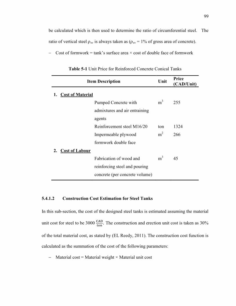
99
be calculated which is then used to determine the ratio of circumferential steel. The
ratio of vertical steel sv is always taken as (sv = 1% of gross area of concrete).
Cost of formwork=tank’ssurfacearea×costofdoublefaceofformwork
Table 5-1 Unit Price for Reinforced Concrete Conical Tanks
Item Description Unit Price
(CAD/Unit)
1. Cost of Material
Pumped Concrete with
admixtures and air entraining
agents
m3
255
Reinforcement steel M16/20 ton 1324
Impermeable plywood
formwork double face
m2 266
2. Cost of Labour
Fabrication of wood and
reinforcing steel and pouring
concrete (per concrete volume)
m3 45
5.4.1.2 Construction Cost Estimation for Steel Tanks
In this sub-section, the cost of the designed steel tanks is estimated assuming the material
unit cost for steel to be 3000
. The construction and erection unit cost is taken as 30%
of the total material cost, as stated by (EL Reedy, 2011). The construction cost function is
calculated as the summation of the cost of the following parameters:
Material cost = Material weight × Material unit cost
111
= (Steel unit weight; 7.850
) × wall thickness; ts) × (Tank
surface area) × (material unit cost; 3000
)
Total cost (material + Construction) per volume (
) = (
5.4.2 Life-Cycle Costs
In order to estimate the current cost of future maintenance and rehabilitation works, the
present value analysis method is performed for all concrete and steel tanks for a service
life of 50 years (EL Reedy, 2011). This method is widely used in construction
applications and it also presents the future costs in today’s monetary taking in
considerations the inflation and interest rates. It should be mentioned that for comparison
purposes, the same period of life-cycle (i.e., 50 years) is chosen for both steel and
concrete tanks. EL Reedy (2011) provided an expression to calculate the value of
maintenance and repairs required, as shown in Equation (5.12).
( ( (5.12)
Where; m is the discount rate (m = 4%), and n is the number of years of each
maintenance period.
Based on the data collected from the local market, the maintenance cost of concrete tanks
is assumed in the current study to be 89
every 5 years while in case of steel, it is
recommended to cost 40
at a period of 3 years. It is worth to mention that the
operating cost is not taken as part of this study.
111
5.5 Results and Discussion
This study includes 52 conical tanks having wide range of dimensions with different
capacities; 500 m3, 1750 m
3, and 3000 m
3. The dimensions of these tanks are presented in
Table 5-2. The considered tanks are first designed as reinforced concrete and then as steel
tanks according to the simplified design procedures mentioned in the previous sections.
The cost analysis is then conducted for all designed tanks as presented in Table 5-2. This
table shows the design outputs and the total cost described as price per unit volume (i.e.,
CAD per m3) for each tank.
The comparison between the cost of reinforced concrete conical tanks and steel tanks is
displayed in Figures 5-1, 5-2, and 5-3 for tanks with volumes of 500 m3, 1750 m
3,
3000 m3, respectively. Also, each figure categorizes the tank cost according to the base
radiuses, where Rb is varying from 3 m to 6 m with an increment of 0.5 m. Table 5-2 and
Figure 5-1 show that steel tanks are more cost-effective than reinforced concrete for
small capacity tanks, i.e., 500 m3
tanks. The average total cost of reinforced concrete
conical tanks are estimated to be 338
, which is approximately 1.7 times the cost of
steel counterparts.
For conical tanks having a volume of 1750 m3, it is concluded that steel tanks are more
economical than reinforced concrete tanks. Figure 5-2 shows that the total cost of steel
tanks is less than that of reinforced concrete tanks having the same dimensions. In
general, steel tanks show less cost compared to reinforced concrete counterparts with a
percentage of reduction varying between 4% and 39%. It can be noticed from the figure
that in only two cases the cost of steel tanks is found to be greater than that of reinforced
concrete tanks. The reported percentage of increase for these two cases are 9 % and 2 %
112
for tanks having walls inclined to the vertical with an angle of 60° and having base
radiuses of 3 m, and 3.5 m, respectively.
Based on the cost analysis of large capacity (3000 m3) tanks as presented in Figure 5-3, it
can be noticed that in some cases concrete as a construction material is a more
economical choice. Figure 5-3 shows that the cost of concrete tanks is less than steel for
the case of wide conical tanks having walls inclined to the vertical with an angle greater
than 45° and a base radius less than 4 m. Otherwise, steel provides a more economical
choice for all conical tanks having 30° inclination angle and tanks with 45° walls and
having a base radiuses of (4 m to 6 m). Based on the results reported for large capacity
tanks, no clear trend can be reached in order to decide which construction material is the
most cost effective one.
The results obtained from the cost analysis are evaluated statistically by using one way
analysis of variance ANOVA for a single factor (Stamatis 2002). This analysis is
conducted to assess the significance in the change of the cost from one case to another.
Two different case studies are performed using ANOVA. The first case is conducted for
reinforced concrete tanks and steel counterparts in order to study the variance in the cost
function with the change of material type. In the second case of this study, ANOVA is
employed to evaluate the effect of tank dimensions on its cost for each type of the studied
tanks.

113
Table 5-2 Design and Cost of Conical Tanks
(Capacity = 500 m3)
Tank # Rb
(m) v H (m)
Section Design Cost (CAD/m3)
Concrete Steel Concrete Steel
tc
(mm) sh
(%)ts (mm) Construction Life-Cycle Sum Construction Life-Cycle Sum
1 3 15 8.85 200 1.01 6.4 177 214 391 94 134 228
2 3 30 6.43 200 0.88 6.4 165 201 366 89 126 215
3 3 45 4.96 200 0.9 6.4 177 215 392 95 134 229
4 3.5 15 7.65 200 0.98 6.4 165 200 365 88 125 213
5 3.5 30 5.77 200 0.87 6.4 158 192 350 85 120 205
6 3.5 45 4.55 200 0.91 6.4 171 207 378 91 129 220
7 4 15 6.6 200 0.92 6.4 153 186 339 82 116 198
8 4 30 5.16 200 0.86 6.4 150 182 332 80 114 194
9 4 45 4.15 200 0.91 6.4 164 199 363 88 124 212
10 4.5 15 5.7 200 0.88 6.4 142 173 315 76 108 184
11 4.5 30 4.61 200 0.84 6.4 142 173 315 76 108 184
12 5 15 4.94 200 0.86 6.4 133 161 294 71 101 172
13 5.5 15 4.3 200 0.82 6.4 124 151 275 67 94 161
14 6 15 3.76 200 0.79 6.4 115 141 256 62 88 150
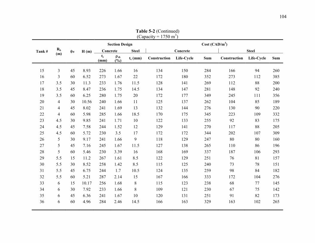
114
Table 5-2 (Continued)
(Capacity = 1750 m3)
Tank # Rb
(m) v H (m)
Section Design Cost (CAD/m3)
Concrete Steel Concrete Steel
tc
(mm) sh
(%)ts (mm) Construction Life-Cycle Sum Construction Life-Cycle Sum
15 3 45 8.93 226 1.66 16 134 150 284 166 94 260
16 3 60 6.52 273 1.67 22 172 180 352 273 112 385
17 3.5 30 11.3 233 1.76 11.5 128 141 269 112 88 200
18 3.5 45 8.47 236 1.75 14.5 134 147 281 148 92 240
19 3.5 60 6.25 280 1.75 20 172 177 349 245 111 356
20 4 30 10.56 240 1.66 11 125 137 262 104 85 189
21 4 45 8.02 241 1.69 13 132 144 276 130 90 220
22 4 60 5.98 285 1.66 18.5 170 175 345 223 109 332
23 4.5 30 9.85 241 1.71 10 122 133 255 92 83 175
24 4.5 45 7.58 244 1.52 12 129 141 270 117 88 205
25 4.5 60 5.72 230 3.5 17 172 172 344 202 107 309
26 5 30 9.17 241 1.66 9 118 129 247 80 80 160
27 5 45 7.16 245 1.67 11.5 127 138 265 110 86 196
28 5 60 5.46 230 3.39 16 168 169 337 187 106 293
29 5.5 15 11.2 267 1.61 8.5 122 129 251 76 81 157
30 5.5 30 8.52 258 1.42 8.5 115 125 240 73 78 151
31 5.5 45 6.75 244 1.7 10.5 124 135 259 98 84 182
32 5.5 60 5.21 287 2.14 15 167 166 333 172 104 276
33 6 15 10.17 256 1.68 8 115 123 238 68 77 145
34 6 30 7.92 233 1.66 8 109 121 230 67 75 142
35 6 45 6.36 241 1.67 10 120 131 251 91 82 173
36 6 60 4.96 284 2.46 14.5 166 163 329 163 102 265
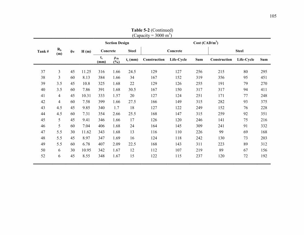
115
Table 5-2 (Continued)
(Capacity = 3000 m3)
Tank # Rb
(m) v H (m)
Section Design Cost (CAD/m3)
Concrete Steel Concrete Steel
tc
(mm) sh
(%)ts (mm) Construction Life-Cycle Sum Construction Life-Cycle Sum
37 3 45 11.25 316 1.66 24.5 129 127 256 215 80 295
38 3 60 8.13 384 1.66 34 167 152 319 356 95 451
39 3.5 45 10.8 325 1.68 22 129 126 255 191 79 270
40 3.5 60 7.86 391 1.68 30.5 167 150 317 317 94 411
41 4 45 10.31 333 1.57 20 127 124 251 171 77 248
42 4 60 7.58 399 1.66 27.5 166 149 315 282 93 375
43 4.5 45 9.85 340 1.7 18 127 122 249 152 76 228
44 4.5 60 7.31 354 2.66 25.5 168 147 315 259 92 351
45 5 45 9.41 346 1.66 17 126 120 246 141 75 216
46 5 60 7.04 406 1.68 24 164 145 309 241 91 332
47 5.5 30 11.62 343 1.68 13 116 110 226 99 69 168
48 5.5 45 8.97 347 1.69 16 124 118 242 130 73 203
49 5.5 60 6.78 407 2.09 22.5 168 143 311 223 89 312
50 6 30 10.95 342 1.67 12 112 107 219 89 67 156
52 6 45 8.55 348 1.67 15 122 115 237 120 72 192
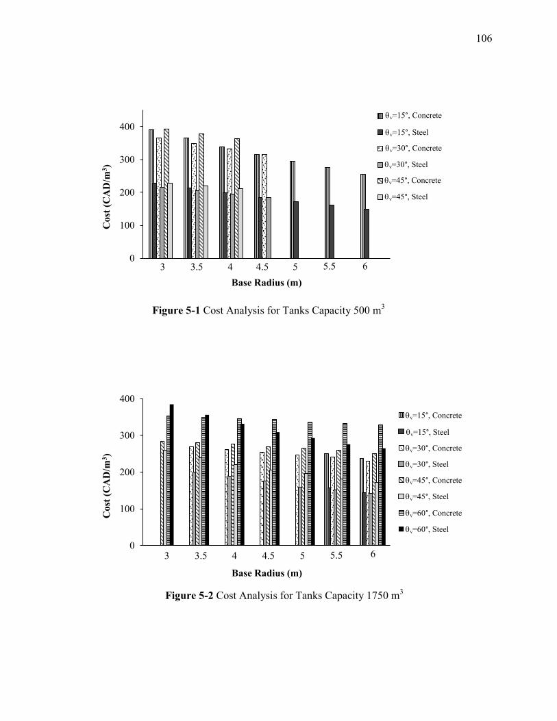
116
Figure 5-2 Cost analysis for tanks capacity 1750 m3
Figure 5-2 Cost Analysis for Tanks Capacity 1750 m
3
v=15°, Concrete
v=15°, Steel
v=30°, Concrete
v=30°, Steel
v=45°, Concrete
v=45°, Steel
0
100
200
300
400
3 3.5 4 4.5 5 5.5 6
Cost
(C
AD
/m3)
Base Radius (m)
Figure 5-1 Cost Analysis for Tanks Capacity 500 m3
3 3.5 4 4.5 5 5.5 6
0
100
200
300
400
3 3.5 4 4.5 5 5.5 6
Co
st (
CA
D/m
3)
Base Radius (m)
v=15°, Concrete
v=15°, Steel
v=30°, Concrete
v=30°, Steel
v=45°, Concrete
v=45°, Steel
3 3.5 4 4.5 5 5.5 6
v=60°, Concrete
v=60°, Steel
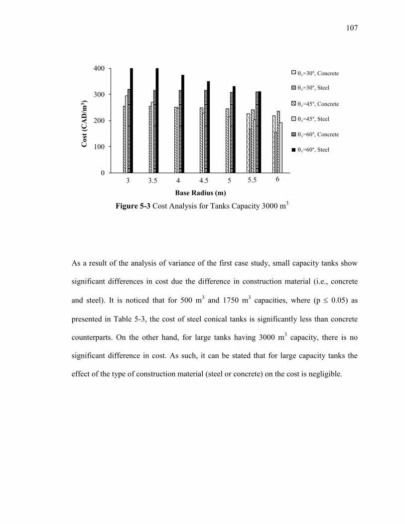
117
As a result of the analysis of variance of the first case study, small capacity tanks show
significant differences in cost due the difference in construction material (i.e., concrete
and steel). It is noticed that for 500 m3 and 1750 m
3 capacities, where (p 0.05) as
presented in Table 5-3, the cost of steel conical tanks is significantly less than concrete
counterparts. On the other hand, for large tanks having 3000 m3 capacity, there is no
significant difference in cost. As such, it can be stated that for large capacity tanks the
effect of the type of construction material (steel or concrete) on the cost is negligible.
0
100
200
300
400
3 3.5 4 4.5 5 5.5 6
Co
st (
CA
D/m
3)
Base Radius (m)
v=30°, Concrete
v=30°, Steel
v=45°, Concrete
v=45°, Steel
3 3.5 4 4.5 5 5.5 6
v=60°, Concrete
v=60°, Steel
Figure 5-3 Cost Analysis for Tanks Capacity 3000 m3
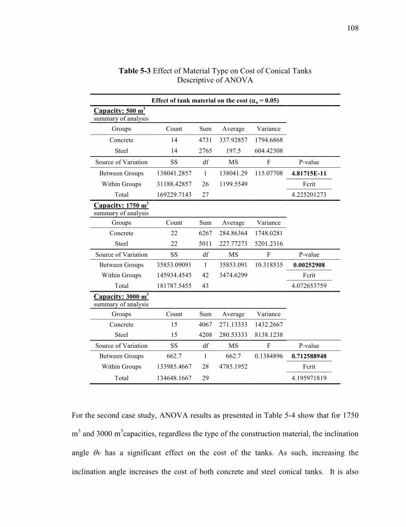
118
Table 5-3 Effect of Material Type on Cost of Conical Tanks
Descriptive of ANOVA
Effect of tank material on the cost (a = 0.05)
Capacity: 500 m3
summary of analysis
Groups Count Sum Average Variance
Concrete 14 4731 337.92857 1794.6868
Steel 14 2765 197.5 604.42308
Source of Variation SS df MS F P-value
Between Groups 138041.2857 1 138041.29 115.07708 4.81715E-11
Within Groups 31188.42857 26 1199.5549
Fcrit
Total 169229.7143 27
4.225201273
Capacity: 1750 m3
summary of analysis
Groups Count Sum Average Variance
Concrete 22 6267 284.86364 1748.0281
Steel 22 5011 227.77273 5201.2316
Source of Variation SS df MS F P-value
Between Groups 35853.09091 1 35853.091 10.318535 0.00252908
Within Groups 145934.4545 42 3474.6299
Fcrit
Total 181787.5455 43
4.072653759
Capacity: 3000 m3
summary of analysis
Groups Count Sum Average Variance
Concrete 15 4067 271.13333 1432.2667
Steel 15 4208 280.53333 8138.1238
Source of Variation SS df MS F P-value
Between Groups 662.7 1 662.7 0.1384896 0.712588948
Within Groups 133985.4667 28 4785.1952
Fcrit
Total 134648.1667 29
4.195971819
For the second case study, ANOVA results as presented in Table 5-4 show that for 1750
m3 and 3000 m
3capacities, regardless the type of the construction material, the inclination
angle v has a significant effect on the cost of the tanks. As such, increasing the
inclination angle increases the cost of both concrete and steel conical tanks. It is also
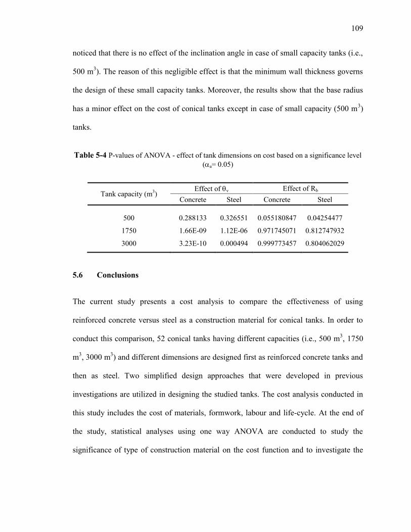
119
noticed that there is no effect of the inclination angle in case of small capacity tanks (i.e.,
500 m3). The reason of this negligible effect is that the minimum wall thickness governs
the design of these small capacity tanks. Moreover, the results show that the base radius
has a minor effect on the cost of conical tanks except in case of small capacity (500 m3)
tanks.
Table 5-4 P-values of ANOVA - effect of tank dimensions on cost based on a significance level
(a= 0.05)
Tank capacity (m3)
Effect of v Effect of Rb
Concrete Steel Concrete Steel
500 0.288133 0.326551 0.055180847 0.04254477
1750 1.66E-09 1.12E-06 0.971745071 0.812747932
3000 3.23E-10 0.000494 0.999773457 0.804062029
5.6 Conclusions
The current study presents a cost analysis to compare the effectiveness of using
reinforced concrete versus steel as a construction material for conical tanks. In order to
conduct this comparison, 52 conical tanks having different capacities (i.e., 500 m3, 1750
m3, 3000 m
3) and different dimensions are designed first as reinforced concrete tanks and
then as steel. Two simplified design approaches that were developed in previous
investigations are utilized in designing the studied tanks. The cost analysis conducted in
this study includes the cost of materials, formwork, labour and life-cycle. At the end of
the study, statistical analyses using one way ANOVA are conducted to study the
significance of type of construction material on the cost function and to investigate the
111
effect of dimension parameters on the cost for both reinforced concrete tanks and steel
counterparts. The main conclusions of this study are listed below:
Compared to reinforced concrete, steel is a more cost-effective construction
material for conical tanks with capacities of 1750 m3 or less. Steel tanks provide a
reduction in the cost up to 42%, and 22% for 500 m3, and 1750 m
3, respectively.
This conclusion can be generally applied for conical tanks having different
dimensions except those tanks with inclination angle 60° and base radiuses of 3 m
and 3.5 m.
For 1750 m3 capacity conical tanks having dimensions of 60° inclination angle and
base radius less than 4 m, reinforced concrete is considered to be more economical
construction material compared to steel.
Cost analysis for conical tanks with 3000 m3 volume shows that concrete is more
economical for tanks that have inclination angle of 60° and base radiuses of (3 m to
3.5 m). For all other studied cases, no general conclusion is reached.
ANOVA technique demonstrates that the angle of wall inclination has the main
effect on the cost of conical tanks as increasing the wall inclination increases the
cost. Moreover, the angles of inclination 15° and 30° are found to be more
economics than angles of 45° and 60° for tanks having the same capacities. On the
other hand, the change in the base radius has a slight effect on the cost function.
The effect of the base radius is only noticed in case of small capacity (500 m3)
tanks, where the increase in base radius leads to a slight reduction in cost.
111
6 CHAPTER 6
CONCLUSIONS
6.1 Summary and Conclusions
This thesis studies the behaviour of reinforced concrete conical tanks under the effect of
hydrostatic pressure. The available design codes provide provisions on rectangular and
cylindrical reinforced concrete tanks and there are no clear guidelines for conical shaped
tanks. As such, there are two main objectives considered in this study. The first objective
is to assess the adequacy of such available codes when applied to conical tanks using an
equivalent cylindrical approach provided by AWWA-D100 (2005). This is achieved by
comparing the internal forces in the tank walls that are predicted according to code
provisions to those obtained from finite element analysis models. These numerical
models are based on a sub-parametric triangular shell element.
The second objective is to make use of the conclusions reached in assessing the adequacy
of available code provisions in order to provide a simple and adequate design approach.
This simplified approach is based on utilizing accurate internal forces predicted by finite
element analysis together with code requirements for serviceability and strength design to
develop a set of design charts. Finally, the developed design charts are validated and
utilized to design and estimate the cost of reinforced concrete conical tanks. The cost of
these tanks is compared to steel counterparts in order to present a comparison between
the two different types of construction materials for conical tanks. Based on all the above
findings, the following conclusions are drawn.
112
The available design codes for reinforced concrete tanks do not provide any clear
provisions for analyzing the forces acting on the walls of conical shaped vessels.
Therefore, there is a need for guidelines for such tanks.
The equivalent cylindrical approach recommended by the AWWA-D100 (2005) is
used to transform the geometry of conical vessels to equivalent cylindrical tanks. A
large disagreement has been found between the maximum forces resulting from the
finite element method and those resulting from the PCA-CCTWP approach
combined with the equivalent cylinder approach. It is noticed that this disagreement
is directly proportional to the wall inclination angle.
The PCA-CCTWP leads to larger hoop tension and smaller meridional moment
compared to internal forces obtained from finite element analysis. Therefore, the
PCA-CCTWP leads to an inadequate design if applied to conical shaped tanks.
The internal forces acting on tank walls obtained from a built in-house finite
element model together with code requirements are successfully employed to
develop a set of simplified design charts. These design charts are developed for a
certain practical range of conical tank dimensions, including tank height, base
radius, and angle of inclination. The accuracy of such charts was also assessed.
The proposed simplified design approach can be generally used for any reinforced
concrete conical tank within the assumed bounds of dimensions. The outputs of this
approach include the wall minimum required thickness and the associated
maximum internal forces.
The developed design charts are utilized to design a number of reinforced concrete
conical tanks then the cost of such tanks is estimated and compared to steel tanks
113
having the same capacity. It is concluded from this comparison that steel tanks are
considered as a more economical choice for medium and small capacity tanks,
regardless their dimensions. On the other hand, for large capacity conical tanks
(more than 1750 m3), the tank dimensions (i.e., tank height, base radius, and angle
of inclination) govern which construction material (reinforced concrete vs. steel) is
more cost effective.
A cost analysis for conical tanks having the same material and specific capacities
has been conducted in order to study the effect of changing dimension parameters
on the cost function. It is concluded that the cost of conical tanks is mainly affected
by the wall inclination angles, which is directly proportional to the cost.
6.2 Recommendations for Future Research
This thesis studies the behaviour and design of reinforced concrete conical tanks having
constant thickness under the effect of hydrostatic pressure. For future research, the
following investigations are recommended:
Study the effects of variable thickness along the tank height on the behaviour of
reinforced concrete conical tanks.
Investigate the non-linear behaviour of reinforced concrete tanks.
Examine the response of reinforced concrete tanks under the effect of
hydrodynamic pressure resulting from earthquake loading.
Deflection of conical tanks should be investigated by using a computer program
that considers cracking ad nonlinearity.
Additional experimental study of wall specimens subjected to both axial tension
and combined meridional moment and axial compression is needed.
114
Assess the effect of pre-stressing on the design procedure of reinforced concrete
conical tanks
Investigate the applicability of using steel/concrete composite section for conical
shaped tanks.
115
REFERENCES
American Concrete Institute (ACI), 1989. Environmental Engineering Concrete
Structures, ACI 350R-89, Detroit, MI.
American Concrete Institute (ACI), 2001, Control of Cracking in Concrete Structures,
ACI 224R, Farmington Hills, MI.
American Concrete Institute (ACI), 2006. Design Considerations for Environmental
Engineering Concrete Structures, ACI 350-01/ACI 350 R-01, Farmington Hills,
MI.
American Petroleum Institute (API), 2005. Welded Storage Tanks for Oil Storage, API
650, American Petroleum Institute Standard, Washington D.C.
American Water Works Association (AWWA), 2005.Welded Steel Tanks for Water
Storage, AWWA D-100, Denver, CO.
Barakat S. A. and Altoubat S., 2009. Application of Evolutionary Global Optimization
Techniques in the Design of R.C. Water Tanks, Journal of Engineering Structures,
Volume 31, Issue 2, pages: 332-344
Barry R., 2001. The Construction of Buildings Volumes 4,5th
ed. London: Blackwell
Science Ltd.; 232 pp.
Bornscheuer F. W., Ramm E., and Stegmuller H., 1983. Stability and Ultimate Load
Analysis of Liquid-Filled Conical Shells, Preliminary Rep., 3rd
Int. Colloquium on
Stability of Metal Struct., Structural Stability Research Council, Bethlehem, pages:
391-398.
Bruder M., 2011. Cylinderical Concrete Tanks with a Conical Base-Internal Force
Discrepancies between Different Analysis Tools, Proceedings of the 2nd
International Engineering Mechanics and Materials Specialty Conference, Ottawa,
Pages: IEMM0071-IEMM00710.
Cheremisinoff P. N., 1996. Advances in Environmental Control Technology, Storage
Tanks Gulf Professional Publishing, Houston, Texas; 303 pp.
Copley J. D., Ward J. S., and Bannister H., 2000. 2.0-Million Gallon Prestressed
Concrete Elevated Tank Frankfort, Kentucky, Proceedings of the American Water
Works Association Conference, AWWA 51525.
Dutta S. C., Dutta S., and Roy R., 2009. Dynamic Behaviour of R/C Elevated Tanks with
Soil-Structure Interaction, Journal of Engineering Structures, Volume 31, Issue 11,
pages: 2617-2629.
116
El Ansary A. M., EL Damatty A. A., and Nassef A. O., 2010. A Coupled Finite Element
Genetic Algorithm Technique for Optimum Design of Steel Conical Tanks, Journal
of Thin-Walled Structures, Volume 48, pages: 260 – 273
El Ansary A. M., El Damatty A. A., and Nassef A.O., 2011. A Coupled Finite Element
Genetic Algorithm for Optimum Design of Stiffened Liquid-Filled Steel Conical
Tanks, Thin-Walled Structures, Volume 49, No. 4, pages: 482-493.
El Damatty A. A., El-Attar M., and Korol M., 1998. Inelastic Stability of Conical Tanks.
Journal of Thin-Walled Structures, Volume 31, pages 343-359.
El Damatty A. A., Mirza F. A., and Korol R. M., 1997. Large Displacement Extension of
Consistent Shell Element for Static and Dynamic Analysis, Journal of Computers
and Structures, Volume 62, Issue: 6, pages 943-960.
El Damatty A. A., 1995. Non-Linear Dynamic Extension of Consistent Shell Element and
Analysis of Liquid-Filled Conical Tanks, PhD Thesis, McMaster University
El Damatty A. A., El Attar M., Korol M., 1998. Inelastic Stability of Conical Tanks.
Journal of Thin-Walled Structures, Volume 31, pages 343-359.
El Damatty A. A., El Attar M., Korol M., 1999. Simple Design Procedure for
LiquidFilled Steel Conical Tanks. Journal of Structure Engineering, ASCE,
Volume 125, Issue 8, pages 879-90.
El Damatty A. A., Korol R. M., and Mirza F. A., 1997. Stability of Imperfect Conical
Tanks under Hydrostatic Loading, Journal of Structural Engineering, ASCE,
Volume 123, Issue 6, pages: 703-712.
EL Reedy M. A., 2011. Construction management and design of industrial concrete and
steel structures, Taylor & Francis Group; 576 pp.
Frosch R. J., 1999. Another Look at Cracking and Crack Control in Reinforced Concrete.
ACI Struct. Journal, Volume 96, Issue 3, pages:437-42.
Ghali A., 1979. Circular Storage Tanks and Silos. E. & F.N. Spon Limited, London;
330 pp.
Ghali A., 2000. Circular Storage Tanks and Silos. E. & F.N. Spon Limited, London;
443 pp.
Godbout S., Marquis A., Fafard M., and Picard A., 2003, Analytical Determination of
Internal Forces in a Cylindrical Tank Wall from Soil, Liquid, and Vehicle Loads,
Canadian Biosystems Engineering, Volume 45, pages: 5.7-5.14.
117
Gray W. S., 1948. Reinforced Concrete Reservoirs and Tanks. Concrete Publications
Limited, London; 189 pp.
Grieve R., Slater W. M., and Rothenburg L., 1987. Deterioration of above ground
concrete water tanks in Ontario, Ministry of the Environment, Report. Toronto,
Ontario, Canada; 124 pp.
Hafeez G., El Ansary A. M. and El Damatty A. A., 2010. Stability of Combined
Imperfect Conical Tanks under Hydrostatic Loading. Journal of Constructional
Steel Research, Volume.66, pages: 1387-97.
Hafeez G., El Ansary A. M. and El Damatty A. A., 2011. Effect of Wind Loads on the
Stability of Conical Tanks. Canadian Journal for Civil Engineers, Volume 38, Issue
4, pages: 444-454.
Hilal M., 1988. Theory and Design of Reinforced Concrete Tanks. J & Marcou, Cairo,
Egypt; 402 pp.
Kamal C. S. and Hoijat A. D., 1998. Cost Optimization of Concrete Structures, Journal of
Structural Engineering, Volume 124, Issue 5, pages: 570-78.
Kamara M. E., 2010. Design of Circular Concrete Tanks, Proceedings of the Structures
Congress, May12-15, Orlando, Florida, pages: 2439-2449.
Koziey B. and Mirza F. A., 1997. Consistent Thick Shell Element, Journal of Computers
and Structures, Volume 65, Issue: 12, pages: 531-541.
Koziey B., 1993. Formulation and Application of Consistent Shell and Beam Elements
Ph.D. Thesis, McMaster University, Hamilton, Ontario, Canada.
Lagae G.A.M.E., Vanlaere W. M. H., and Impe, R. E. V., 2007. Plastic Buckling of
Conical Tanks with Large Geometrical Imperfections, Rene Maquoi 65th
Birthday
Anniversary, Liège, Belgium.
Meier S. W., 2002. Today’s Composite Elevated Storage Tanks, Tank Industry
Consultants, Indianapolis, IN.
Portland Cement Association (PCA-CCTWP), 1993. Circular Concrete Tanks without
Prestressing, Skokie, Illinois.
Rai D. C., 2003. Performance of Elevated Tanks in Mw 7.7 Bhuj Earthquake of January
26th
2001, Proc Indian AcadSci – Earth Planet Sci, Volume 112, Issue 3, Pages:
421-429.
Rai D.C., 2002. Seismic Retrofitting of R/C Shaft Support of Elevated Tanks, Earthquake
Spectra, Volume 18, Issue 4, pages: 745-760.
118
Ross D. H., 2001. Infrastructure Research Needs: A Public Works Perspective,
Proceeding of First Annual Conference on Infrastructure Priorities: A National
Infrastructure Research Agenda, October 24-26, Washington, D.C., USA.
Saxena M. S. and Mohan C., 1987. Cost Optimization of Intze Tanks on Shafts Using
Nonlinear Programming, Engineering Optimization, Volume 10, Issue 4, pages:
279-88.
Sezen H., Livaoglu R., Dogangun A., 2008. Dynamic Analysis and Seismic Performance
Evaluation of Above Ground Liquid Containing Tanks, Journal of Engineering
Structures, Volume 30, Issue 3, Pages: 794-803.
Slater G. S., 1940. Design of Circular Concrete Tanks.Transaction of the American
Society of Civil Engineers, Volume 105; 504 pp.
Stamatis D. H., 2002. Six Sigma and Beyond, Design of Experiments, CRC Press,
eBook, Volume V, pages: 381-97.
Sweedan A. M. I., and El Damatty A. A., 2002. Experimental and Analytical Evaluation
of the Dynamic Characteristics of Conical Shells, Journal of Thin-Walled
Structures, Volume 40, pages: 465-486.
Sweedan A. M. I., and El Damatty A. A., 2009. Simplified Procedure for Design of
Liquid-Storage Combined Conical Tanks, Journal of Thin-Walled Structures,
Volume 47, pages: 750-759.
Timoshenko S., and Woinowski-Krieger S., 1959. Theory of Plates and Shell,
McGrawhill.
Vandepitte D., 1999. Confrontation of Shell Buckling Research Results with the Collapse
of a Steel Water Tower, Journal of Constructional Steel Research, Volume 49,
Issue 3, pages: 303-314.
Vandepitte D., Rathe J., Verhegghe B., Paridaens R., and Verschaeve C., 1982.
Experimental Investigation of Hydrostatically Loaded Conical Shells and Practical
Evaluation of the Buckling Load, Proc. State-of-the-Art Colloquium, Universitat
Stuttgart, Germany, pages: 375-399.
Wilby A. C., 1977. Structural Analysis of Reinforced Concrete Tanks, Journal of the
Structural Division, ASCE, Volume 103, No. ST5, pages: 989-1004.
Ziari A., and Kianoush M.R., 2009, Investigation of Direct Tension Cracking and
Leakage in R.C. elements, Journal of Engineering Structures, Volume 31, Issue 2,
pages: 466-474.
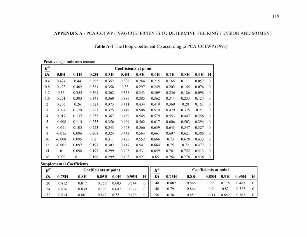
119
7 APPENDIX A - PCA-CCTWP (1993) COEFFICIENTS TO DETERMINE THE RING TENSION AND MOMENT
Table A-1 The Hoop Coefficient CH according to PCA-CCTWP (1993)
Positive sign indicates tension
Coefficients at point
0.0H 0.1H 0.2H 0.3H 0.4H 0.5H 0.6H 0.7H 0.8H 0.9H H
0.4 0.474 0.44 0.395 0.352 0.308 0.264 0.215 0.165 0.111 0.057 0
0.8 0.423 0.402 0.381 0.358 0.33 0.297 0.249 0.202 0.145 0.076 0
1.2 0.35 0.355 0.361 0.362 0.358 0.343 0.309 0.256 0.186 0.098 0
1.6 0.271 0.303 0.341 0.369 0.385 0.385 0.362 0.314 0.233 0.124 0
2 0.205 0.26 0.321 0.373 0.411 0.434 0.419 0.369 0.28 0.151 0
3 0.074 0.179 0.281 0.375 0.449 0.506 0.519 0.479 0.375 0.21 0
4 0.017 0.137 0.253 0.367 0.469 0.545 0.579 0.553 0.447 0.256 0
5 -0.008 0.114 0.235 0.356 0.469 0.562 0.617 0.606 0.503 0.294 0
6 -0.011 0.103 0.223 0.343 0.463 0.566 0.639 0.643 0.547 0.327 0
8 -0.015 0.096 0.208 0.324 0.443 0.564 0.661 0.697 0.621 0.386 0
10 -0.008 0.095 0.2 0.311 0.428 0.552 0.666 0.73 0.678 0.433 0
12 -0.002 0.097 0.197 0.302 0.417 0.541 0.664 0.75 0.72 0.477 0
14 0 0.098 0.197 0.299 0.408 0.531 0.659 0.761 0.752 0.513 0
16 0.002 0.1 0.198 0.299 0.403 0.521 0.65 0.764 0.776 0.536 0
Supplemental Coefficients
Coefficients at point
0.75H 0.8H 0.85H 0.9H 0.95H H
20 0.812 0.817 0.756 0.603 0.344 0
24 0.816 0.839 0.793 0.647 0.377 0
32 0.814 0.861 0.847 0.721 0.436 0
Coefficients at point
0.75H 0.8H 0.85H 0.9H 0.95H H
40 0.802 0.866 0.88 0.778 0.483 0
48 0.791 0.864 0.9 0.82 0.527 0
56 0.781 0.859 0.911 0.852 0.563 0
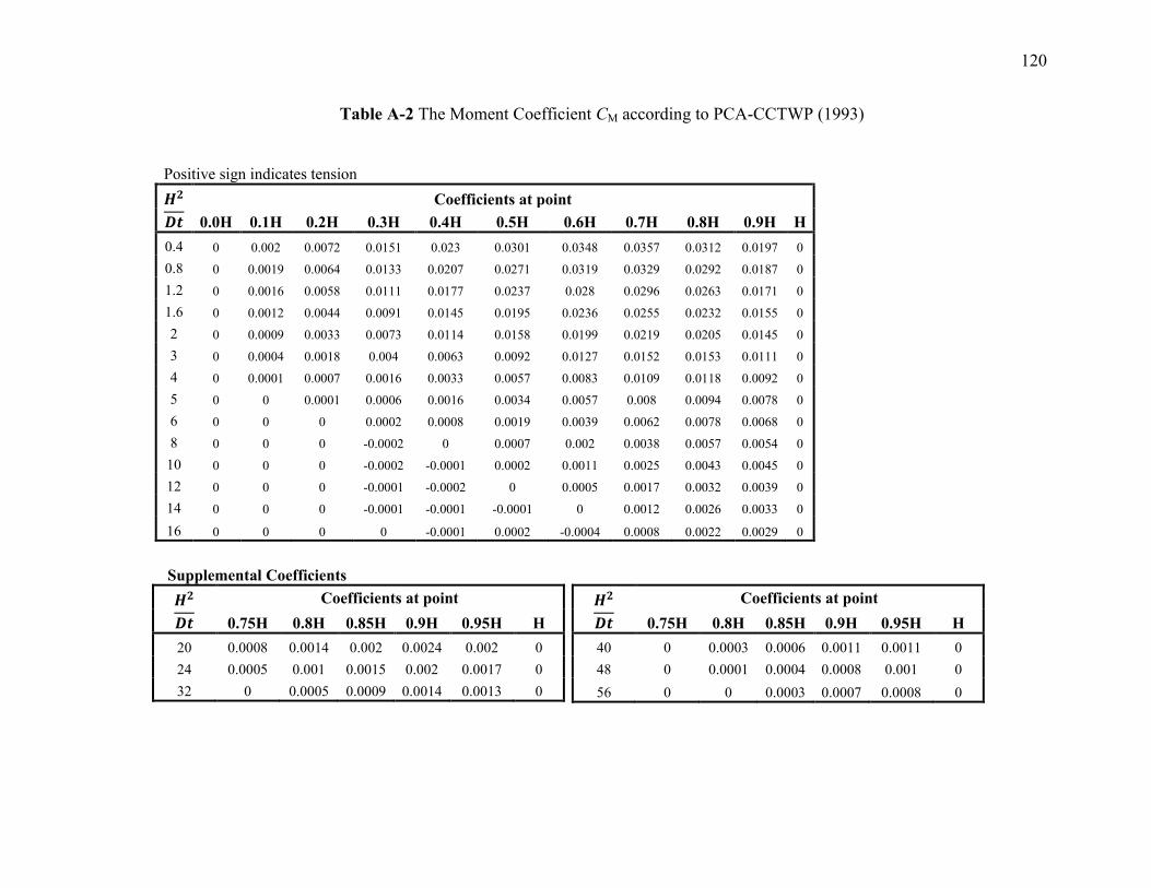
121
Table A-2 The Moment Coefficient CM according to PCA-CCTWP (1993)
Positive sign indicates tension
Coefficients at point
0.0H 0.1H 0.2H 0.3H 0.4H 0.5H 0.6H 0.7H 0.8H 0.9H H
0.4 0 0.002 0.0072 0.0151 0.023 0.0301 0.0348 0.0357 0.0312 0.0197 0
0.8 0 0.0019 0.0064 0.0133 0.0207 0.0271 0.0319 0.0329 0.0292 0.0187 0
1.2 0 0.0016 0.0058 0.0111 0.0177 0.0237 0.028 0.0296 0.0263 0.0171 0
1.6 0 0.0012 0.0044 0.0091 0.0145 0.0195 0.0236 0.0255 0.0232 0.0155 0
2 0 0.0009 0.0033 0.0073 0.0114 0.0158 0.0199 0.0219 0.0205 0.0145 0
3 0 0.0004 0.0018 0.004 0.0063 0.0092 0.0127 0.0152 0.0153 0.0111 0
4 0 0.0001 0.0007 0.0016 0.0033 0.0057 0.0083 0.0109 0.0118 0.0092 0
5 0 0 0.0001 0.0006 0.0016 0.0034 0.0057 0.008 0.0094 0.0078 0
6 0 0 0 0.0002 0.0008 0.0019 0.0039 0.0062 0.0078 0.0068 0
8 0 0 0 -0.0002 0 0.0007 0.002 0.0038 0.0057 0.0054 0
10 0 0 0 -0.0002 -0.0001 0.0002 0.0011 0.0025 0.0043 0.0045 0
12 0 0 0 -0.0001 -0.0002 0 0.0005 0.0017 0.0032 0.0039 0
14 0 0 0 -0.0001 -0.0001 -0.0001 0 0.0012 0.0026 0.0033 0
16 0 0 0 0 -0.0001 0.0002 -0.0004 0.0008 0.0022 0.0029 0
Supplemental Coefficients
Coefficients at point
0.75H 0.8H 0.85H 0.9H 0.95H H
20 0.0008 0.0014 0.002 0.0024 0.002 0
24 0.0005 0.001 0.0015 0.002 0.0017 0
32 0 0.0005 0.0009 0.0014 0.0013 0
Coefficients at point
0.75H 0.8H 0.85H 0.9H 0.95H H
40 0 0.0003 0.0006 0.0011 0.0011 0
48 0 0.0001 0.0004 0.0008 0.001 0
56 0 0 0.0003 0.0007 0.0008 0
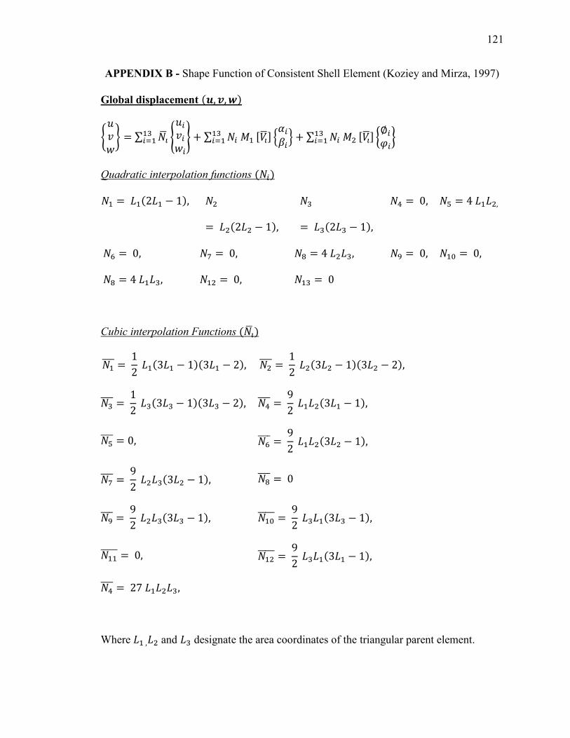
121
APPENDIX B - Shape Function of Consistent Shell Element (Koziey and Mirza, 1997)
Global displacement (
{ } ∑
{
} ∑ [ ] {
} ∑
[ ] {
}
Quadratic interpolation functions (
(
(
(
Cubic interpolation Functions (
( (
( (
( (
(
(
(
(
(
(
Where and designate the area coordinates of the triangular parent element.
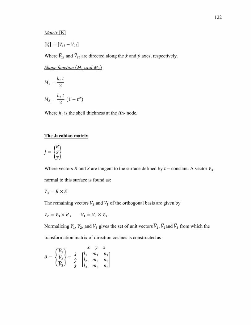
122
Matrix [ ]
[ ] [ ]
Where and are directed along the and axes, respectively.
Shape function (
(
Where is the shell thickness at the th- node.
The Jacobian matrix
{ }
Where vectors and are tangent to the surface defined by = constant. A vector
normal to this surface is found as:
The remaining vectors and of the orthogonal basis are given by
Normalizing , , and gives the set of unit vectors , and from which the
transformation matrix of direction cosines is constructed as
{
}
[
]
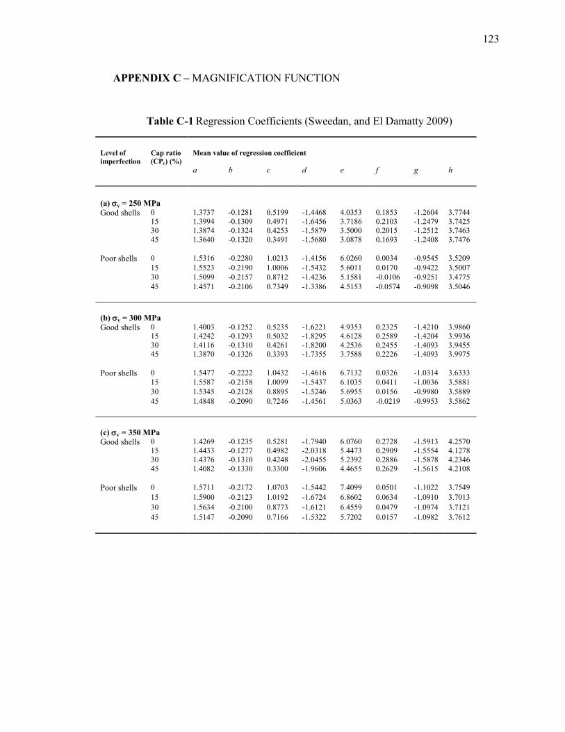
123
8 APPENDIX C – MAGNIFICATION FUNCTION
Table C-1 Regression Coefficients (Sweedan, and El Damatty 2009)
Level of
imperfection
Cap ratio
(CPr) (%)
Mean value of regression coefficient
a b c d e f g h
(a) y = 250 MPa
Good shells 0 1.3737 -0.1281 0.5199 -1.4468 4.0353 0.1853 -1.2604 3.7744
15 1.3994 -0.1309 0.4971 -1.6456 3.7186 0.2103 -1.2479 3.7425
30 1.3874 -0.1324 0.4253 -1.5879 3.5000 0.2015 -1.2512 3.7463
45 1.3640 -0.1320 0.3491 -1.5680 3.0878 0.1693 -1.2408 3.7476
Poor shells 0 1.5316 -0.2280 1.0213 -1.4156 6.0260 0.0034 -0.9545 3.5209
15 1.5523 -0.2190 1.0006 -1.5432 5.6011 0.0170 -0.9422 3.5007
30 1.5099 -0.2157 0.8712 -1.4236 5.1581 -0.0106 -0.9251 3.4775
45 1.4571 -0.2106 0.7349 -1.3386 4.5153 -0.0574 -0.9098 3.5046
(b) y = 300 MPa
Good shells 0 1.4003 -0.1252 0.5235 -1.6221 4.9353 0.2325 -1.4210 3.9860
15 1.4242 -0.1293 0.5032 -1.8295 4.6128 0.2589 -1.4204 3.9936
30 1.4116 -0.1310 0.4261 -1.8200 4.2536 0.2455 -1.4093 3.9455
45 1.3870 -0.1326 0.3393 -1.7355 3.7588 0.2226 -1.4093 3.9975
Poor shells 0 1.5477 -0.2222 1.0432 -1.4616 6.7132 0.0326 -1.0314 3.6333
15 1.5587 -0.2158 1.0099 -1.5437 6.1035 0.0411 -1.0036 3.5881
30 1.5345 -0.2128 0.8895 -1.5246 5.6955 0.0156 -0.9980 3.5889
45 1.4848 -0.2090 0.7246 -1.4561 5.0363 -0.0219 -0.9953 3.5862
(c) y = 350 MPa
Good shells 0 1.4269 -0.1235 0.5281 -1.7940 6.0760 0.2728 -1.5913 4.2570
15 1.4433 -0.1277 0.4982 -2.0318 5.4473 0.2909 -1.5554 4.1278
30 1.4376 -0.1310 0.4248 -2.0455 5.2392 0.2886 -1.5878 4.2346
45 1.4082 -0.1330 0.3300 -1.9606 4.4655 0.2629 -1.5615 4.2108
Poor shells 0 1.5711 -0.2172 1.0703 -1.5442 7.4099 0.0501 -1.1022 3.7549
15 1.5900 -0.2123 1.0192 -1.6724 6.8602 0.0634 -1.0910 3.7013
30 1.5634 -0.2100 0.8773 -1.6121 6.4559 0.0479 -1.0974 3.7121
45 1.5147 -0.2090 0.7166 -1.5322 5.7202 0.0157 -1.0982 3.7612
124
9 CURRICULUM VITAE
Name: Tareq Azabi
Post-Secondary
Education and
Degrees:
B.Sc. 1995-2000
Civil and Environmental Engineering Department
Faculty of Engineering – Tripoli University (Former; Al-Fateh
University)
Tripoli, Libya
Honors and
Awards:
Post Graduate External Scholarship, The Libyan Authority of
Higher Education. Libya, 2011-2013
Academic
Appointments:
Teaching Assistant
Department of Civil and Environmental Engineering
The University of Western Ontario, Canada, 2011-2013
Professional
Appointments:
Sales Engineer
Sika Technologies for Construction Chemicals
Tripoli, Libya. 2004-2010
Structural Engineer
Bonyan Consulting Engineers
Tripoli, Libya. 2001-2004
In-Training Civil Engineer
Bonyan Consulting Engineers
Tripoli, Libya. 2000-2001


![Performance of IBA New Conical Shaped Niobium [18O] Water ... · Vienna sept 2010, poster #9, session P13. Table 2: Results Summary Conical 6 Conical 8 Conical 12 Conical 16 Insert](https://img.pdfslide.us/doc/110x75/5f901a7319a03054823be5c3/performance-of-iba-new-conical-shaped-niobium-18o-water-vienna-sept-2010.jpg)