Embed Size (px)
Citation preview

Journal of Theoretical and Applied Mechanics, Sofia, 2015, vol. 45, No. 3, pp. 83–96
BEHAVIOUR OF BI-ADHESIVE IN DOUBLE-STRAP
JOINT WITH EMBEDDED PATCH SUBJECTED TO
BENDING∗
Semsettin Tem.iz, Hamit Ad
.in
Department of Mechanical Engineering, Faculty of Engineering,
Batman University, 72060 Batman, Turkey,
e-mails:[email protected], [email protected]
Ismail Yasin S..ul
..u
Department of Mechanical Engineering, Faculty of Engineering,
Inonu University, 44280 Malatya, Turkey
e-mail:[email protected]
[Received 20 April 2015. Accepted 15 June 2015]
Abstract. In this study, behaviour of bi-adhesive used in the repairof damaged parts was analyzed, using the finite element method. Ina double-strap joint with an embedded patch, patch is embedded intothe adherents for structural requirements. In addition, to increase thestrength of the joint, two adhesives are used to bond the adherents. Thisapproach reduces stress concentration at the overlap ends, increases theload capacity and delays the failure. These effects give rise to higher jointstrength. For this purpose, a stiff adhesive, FM73 produced by CytecFiberite, was applied in the middle portion of the overlap, while a softeradhesive, SBT9244 from 3M, was applied towards the edges, prone tostress concentrations. Non-linear finite element analyses were carried outto predict the failure loads, to assist with the geometric design and toidentify effective ratios of sizes to maximize joint strength.Key words: Bi-adhesive, double-strap joints, finite element analysis,mechanical properties, stress analysis, failure loads.
1. Introduction
The classical double-strap adhesive joint is preferred in both bondingand repair of damaged parts, particularly in the aircraft and automotive indus-tries [1–5]. In the classical double-strap joint, patches form protrusions at the
*Corresponding author e-mail: [email protected]

84 Semsettin Temiz, Ismail Yasin Sulu, Hamit Adin
outer surface, which limits backward, forward and circular mobility of the partsonly in narrow areas. Double-strap joint with embedded patch eliminates theseprotrusions, therefore, the movement restrictions are removed and smoothersurfaces are obtained. In addition, coating and painting operations are easierover the obtained smoother surfaces, and a better view is obtained in terms ofconstruction and aesthetic [6].
The reduction of transverse shear and normal stress concentrationsalong the edges of adhesive bondlines is important, in order to prevent prema-ture failure of the bonded joint. Due to differential straining in the substrates,adhesively-bonded joints inevitably experience stress concentrations, especiallyin the adhesive layer near the ends of overlap, where the load transfer takesplace. Among the many factors affecting the strength of a bonded joint, thestresses in both the adhesive layer and the substrates are probably most crucialto the design of bonded joints [7–10].
Geometric modifications, such as adhesive spew fillet, adherent and ad-hesive rounding, adherent shaping, e.g., chamfering, adhesive gaps and adhesivegrading have significant influence on the reduction of peak stresses, occurringat the ends of the overlap in adhesively bonded joints [6]. Therefore, many ap-proaches have been proposed to reduce the peak stresses [11–13]. Applicationsof spew fillet and bi-adhesives are examples of these approaches. Performanceof bi-adhesives has been studied in single-lap and double-strap joints and mea-surable increase in the strength of the bi-adhesively-bonded joints is found,when compared with those in which single adhesives were used over the fulllength of the bondline [14–19]. Despite the material properties, the adhesivejoint geometry also led to stress concentration areas in the adhesive/adherentinterface, revealed at the edges of the overlap. However, for a given adher-ent, the lower the stiffness of the adhesive used in the overlap, the lower thestress concentration, leading to potentially higher joint strength. The use ofrelatively low stiffness adhesives at the ends of the overlap in a bi-adhesive candecrease the stress concentration and, therefore, potentially lead to higher jointstrength.
In this study, the application of two adhesives with different stiffnessin double-strap joints with embedded patch, subjected to bending moment,was investigated via non-linear Finite Element Analysis (FEA), and the stressdistributions in the joints were analyzed. This study is part of an Msc Thesisproject. The next step of this study is to perform an experimental work and val-idate the results with the experimental testing. The same geometry, material,and loading were used in this study, as stated in the Msc Thesis project.
Behaviour of Bi-Adhesive in Double-Strap Joint . . . 85
2. Non-Linear Finite Element Modelling of The Double-StrapJoint (DSJ)
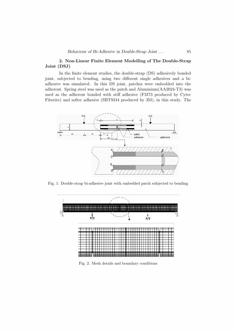
In the finite element studies, the double-strap (DS) adhesively bondedjoint, subjected to bending, using two different single adhesives and a bi-adhesive was simulated. In this DS joint, patches were embedded into theadherent. Spring steel was used as the patch and Aluminium(AA2024-T3) wasused as the adherent bonded with stiff adhesive (FM73 produced by CytecFiberite) and softer adhesive (SBT9244 produced by 3M), in this study. The
Fig. 1. Double-strap bi-adhesive joint with embedded patch subjected to bending
Fig. 2. Mesh details and boundary conditions

86 Semsettin Temiz, Ismail Yasin Sulu, Hamit Adin
stiff adhesive was located in the middle and the softer adhesive was located atthe ends. The joint configuration and the mesh details considered in this studyare represented in Figs 1 and 2, respectively.
In the analysis, the material non-linearity based on the uniaxial stress-strain behaviours of adhesives (FM73 and SBT9244) and adherent (AA2024-T3) was considered (Fig. 3). The stresses in the patch were below the yieldstress of the patch and, therefore, the patch was modelled as a linear-elasticisotropic material. More information on the stress-strain of adhesive and ad-herent can be found in [6, 14, 20].
Fig. 3. Tensile stress-strain curves of adherent, adhesive and patch: (a) AA2024-T3alloy; (b) Spring steel; (c) FM73 adhesive; (d) SBT9244 adhesive
The effects of different parameters on bonding failure load and jointstrength were investigated in this study. These parameters are patch thickness(h1), total overlap length (L), the length of the embedding part, which isembedded in the main adherent (h) and the depth of the embedding part (t).
The material properties used in the FEM analysis are given in Table

Behaviour of Bi-Adhesive in Double-Strap Joint . . . 87
Table 1. Material properties of the adherent, adhesive and patch used
AA2024-T3 Alloy FM73 Adhesive SBT9244 Adhesive Spring Steel
Ea (MPa) 71875 2093.9 82.80 220000
νe 0.33 0.35 0.35 0.30
σy (MPa) 430 48 4.5 1280
σt (MPa) 482 51.05 20.97 1482
εt 0.16 0.11 0.94 0.06
Ea: Young’s modulus; νe: Poisson’s ratio; σy: Yield strength; σt: Ultimate tensilestrength, εt: Ultimate tensile strain
1. In order to determine the mechanical properties of materials used in thisstudy were prepared as described in Ref. [6]. The geometrical parametersof the joints are shown in Table 2. The thicknesses of adhesive were chosenas 0.25 mm. In addition, the width of adherent was chosen as 25 mm. Theother dimensions of the DLJs are shown in Fig. 2. Since effects of thicknessand overlap length were examined, the same element dimension was used inall models as often as practicable (see in Table 1 and Fig. 3a). The upperand the lower patch plates have the same dimensions and materials. Threedifferent adherent thickness, patch thickness and overlap length were used.Also, the stress analysis of double-strap joints with embedded patch (DSJEP)under a bending moment was carried out, based on plane strain assumption.The von Mises yield criterion was used to calculate the equivalent stress (σeqv)and strain (εeqv) distributions in the adhesive layers and adherents. 2D non-linear FEM was carried out in the analysis of double-strap adhesively-bondedjoints with embedded patch. The ANSYS [21] code version 12.0 and the 8-node isoparametric quadrilateral plane element, Plane 82, were employed forthe DSJ. The 8-node element is defined with eight nodes having two degreesof freedom at each node, i.e. translation in the nodal x and y directions.Mesh distribution area is shown in detail in Fig. 2. Critical regions of stressdistributions at the bonding area were divided into smaller elements. Theadherent and the adhesive were modelled as different areas and joined witheach other using merged nodes. The meshing in adhesive region was performedin a more sensitive manner by dividing it into small pieces [6, 14, 22, 23].In order to perform the stress analysis of the adhesive, elements at adhesiveregion and at the overlapping planes have been prepared with high density;and elements of outside parts of adhesive regions have been prepared with lowdensity. A refined mesh was used in the contacting surfaces in order to achieve

88 Semsettin Temiz, Ismail Yasin Sulu, Hamit Adin
Table 2. Geometrical parameters and failure loads, P of joints
AdherendThickness
(h)(mm)
PatchThickness
(h1)(mm)
OverlapLength,
(L)(mm)
PSBT9244
(N)PFM73
(N)PBI−ADHES
(N)
L1/L2
of BI–
ADHES
(PBI−ADHES − PFM73)
PBI−ADH
(%)
15 1225 2050 2275 0.4 10
0.4 25 1175 1950 2475 0.4 21
35 1325 1900 2600 0.4 27
15 1100 1800 2000 0.4 10
4.8 0.6 25 1200 1575 2275 0.4 31
35 1325 1575 2275 0.4 31
15 1325 1425 1900 0.4 25
0.8 25 1375 1300 1875 0.4 31
35 1425 1300 1850 0.4 30
15 1275 2550 3150 0.2 19
0.4 25 1500 2650 3400 0.2 22
35 1700 2700 3650 0.6 26
15 1325 2475 2700 0.4 8
5.6 0.6 25 1500 2550 3075 0.4 17
35 1650 2400 3175 0.6 25
15 1875 2150 2350 0.4 9
0.8 25 1575 1850 2800 0.4 34
35 1675 1875 2925 0.4 36
15 1625 3300 4175 0.2 21
0.4 25 1875 3475 4475 0.2 22
35 2100 3525 4750 0.6 26
15 1650 2825 3550 0.4 20
6.4 0.6 25 1825 2900 4025 0.4 28
35 2025 2925 4175 0.6 30
15 2225 2450 3050 0.4 20
0.8 25 1925 2500 3825 0.4 35
35 2025 2500 3900 0.4 36
the convergence and get more contact detection points. All elements in thebondlines of the adhesives were of equal size. This fact was important in orderto prevent any problems as the graduation point of the bond-length ratios inthe bi-adhesive bondlines varied [24]. The mesh density can affect the strainpredictions in the adhesive layer. A smaller element size will generally give a

Behaviour of Bi-Adhesive in Double-Strap Joint . . . 89
higher strain. For this reason, the size of the elements in the mesh was reduceduntil a stable strain value had been achieved. Consequently, four elementsthrough the adhesive thickness were used in the models, as shown in Fig. 2,and the number of elements was varied for each overlap length. However, themesh size was kept constant in all models [14].
In the joints with a bi-adhesive, a length L1from the ends of the overlapwas assumed to be bonded with the SBT9244, and the central region was as-sumed to be bonded with the FM73 adhesive. The nominal bondline thicknessconsidered in all cases was 0.25 mm.
3. Results and discussion
3.1. Effect of bi-adhesive on failure load
In this study, the half length of the overlap, assumed to be bonded withbi-adhesive, was denoted with L2 and the length from the ends of the overlap,assumed to be bonded with SBT9244, was denoted with L1. The failure loadsof the DSJEP for different adherent and patch thickness, overlap length andL1/L2 ratios of bi-adhesive are given in Table 2 and shown in Fig. 4. In thefigures, at L1/L2 = 0, joints are bonded with FM73 adhesive alone and atL1/L2 = 1, joints are bonded with SBT9244 adhesive alone. In order to predictthe failure load, the ultimate strain (εt), given in Table 1, for the adhesiveswas used. The equivalent stress (σeqv) and strain (εeqv) were calculated usingthe von Misses yield criterion and it was assumed, that the failure occurredwhen the equivalent strain (εeqv) calculated at any point of the adhesive layerreached the ultimate strain (εt) of the adhesive, given in Table 1. A solutionin finite element analysis, considering non-linear material behaviour, is reachedby dividing the total load in steps to track the equilibrium paths and iteratingto a converged solution at each load increment. Hence, a load of 5 N per mmwidth at each load step was applied for all joint types. The remaining load wasthen applied in the last step [14].
The results in Table 2 show that, except for the failure loads of the twojoints with 4.8 mm adherent and 0.8 mm patch thicknesses, the failure loadsof all the joints, bonded with FM73 alone are greater than the failure loads ofall the joints, bonded with SBT9244 alone. The increase ratio in failure loads,due to using bi-adhesive, varies between 9% and 56%. The maximum predictedfailure loads of the joints with bi-adhesive are at about L1/L2 = 0.2−0.6 lengthratios.
In Fig. 4(a), the effects of bi-adhesive ratio (L1/L2) and adherent thick-ness h on failure loads of DSJEP for h1 = 0.6 mm thick patch are plotted. When

90 Semsettin Temiz, Ismail Yasin Sulu, Hamit Adin
Fig. 4. Comparison of failure loads for double-strap joints with embeddedpatch with single- and bi-adhesive. (a) Joints with different adherent thicknesses(L = 12.5 mm, h1 = 0.6 mm); (b) Joints with different patch thicknesses(L = 12.5 mm, h = 5.6 mm); (c) joints with different overlap lengths (h = 5.6
mm, h1 = 0.6 mm)

Behaviour of Bi-Adhesive in Double-Strap Joint . . . 91
the figure is examined, it is seen that the effect of the bi-adhesive on the failureloads increases with increase in adherent thickness h. In addition, the differ-ence between failure loads of the joint, bonded with FM73 alone (L1/L2 = 0)and failure loads of the joint, bonded with SBT9244 alone (L1/L2 = 1) in-crease with increasing adherent thickness h. For three adherent thicknesses,the maximum failure loads of the bi-adhesive occur in L1/L2 = 0.4.
The effects of the bi-adhesive, depending on patch thickness h1, onfailure loads for 5.6 mm adherent thickness h and 25 mm overlap length L aregiven in Fig. 4(b). For the joint bonded with SBT9244 alone (L1/L2=1), thefailure loads of the joints with three patch thickness h1 are close to each other.Whereas, the failure loads of the joints bonded with FM73 alone (L1/L2 = 0)decreases with increase in the patch thickness. The increase ratio in failureload due to using bi-adhesive reaches 51%, especially in the joint with 0.8 mmpatch thickness h1.
The effect of application of bi-adhesive in double-strap joints with em-bedded patch for different overlap lengths L is shown in Fig. 4(c). For all threeoverlap lengths, the failure loads of joints, bonded with FM73 adhesive alone(L1/L2 = 0) are almost the same. However, the failure loads of the joints,bonded with SBT9244 alone (L1/L2 = 1) increase with increase in the overlaplength L. The increase ratio in failure load due to using bi-adhesive increaseswith increasing the overlap length.
Fig. 5. Equivalent stress distributions along the different bondlines (shown in Fig. 1)on the adhesive side for the DSJ with 5.6 mm adherent thickness for FM73 adhesive

92 Semsettin Temiz, Ismail Yasin Sulu, Hamit Adin
3.2. Effect of bi-adhesive on stress distribution
To compare the stress distributions of the joints with one adhesive aloneand bi-adhesive and to observe the effect of bi-adhesive on stress distributionsof double-strap joints with embedded patch, only the joint with 5.6 mm ad-herent thickness h, 25 mm overlap length L and 0.6 mm patch thickness h wasanalyzed. Here, the joint was subjected to 1000 N bending load.
Fig. 6. longitudinal and peel stress distributions along A–B on the adhesive side fordifferent L1/L2 ratios with 5.6 mm thick adherents, 0.6 mm thick patch and 12.5 mm
overlap length; (a) σx, (b) σy
Behaviour of Bi-Adhesive in Double-Strap Joint . . . 93
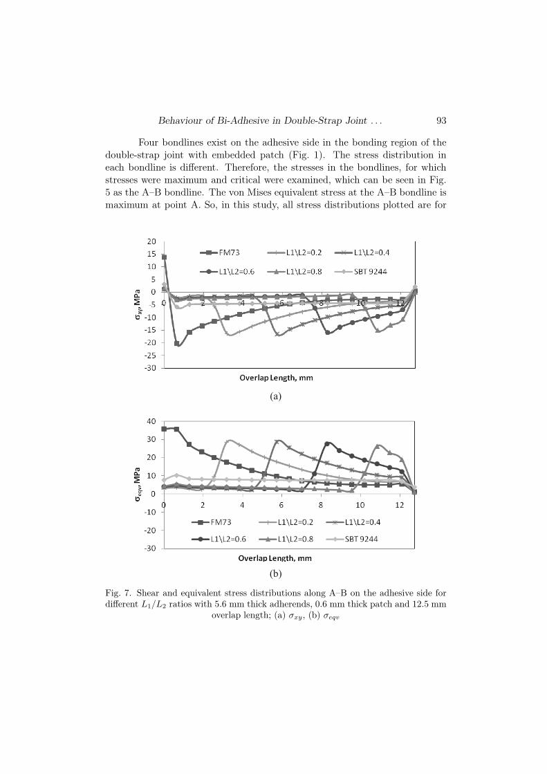
Four bondlines exist on the adhesive side in the bonding region of thedouble-strap joint with embedded patch (Fig. 1). The stress distribution ineach bondline is different. Therefore, the stresses in the bondlines, for whichstresses were maximum and critical were examined, which can be seen in Fig.5 as the A–B bondline. The von Mises equivalent stress at the A–B bondline ismaximum at point A. So, in this study, all stress distributions plotted are for
Fig. 7. Shear and equivalent stress distributions along A–B on the adhesive side fordifferent L1/L2 ratios with 5.6 mm thick adherends, 0.6 mm thick patch and 12.5 mm
overlap length; (a) σxy, (b) σeqv

94 Semsettin Temiz, Ismail Yasin Sulu, Hamit Adin
the A–B bondline.The longitudinal and peel stress distributions in the joint are given in
Fig. 6. The stresses in the joint with one adhesive alone (FM73 or SBT9244)are larger at point A. Stresses occurred at point A decrease by using the bi-adhesive. The reason for this is that SBT9244 adhesive is more flexible and loadtransfer capacity of a flexible adhesive is better due to its high strain to failure,which enables the applied load to be carried by a larger area of the overlap andthe joint to be stronger. Also, the flexible properties of SBT9244 contribute tostress relief at the ends of the overlap, reducing the stress concentrations [14].The stresses are close to zero, when moving away from point A. However, theincrease of stress occurs at the intersection of two adhesives (at L1/L2). Thisstress increase occurred at the intersection can be seen apparently in Fig. 7. Inthis figure, the shear and equivalent stress distributions are seen. The stressvalues are greater than the values of longitudinal and peel stresses.
4. Conclusion
In this work, the behaviour of bi-adhesive in double-strap joint with em-bedded patch is investigated by using finite element method. Our conclusionsare as follows:
– The increase ratio in failure loads due to using bi-adhesive variesbetween 9% and 56%.
– The maximum predicted failure loads of the joints with bi-adhesiveare at about L1/L2 = 0.2 − 0.6 length ratios.
– The increase ratio in failure load, due to using bi-adhesive, increaseswith increasing overlap length.
– The effect of the bi-adhesive on failure loads increases with increasein adherent thickness. The reason for the increase in failure load is that loadtransfer capacity of a flexible adhesive is better than hard adhesive, due to itshigh strain to failure, which enables the applied load to be carried by a largerarea of the overlap and the joint to be stronger. Also, the flexible properties ofelastic adhesive (SBT9244) contribute to stress relief at the ends of the overlap,reducing the stress concentrations.
R EFER EN CES
[1] Sabrina, F., M. Riadh, Z. Xiao-Ling. Experimental and Finite Element Anal-ysis of a Double Strap Joint between Steel Plates and Normal Modulus CFRP.Composite Structure, 75 (2006), 156–162.

Behaviour of Bi-Adhesive in Double-Strap Joint . . . 95
[2] Lee, H. K., S. H. Pyo, B. R. Kim. On Joint Strengths, Peel Stresses andFailure Modes in Adhesively bonded Double-strap supported Single-lap GFRPJoints. Composite Structure, 8 (2009), 44–54.
[3] Peter, C., R. Francis. Stress Analysis of Double-strap Bonded Joints using aVariational Method. Int. J. Adhesion Adhesives, 21 (2001), 241–247.
[4] Campilho, R. D. S. G., M. F. S. F. de Moura, D. A. Ramantani, J. J.
L. Morais, J. J. M. S. Domingues. Tensile Behaviour of Three-dimensionalCarbon-epoxy Adhesively Bonded Single- and Double-strap Repairs. Int. J. Ad-
hesion Adhesives, 29 (2009), 678–686.
[5] Jarry, E., R. A. Shenoi. Performance of Butt Strap Joints for Marine Appli-cations. Int. J. Adhesion Adhesives, 26 (2006), 162–176.
[6] Citil, S, S. Temiz, H. Altun, A. Ozel. Determination of Mechanical Proper-ties of Double-strap Adhesive Joints with an Embedded Patch. Journal Adhesion
Sci. Technol., 18 (2011), 2555–2567.
[7] Hart-Smith, L. J. Adhesive-bonded Single-lap Joints, NASA Technical ReportCR-112236, TX, Houston, NASA, 1973.
[8] Adams, R. D., J. Comyn, W. C. Wake. Structural Adhesive Joints in Engi-neering, Amsterdam, Elsevier, 1997.
[9] Adams, R. D., J. A. Harris. The Influence of Local Geometry on the Strengthof Adhesive Joints. Int. J. Adhesion Adhesives, 7 (1987), 69–80.
[10] Kinloch, A. J. Adhesion and Adhesives, London, Chapman and Hall, 1993.
[11] Al-Samhan, A., S. M. H. Darwish. Finite Element Modelling of WeldbondedJoints. Journal Mater. Proc. Technol., 142 (2003), 587–598.
[12] Tsai, M. Y., J. Morton. The effect of a Spew Fillet on Adhesive Stress Dis-tributions in Laminated Composite Single-lap Joints. Composite Structures, 32
(1995), 123–131.
[13] Apalak, M. K., R. Davies. Analysis and Design of Adhesively Bonded CornerJoints: Fillet Effect. International Journal Adhesion Adhesives, 14 (1994), 163–174.
[14] Temiz, S. Application of Bi-adhesive in Double-strap Joints subjected to BendingMoment. Journal of Adhesion Sci. Technol., 20 (2006), 1547–1560.
[15] Pires, I., L. Quintino, J. F. Durodola, A. Beevers. Performance of Bi-adhesive Bonded Aluminium Lap Joints. Int. J. Adhesion Adhesives, 23 (2003),215–223.
[16] Kumar, S., P. C. Pandey. Behaviour of Bi-adhesive Joints. Journal Adhesion
Sci. Technol., 24 (2010), 1251-1281.
[17] da Silva, L. F. M., C. Q. M. J. Lopes. Joint Strength Optimization by theMixed-adhesive Technique. Int. J. Adhesion Adhesives, 29 (2009), 509–514.
[18] das Neves, P. J. C., L. F. M. da Silva, R. D. Adams. Analysis of MixedAdhesive Bonded Joints Part II: Parametric Study. Journal of Adhesion Sci.
Technol., 23 (2009), 35–61.
[19] Marques, E. A. S., L. F. M. da Silva. Joint Strength Optimization of Adhe-sively Bonded Patch. Journal of Adhesion, 84 (2008), 915–934.

96 Semsettin Temiz, Ismail Yasin Sulu, Hamit Adin
[20] Ayd.in, M. D., A. Ozel, S. Temiz. Effect of Protrusion at the Ends of Bondline
in Single Lap Joints under Tension and Bending. J. Adhesion Sci. Technol., 18
(2004), 1589–1602.
[21] ANSYS. The General Purpose Finite Element Software, TX, Houston, SwansonAnalysis Systems, 2012.
[22] Adin, Hamit. The Investigation of the Effect of Angle on the Failure Load andStrength of Scarf Lap Joints. J. Applied Mathematical Modelling, 36 (2012), 2858.
[23] Adin, Hamit, D. M. Emin. Investigation of the Effect of Different Variableson Strength of Adhesive Joints. Mat.-wiss. U. Werkstofftech., 45 (2014), No. 10,869–878.
[24]..
Ozer, H.,..
Oz..
Ozkan. Three Dimensional Finite Element Analysis of Bi-adhesively Bonded Double Lap Joint. International Journal of Adhesion & Ad-
hesives, 37 (2012), 50–55.