Embed Size (px)
Citation preview

Available online at https://sej.journals.ekb.eg/
FACULTY OF ENGINEERING – SOHAG UNIVERSITY
SOHAG ENGINEERING JOURNAL (SEJ), VOL. 1, NO. 1, MARCH 2021
110
BEHAVIOR OF HYBRID STEEL/GFRP REINFORCED
COLUMNS UNDER LATERAL CYCLIC LOADING:
A NUMERICAL STUDY
Ahmed Arafaa*, Ata Elkareim Shoeibb, Sara Youssef Dandrawyb
aCivil Engineering Department, Faculty of Engineering, Sohag University, 82524, Sohag, Egypt bCivil Engineering Department, Faculty of Engineering, Helwan University, 11795, Cairo, Egypt
Abstract
This paper proposed hybrid (steel/glass fiber-reinforced polymer (GFRP) composites) bars as primary reinforcement for
modern reinforced concrete (RC) columns. A detailed two-dimensional finite element model (2D FEM), that considers
material and geometric nonlinearity and the bond behavior of steel and glass FRP (GFRP) reinforcement, was created, and
validated against the available experimental results. The built model predicted the experimentally obtained results
representing in failure mode and deformation response with good accuracy. Hybrid system that consists of steel/GFRP
combination was then studied. The results patently showed that hybrid reinforced columns can undergo large displacement
with minimal damage. This; however, can be guaranteed through carefully selection of reinforcement arrangement.
© 2021 Published by Faculty of Engineering – Sohag University. DOI: 10.21608/SEJ.2021.155958.
Keywords: Reinforced concrete; columns; simulated earthquake; hybrid; steel/GFRP.
1. INTRODUCTION
FRP reinforcement is currently being used as a viable alternative to steel in new concrete structures, especially
those in harsh environments [1]. Their noncorrodible nature, high strength, and light weight make them a
promising alternative to conventional steel reinforcement. Given their lower cost compared with other types of
FRP bars, glass-FRP (GFRP) bars have made their way into numerous cast-in-place bridge decks [3-7]. Recently,
concern has been triggered on the feasibility of using FRP-reinforced elements in seismic regions. This was due
to the limited ultimate strain and the elastic nature of FRP bars. To fill the gap of knowledge and give an answer
to these concerns, a pioneer experimental study conducted on the lateral response of a half-scale three-story
moment-resisting frame (MRF) reinforced completely with aramid FRP rebars and stirrups [8]. This was
followed with several studies [9 - 11] that included testing of different structural elements under reversed cyclic
loading. The results showed that FRP-reinforced elements exhibited stable linear behavior up to failure with a
low energy dissipation capacity and minimal damage. Recent application extended to the behavior of hybrid
steel/GFRP-reinforced concrete elements [12,13]. However, most of them are mainly focused either on columns
with steel bars as the main longitudinal and transverse reinforcement with adding GFRP bars to enhance the self-
centering ability, or frame elements that are governed by shear (for example, beam-columns connection). The
present study is a part of ongoing project that address the mentioned points through developing a hybrid system
* Corresponding author: [email protected]

Arafa et al: BEHAVIOR OF HYBRID STEEL/GFRP REINFORCED 111
in which the FRP represent the main reinforcement with added some steel bars to enhance the ductility and the
dissipation energy. This study will use nonlinear finite element analysis (FEA) as a powerful tool to verify this
expectation. A series of analyses will be first implemented on concrete columns reinforced with either steel or
GFRP bars to demonstrate that the finite element (FE) procedure can provide quick and reliable simulation. The
study is then extended to investigate the effect of using hybrid reinforcement through a comprehensive parametric
study. The discussion has been implemented in term of cracks pattern, failure mode, and energy dissipation.
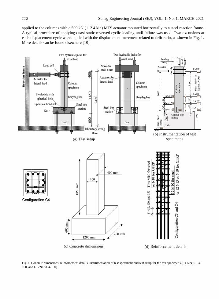
2. SUMMARY OF EXPERIMENTAL WORK
The FEM was developed and validated against well detailed columns slowly reinforced with steel; or GFRP
bars, which were experimentally studied by Elshamandy et al. [11]. The columns measured 400 × 400 × 1850
mm (15.7 × 15.7 × 72.8 in.) connected to a massive stub (1200 × 1200 × 600 mm [47.2 × 47.2 × 23.6 in.])
and cast vertically. The transverse load was applied at top of the specimen 1.65 m (65 in.) from the base of the
column with a displacement-controlled hydraulic actuator. The specimens represent a column 3.7 m (145.6 in.)
in height in a typical building with the assumed point of contraflexure located at column mid-height. Fig.1 shows
the concrete dimensions and reinforcement details. Fig.1 shows the GFRP cage reinforcement of the test
specimens. The axial load ratio (ALR) is defined as the index 𝑃/𝑓𝑐′𝐴𝑔, where 𝑃 is the constant axially applied
compression load, 𝑓𝑐′ is the concrete compressive strength, and 𝐴𝑔 is the gross cross- sectional area of the column.
ALR of 20% was chosen. For ease reference, the GFRP and steel-reinforced specimens were specified as
ST12N10-C4-100, and G12N13-C4-100, respectively.
All specimens were constructed with normal weight, ready mixed concrete having a target nominal
compressive strength 𝑓𝑐′ = 40 MPa (5.8 ksi). Table 1 lists the specimens’ details and gives the actual concrete
compressive strength based on the average values from tests performed on at least three 100 × 200 mm
(3.94 × 7.87 in.) cylinders for each concrete batch on the column’s day of testing. N10 and N8 grade 60 steel
bars were used in the steel-reinforced columns as longitudinal and transverse reinforcement, respectively. The
GFRP reinforcing bars in the GFRP-reinforced columns was Grade III sand-coated bars [32], N13 as longitudinal
bars and N10 as transverse reinforcement (rectilinear spirals and crossties). Table 2 shows the material properties
of the reinforcing bars.
TABLE 1. TEST SPECIMEN DETAILS
Specimen ID 𝑓𝑐′ 𝜌𝑙 (%)
Transverse reinforcement
𝑠 𝑃/𝑓𝑐′𝐴𝑔 𝐸𝐴
𝜌𝑣 (%) Ash act Ash req for drift
> 2.5% > 4%
ST12N10-C4-100 34 0.53 0.5 — — — 100 0.2 170
G12N13-C4-100 39 0.95 0.71 285.2 145.4 232.6 100 0.2 170
Notes: 𝑓𝑐′ is concrete compressive strength (MPa); 𝜌𝑙 is longitudinal reinforcement ratio; 𝜌𝑣 is
transverse reinforcement ratio; Ash act is actual provided transverse reinforcement (mm2); Ash req is
required transverse reinforcement according to Eq. (6) to achieve either 2.5% or 4% drift (mm2); 𝑠 is
spacing of transverse reinforcement (mm); 𝑃/𝑓𝑐′𝐴𝑔 is axial load level; 𝐸𝐴 is axial stiffness; E is
longitudinal bar modulus of elasticity; A is longitudinal bar area; 1 mm2 = 0.00155 in.2; 1 MPa =
145 psi; 1 kN = 0.225 kip.
Electrical strain gauges and linear variable differential transducers (LVDTs) were used to measure strain and
displacement, respectively, as shown in Fig. 1. Thirty electrical strain gauges were mounted on the longitudinal
and transverse reinforcement at three different levels above the stub. Concrete strain and curvature were
calculated using three sets of LVDTs that were placed in the column faces perpendicular to the loading direction
within the plastic hinge region. Four LVDTs were mounted to capture the lateral deformation at different column
heights. Two additional LVDTs were used to monitor the sliding at the column-stub connection and between the
stub and rigid floor. The axial load was applied at the top of the column, where the axial stress was maintained
constant throughout the test Fig. 1. Cyclic lateral displacements at a rate of 1.3 mm/min (0.05 in./min) were
112 Sohag Engineering Journal (SEJ), VOL. 1, No. 1, MARCH 2021
applied to the columns with a 500 kN (112.4 kip) MTS actuator mounted horizontally to a steel reaction frame.
A typical procedure of applying quasi-static reversed cyclic loading until failure was used. Two excursions at
each displacement cycle were applied with the displacement increment related to drift ratio, as shown in Fig. 1.
More details can be found elsewhere [10].
Fig. 1. Concrete dimensions, reinforcement details, Instrumentation of test specimens and test setup for the test specimens (ST12N10-C4-
100, and G12N13-C4-100)
(d) Reinforcement details (c) Concrete dimensions
(a) Test setup
(b) Instrumentation of test
specimens

Arafa et al: BEHAVIOR OF HYBRID STEEL/GFRP REINFORCED 113
TABLE 2. TENSILE PROPERTIES OF THE REINFORCEMENT.
Bar* 𝑑𝑏, mm 𝐴𝑓, mm2 𝐸𝑓, GPa f †, MPa
fu 𝜀𝑓𝑢, %
Straight bars
9.5 71.3 200 𝑓𝑦 = 420 𝜀𝑦 = 0.2 9.5
12.7 126.7 69.6 1392 2.00 12.7
Bent GFRP N10 (No. 3) rectilinear spiral and crossties
Straight 9.5 71.3 52 962 1.85
*Numbers in parentheses are manufacturer’s bar designation.
3. FINITE ELEMENT ANALYSIS AND VALIDATION
Numerical analyses were implemented in this study with VecTor2 specialized finite element (FE) software
[14]. The program is a two-dimensional FE simulation tool based on a secant– stiffness formulation using a total
load, iterative procedure, which employs constitutive relations for concrete and reinforcement based on the
modified compression field theory (MCFT) [15]. The MCFT is a powerful analytical model that predicts the
load–deformation response of RC elements that are subjected to in-plane shear and normal stresses. The theory
is based on a smeared crack approach in which the cracked concrete is treated as a new material with unique
stress–strain characteristics. Equilibrium, compatibility, and material stress–strain relationships are considered
to represent average stresses and average strains, in addition to local stresses at crack positions. More details
about the program can be found in the user manual [14].
3.1. Model geometry and meshing
Four-node quadrilateral elements were used to model the concrete and the longitudinal and horizontal bars
were simulated with truss elements. A representative FE mesh and set of truss elements was used in the analysis
Fig. 2. To eliminate the localization effect, the elements’ aspect ratios were <1.5, as recommended by Palermo
and Vecchio [16]. The convergence criteria were examined based on iterative simulations of different meshes
with different numbers of column elements. The hysteretic response, failure mode, and strain readings were
examined for the simulated columns with different mesh sizes and compared with the experimental results of the
tested columns. The mesh size was then chosen that had no additional effect of refined mesh on the numerical
results, which considered no localization effect.
3.2. Material modeling
VecTor2 provides useful features when modeling RC elements: (1) a comprehensive nonlinear constitutive
model of concrete, (2) implementation of the effect of cracks on the behavior of RC, (3) inclusion of the effect
of tension stiffening and compressive strength reduction due to cracks, and (4) implementation of a user defined
bond–stress relationship between reinforcement and concrete. The following section discusses the constitutive
models for the concrete and the steel and GFRP bars.
3.2.1. Concrete
Fig. 3 illustrates the constitutive models used in modeling concrete. The Hognestad parabola [17] and a
modified Kent-Park formulation [18], which were intended primarily for the analysis of RC structures subjected
to cyclic and dynamic loads, were used to model the pre and post-peak response of the concrete. These models
were broadly used in several investigations to model structural columns and showed an accurate simulation of
the behavior [16], [19-22]. The hysteric response of concrete was modeled based on Palermo and Vecchio [23].
This model was adopted in this study, since it explicitly considers concrete damage caused by shear deformations.
In addition, the model was formulated to provide substantial compatibility with nonlinear FEA in the context of

114 Sohag Engineering Journal (SEJ), VOL. 1, No. 1, MARCH 2021
Fig. 2. Typical FE meshing.
smeared rotating cracks in both the compression and tension stress regimes. The concrete confinement provided
by the closed stirrups was considered using Kupfer model [24]. The model was established for steel-reinforced
elements. To make this model suitable for elements reinforced with GFRP bars and stirrups, which have lower
moduli of elasticity than steel reinforcement, an equivalent area of GFRP stirrups was used as recommended in
[25].
The equivalent area was defined as the area of a steel bar that produced the same stiffness as the actual GFRP
bars. Compression softening was simulated using the Vecchio model [15], which considers the reduction in
compressive strength and stiffness caused by coexisting transverse cracking and tensile straining. This model
was adopted because it considers the softening of both strength and strain. The modified Bentz model [34] was
used to model the tension stiffening effects. This model accounts for the tensile stresses in concrete between
cracks induced by the bond action between the reinforcement and concrete. The model was formulated to account
for the bond characteristics of the reinforcement, and therefore, the influence extends into surrounding elements
that do not contain any reinforcement. Tension softening was modeled with a linear descending branch after
cracking. The dilation of concrete, which represents the lateral expansion of concrete due to internal micro-
cracking and increases as the compressive stresses increase, was modeled with the variable Poisson’s ratio that
was proposed by Kupfer and Gerstle [26]. The constitutive models used to simulate the tension stiffening effects,
the tension softening, and the dilation of concrete were adopted based on the previous numerical simulations for
GFRP-reinforced walls [27].
3.2.2. Reinforcement material
Fig. 3 illustrates the constitutive models used to model the steel and GFRP bars. The hysteretic behavior of
the steel bars was modeled according to Seckin [28]. This model was selected because it considers the
Bauschinger effect beyond the yielding of steel and the associated softening of both strength and strain. However,
the stress–strain curve was set to linear for the GFRP bars with a modulus of elasticity equal to the elastic modulus
16
50
mm
Arafa et al: BEHAVIOR OF HYBRID STEEL/GFRP REINFORCED 115
of the GFRP reinforcement. The dowel action of the steel bars was represented with the Tassios model [29] and
the dowel action was neglected for the GFRP bars, according to ACI 440.1R [1]. VecTor2 provides the option to
define the bond–slip relationship between reinforcing bars and the surrounding concrete. Based on the findings
of an experimental investigation by Vint [30] on the bond–slip behavior between sand-coated GFRP bars and
concrete, the modified Bertero-Eligehausen model [31] was adopted to simulate the bond between GFRP bars
and concrete. A complete bond was used between steel bars and concrete, which has been reported as being
reliable when modeling steel-reinforced columns.
Nodes at the base of the simulated column were fixed against movement in both the horizontal and vertical
directions. The lateral displacement was applied at a height of 1650 mm from the base.
Fig. 3. The used constitutive models: (a) concrete hysteretic response (data from Palermo and Vecchio [16]); (b) concrete pre- and post-peak
response (data from Hognestad [17] and Scott et al. [18]); (c) steel reinforcement hysteretic (data from Seckin [28]); and (d) FRP
reinforcement hysteretic response.
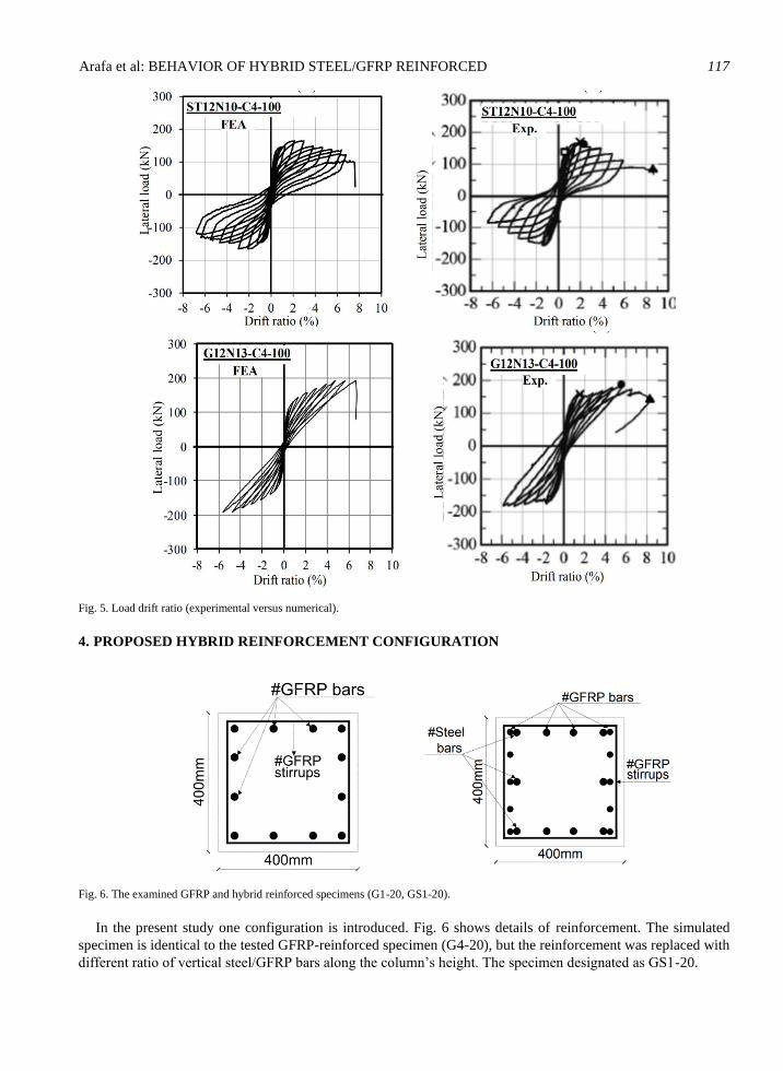
3.2.3. Model validation
Fig. 4 shows a comparison between the experimentally monitored and analytically predicted cracks pattern
and failure modes of the column’s specimens, in addition to the principal stress contours of the simulated
columns. Generally, the simulated columns exhibited similar crack patterns to those captured from the experiment
in term of crack inclination, tendency, and propagation. Fig. 5 also compares the predicted load-displacement
hysteretic response to the companion experimentally obtained. Clearly, the model could predict the specimen’s

116 Sohag Engineering Journal (SEJ), VOL. 1, No. 1, MARCH 2021
first flexure crack, ultimate strength, and energy dissipation with good accuracy; the difference within 10%.
Based on the validation results, it can be concluded that the developed FEM can be extended to assessment the
effect of using hybrid reinforcement.
Fig. 4. FEA versus experimental results.
FEA Exp.
G12N13-C4-100
Failure
mode Failure
mode
ST12N10-C4-100
Failure
mode Failure mode
FEA Exp.
Arafa et al: BEHAVIOR OF HYBRID STEEL/GFRP REINFORCED 117
Fig. 5. Load drift ratio (experimental versus numerical).
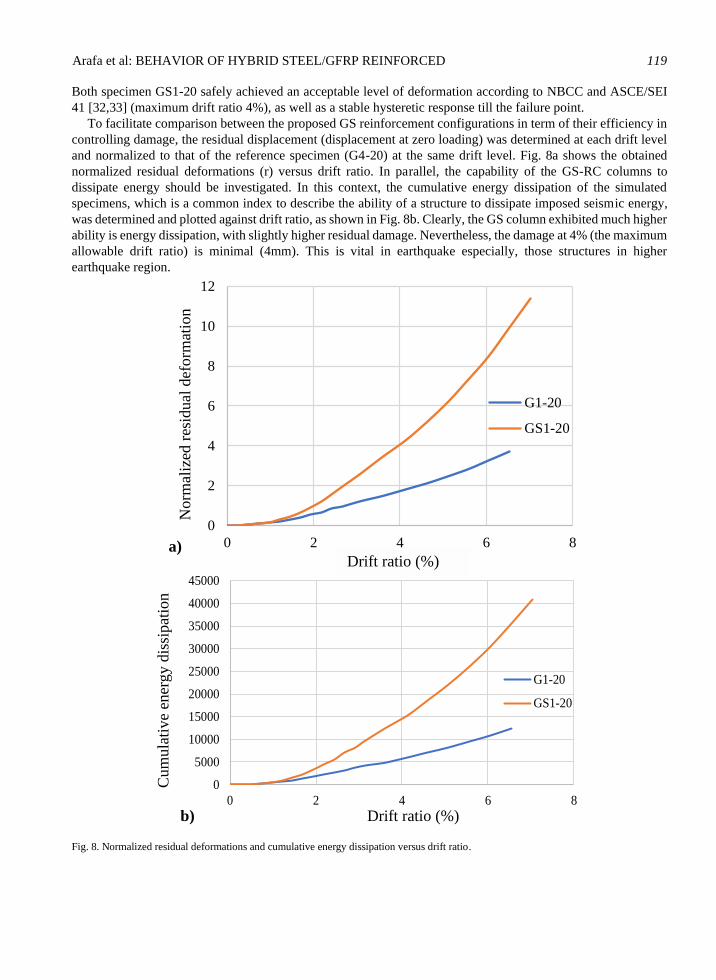
4. PROPOSED HYBRID REINFORCEMENT CONFIGURATION
Fig. 6. The examined GFRP and hybrid reinforced specimens (G1-20, GS1-20).
In the present study one configuration is introduced. Fig. 6 shows details of reinforcement. The simulated
specimen is identical to the tested GFRP-reinforced specimen (G4-20), but the reinforcement was replaced with
different ratio of vertical steel/GFRP bars along the column’s height. The specimen designated as GS1-20.

118 Sohag Engineering Journal (SEJ), VOL. 1, No. 1, MARCH 2021
5. ANALYSIS RESULTS AND DISCUSSION
Fig. 7. Failure mode and lateral load-drift ratio hysteretic response (G1-20 and GS1-20).
Fig. 7 shows the cracks pattern and failure modes of G1-20 and GS1-20. The specimens initially exhibited a
stiff behavior. The specimens exhibited initial stiff behavior without cracking. With more loading, the flexural
cracks initiated at the column bottom associated significant reduction in the lateral stiffness. With further loading,
cover splitting gradually initiated at the most compressed fibers of the columns associated with gradual spalling
of the concrete cover. This was recorded from the measured concrete compressive strain that attained 0.0035 at
the lower part of the columns and began to spread higher and higher. At this stage, the longitudinal steel bars in
GS RC column yielded. Nevertheless, the specimen continued to carry loading without strength degradation.
Ultimately, the specimens exhibited ruptures of bars at the most tensile fiber with abrupt strength degradation. It
is clear from Fig. 7 that meshes at tension zone have noticeable vertical deformation that implies bars rupture.
Bar rupture
GS1-20 G1-20
Bar rupture
Arafa et al: BEHAVIOR OF HYBRID STEEL/GFRP REINFORCED 119
Both specimen GS1-20 safely achieved an acceptable level of deformation according to NBCC and ASCE/SEI
41 [32,33] (maximum drift ratio 4%), as well as a stable hysteretic response till the failure point.
To facilitate comparison between the proposed GS reinforcement configurations in term of their efficiency in
controlling damage, the residual displacement (displacement at zero loading) was determined at each drift level
and normalized to that of the reference specimen (G4-20) at the same drift level. Fig. 8a shows the obtained
normalized residual deformations (r) versus drift ratio. In parallel, the capability of the GS-RC columns to
dissipate energy should be investigated. In this context, the cumulative energy dissipation of the simulated
specimens, which is a common index to describe the ability of a structure to dissipate imposed seismic energy,
was determined and plotted against drift ratio, as shown in Fig. 8b. Clearly, the GS column exhibited much higher
ability is energy dissipation, with slightly higher residual damage. Nevertheless, the damage at 4% (the maximum
allowable drift ratio) is minimal (4mm). This is vital in earthquake especially, those structures in higher
earthquake region.
Fig. 8. Normalized residual deformations and cumulative energy dissipation versus drift ratio.
Drift ratio (%)
Drift ratio (%)
Norm
aliz
ed r
esid
ual
def
orm
atio
n
(r)
Cum
ula
tive
ener
gy d
issi
pat
ion
(E)
a)
b)
0
2
4
6
8
10
12
0 2 4 6 8
G1-20
GS1-20
0
5000
10000
15000
20000
25000
30000
35000
40000
45000
0 2 4 6 8
G1-20
GS1-20
120 Sohag Engineering Journal (SEJ), VOL. 1, No. 1, MARCH 2021
6. CONCLUSION
This paper presents a numerical investigation using program (Vector 2) a two-dimensional finite element
which conducted to simulate the reversed cyclic behavior of hybrid (steel/GFRP) reinforced concrete columns.
Based on the results and the presented discussion, the following conclusions can be drawn:
1. The proposed model accurately predicted the behavior of both the steel and GFRP-reinforced concrete
columns available in the literature.
2. The lateral response of hybrid steel/GFRP-reinforced concrete columns supports the feasibility of using the
hybrid reinforcement concept as a simple control-damage tool to achieve the required seismic performance.
3. More studies are needed to provide design guidelines that can be incorporated into the next seismic design
codes editions.
REFERENCES
[1] American Concrete Institute (ACI). “Guide for the Design and Construction of Structural Concrete Reinforced with Fiber-Reinforced Polymer (FRP) Bars.” ACI 440.1R-15, 2015 Farmington Hills,MI.
[2] Canadian Standards Association (CAN/CSA). Design and Construction of Building Components with Fiber-Reinforced Polymers (S806-12). Mississauga, (ON, Canada): CSA; 2012, pp. 208.
[3] T. E. Bradberry, “Concrete bridge decks reinforced with fiber-reinforced polymer bars,” Transportation Research Record, Vol. 1770, no. 1, pp. 94-104, 2001.
[4] A. Nanni, , and S. Faza, “Design and construction of concrete reinforced with FRP bars: An emerging technology,” Concr. Int, Vol. 24, pp. 53-58, 2002.
[5] E. El-Salakawy, B. Benmokrane, A. El-Ragaby and D. Nadeau, “Field investigation on the first bridge deck slab reinforced with glass FRP bars constructed in Canada, ” Journal of composites for construction, vol. 9, no. 6, pp. 470-479, 2005.
[6] B. Benmokrane, E. El-Salakawy, A. El-Ragaby and S. El-Gamal, “Performance evaluation of innovative concrete bridge deck slabs reinforced with fibre-reinforced-polymer bars, ” Canadian Journal of Civil Engineering, vol. 34, no. 3, pp. 298-310, 2007.
[7] A. Ehab, F. Settecasi, and B. Benmokrane. “Construction and testing of GFRP steel hybrid-reinforced concrete bridge-deck slabs of sainte-catherine overpass bridges,” Journal of Bridge Engineering, vol. 19, no. 6, pp. 0401401, 2014.
[8] H. Fukuyama, Y. Masuda, Y. Sonobe, M. Tanigaki “Structural performances of concrete frame reinforced with FRP reinforcement,” In: 2nd international RILEM Symposium, Non-Metallic (FRP) Reinforcement for Concrete Structures. Ghent, Belgium: Chapman & Hall;p. 275–86, 1995.
[9] M. Hasaballa and E. El-Salakawy, “Shear capacity of exterior beam-column joints reinforced with GFRP bars and stirrups, ” J. Compos. Constr., vol. 20, no. 2, pp. 04015047, 2016.
[10] S. K. Ghomi and E. El-Salakawy,” Seismic performance of GFRP-RC exterior beam-column joints with lateral beams”. J Compos Constr, vol. 20, pp. 04015019, 2016.
[11] M. G. El-shamandy, A. S. Farghaly, and B. Benmokrane, “Experimental behavior of glass fiber-reinforced polymer- reinforced concrete columns under lateral cyclic load,” ACI Structural Journal, vol. 115, no. 2, pp. 337-349, 2018.
[12] M. L. Nehdi and A. M. Said, “Behaviour of RC beam-column joints with hybrid reinforcement under simulated earthquake loading,” 7th International Conference on Multipurpose High-Rise Towers and Tall Buildings, 2005.
[13] H. A. Ibrahim, M. F. M. Fahmy, and Wu. Zhishen, “Numerical study of steel-to-FRP reinforcement ratio as a design-tool controlling the lateral response of SFRC beam-column joints,” Engineering Structures, vol. 172, pp. 253-274, 2018.
[14] P. S. Wong and FJ. Vecchio ,”VecTor 2 & formworks user’s manuals”, Toronto, ON, Canada: Department of Civil Engineering, University of Toronto; 2002, p. 213.
[15] F. J. Vecchio and M. P. Collins, ” Compression response of cracked reinforced concrete,” Journal of structural engineering, vol. 119, no. 12, pp. 3590-3610, 1993.
[16] D. Palermo and F. J. Vecchio, "Simulation of cyclically loaded concrete structures based on the finite-element method," Journal of Structural Engineering , vol. 133, no. 5, pp. 728-738, 2007.
[17] Hognestad and Eivind, “Study of combined bending and axial load in reinforced concrete members,” University of Illinois at Urbana Champaign, College of Engineering. Engineering Experiment Station, 1951.
[18] B. D. Scott, R. Park and M. J. N. Priestley, “Stress-strain behavior of concrete confined by overlapping hoops at low and high strain rates,” J. ACI Struct., vol. 79, no. 1, pp. 13–27,1982.
[19] C. K. Gulec and A. S. Whittaker,” Performance-based assessment and design of squat reinforced concrete shear walls,” pp. 09_0010, Buffalo, NY: MCEER, 2009.
[20] S. Ghazizadeh, C. A. Cruz-Noguez, and F. Talaei, “Analytical model for hybrid FRP-steel reinforced shear walls,” Engineering Structures, vol. 156, pp. 556-566, 2018.
[21] F. J. Vecchio, , and I. McQuade, “ Towards improved modeling of steel-concrete composite wall elements,” Nuclear engineering and design, vol. 241, no. 8, pp. 2629-2642, 2011.

Arafa et al: BEHAVIOR OF HYBRID STEEL/GFRP REINFORCED 121
[22] N. Mohamed, A. S. Farghaly, B. Benmokrane and K. W. Neale , “Numerical simulation of mid-rise concrete shear walls
reinforced with GFRP bars subjected to lateral displacement reversals,” Engineering structures, vol. 73, pp. 62-71, 2014.
[23] D. Palermo, F. J. Vecchio and H. Solanki, “ Behavior of three-dimensional reinforced concrete shear walls,” ACI Structural Journal, vol. 99, no. 1, pp. 81-89, 2002.
[24] H. Kupfer , H. K. Hilsdorf, and H. Rusch, “Behavior of concrete under biaxial stresses,” Journal proceedings. Vol. 66, No. 8., pp. 656-666, 1969.
[25] S. K. Ghomi and E. El-Salakawy, “Seismic behavior of exterior GFRP-RC beam–column connections: Analytical study,” Journal of Composites for Construction, vol. 22, no. 4, pp. 04018022 2018.
[26] H. Kupfer, B. Helmut, and K. H. Gerstle. "Behavior of concrete under biaxial stresses," Journal of the engineering mechanics division, vol. 99, no. 4, pp. 853-866, 1973.
[27] N. Mohamed, A. S. Farghaly, B. Benmokrane and K. W. Neale, “ Flexure and shear deformation of GFRP-reinforced shear walls,” Journal of Composites for Construction, vol. 18, no. 2, pp. 04013044, 2014.
[28] M. Seckin, “ Hysteretic behavior of cast-in-place exterior beam column sub-assemblies,” pp. 4139-4139, 1982.
[29] X. G. He, and A. K. H. Kwan, “ Modeling dowel action of reinforcement bars for finite element analysis of concrete structures,” Computers & Structures, vol. 79, no. 6, pp.595-604, 2001.
[30] L. Vint,” Investigation of bond properties of glass fibre reinforced polymer (GFRP) bars in concrete under direct tension,” Diss. 2012.
[31] R. Eligehausen, E. P. Popov, and V. V. Bertero, “Local bond stress-slip relationships of deformed bars under generalized excitations,” 1982.
[32] CAN/CSA S807-15, “Specification for Fibre Reinforced Poly-mers,” Canadian Standards Association, Mississauga, ON, Canada, 2015, p. 44.
[33] P. Ricci, G. M. Verderame, and G. Manfredi, “ASCE/SEI 41 provisions on deformation capacity of older-type reinforced concrete columns with plain bars," Journal of Structural Engineering, vol. 139, no. 12, p. 04013014, 2013.
[34] E. C. Bentz,. "Sectional Analysis of Reinforced Concrete Members", Ph.D. Thesis, Department of Civil Engineering, University of Toronto, p. 310, 2000.