Embed Size (px)
Citation preview
577577577577577
SP-228—38
Behavior of GeopolymerBehavior of GeopolymerBehavior of GeopolymerBehavior of GeopolymerBehavior of GeopolymerCCCCConconconconconcrrrrretetetetete Ce Ce Ce Ce Cooooolumnlumnlumnlumnlumnsssss u u u u under Ender Ender Ender Ender Equalqualqualqualqual
LLLLLoooooaaaaad Ed Ed Ed Ed Eccccccccccentricentricentricentricentricitieitieitieitieitiesssss
bbbbbyyyyy D D D D D.M.J. .M.J. .M.J. .M.J. .M.J. SSSSSumumumumumajajajajajouououououwwwww, D, D, D, D, D. Har. Har. Har. Har. Hardjitdjitdjitdjitdjitooooo, , , , , S. S. S. S. S. WWWWWalalalalallllllah,ah,ah,ah,ah,and B.and B.and B.and B.and B.VVVVV. R. R. R. R. Rananananangggggananananan
Keywords: column; concrete; deflection; eccentricity; geopolymer;reinforcement; strength
Synopsis: In geopolymer concrete, a by-product material rich in silicon and aluminium (low calcium fly ash) is chemically activated by a high alkaline solution to form a paste that binds the loose coarse and fine aggregates, as well as other un-reacted materials in the mixture. This paper presents the results of an experimental study on the behaviour and the strength of twelve geopolymer concrete slender columns under equal load eccentricities. The primary variables of the test series were concrete compressive strength, longitudinal reinforcement ratio, and load eccentricity. The test results gathered included the deflection and the load capacity of the columns. The test failure loads were compared with the values calculated by the methods currently available for Ordinary Portland Cement (OPC) concrete. Excellent correlation between experimental and analytical results is found.
578578578578578 Sumajouw et al.Sumajouw et al.Sumajouw et al.Sumajouw et al.Sumajouw et al.
Dody M.J. Sumajouw is a lecturer at Sam Ratulangi University, Manado, Indonesia, and currently a Ph.D student in the Civil Engineering Department, Curtin University of Technology, Perth, Australia. Djwantoro Hardjito is a lecturer at Widya Mandira Catholic University, Kupang, Indonesia, and currently a Ph.D student in the Civil Engineering Department, Curtin University of Technology, Perth, Australia. Steenie E. Wallah is a lecturer at Sam Ratulangi University, Manado, Indonesia, and currently a Ph.D student in the Civil Engineering Department, Curtin University of Technology, Perth, Australia.
ACI Fellow B. Vijaya Rangan is Professor of Civil Engineering in the Faculty of Engineering and Computing, Curtin University of Technology, Perth, Australia. He was a recipient of numerous awards, including ACI’s Raymond C. Reese Structural Research Award.
INTRODUCTION
Concrete, a conglomerate of Ordinary Portland Cement (OPC), coarse aggregate, sand and water, is widely used in the construction of many infrastructures such as bridges, highways, dams, and urban facilities. The increasing worldwide production of OPC indicates that concrete will continue to be a chosen material of construction in the future (1). However, the production of OPC not only consumes significant amount of natural resources and energy but also releases substantial quantity of carbon dioxide (CO2) to the atmosphere (2). Currently, the cement industries produce 1.5 billion tons of OPC each year. This adds about 1.5 billion tons of CO2 into the atmosphere (3, 4, 5).
One of the efforts to produce more environmentally friendly concrete is to replace the
amount of OPC in concrete with by-product materials such as fly ash (2). An important achievement in this regard is the development of high volume fly ash (HVFA) concrete that utilizes about 40 percent of OPC, and yet possesses excellent mechanical properties with enhanced durability performance. The test results show that HVFA concrete is more durable than OPC concrete (4). Another effort to make environmentally friendly concrete is the development of inorganic alumino-silicate polymer, called Geopolymer, synthesized from materials of geological origin or by-product materials such as fly ash that are rich in silicon and aluminium (6).
High-High-High-High-High-StrStrStrStrStrenenenenengggggth/High-Pth/High-Pth/High-Pth/High-Pth/High-Perererererffffformormormormormancancancancance Ce Ce Ce Ce Conconconconconcrrrrreteteteteteeeee 579579579579579
Fly ash, one of the source materials for geopolymer binders, is available abundantly world wide, but to date its utilization is limited. From 1998 estimation, the global coal ash production was more than 390 million tons annually, but its utilization was less than 15% (1). In the USA, the annual production of fly ash is approximately 63 million tons, and only 18 to 20% of that total is used by the concrete industries (7).
In the future, fly ash production will increase, especially in countries such as China and India. Just from these two countries, it is estimated that by the year 2010 the production of the fly ash will be 780 million tones annually (4). Accordingly, efforts to utilize this by-product material in concrete manufacture are important to make concrete more environmentally friendly. For instance, every million tons of fly ash that replaces OPC helps to conserve one million tons of lime stone, 0.25 million ton of coal and over 80 million units of power; not withstanding the abatement of 1.5 million tons of CO2 to atmosphere (8).
The previous research on geopolymer concrete mainly concerned with studies of the
short-term and long-term properties. Hardjito et al. (9, 10, 11) investigated the engineering properties including the various salient parameters that influence the compressive strength of geopolymer concrete. Wallah et al. (12, 13) investigated the creep, shrinkage, and effect of sulfate attack on geopolymer concrete. It was found that geopolymer concrete possesses high compressive strength, undergoes very little drying shrinkage and moderately low creep, and shows excellent resistance to sulfate attack.
RESEARCH SIGNIFICANCE
This paper deals with the research on geopolymer concrete columns. The research comprised both experimental and analytical studies. The experimental work involved tests on twelve geopolymer concrete columns. The primary variables of the experimental work were longitudinal reinforcement ratio, load eccentricity, and compressive strength of concrete. The analytical work involved methods currently used for OPC concrete columns. A simplified stability analysis proposed earlier by Rangan (14) was used to calculate the strength of columns. In addition, the design provisions contained in Section 10.12 of ACI 318-02 (15) were used to evaluate the strength of geopolymer concrete columns.
GEOPOLYMERS
The term geopolymer was first introduced by Davidovits (6) to describe mineral binders resulting from geochemistry. The chemical composition of this material is similar to zeolite, but amorphous in microstructure. In geopolymers, the silica and alumina present in the source materials are induced by alkaline activators to produce binders. The chemical
580580580580580 Sumajouw et al.Sumajouw et al.Sumajouw et al.Sumajouw et al.Sumajouw et al.
process involved in the formation of geopolymer binders is completely different to that of OPC paste. The chemical reaction period is fast, and the required curing period is within 8 to 24 hours.
Most of the literature available on this material deals with geopolymer pastes. These
studies show that geopolymer binders are durable and strong (16). Davidovits and Sawyer (17) used grounded blast furnace slag to produce geopolymer binders. These binders were used as supplementary cementing materials in the production of precast concrete products. Balaguru et al. (18) used geopolymers to replace organic polymers as adhesives in strengthening structural members. The materials were found to be fire resistant and durable under UV light. Van Jaarsveld et al. (19) carried out experiments on geopolymers using two types of fly ash. They found that the compressive strength after 14 days was in the range of 5 to 51 MPa. Palomo et al. (20) studied the influence of curing temperature, curing time and activator solution-to-fly ash ratio on the compressive strength. Compressive strength up to 60 MPa was obtained for curing at 85oC for 5 hours. Swanepoel and Strydom (21) conducted a study on geopolymers produced by mixing fly ash, kaolinite, sodium silicate solution, sodium hydroxide and water. Both the curing time and the curing temperature affected the compressive strength. Van Jaarsveld et al. (22) studied the interrelationship of various parameters that affected the properties of fly ash-based geopolymers.
A research program to study the engineering properties and application of fly ash based
geopolymer concrete is in progress at Curtin University of Technology, Perth, Australia. The program, started in 2001, involves geopolymer concrete mix design, the short-term properties, the long-term properties such as shrinkage, creep, and exposure to sulfate attack, and the behaviour and the strength of structural elements such as columns and beams.
GEOPOLYMER CONCRETE
In the authors’ experimental work, geopolymer is used as the binder, instead of cement paste, to produce concrete. The geopolymer paste binds the loose coarse aggregates, fine aggregates and other un-reacted materials together to form the geopolymer concrete. The manufacturing of geopolymer concrete is carried out using the usual concrete technology methods.
As in the OPC concrete, the aggregates occupy the largest volume, i.e. about 75-80% by mass, in geopolymer concrete. The silicon and the aluminum in the fly ash are activated by a combination of sodium hydroxide and sodium silicate solutions to form the geopolymer paste that binds the loose aggregates and other un-reacted materials to yield the geopolymer concrete.
High-High-High-High-High-StrStrStrStrStrenenenenengggggth/High-Pth/High-Pth/High-Pth/High-Pth/High-Perererererffffformormormormormancancancancance Ce Ce Ce Ce Conconconconconcrrrrreteteteteteeeee 581581581581581
EXPERIMENTAL PROGRAMME
Materials
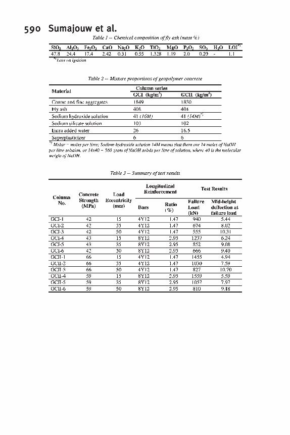
The technology to make geopolymer concrete used in this study was based on the authors’ earlier work (9, 10, 11). Low calcium (class F) fly ash obtained from a local power plant was used as the base material. The chemical composition of the fly ash determined by X-ray Fluorescence (XRF) analysis is given in Table 1. Analytical grade sodium hydroxide (NaOH) in flake form with 98% purity was used.
To avoid contamination with unknown substances in the mixing water, distilled water
was used to dissolve the NaOH flakes to produce a solution with a concentration of 16 or 14 Molars (molar = moles per litre). The Sodium silicate solution (Na2O=14.7%, SiO2=29.4% and water=55.9% by mass) was mixed with NaOH solution to produce the alkaline activator solution.
Three types of locally available aggregates comprising 10mm and 7mm coarse
aggregates, and fine sand were used. The fineness modulus of combined aggregates was 4.50.
Deformed bars (N500 grade) were used as steel reinforcement. Test on samples of the
longitudinal steel of size N12 (area = 110mm2) resulted in an average yield strength of 519 MPa, and the ultimate strength was 665 MPa. The lateral reinforcement (6mm diameter wires) had average yield strength of about 570 MPa.
A commercially available naphthalane based Superplasticizer was used to improve the
workability.
Mixture proportions
The mixture proportions of geopolymer concrete used in this study are given in Table 2. The mixtures were designed to achieve an average compressive strength of 40 MPa for GCI and 60 MPa for GCII. Column geometry and reinforcement configuration
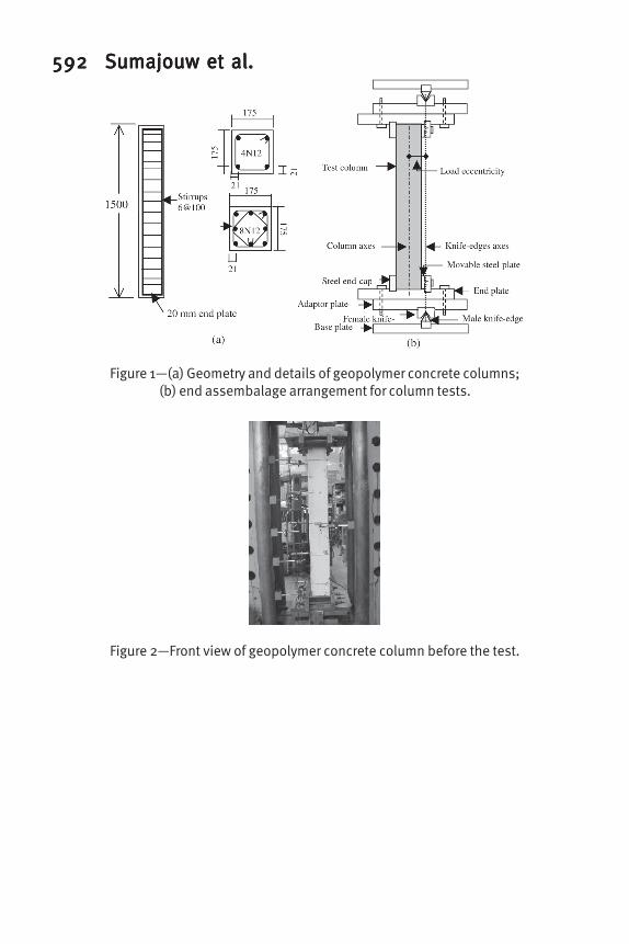
Twelve geopolymer concrete columns were made and tested. The column cross section was a 175mm square. The height of the columns was 1500mm. Due to the use of end assemblages at both ends of test columns, the effective length of the columns measured between centre-to-centre of the load knife-edges was 1684mm. Six columns contained four 12mm (N 12) deformed bars, and the other six were reinforced with eight 12mm deformed bars (N 12) as longitudinal reinforcement. These arrangements gave reinforcement ratios of 1.47% and 2.95% respectively. Wires of 6mm diameter were used as lateral reinforcement
582582582582582 Sumajouw et al.Sumajouw et al.Sumajouw et al.Sumajouw et al.Sumajouw et al.
(Figure 1). A concrete cover of 15mm was provided between the longitudinal bars and all faces of the column. The column cross-sections are shown in Figure 1. The column details are given in Table 3. Manufacture and curing process
The coarse aggregates and sand were in saturated surface dry condition. The aggregates and the dry fly ash were first mixed in a pan mixer for about three minutes. While mixing, the alkaline solution and the extra water were mixed together and added to the solid particles. The mixing of the wet mixture continued for another four minutes. The fresh concrete was cast into the molds immediately after mixing. All columns were cast horizontally in wooden molds in three layers. Each layer was manually compacted using a rod bar, and then vibrated for 30 seconds on a vibrating table. With each mixture, a number of 100mm diameter by 200mm high cylinders were also cast. The average measured slump of fresh concrete was 240mm for series GCI and 220mm for series GCII.
Immediately after casting, the GC-I column series and the cylinders were cured in a
steam-curing chamber at a temperature of 60oC for 24 hours. The specimens of GC-II series were kept in the room temperature for three days and then cured in the steam-curing chamber at a temperature of 60oC for 24 hours. In order to maintain the temperature inside the chamber, the solenoid valve complete with digital temperature controller and thermocouple were attached to the boiler installation system. The digital controller automatically opened the solenoid valve to deliver the steam, and closed after desired temperature inside the chamber was reached. To avoid condensation over the concrete, a sheet of plastic was used to cover the concrete surface.
After curing, the columns and the cylinders were removed from the chamber and left to
air dry at room temperature for another 24 hours before demoulding. The test specimens were then left in the laboratory ambient conditions until the day of testing. The laboratory temperature varied between 25o and 35oC during that period.
TEST OF SPECIMENS
Test set up and instrumentation
All columns were tested in a Universal test machine with a capacity of 2500 kN. Two specially built end assemblages were used at the ends of the columns (Figure 1b). The end assemblages were designed to accurately position the column to the specified load eccentricity at all stages of loading during testing. Each of the end assemblage consisted of three 40mm thick plates. The end assemblages were attached to the test machine by rigidly bolted base plates at the top and bottom platens of the machine. The base plates had a male knife-edge that was fitted to female knife-edge slotted into an adaptor plate. The tips of the
High-High-High-High-High-StrStrStrStrStrenenenenengggggth/High-Pth/High-Pth/High-Pth/High-Pth/High-Perererererffffformormormormormancancancancance Ce Ce Ce Ce Conconconconconcrrrrreteteteteteeeee 583583583583583
knife-edges were smooth and curved in shape in order to minimize friction between them. The adaptor plate had a number of holes to accommodate different load eccentricity ranging from 0 to 65mm with 5mm intervals. This arrangement simulated an ideal hinge support condition, and has been successfully used in previous column tests (23, 25, 26). The steel end caps attached at end assemblage units and located at all sides of the test column prevented failure of the end zones of the column.
An automatic data acquisition unit was used to collect the data during the test. Six calibrated Linear Variable Differential Transformers (LVDTs) were used. Five LVDTs measured the curvature, and were placed at selected locations of the compression face of test columns. One LVDT was placed on the perpendicular face to check the out of plane movement of columns during testing. Figure 2 shows a column ready for testing.
Test procedure
In order to eliminate loading non-uniformity due to uneven surfaces, the column ends were smoothly ground before placing the specimen into the end assemblages. Prior to placing the column in the machine, the end assemblages were adjusted to the desired load eccentricity. The line through the axes of the knife-edges represented the load eccentricity (Figure 1b). The base plates were first attached to the top and bottom platen of the machine. The adaptor plate, with female knife-edge, was attached to base plate and fitted to male knife-edge. The specimen was then placed into the bottom end cap, and the test machine platens were moved upward until the top of the column was into the top end cap. To secure the column axes parallel to the axes of the knife-edges, a 20 kN preload was applied to the specimen.
The specimens were tested under monotonically increasing axial compression with
specified load eccentricity. The tests were conducted in a deflection control mode with a loading rate of 0.3mm/sec. All loads and deflection data were electronically recorded using a data logging system. The rate of data capture varied from 10 to 100 samples per second. Higher rate was used when the test column was approaching the expected peak load to ensure that enough data were captured to trace the load-deflection curve near the peak load.
TEST RESULTS
The columns were loaded at different ages. The compressive strength of concrete as measured by crushing tests on cylinders on the day of column tests are given in Table 3. Other salient test results are also given in Table 3. Crack patterns and failure modes
As expected, cracks initiated at column mid-height on the tension face. As the load increased, the existing cracks propagated and new cracks initiated along the tension face and
584584584584584 Sumajouw et al.Sumajouw et al.Sumajouw et al.Sumajouw et al.Sumajouw et al.
spread out towards the ends of columns. The width of cracks varied depending on location. The cracks at the mid height widely opened near failure.
The location of the failure zone varied from mid-height section to an extreme of
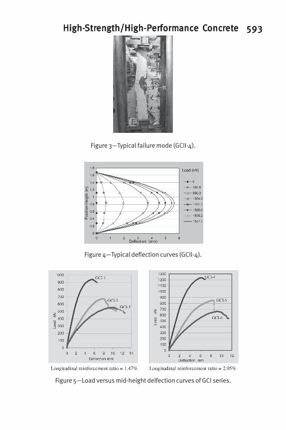
250mm below or above mid-height. The failure was due to crushing of concrete in the compressed face near the mid-height of columns. The failures were generally brittle. A sudden and explosive failure with a short post-peak behavior was characterized by columns with smaller load eccentricity, higher concrete strength and higher reinforcement ratio. Figure 3 shows a typical failure mode of columns.
Load-deflection curves
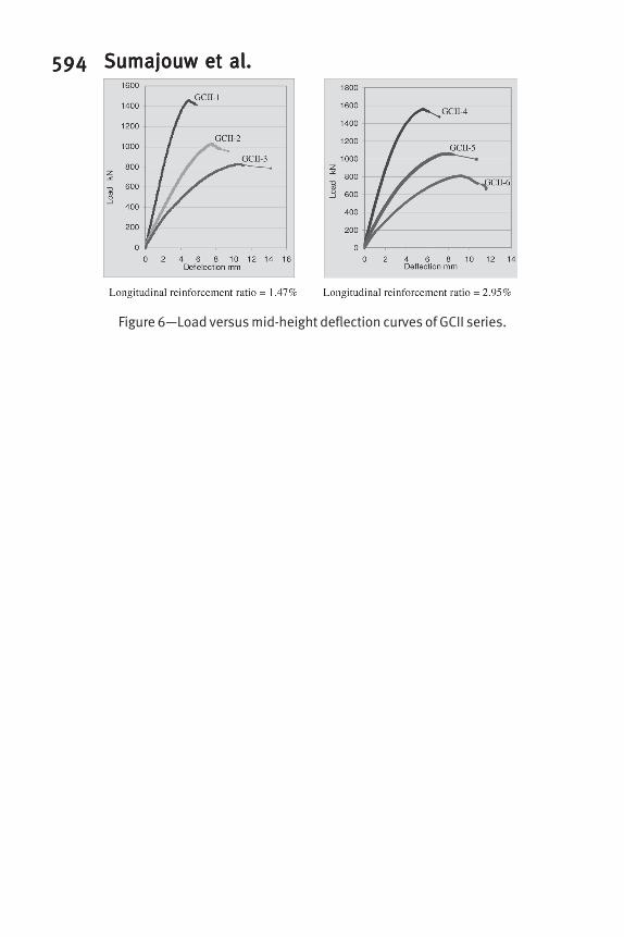
Typical deflections curves along the height of the column at various loads are shown in Figure 4. The load versus mid-height deflection graph of test columns are presented in Figure 5 and Figure 6.
In general, the deflections decreased with an increase in the concrete compressive
strength and an increase in the percentage of longitudinal reinforcement ratio. As expected, lateral deflections increased with the increase in load eccentricity.
Load capacity
The load capacity of columns is influenced by load-eccentricity, concrete compressive strength, and longitudinal reinforcement ratio. As expected, as the load eccentricity decreased, the load capacity of columns increased. The load capacity also increased when the compressive strength of concrete and the longitudinal reinforcement ratio increased (Table 3).
COLUMN STRENGTH CALCULATION
The load capacity of geopolymer concrete columns was calculated using a simplified stability analysis proposed earlier by Rangan (14) as well as by Section 10.12 of the ACI Building Code ACI 318-02 (15).
Simplified stability analysis
The strength of geopolymer concrete columns was calculated using a simplified stability analysis of a standard pin-ended column as reported previously by Rangan (14). This method was proved to be accurate in the case of OPC concrete slender columns under
High-High-High-High-High-StrStrStrStrStrenenenenengggggth/High-Pth/High-Pth/High-Pth/High-Pth/High-Perererererffffformormormormormancancancancance Ce Ce Ce Ce Conconconconconcrrrrreteteteteteeeee 585585585585585
equal load eccentricities (25) and high strength OPC concrete slender columns under unequal load eccentricities (26).
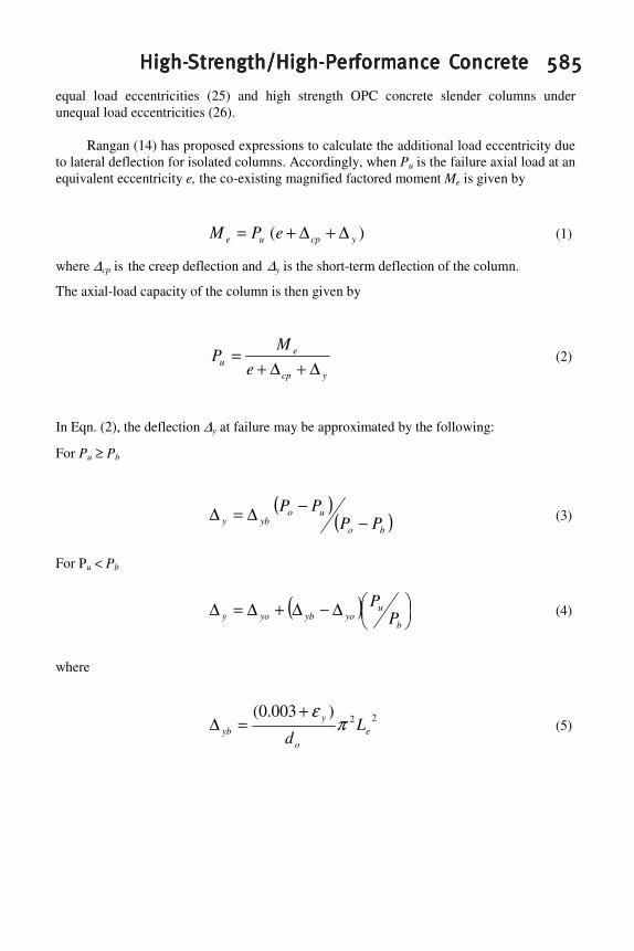
Rangan (14) has proposed expressions to calculate the additional load eccentricity due
to lateral deflection for isolated columns. Accordingly, when Pu is the failure axial load at an equivalent eccentricity e, the co-existing magnified factored moment Me is given by
)( ycpue ePM ∆+∆+= (1)
where ∆cp is the creep deflection and ∆y is the short-term deflection of the column.
The axial-load capacity of the column is then given by
ycp
eu e
MP
∆+∆+= (2)
In Eqn. (2), the deflection ∆y at failure may be approximated by the following:
For Pu ≥ Pb
( )( )bo
uoyby PP
PP−
−∆=∆ (3)
For Pu < Pb
( ) ���
���∆−∆+∆=∆
b
uyoybyoy P
P (4)
where
22)003.0(e
o
yyb L
dπ
ε+=∆ (5)
586586586586586 Sumajouw et al.Sumajouw et al.Sumajouw et al.Sumajouw et al.Sumajouw et al.
and
o
eyyo d
L2
26.1
πε
=∆ (6)
In these expressions, Pb is the strength of column cross-section at balanced failure
conditions, Po is the pure axial load capacity of column cross-section, εy is the yield strain of reinforcing steel, do is the depth of extreme layer of tensile steel measured from the compression face, and Le is the effective length of column.
Based on the expressions given above, the following steps are performed to calculate the strength of slender columns. In these calculations ∆cp was taken as zero for the test columns.
1. For a given column cross-section, construct the strength interaction diagram N versus M. The usual flexural analysis of reinforced concrete section was used to calculate the strength interaction as described by Warner et al (24).
2. Estimate a suitable value for the failure load, Pu. 3. Take Pu = N and hence determine the corresponding value of M from the strength
interaction diagram of the column cross-section. Take M = Me. 4. Calculate ∆y from Eqn. 3 or Eqn. 4 whichever is appropriate. 5. For these values of Me and ∆y, calculate Pu from Eqn. 2. 6. Use this new value of Pu and repeat steps 3 to 5 until the results convergence. A summary of comparison of calculated and test failure loads of geopolymer concrete
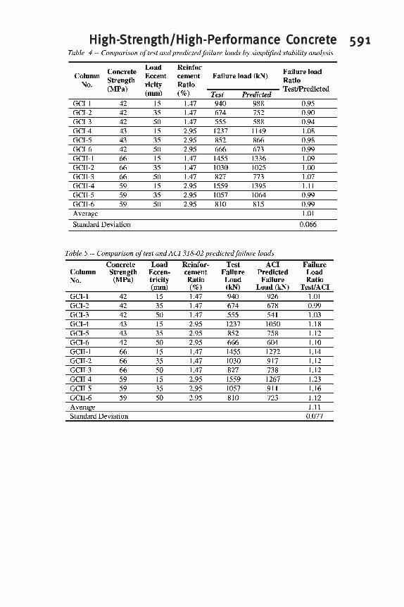
columns tested in this study is given in Table 4. It can be seen that correlation between the results is excellent.
ACI 318-02 Building Code
The load capacity of geopolymer concrete column was calculated using the design provisions contained in Section 10.12 of ACI 318-02 (15). In these calculations, the strength reduction factor was taken as unity.
A summary of comparison of the experimental values with calculated values is given in
Table 5. A good correlation between the values is seen.
High-High-High-High-High-StrStrStrStrStrenenenenengggggth/High-Pth/High-Pth/High-Pth/High-Pth/High-Perererererffffformormormormormancancancancance Ce Ce Ce Ce Conconconconconcrrrrreteteteteteeeee 587587587587587
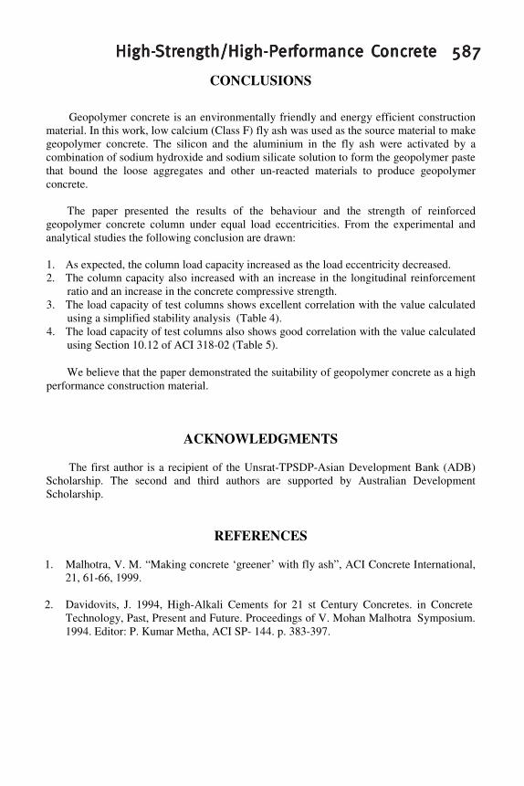
CONCLUSIONS
Geopolymer concrete is an environmentally friendly and energy efficient construction material. In this work, low calcium (Class F) fly ash was used as the source material to make geopolymer concrete. The silicon and the aluminium in the fly ash were activated by a combination of sodium hydroxide and sodium silicate solution to form the geopolymer paste that bound the loose aggregates and other un-reacted materials to produce geopolymer concrete.
The paper presented the results of the behaviour and the strength of reinforced
geopolymer concrete column under equal load eccentricities. From the experimental and analytical studies the following conclusion are drawn:
1. As expected, the column load capacity increased as the load eccentricity decreased. 2. The column capacity also increased with an increase in the longitudinal reinforcement
ratio and an increase in the concrete compressive strength. 3. The load capacity of test columns shows excellent correlation with the value calculated
using a simplified stability analysis (Table 4). 4. The load capacity of test columns also shows good correlation with the value calculated
using Section 10.12 of ACI 318-02 (Table 5).
We believe that the paper demonstrated the suitability of geopolymer concrete as a high performance construction material.
ACKNOWLEDGMENTS
The first author is a recipient of the Unsrat-TPSDP-Asian Development Bank (ADB) Scholarship. The second and third authors are supported by Australian Development Scholarship.
REFERENCES
1. Malhotra, V. M. “Making concrete ‘greener’ with fly ash”, ACI Concrete International, 21, 61-66, 1999.
2. Davidovits, J. 1994, High-Alkali Cements for 21 st Century Concretes. in Concrete Technology, Past, Present and Future. Proceedings of V. Mohan Malhotra Symposium. 1994. Editor: P. Kumar Metha, ACI SP- 144. p. 383-397.
588588588588588 Sumajouw et al.Sumajouw et al.Sumajouw et al.Sumajouw et al.Sumajouw et al.
3. Metha, P. K. “Reducing the environmental impact of concrete”, ACI Concrete
International, 23, 61-66, 2001. 4. Malhotra, V. M. “Introduction: Sustainable development and concrete technology, ACI
Board Task Group on Sustainable Development”, ACI Concrete International, 24, 22, 2002.
5. McCaffrey, R. “Climate change and the cement industry”, Global cement and lime magazine (Environmental special issue), 15-19, 2002.
6. Davidovits, J. “Chemistry of geopolymer systems, terminology”, in Proceedings of Geopolymer International Conferences 1999.
7. ACI 232.2R-03, “Use of Fly Ash in Concrete”, Reported by ACI Committee 232, American Concrete Institute, Farmington Hills, MI, 2003.
8. Bhanumathidas, N. and Kalidas, N., “Fly ash for sustainable development”, Ark communications, Chennai, 2004.
9. Hardjito, D., Wallah, S. E., Sumajouw, D. M. J. & Rangan B. V. “On the development of fly ash based geopolymer concrete”, Technical paper No. 101-M52, ACI Material Journal, Vol. 101, No. 6, November-December 2004, American Concrete Institute.
10. Hardjito, D., Wallah, S. E., Sumajouw, D. M. J. & Rangan B. V. “Properties of Geopolymer Concrete with Fly Ash as Source Material: Effect of Mixture Composition”. In Proceedings of the Seventh CANMET/ACI International Conference on Recent Advances in Concrete Technology, Las Vegas, SP-222-8, pp. 109-118, 2004.
11. Hardjito, D., Wallah, S. E., Sumajouw, D. M. J. & Rangan B. V. “Brief Review on Development of Geopolymer Concrete”. George C. Hoff Symposium on High-Performance Concrete and Concrete for Marine Environment, Las Vegas, pp. 63-72, 2004.
12. Wallah, S. E., Hardjito D., Sumajouw, D. M. J., and Rangan, B. V. “Sulfate resistance of fly ash-based geopolymer concrete”, In Proceedings of Concrete in the Third Millennium: The 21st Biennial Conference of The Concrete Institute of Australia 2003, 205-212, 2003.
13. Wallah, S. E., Hardjito, D., Sumajouw D. M. J., and Rangan, B. V. “Creep Behaviour of Fly Ash-Based Geopolymer Concrete”. In proceedings of the Seventh CANMET/ACI International Conference on Recent Advances in Concrete Technology, Las Vegas, pp. 49 – 59, 2004.
High-High-High-High-High-StrStrStrStrStrenenenenengggggth/High-Pth/High-Pth/High-Pth/High-Pth/High-Perererererffffformormormormormancancancancance Ce Ce Ce Ce Conconconconconcrrrrreteteteteteeeee 589589589589589
14. Rangan, B.V., “Strength of Reinforced Concrete Slender Columns”, ACI Structural
Journal, Vol. 87. No.1, Jan-Feb. 1990 pp.32-38. 15. ACI 318-02., “Building Code Requirements for Structural Concrete”, Reported by ACI
Committee 318, American Concrete Institute, Farmington Hills, MI, 2002.
16. Davidovits, J. “Ancient and modern concretes: What is the real differences?”, ACI Concrete International, 9:23-28 , 1987.
17. Davidovits, J. & Sawyer, J. L. Early high-strength mineral, US Patent No.4, 509,985, 1985.
18. Balaguru, P N, Kurtz, S, & Rudolph, J. “Geopolymer for repair and rehabilitation of reinforced concrete beams”, The State University of New Jersey Rutgers, 1997.
19. Van Jaarsveld, J. G. S., Van Deventer, J. S. J., & Schartzman, A. “The potential use of geopolymer materials to immobilise toxic metals: Part II, Material and leaching characteristics”, Mineral Engineering, 12(1)75-91, 1999.
20. Palomo, A., Grutzeck, M. W., & Blanco, M. T. “Alkali-activated fly ash cement for future”, Cement and Concrete Research, 29:1323-1329, 1999.
21. Swanepoel, J. C. & Strydom, C. A. “Utilisation of fly ash in geopolymeric material”, Journal of Applied Geochemistry, 17:1143-1148, 2002.
22. Van Jaarsveld, J. G. S., Van Deventer J. S. J., & Lukey, G. C. “The effect of composition and temperature on the properties of fly ash and kaolinite-based geopolymers”, Chemical Engineering Journal, 4001:1-11, 2002.
23. Kilpatrick. A. E. The behaviour of high-strength composite concrete columns. PhD Thesis, Curtin University of Technology, Perth, Australia, 1996.
24. Warner, R.F., Rangan, B.V., Hall, A.S., & Faulkes, K. A. “Concrete Structures”. Melbourne, Longman, 1998.
25. Lloyd, N.A., and Rangan, B.V., “Studies on high-strength concrete columns under eccentric compression”, ACI Structural Journal, V.93, No.6, Nov-Dec., 1996, pp. 631-638.
26. Sarker P.K., and Rangan, B.V., “Reinforced concrete columns under unequal load eccentricities”, ACI Structural Journal, V.100, No.4, July-August 2003, pp.519-528.
590590590590590 Sumajouw et al.Sumajouw et al.Sumajouw et al.Sumajouw et al.Sumajouw et al.
High-High-High-High-High-StrStrStrStrStrenenenenengggggth/High-Pth/High-Pth/High-Pth/High-Pth/High-Perererererffffformormormormormancancancancance Ce Ce Ce Ce Conconconconconcrrrrreteteteteteeeee 591591591591591
592592592592592 Sumajouw et al.Sumajouw et al.Sumajouw et al.Sumajouw et al.Sumajouw et al.
Figure 1—(a) Geometry and details of geopolymer concrete columns;(b) end assembalage arrangement for column tests.
Figure 2—Front view of geopolymer concrete column before the test.
High-High-High-High-High-StrStrStrStrStrenenenenengggggth/High-Pth/High-Pth/High-Pth/High-Pth/High-Perererererffffformormormormormancancancancance Ce Ce Ce Ce Conconconconconcrrrrreteteteteteeeee 593593593593593
Figure 3—Typical failure mode (GCII-4).
Figure 4—Typical deflection curves (GCII-4).
Figure 5—Load versus mid-height delfection curves of GCI series.
594594594594594 Sumajouw et al.Sumajouw et al.Sumajouw et al.Sumajouw et al.Sumajouw et al.
Figure 6—Load versus mid-height deflection curves of GCII series.


![HempCreate: the art of hemp based Geopolymer extrusion. · The material aspect Extrude [print] buildings Necessary to; understand Geopolymer chemistry discover a suitable Geopolymer](https://img.pdfslide.us/doc/110x75/5f6499b949fcf85d37753e59/hempcreate-the-art-of-hemp-based-geopolymer-the-material-aspect-extrude-print.jpg)