Embed Size (px)
Citation preview

BEFORE THE ENVIRONMENTAL APPEALS BOARD UNITED STATES ENVIRONMENTAL PROTECTION AGENCY
WASHINGTON, D.C.
In re: Shell Gulf of Mexico, Inc. Permit No. R10OCS/PSD-AK-09-01 and Shell Offshore, Inc. Permit No. R10OCS/PSD-AK-2010-01
) ) ) ) ) ) )) ) ) ) )
EXHIBITS IN SUPPORT OF PETITION FOR REVIEW
NATURAL RESOURCES DEFENSE COUNCIL, NATIVE VILLAGE OF POINT HOPE, RESISTING ENVIRONMENTAL DESTRUCTION ON INDIGENOUS LANDS
(REDOIL), ALASKA WILDERNESS LEAGUE, AUDUBON ALASKA, CENTER FOR BIOLOGICAL DIVERSITY, NORTHERN ALASKA ENVIRONMENTAL CENTER,
OCEAN CONSERVANCY, OCEANA, PACIFIC ENVIRONMENT, and SIERRA CLUB

Statement of Basis – Permit No. R10OCS/PSD-AK-09-01 Frontier Discoverer Drillship – Chukchi Sea Exploration Drilling Program
74
In order to detect a major failure of the CDPF control devices, EPA is also proposing a visible emissions (opacity) limit in addition to the PM emission limit described above. EPA proposes that visible emissions from the engines, excluding condensed water vapor, shall not reduce visibility through the exhaust effluent more than 20 percent averaged over any six consecutive minutes.
4.4.4 PM BACT for the Diesel-Fired Boilers (FD-21 to FD-22)
Step 2 – Eliminate technically infeasible control options No PM controls were found in the RBLC or CA-BACT search for small boilers. 15 Although it may be theoretically possible to design an ESP or a fabric filter for the small boilers on the Discoverer, one factor limiting the application of a fabric filter or an ESP on these boilers is that more than 50 percent of the PM from diesel fired boilers is condensable PM which would not be collected in a fabric filter or ESP at normal exhaust gas temperatures. As shown in Appendix A, the PM emissions for each boiler are 0.38 ton per year. Based on these factors, EPA considers a fabric filter or an ESP to be technically infeasible for control of PM from the boilers on the Discoverer. The use of ultra-low sulfur fuel for combustion will minimize the sulfate fraction of the PM emissions. Step 3 – Rank the remaining technologies by control effectiveness The only technically feasible PM control option for the two boilers (FD-21 and FD-22) is good combustion practices. Step 4 – Evaluate the most effective control based on a case-by-case consideration of energy, environmental, and economic impacts Since the top control option from Step 3 (good combustion practices) is proposed as BACT, this step is not required. Step 5 – Select PM BACT for the Diesel-Fired Boilers EPA is proposing that good combustion practices represent BACT for PM for the diesel-fired boilers on the Discoverer. Good combustion practice for PM control essentially consists of operating and maintaining the boilers according to the manufacturer’s recommendations to maximize fuel efficiency and minimize emissions. More specifically, EPA proposes the following good combustion practices, in addition to the emission limit set forth below, as BACT for the diesel-fired boilers on the Discoverer:.
• Operating personnel must be trained to identify signs of improper operation and maintenance, including visible plumes, and instructed to report these to the maintenance specialist,
15 These control technologies are not found in practice because of the high cost of such control technology and the very small potential reduction in PM emissions.
Exhibit 5, page 40 of 80

Statement of Basis – Permit No. R10OCS/PSD-AK-09-01 Frontier Discoverer Drillship – Chukchi Sea Exploration Drilling Program
75
• At least one full-time equipment maintenance specialist must be on board at all times during drilling activities, • Each emission unit must be inspected by the maintenance specialist at least once a week for proper operation and maintenance consistent with the manufacturer’s recommendations, • The operation and maintenance manual provided by the manufacturer for each emission unit must be maintained on board the Discoverer at all times, • The manufacturer’s recommended operation and scheduled maintenance procedures must be followed for each emission unit.
EPA proposes that the permit include a condition requiring the permittee to follow the good combustion practices listed above. EPA proposes that an emission limit representative of PM BACT for the boilers is 0.0235 pounds per million Btu (lb/MMBtu). This emission limit was derived from the emission rate and boiler size information provided in Appendix A. In order to detect a major operating problem with the boilers, EPA is also proposing a visible emissions (opacity) limit in addition to the PM limit described above. EPA proposes that visible emissions from the boilers, excluding condensed water vapor, shall not reduce visibility through the exhaust effluent more than 20 percent averaged over any six consecutive minutes.
4.4.5 PM BACT for the Incinerator (FD-23)
Step 2 – Eliminate technically infeasible control options Based on review of the RBLC and CA-BACT, the available control technologies for the Discoverer’s incinerator (FD-23) are an ESP and good combustion practices. The incinerator listed in the RBLC with an ESP was rated at 350 tons per day (29,167 lb/hr), which is over 100 times the size of the incinerator on the Discoverer. Communication with TeamTec, the manufacturer of the incinerator on the Discoverer, indicated that they were not aware of any control technologies that have been installed on this model of incinerator for control of any of the pollutants including PM (Shell 2/23/09 Rev. App., Appendix F, Footnote 39, pages 105 to 112). By letter to EPA dated December 13, 2009, Shell provided a study conducted by GI Development LLC to evaluate PM control options for the incinerator (Shell 12/13/09 Supp. App.). The GI Development LLC study evaluated a dry ESP, a wet ESP, a venturi scrubber and a ceramic fiber baghouse. Step 3 – Rank the remaining technologies by control effectiveness
1. Ceramic fabric baghouse – 99 percent control 2. Venturi scrubber – 90 percent control
Exhibit 5, page 41 of 80

Statement of Basis – Permit No. R10OCS/PSD-AK-09-01 Frontier Discoverer Drillship – Chukchi Sea Exploration Drilling Program
76
3. Dry ESP – 75 percent control at the quoted size 4. Wet ESP – 75 percent control at the quoted size 5. Good combustion practices.
Step 4 – Evaluate the most effective control based on a case-by-case consideration of energy, environmental, and economic impacts The cost effectiveness value for the ceramic fiber baghouse based on a capital equipment cost of $230,000 was calculated to be $65,986/ton of PM removed. The high cost effectiveness value was due to both the high capital cost and the relatively low amount of potential PM removed (about 0.5 ton/year). This cost effectiveness value is higher than EPA considers reasonable for a BACT determination. Therefore, the ceramic fabric baghouse control device was eliminated from consideration in the BACT process. The cost effectiveness value for the venturi scrubber based on a capital equipment cost of $150,000 was calculated to be $49,490/ton of PM removed. The high cost effectiveness value was due to both the high capital cost and the relatively low amount of potential PM removed (about 0.5 ton/year). This cost effectiveness value is higher than EPA considers reasonable for a BACT determination. Therefore, the venturi scrubber control device was eliminated from consideration in the BACT process. Since both the dry and the wet ESP control devices have a higher capital cost ($420,000 and $175,000 respectively) and a lower PM control percentage than the venturi scrubber, the cost effectiveness values for either ESP is greater than for the venturi scrubber. Therefore, the dry and wet ESP control devices were eliminated from consideration in the BACT process. The remaining control option is good combustion practices. Step 5 – Select PM BACT for the Incinerator Good combustion practices are determined to represent BACT for PM for the incinerator. Good combustion practice for PM control essentially consists of operating and maintaining the incinerator according to the manufacturer’s recommendations to maximize fuel efficiency and minimize emissions. More specifically, good combustion practices for the incinerator consist of the following:
• Operating personnel must be trained to identify signs of improper operation and maintenance, including visible plumes, and instructed to report these to the maintenance specialist, • At least one full-time equipment maintenance specialist must be on board at all times during drilling activities, • Each emission unit must be inspected by the maintenance specialist at least once a week for proper operation and maintenance consistent with the manufacturer’s recommendations,
Exhibit 5, page 42 of 80
Statement of Basis – Permit No. R10OCS/PSD-AK-09-01 Frontier Discoverer Drillship – Chukchi Sea Exploration Drilling Program
77
• The operation and maintenance manual provided by the manufacturer for each emission unit must be maintained on board the Discoverer at all times, • The manufacturer’s recommended scheduled operation and maintenance procedures must be followed for each emission unit.
EPA proposes that the permit include a condition requiring the permittee to follow the good combustion practices listed above. In order to minimize emissions of PM, EPA proposes that the permit require that Shell develop and implement a written waste segregation work practice plan to ensure that non-combustible items containing heavy metals that could be volatilized and emitted from the incinerator as PM are not introduced into the incinerator. The PM emission limit representative of BACT for the incinerator is 8.20 pounds of PM10 per ton of waste burned and 7.00 pounds of PM2.5 per ton of waste burned. These emission limits are identical to the emission factors presented in the emission inventory in Appendix A.
4.5 CO and VOC BACT Analysis
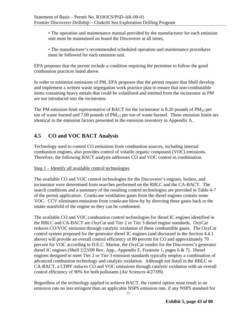
Technology used to control CO emissions from combustion sources, including internal combustion engines, also provides control of volatile organic compound (VOC) emissions. Therefore, the following BACT analysis addresses CO and VOC control in combination. Step 1 – Identify all available control technologies The available CO and VOC control technologies for the Discoverer’s engines, boilers, and incinerator were determined from searches performed on the RBLC and the CA-BACT. The search conditions and a summary of the resulting control technologies are provided in Table 4-7 of the permit application. Crankcase ventilation gases from the diesel engines contain some VOC. CCV eliminates emissions from crankcase blow-by by directing these gases back to the intake manifold of the engine so they can be combusted. The available CO and VOC combustion control technologies for diesel IC engines identified in the RBLC and CA-BACT are OxyCat and Tier 2 or Tier 3 diesel engine standards. OxyCat reduces CO/VOC emission through catalytic oxidation of these combustible gases. The OxyCat control system proposed for the generator diesel IC engines (and discussed in the Section 4.4.1 above) will provide an overall control efficiency of 80 percent for CO and approximately 70 percent for VOC according to D.E.C. Marine, the OxyCat vendor for the Discoverer’s generator diesel IC engines (Shell 2/23/09 Rev. App., Appendix F, Footnote 1, pages 6 & 7). Diesel engines designed to meet Tier 2 or Tier 3 emission standards typically employ a combination of advanced combustion technology and catalytic oxidation. Although not listed in the RBLC or CA-BACT, a CDPF reduces CO and VOC emissions through catalytic oxidation with an overall control efficiency of 90% for both pollutants (Air Sciences 4/27/09). Regardless of the technology applied to achieve BACT, the control option must result in an emission rate no less stringent than an applicable NSPS emission rate, if any NSPS standard for
Exhibit 5, page 43 of 80

Statement of Basis – Permit No. R10OCS/PSD-AK-09-01 Frontier Discoverer Drillship – Chukchi Sea Exploration Drilling Program
78
that pollutant is applicable to the source. 40 C.F.R. § 52.21(b)(12)(definition of BACT). EPA has promulgated exhaust emission standards for stationary IC engines under the NSPS Subpart IIII which specifies that engine manufacturers must certify their 2007 and later engines to the applicable emission standard for new nonroad engines in 40 C.F.R. § 89.112 (and several other sections). 40C.F.R. § 60.4201(a). Engines designed to meet Tier 2 or Tier 3 PM emission standards typically employ a combination of low PM emitting engine designs and DPF or CDPF. For diesel IC engines manufactured to meet the Tier 3 emission standards such as the three 540 hp MLC compressor engines (FD-9 to FD-11) and the 250 hp Logging Unit Winch engine (FD-19), the applicable CO emission standard is 3.5 grams per kilowatt hour (g/kW-hr). 40 C.F.R. § 89.112(a) Table 1. The VOC emission limit for Tier 3 engines is expressed as a combined value with NOx (4.0 g/kW-hr). No CO or VOC control technologies were found in the RBLC and CA-BACT searches for diesel-fired boilers less than or equal to 100 MMBtu/hr or for incinerators, nor are any CO or VOC control technologies found in practice for existing small boilers or incinerators. Therefore, good combustion practice is the only available control technology for consideration in this analysis for the diesel-fired boilers and the incinerator.
4.5.1 CO and VOC BACT for the Generator Diesel IC Engines (FD-1 to FD-6)
Step 2 – Eliminate technically infeasible control options The available control technologies for the generator diesel IC engines are OxyCat, CDPF, Tier 2 or Tier 3 level controls, and CCV. Tier 2 or Tier 3 level controls are intrinsic to the original engine design; and, therefore, are not considered technically feasibility since they are not part of the design of the Discoverer’s existing Caterpillar D399 diesel engines. As discussed above in Section 4.4.1, the primary difference between an OxyCat system and a CDPF is that the OxyCat system is constructed with an open flow catalyst matrix. In contrast, the CDPF is constructed with a catalyst matrix where the inlet channels of the catalyst matrix are plugged at the downstream end, forcing the exhaust gases to flow through the pores of the catalyst matrix and out the adjacent channels, which are plugged at the inlet end of the matrix. Because of this design difference, a CDPF achieves a higher percentage reduction of PM emissions but approximately the same percentage reduction for VOC and CO as compared to an OxyCat system, although at the expense of a higher pressure drop across the catalyst matrix. As also discussed above, the higher pressure drop of the CDPF is of concern because, as described in Section 4.3.1, the generator diesel IC engines will be equipped with the SCR system for NOx control. The SCR catalyst imposes a backpressure on the engines due to the pressure drop required to move the exhaust gases through the SCR catalyst matrix. Adding the additional pressure drop associated with a CDPF could result in an excessive backpressure on the engines. D.E.C. Marine addressed the possibility of designing a CDPF to be used with the SCR system (Shell 2/23/09 Rev. App., Appendix F, Footnote 41, page 113). Since a CDPF has not been included with their SCR systems in the past, a feasibility study would have to be conducted before final design. Several considerations would have to be addressed including the additional cross-sectional area needed for the CDPF catalyst matrix (perhaps as much as 50% larger than for an OxyCat matrix), the temperature profiles to determine how well the captured soot would
Exhibit 5, page 44 of 80

Statement of Basis – Permit No. R10OCS/PSD-AK-09-01 Frontier Discoverer Drillship – Chukchi Sea Exploration Drilling Program
79
be oxidized in the CDPF, the increased backpressure imposed and the manual cleaning frequency (or filter element exchange) required to keep the backpressure within specifications. D.E.C. Marine states that they are not aware of any applications of CDPF systems on older heavy duty marine engines without modern electronic controlled fuel injection. Since CDPF systems are not commercially available in combination with SCR systems for diesel engines such as the Discoverer’s generator diesel IC engines, EPA believes that CDPF systems are technically infeasible for this specific application.16 Step 3 – Rank the remaining technologies by control effectiveness The remaining technically feasible controls for the generator diesel IC engines include OxyCat and good combustion practices for control of exhaust gas emissions. Step 4 – Evaluate the most effective control based on a case-by-case consideration of energy, environmental, and economic impacts The most efficient available technology is an OxyCat system with estimated control efficiency of 80% for CO and 70% for VOC. The design proposed by D.E.C. Marine incorporates oxidation catalyst downstream of the SCR catalyst in the same converter shell, which results in a more compact and economical system than having separate devices. The OxyCat system is expected to reduce CO emissions to <0.179 g/kW-hr and VOC emissions to <0.0229 g/kW-hr. In addition to the exhaust gases from the engine, the diesel generator engines produce emissions from the crankcase, which must be vented to prevent pressure buildup from combustion gases that escape around the piston rings during the combustion stroke. As discussed above in Section 4.4.1, EPA is proposing that CCV represents BACT for PM. Installation of CCV will also control CO and VOC emissions by recycling them back to the intake manifold so that they can be combusted. Step 5 – Select CO and VOC BACT for the Generator Diesel IC Engines EPA proposes that BACT for CO and VOC for the generator diesel IC engines is an emission limit of 0.1790 g/kW-hr for CO and 0.0230 g/kW-hr for VOC based on the use of OxyCat technology.
16 Even if a CDPF was technologically feasible in this specific application, Shell estimated the cost effectiveness of a CDPF for the generator engines and found the cost effectiveness values to be in the $20,000 to $30,000 per ton of PM removed (see Appendix C of Shell 2/23/09 Rev. App. for the detailed cost calculations). Using a similar cost effectiveness calculation procedure, EPA estimated that the cost effectiveness value for a CDPF to control CO and VOC was approximately $40,000 per ton of CO and VOC removed. These cost effectiveness values exceed what EPA believes is representative of BACT for these engines.
Exhibit 5, page 45 of 80

Statement of Basis – Permit No. R10OCS/PSD-AK-09-01 Frontier Discoverer Drillship – Chukchi Sea Exploration Drilling Program
80
4.5.2 CO and VOC BACT for the Compressor Diesel IC Engines (FD- 9 to FD-11) and the Logging Unit Winch Engine (FD-19) (all Tier 3 Engines)
Step 2 – Eliminate technically infeasible control options
Shell proposed that engines meeting the Tier 3 emission standards represent BACT. However, there is no technical reason why add-on controls can not be considered for Tier 3 engines. The available control technologies for the Tier 3 diesel IC engines include CDPF, OxyCat, and good combustion practices. CCV is included as an inherent feature of the Tier 3 engines.
Step 3 – Rank the remaining technologies by control effectiveness
The technically feasible control technologies for the smaller diesel engines are ranked by control effectiveness:
1. CDPF – 80% control for CO and VOC 2. OxyCat – 47% control for CO and VOC 3. Good combustion practices
Step 4 – Evaluate the most effective control based on a case-by-case consideration of energy, environmental, and economic impacts On December 22, 2009, Shell submitted CO cost effectiveness calculations for CDPF and Oxy Cat controls for the compressor engines and the Logging Unit Winch engine (Environ 212/22/09). The cost effectiveness value for a CDPF for each of the compressor engines was calculated to be $9,848/ton of CO removed. The cost effectiveness value for an OxyCat for each of the compressor engines was calculated to be $4,323/ton of CO removed. The cost effectiveness values were calculated assuming the baseline emission rate was equal to the Tier 3 CO engine standard of 3.5 g/kW-hr. Since the cost effectiveness value for the CDPF was near the high end of the range that EPA considers reasonable, the incremental cost effectiveness value between an OxyCat and a CDPF was evaluated to determine whether the additional cost to move from an OxyCat to a CDPF for the compressor engines was justified. The incremental cost effectiveness value was calculated to be $17,700/ton of CO removed. Because the incremental cost effectiveness value between an OxyCat and a CDPF is so large, EPA proposes that an OxyCat is representative of BACT for the compressor engines. In the December 22, 2009 analysis, the cost effectiveness values for a CDPF and an OxyCat for the Logging Unit Winch engine were calculated (Environ 12/22/09). The cost effectiveness value for a CDPF for the Logging Unit Winch engine was calculated to be $3,329/ton of CO removed, a cost effectiveness value that EPA considers reasonable. Therefore, EPA proposes that a CDPF is representative of BACT for the Logging Unit Winch engine. Step 5 – Select CO/VOC BACT for the Compressor and Logging Unit Winch Diesel IC Engines EPA proposes that BACT for CO from the compressor diesel IC engines is an emission limit of 1.86 g/kW-hr based on the use of an OxyCat. EPA proposes that BACT for CO from the Logging Unit Winch diesel IC engine is an emission limit of 0.70 g/kW-hr based on the use of a
Exhibit 5, page 46 of 80
Statement of Basis – Permit No. R10OCS/PSD-AK-09-01 Frontier Discoverer Drillship – Chukchi Sea Exploration Drilling Program
81
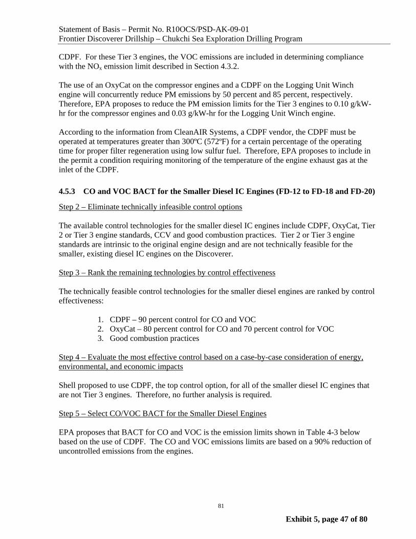
CDPF. For these Tier 3 engines, the VOC emissions are included in determining compliance with the NOx emission limit described in Section 4.3.2. The use of an OxyCat on the compressor engines and a CDPF on the Logging Unit Winch engine will concurrently reduce PM emissions by 50 percent and 85 percent, respectively. Therefore, EPA proposes to reduce the PM emission limits for the Tier 3 engines to 0.10 g/kW-hr for the compressor engines and 0.03 g/kW-hr for the Logging Unit Winch engine. According to the information from CleanAIR Systems, a CDPF vendor, the CDPF must be operated at temperatures greater than 300ºC (572ºF) for a certain percentage of the operating time for proper filter regeneration using low sulfur fuel. Therefore, EPA proposes to include in the permit a condition requiring monitoring of the temperature of the engine exhaust gas at the inlet of the CDPF.
4.5.3 CO and VOC BACT for the Smaller Diesel IC Engines (FD-12 to FD-18 and FD-20)
Step 2 – Eliminate technically infeasible control options The available control technologies for the smaller diesel IC engines include CDPF, OxyCat, Tier 2 or Tier 3 engine standards, CCV and good combustion practices. Tier 2 or Tier 3 engine standards are intrinsic to the original engine design and are not technically feasible for the smaller, existing diesel IC engines on the Discoverer. Step 3 – Rank the remaining technologies by control effectiveness The technically feasible control technologies for the smaller diesel engines are ranked by control effectiveness:
1. CDPF – 90 percent control for CO and VOC 2. OxyCat – 80 percent control for CO and 70 percent control for VOC 3. Good combustion practices
Step 4 – Evaluate the most effective control based on a case-by-case consideration of energy, environmental, and economic impacts Shell proposed to use CDPF, the top control option, for all of the smaller diesel IC engines that are not Tier 3 engines. Therefore, no further analysis is required. Step 5 – Select CO/VOC BACT for the Smaller Diesel Engines EPA proposes that BACT for CO and VOC is the emission limits shown in Table 4-3 below based on the use of CDPF. The CO and VOC emissions limits are based on a 90% reduction of uncontrolled emissions from the engines.
Exhibit 5, page 47 of 80

Statement of Basis – Permit No. R10OCS/PSD-AK-09-01 Frontier Discoverer Drillship – Chukchi Sea Exploration Drilling Program
82
Table 4-3 - CO and VOC Emission Limits for the Smaller Diesel IC Engines
Emission Unit Number and Engine Name
VOC Emission Limit
(g/kW-hr)
CO Emission Limit
(g/kW-hr)
FD-12 & 13, HPU Engines 0.20 0.40
FD-14 & 15, Deck Crane Engines 0.0640 0.220
FD-16 & 17, Cementing Unit Engines
0.20 0.40
FD-18 Cementing Unit Engine 0.270 0.880
FD-20, Logging Unit Generator Engine
0.750 0.550
According to the information from CleanAIR Systems, a CDPF vendor, the CDPF must be operated at temperatures greater than 300ºC (572ºF) for a certain percentage of the operating time for proper filter regeneration using low sulfur fuel. Therefore, EPA proposes to include in the permit a condition requiring monitoring of the temperature of the engine exhaust gas at the inlet of the CDPF. In addition to the exhaust gases from the engine, the smaller diesel IC engines produce emissions from the crankcase, which must be ventilated to prevent pressure buildup from combustion gases that escape around the piston rings during the combustion stroke. EPA believes that CCV represents BACT for PM. Installation of CCV will also control CO and VOC emissions by recycling them back to the intake manifold so that they can be combusted.
4.5.4 CO and VOC BACT for the Diesel-Fired Boilers (FD-21 to FD-22) and the Incinerator (FD 23)
Step 2 – Eliminate technically infeasible control options No CO or VOC controls were found in the RBLC or CA-BACT searches for small boilers and incinerators. As shown in Appendix A, the CO and VOC emissions for each boiler are 1.25 tons per year and 0.02 tons per year, respectively. Similarly, the CO and VOC emissions for the incinerator are 1.69 tons per year and 0.16 tons per year, respectively. Step 3 – Rank the remaining technologies by control effectiveness The only technically feasible CO and VOC control option for the two boilers (FD-21 and FD-22) and the incinerator (FD-23) is good combustion practices. Step 4 – Evaluate the most effective control based on a case-by-case consideration of energy, environmental, and economic impacts Since the only control option from Step 3 (good combustion practices) is proposed as BACT, this step is not required.
Exhibit 5, page 48 of 80
Statement of Basis – Permit No. R10OCS/PSD-AK-09-01 Frontier Discoverer Drillship – Chukchi Sea Exploration Drilling Program
83
Step 5 – Select CO and VOC BACT for the Diesel-Fired Boilers and the Incinerator EPA proposes that good combustion practices represent BACT for CO and VOC for the diesel-fired boilers and the incinerator. Good combustion practice for CO and VOC control essentially consists of operating and maintaining the boilers and the incinerator according to the manufacturer’s recommendations to maximize fuel efficiency and minimize emissions. More specifically, good combustion practices for the boilers and the incinerator consist of the following:
• Operating personnel must be trained to identify signs of improper operation and maintenance, including visible plumes, and instructed to report these to the maintenance specialist, • At least one full-time equipment maintenance specialist must be on board at all times during drilling activities, • Each emission unit must be inspected by the maintenance specialist at least once a week for proper operation and maintenance consistent with the manufacturer’s recommendations, • The operation and maintenance manual provided by the manufacturer for each emission unit must be maintained on board the Discoverer at all times, • The manufacturer’s recommended operation and scheduled maintenance procedures must be followed for each emission unit.
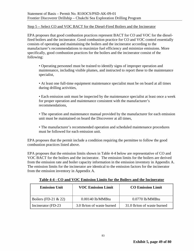
EPA proposes that the permit include a condition requiring the permittee to follow the good combustion practices listed above. EPA proposes that the emission limits shown in Table 4-4 below are representative of CO and VOC BACT for the boilers and the incinerator. The emission limits for the boilers are derived from the emission rate and boiler capacity information in the emission inventory in Appendix A. The emission limits for the incinerator are identical to the emission factors for the incinerator from the emission inventory in Appendix A.
Table 4-4 - CO and VOC Emission Limits for the Boilers and the Incinerator
Emission Unit
VOC Emission Limit CO Emission Limit
Boilers (FD-21 & 22) 0.00140 lb/MMBtu 0.0770 lb/MMBtu
Incinerator (FD-23 3.0 lb/ton of waste burned 31.0 lb/ton of waste burned
Exhibit 5, page 49 of 80

Statement of Basis – Permit No. R10OCS/PSD-AK-09-01 Frontier Discoverer Drillship – Chukchi Sea Exploration Drilling Program
84
4.6 BACT for the Drilling Mud De-gassing Operation (FD-32)
In the letter to EPA dated December 13, 2009, Shell provided additional explanation for the VOC estimate from de-gassing of drilling mud that was originally provided in its May 4, 2009 submission to EPA (Shell 12/13/09 Supp. App.). The VOC emission estimate based on the possibility of drilling a maximum of four wells per year was 128 pounds of VOC per year.
Drilling mud is used to lubricate and carry away heat from the drill bit and to transport drill cuttings to the surface. When the drill passes through a hydrocarbon zone, hydrocarbons in the drill cuttings are carried to the surface (the deck of the Discoverer) with the mud. The mud is directed to the “ditch”, then the shakers and then to the mud pit. These pieces of equipment are exposed to the atmosphere and any trapped gases such as hydrocarbons, water vapor or carbon dioxide flash out of the mud. If high concentrations of hydrocarbons from the mud are detected, the mud it diverted to a mud separator where gases flashed from the mud are directed through a 10 inch diameter pipe and vented at the top of the drilling derrick as a safety precaution to prevent exposure to workers and to keep the potentially explosive gases away from ignition sources.
To control all VOC emissions from mud degassing, the mud-handling system would need to be redesigned to collect gas from both the open mud processing areas and from the mud gas separator. The gas collection system would need to be designed to handle a gas volumetric flow rate up to 500 cubic feet per minute associated with emergency and unexpected releases, but normally would process very small gas flows. With such a variable flow rate, condensers, carbon adsorption or routing the gases to the air intake of an on-board combustion device would not be technically feasible. A flare is the only VOC control device that is capable of handling this type of gas service.
In Attachment D of the December 13, 2009 letter to EPA, Shell provided cost information for a flare based on information from the EPA Air Pollution Cost Control Manual (Shell 12/13/09 Supp. App). The annualized cost for a small flare (2 inch diameter nozzle) from Table 2.13 of the EPA Air Pollution Cost Control Manual was $61,800. This annualized cost value is likely an underestimate of the cost as applied to Shell’s operation since it was for an on-land flare which is less expensive to construct compared to an on-ship flare system and was based on 2002 dollars. However, using the annualized cost of $61,800, the cost effectiveness value for controlling 128 pounds of VOC per year was calculated to be $965,625/ton of VOC removed (assuming 100 percent destruction of the VOC in the flare). A cost effectiveness value of this magnitude is much higher than EPA considers reasonable for a BACT determination. Therefore, EPA proposes that BACT for the mud de-gassing operation on the Discoverer is the use of the existing equipment.
4.7 BACT for the Supply Vessel at Discoverer (FD-31)
Aside from the supply vessel, the vessels in the Associated Fleet will not be physically attached to the Discover, and therefore will not be part of the OCS source and not subject to the BACT requirement. The supply vessel will be part of the OCS source and thus subject to BACT only
Exhibit 5, page 50 of 80
Statement of Basis – Permit No. R10OCS/PSD-AK-09-01 Frontier Discoverer Drillship – Chukchi Sea Exploration Drilling Program
85
for the relatively short period of time it will be tied to the Discoverer. Shell estimated a maximum of eight resupply events per year. When the supplies are delivered to the Discoverer, the supply vessel would be attached to the Discoverer for a maximum of 12 hours with one generator diesel engine of less than 300 horsepower operating. The maximum time a supply vessel would be attached to the Discoverer and thus considered part of the “OCS source” would be 96 hours for the drilling season. The estimated emissions from the supply vessel while tied to the Discoverer based on the maximum time of 96 hours are shown in Appendix A. The largest value is 0.43 tons per year for NOx. The estimated emissions in units of tons per year for all other pollutants are smaller: 0.09 for CO; 0.03 for PM; 0.03 for VOC; and 0.0002 for SO2. Because of the very small emission reduction potential and the short time period over which any control technology would be amortized, EPA believes that installation of any additional control technology on the supply vessels would not be cost effective. In the December 11, 2009 supplement to the BACT analysis, Shell provided cost effectiveness calculations for several control alternatives that could be applied to the generator engine on the supply vessel (Environ 12/11/09). In all cases the calculated cost effectiveness values were much greater than EPA considers reasonable for BACT determinations. For example, the calculated cost effectiveness values for the supply vessel generator engine were approximately: $187,000/ton of PM for a CDPF; $114,000/ton of PM for an OxyCat; and $228,000/ton of PM for a DPF. These cost effectiveness values are much greater that EPA considers reasonable within the context of a BACT determination. Thus, EPA proposes that BACT for the supply vessel is no additional add-on controls. Shell has agreed, and the permit proposes, that Shell use ultra-low sulfur diesel fuel in all vessels in the Associated Fleet, including the supply vessel to assure attainment of the NAAQS and compliance with increment.
4.8 Reference Test Methods
This section describes the reference test methods EPA is proposing for the emission limits discussed above. EPA is proposing that BACT for SO2 is the use of ultra-low sulfur diesel fuel (≤0.0015% by weight). A representative fuel sample for sulfur analysis must be collected by one of the methods identified in 40 C.F.R. § 80.330(b). Any test method for determining the sulfur content of diesel fuel must satisfy the EPA approval process contained in 40 C.F.R. § 80.585(a) and the precision and accuracy requirements of 40 C.F.R. § 80.584. As an alternative, the sulfur content of the diesel fuel may be determined using ASTM D 5453-09. The permit specifies the frequency of the required testing, which is discussed in Section 3. The testing requirement can also be met by obtaining a certification from the fuel supplier that the fuel meets the sulfur specification based on testing using the methods described above. EPA proposes that all other emission limits be based on the average of three one hour test runs, with the arithmetic average of the three runs compared to the applicable emission limit. NOx emissions shall be measured using EPA Method 7E. EPA Method 7E is the performance test method required by a number of EPA NSPS for sources similar to those on the Discoverer such as steam generating units, gas turbines and large stationary IC engines.
Exhibit 5, page 51 of 80

Statement of Basis – Permit No. R10OCS/PSD-AK-09-01 Frontier Discoverer Drillship – Chukchi Sea Exploration Drilling Program
86
CO shall be measured using EPA Method 10. EPA Method 10 is the performance test method required by the EPA NSPS for petroleum refinery fluid catalytic cracking units which typically include a boiler fueled by off-gas containing CO. Ammonia emissions shall be measured using Conditional Test Method 027 (CTM-027) or CTM-038. Except for the incinerator, PM2.5, PM10 and PM2.5 emissions shall be measured using EPA Method 201/201A and Other Test Method 28 (OTM 28). Once proposed revisions to EPA Method 202 are finalized, see 56 Fed. Reg. 12970 (March 25, 2009), the permit requires the use of EPA Method 202 in place of OTM 28 to measure condensable particulate matter. For the incinerator only, PM2.5 emissions shall be measured using OTM 27 and OTM 28 until EPA finalizes the pending revisions proposed in 56 Fed. Reg. 12970 (March 25, 2009), at which time PM2.5 emissions from the incinerator will be measured using the revised EPA Methods 201/201A and 202. For opacity standards, EPA is proposing EPA Method 9 (40 C.F.R. Part 60, Appendix A) as the reference test method for opacity standards with numerical limits for point sources, with an averaging period of six minutes and an observation interval of 15 seconds. EPA Methods 1, 2, 3A, 3B, 4 and 19 shall be used as needed to convert the measured NOx, PM, PM10, PM2.5 and CO emissions into units of the emission limits in the permit. The EPA Methods identified in this section can be found in 40 C.F.R. Part 60, Appendix A, in 40 C.F.R. Part 51, Appendix M or on the EPA Emission Measurement Center webpage http://www.epa.gov/ttn/emc/. Permit Condition B.7.11contains procedures for Shell to request and for EPA to approve alternatives to or deviations from the referenced test methods.
Exhibit 5, page 52 of 80

Statement of Basis – Permit No. R10OCS/PSD-AK-09-01 Frontier Discoverer Drillship – Chukchi Sea Exploration Drilling Program
110
emissions from Shell’s exploration operations to the formation of ozone in the region is expected to be small. For these reasons, EPA believes that emissions from Shell’s exploration operations will not cause or contribute to a violation of the NAAQS for ozone. 5.2.8 Results of NAAQS Demonstration All of the modeled operating scenarios for the Discoverer and its Associated Fleet resulted in predicted total concentration impacts, including existing background data, below the level of the NAAQS. Table 5-12 summarizes the highest predicted and total impacts for the POS #1 and its alternatives. The levels range from a low of 3.1% of the annual SO2 NAAQS to a high of 84.0% of the 24-hour PM2.5 NAAQS. In addition, Table 5-13 shows the predicted total concentration impacts at Point Lay and Wainwright, the two nearest villages to Shell’s leases in Lease Sale 193. In these villages, the total predicted impacts for SO2, NOx, and CO are less than 10% of their respective NAAQS and the total predicted impacts for PM10 and PM2.5 are less than 78% of their respective NAAQS. Thus, the modeling demonstrates that emissions associated with the proposed permit are not expected to cause or contribute to a violation of the applicable NAAQS. Table 5-12 – Maximum Predicted Impacts on NAAQS and PSD Class II Increments from POS #1 and Alternatives
Concentration (ug/m3) Pollutant
Averaging
Period
Total No
Background
Back ground
Total th Background
PSD Class II
Increment (ug/m3)
Percent Increment
NAAQS (ug/m3)
Percent NAAQS
NO2 2 Annual 18.2 2.0 20.2 25 72.8% 100 20.2%
PM2.5 24-Hour 18.4 11 29.4 * --- 35 84.0%
Annual 1.3 2.8 4.1 * --- 15 27.3%
PM10 24-Hour 19.4 91 110.4 30 64.7% 150 73.6%
Annual 1.4 15.0 16.4 17 8.2% --- ---
SO2 3-Hour 68.8 17 85.8 512 13.4% 1,300 6.6%
24-Hour 26.8 10 36.8 91 29.5% 365 10.1%
Annual 2.0 0.5 2.5 20 10% 80 3.1%
CO 1-Hour 396.6 1050 1446.6 * --- 40,000 3.6%
8-Hour 356.9 941 1297.9 * --- 10,000 13.0%
Reference: Shell 9/17/09 Supp. App.; Environ 12/2/09) *EPA has not promulgated increments for PM2.5 or CO
Exhibit 5, page 53 of 80

Statement of Basis – Permit No. R10OCS/PSD-AK-09-01 Frontier Discoverer Drillship – Chukchi Sea Exploration Drilling Program
111
Table 5-13 – Predicted Impacts on NAAQS from POS #1 and Alternatives at Wainwright and Point Lay
Concentration (ug/m3)
Max. Modeled 1
Pollutant
Averaging
Period Wainwright
Point Lay
BackgroundWainwright Total with
Background
Point Lay Total with
Background
NAAQS
Percent NAAQS
Wainwright
Percent NAAQ Point Lay
NO2 Annual 1.7 1.8 2.0 3.7 3.8 100 3.7% 3.8%
24-Hour 2.6 2.7 23 25.6 25.7 35 73.1% 73.4% PM2.5
Annual 0.2 0.2 3.3 3.5 3.5 15 23.3% 23.3%
24-Hour 2.8 3.0 114 116.8 117.0 150 77.9% 78.0% PM10
Annual 0.2 0.2 15.8 16.0 16.0 --- --- ---
3-Hour 7.3 7.8 17 24.3 24.8 1,300 1.9% 1.9%
24-Hour 4.1 4.4 10 14.1 14.4 365 3.9% 3.9% SO2
Annual 0.3 0.3 0.5 0.8 0.8 80 1.0% 1.0%
1-Hour 34.1 36.4 1050 1084.1 1086.4 40,000 2.7% 2.7% CO 8-Hour 30.6 32.7 941 971.6 973.7 10,000 9.7% 9.7%
Reference: Shell 9/17/09 Supp. App. 1 The nearest villages to Shell's Chukchi leases are Wainwright (~110 km away) and Point Lay (~100 km away) 5.2.9 Results of Increment Demonstration All of the modeled operating scenarios for the Discoverer and its Associated Fleet resulted in predicted concentration impacts below the Class II increments. Table 5-12 above also shows the predicted maximum concentrations for POS #1 and its alternatives as compared to the PSD increments for Class II areas. As also shown in Table 5-14 below, predicted impacts for the Class II increments in Point Lay and Wainwright are significantly lower, less than 5% for all SO2, increments and the 24-hour PM10 increment and less than 10% for the annual NOx increment and the 24-hour PM10
increment.
Exhibit 5, page 54 of 80

Statement of Basis – Permit No. R10OCS/PSD-AK-09-01 Frontier Discoverer Drillship – Chukchi Sea Exploration Drilling Program
112
Table 5-14 – Predicted Impacts on PSD Class II Increments from POS #1 and Alternatives at Wainwright and Point Lay
Concentration (�g/m3)
Max. Modeled 1 Pollutant
Averaging
Period Wainwright Point Lay
Class II Increment
Wainwright Percent
Increment
Point Lay Percent
Increment
NO2 Annual 1.7 1.8 25 6.8% 7.2%
24-Hour 2.8 3.0 30 9.3% 10.0% PM10
Annual 0.2 0.2 17 1.2% 1.2%
3-Hour 7.3 7.8 512 1.4% 1.5% 24-Hour 4.1 4.4 91 4.5% 4.8%
SO2
Annual 0.3 0.3 20 1.5% 1.5%
Reference: Shell 9/17/09 Supp. App 1 The nearest villages to Shell's Chukchi leases are Wainwright (~110 km away) and Point Lay (~100 km away)
The nearest Class I area is Denali National Park located about 950-kilometers from the Shell lease blocks in Lease Sale 193. Based on the distance and the amount of emissions, the National Park Service did not request Class I area quality increment analysis for Denali National Park (Notar 8/5/09). 5.2.10 Conclusions An ambient air quality impact analysis was performed using conservative modeling assumptions to demonstrate compliance with NAAQS and air quality increments at over water and over land locations. These assumptions include the use of screening meteorology and the upper end scaling factors to derive other averaging period concentrations from the 1-hour model prediction, and the use of a volume source height based on a D stability and 20 meter per second wind speed. From an engineering perspective, the modeling analysis also took into consideration the application of emission limits and the requirements reflecting Best Available Control Technology, and other limits in the permit that restrict operation and location of the Discoverer, ice breaker fleet, oil spill response fleet and/or supply vessel. Based on the conservative modeling assumptions and the predicted SO2, NO2, CO, PM10, and PM2.5 concentration impacts for the primary and secondary operating scenarios, EPA has concluded that Shell’s exploratory drilling project is expected to comply with the applicable NAAQS and Class II area air quality increments. 5.3 Additional Impacts Analysis As discussed above, 40 C.F.R. § 52.21(o) requires additional impact analyses, which must include an analysis of the impairment to visibility, soils and vegetation that would occur as a result of the proposed source modification, or that would occur as a result of any commercial, residential, industrial and other growth associated with the source modification. 40 C.F.R. § 52.21(p) has additional requirements for mandatory federal Class I areas.
Exhibit 5, page 55 of 80

Frontier Discoverer Sources
Potential to Emit(tons/year)
Unit ID Description Make/Model CO NOx PM2.5 PM10 SO2 VOC Lead FD-1 Generator Engine Caterpillar D399 0.56 1.55 0.40 0.40 0.02 0.08 4.04E-04
FD-2 Generator Engine Caterpillar D399 0.56 1.55 0.40 0.40 0.02 0.08 4.04E-04
FD-3 Generator Engine Caterpillar D399 0.56 1.55 0.40 0.40 0.02 0.08 4.04E-04
FD-4 Generator Engine Caterpillar D399 0.56 1.55 0.40 0.40 0.02 0.08 4.04E-04
FD-5 Generator Engine Caterpillar D399 0.56 1.55 0.40 0.40 0.02 0.08 4.04E-04
FD-6 Generator Engine Caterpillar D399 0.56 1.55 0.40 0.40 0.02 0.08 4.04E-04
FD-71 Propulsion Engine MI / 6UEC65 0.00 0.00 0.00 0.00 0.00 0.00 0.00
FD-8 Emergency Generator Caterpillar 3304 4.30E-02 7.82E-02 1.54E-02 1.54E-02 3.51E-05 8.16E-03 6.38E-07
MLC Compressor Caterpillar C-15 2.50 5.37 0.13 0.13 8.63E-03 5.37 1.57E-04
HPU Engine Detroit/8V71 0.25 8.18 0.16 0.16 4.71E-03 0.12 8.56E-05
Deck Cranes Caterpillar D343 0.20 9.50 0.07 0.07 6.76E-03 0.06 1.23E-04
Cementing Units and Logging Winches Various 0.66 11.84 0.29 0.29 5.71E-03 3.01 1.04E-04
FD-21 Heat Boiler Clayton 200 Boiler 1.25 3.23 0.38 0.38 2.56E-02 0.02 1.45E-04
FD-22 Heat Boiler Clayton 200 Boiler 1.25 3.23 0.38 0.38 2.56E-02 0.02 1.45E-04
FD-23 Incinerator TeamTec GS500C 0.39 0.06 0.09 0.10 0.03 0.04 2.68E-03
Fuel Tanks NA 0.01
FD-31 Supply Ship at Discoverer NA 0.09 0.43 0.03 0.03 1.56E-04 0.03 2.85E-06
FD-328 Drilling Mud System NA 0.06FD-339
Shallow Gas Diverter System NA 0.00
Sub-Total Emissions from Frontier Discoverer 10.00 51.23 3.95 3.96 0.23 9.23 0.01
Associated Fleets
Potential to Emit(tons/year)
Description CO NOx PM2.5 PM10 SO2 VOC Lead Ice Management Fleet - Generic
Ice Breaker # 1 160.50 849.88 33.60 38.43 0.65 35.87 3.74E-02
Ice Breaker #2 237.17 71.19 11.15 11.79 0.68 27.69 3.73E-02
Resupply Ship - Generic 0.56 4.24 0.26 0.32 1.13E-03 0.10 2.06E-05
OSR Fleet - GenericNanuq - Main Ship 39.14 172.35 1.86 2.51 0.39 13.59 2.81E-02Oil Spill Response, Kvichak No. 1, 2 and 3 Work Boats 1.72 39.39 0.78 0.78 0.04 0.80 7.51E-04
Sub-Total Emissions from Fleets 439.08 1,137.04 47.64 53.82 1.76 78.05 0.10
TOTAL PROJECT EMISSIONS 449.08 1188.27 51.58 57.78 1.99 87.28 0.11
Notes1 Propulsion engine is not used when Discoverer is an OCS Source
2 Combined use of all 3 MLC Compressor engines are limited by an aggregate fuel usage limit.
3 Combined use of both HPU are limited by an aggregate fuel usage limit.
4 PTE of HPU Units and Incinerator are based on maximum use of that emission unit in accordance with alternative operating scenarios.
5 Combined use of both deck cranes are limited by an aggregate fuel usage limit.
6 Combined use of all five cementing unit and logging winch engines are limited by an aggregate fuel usage limit.
7 Tanks calculations and software outputs are listed separately but are summarized in this table.
8 Drilling mud system calculations are listed separately but are summarized in this table.
9 Shallow gas diverter system is not expected to be used as part of planned operations
APPENDIX A (Revised January 5, 2010)
FD-24-307
Shell Offshore Inc. OCS/PSD Permit for
Frontier Discoverer Chukchi Sea Exploration Drilling Program Criteria Pollutant Potential to Emit Emission Inventory
Summary of Annual Emissions
FD-12-133, 4
FD-14-155
FD-16-206
FD-9-112
1/5/2010 Page A-1 of A-25Exhibit 5, page 56 of 80

Emissions Unit: FD-1-6 Generator Engine
Make/Model1: Caterpillar D399, SCAC, 1200 rpm
Fuel: Liquid distillate, #1 or #2
Rating2: 1,325 hp
Maximum Operating Level5: 941 hp
Maximum Hourly Fuel Use3,5: 367 lbs/hour
Control Equipment: SCR for NOx, catalytic oxidation for CO, VOC, PM10 and PM2.5
Emissions are on a per-engine basis
Pollutant Emission Factors4
Emission Factor Units Daily Annual
Control Efficiency6 Hourly, lb/hr Daily, lb/day Annual, tpy One-Hour 24-Hour 365-Day
CO 882.7 g/hr 24 4032 0.8 0.28 6.72 0.56 0.035 0.035 0.016NOx 0.5 g/kW-h 24 4032 0.77 18.48 1.55 0.097 0.097 0.045
PM2.5 251.2 g/hr 24 4032 0.5 0.20 4.8 0.40 0.025 0.025 0.012PM10 251.2 g/hr 24 4032 0.5 0.20 4.8 0.40 0.025 0.025 0.012SO2 0.000030 lb/lb fuel 24 4032 1.10E-02 0.26 2.00E-02 1.39E-03 1.36E-03 5.75E-04VOC 75.5 g/hr 24 4032 0.7 0.04 0.96 0.08 5.04E-03 5.04E-03 2.30E-03Lead 0.000029 lb/MMBtu 24 4032 2.00E-04 4.81E-03 4.04E-04 2.52E-05 2.52E-05 1.16E-05
Emissions Factor ReferencesCO From Caterpillar, See permit application dated 2-23-2009, Appendix B, page 28
NOx From 10-9-2008 D.E.C. Marine letter to Shell. See permit application dated February 23, 2009, Appendix F, page 6
PM2.5 PM2.5 emissions assumed to be same as PM10 emissions
PM10 From Caterpillar, See permit application dated February 23, 2009, Appendix B, page 28
SO2 Sulfur content of fuel: 0.000015 by weight
VOC VOC emissions data from Caterpillar, See permit application dated February 23, 2009, Appendix B, page 28
Lead Locating and Estimating Air Emissions from Sources of Lead and Lead Compounds, EPA-454/R-98-006, May 1998, page 5-45
Conversions Used453.59 g/lb
2,000 lbs/ton
745.7 watts/hp
7.076 lbs/gal
133,098 Btu/gal
Footnotes/Assumptions1 Engine specification per 4/6/2009 and 4/9/2009 e-mails from Air Sciences (Rodger Steen) to EPA (Pat Nair)
2 Engine rating per 4/6/2009 e-mail from Air Sciences (Rodger Steen) to EPA (Pat Nair)
3 Fuel usage from Caterpillar, See permit application dated February 23, 2009, Appendix B, page 28
237.5 g/kW-hr converted based on engine rating, and watts/hp and g/lb conversions
4 All emission factors are uncontrolled except for NOx, which reflects guaranteed emission rate.
5 Owner requested limit per Shell's Response to EPA R10 March 11, 2009, Letter of Incompleteness, dated 5/18/2009: 71% load
6 Control efficiency is based on use of oxidation catalyst. NOx emission factor already reflects controlled emission rate.
Maximum Hours of Operation Potential to Emit Potential to Emit in g/sec
Shell Offshore Inc. OCS/PSD Permit for
Frontier Discoverer Chukchi Sea Exploration Drilling Program Criteria Pollutant Potential to Emit Emission Inventory
1/5/2010 Page A-2 of A-25Exhibit 5, page 57 of 80

Emissions Unit: FD-8 Emergency Generator Engine
Make/Model1: Caterpillar 3304
Fuel: Liquid distillate, #1 or #2
Rating2: 131 hp
Maximum Hourly Fuel Use3: 49 lbs/hour
Control Equipment: None
Emissions are on a per-engine basis.
Pollutant Emission Factors
Emission Factor Units Daily Annual Control
Efficiency Hourly, lb/hr Daily, lb/day Annual, tpy One-Hour 24-Hour 365-Day
CO 6.2 g/hp-hr 2.00 48 1.79 3.58 4.30E-02 0.226 0.019 1.24E-03NOx 11.28 g/hp-hr 2.00 48 3.26 6.52 7.82E-02 0.411 0.034 2.25E-03
PM2.5 2.21 g/hp-hr 2.00 48 0.64 1.28 1.54E-02 0.081 0.007 4.42E-04PM10 2.21 g/hp-hr 2.00 48 0.64 1.28 1.54E-02 0.081 0.007 4.42E-04SO2 0.000030 lb/lb fuel 2.00 48 1.46E-03 2.93E-03 3.51E-05 1.84E-04 1.54E-05 1.01E-06VOC 1.163 g/hp-hr 2.00 48 0.34 0.68 8.16E-03 4.28E-02 3.57E-03 2.35E-04Lead 0.000029 lb/MMBtu 2.00 48 2.66E-05 5.32E-05 6.38E-07 3.35E-06 2.79E-07 1.84E-08
Emissions Factor ReferencesCO From Health Assessment Document for Diesel Engine Exhaust, EPA/600/8-90/057F, May 2002, pages 2-34-36, max of Cat engine tests
NOx From Health Assessment Document for Diesel Engine Exhaust, EPA/600/8-90/057F, May 2002, pages 2-34-36, max of Cat engine tests
PM2.5 PM2.5 emissions assumed to be same as PM10 emissions
PM10 From Health Assessment Document for Diesel Engine Exhaust, EPA/600/8-90/057F, May 2002, pages 2-34-36, max of Cat engine tests
SO2 Sulfur content of fuel: 0.000015 by weight
VOC From Health Assessment Document for Diesel Engine Exhaust, EPA/600/8-90/057F, May 2002, pages 2-34-36, max of Cat engine tests
Lead Locating and Estimating Air Emissions from Sources of Lead and Lead Compounds, EPA-454/R-98-006, May 1998, page 5-45
Conversions Used453.59 g/lb
2,000 lbs/ton
7.076 lbs/gal
133,098 Btu/gal
Footnotes/Assumptions1 Engine specification per permit application dated 2/23/2009, Appendix B, page 1
2 Engine rating per permit application dated 2/23/2009, Appendix B, page 1
3 Fuel usage from AP-42, Section 3.3, brake specific fuel consumption from footnote c to Table 3.3.1
7000 Btu/hp-hr converted based on engine rating, fuel density and fuel heat content
4 Operation is restricted to 120 minutes of operation per day and 48 hours per year per Shell request dated 9/17/2009
Potential to Emit in g/sec
Shell Offshore Inc. OCS/PSD Permit for
Frontier Discoverer Chukchi Sea Exploration Drilling Program Criteria Pollutant Emission Inventory
Maximum Hours of Operation4 Potential to Emit
1/5/2010 Page A-3 of A-25Exhibit 5, page 58 of 80

Emissions Unit: FD-9-11 MLC Compressor
Make/Model1: Caterpillar C-15
Fuel: Liquid distillate, #1 or #2
Rating2: 540 hp
Maximum Hourly Fuel Use3: 190 lbs/hour
Control Equipment: Tier 3 engines
Hourly and daily emissions are on a per-engine basis. Annual emissions are for all three MLC compressor engines in aggregate.
Pollutant Emission Factors
Emission Factor Units Daily (hrs) Annual (gal)
Control Efficiency6
Hourly, lb/hr
Daily, lb/day Annual, tpy One-Hour 24-Hour 365-Day
CO 1.86 g/kW-h 24 81,346 1.65 39.6 2.50 0.208 0.208 0.072NOx 4.0 g/kW-h 24 81,346 3.55 85.2 5.37 0.447 0.447 0.154
PM2.5 0.2 g/kW-h 24 81,346 0.5 0.1 2.4 0.13 0.013 0.013 0.004PM10 0.2 g/kW-h 24 81,346 0.5 0.1 2.4 0.13 0.013 0.013 0.004SO2 0.000030 lb/lb fuel 24 81,346 5.71E-03 0.14 8.63E-03 7.19E-04 7.35E-04 2.48E-04VOC 4.0 g/kW-h 24 81,346 3.55 85.2 5.37 4.47E-01 4.47E-01 1.54E-01Lead 0.000029 lb/MMBtu 24 81,346 1.04E-04 2.49E-03 1.57E-04 1.31E-05 1.31E-05 4.52E-06
Emissions Factor ReferencesCO Controlled emission factor from EPA BACT analysis (OxyCat as BACT).
NOx From Tier 3 emission limit in 40 CFR 89.112 (Limit is for NOx and NMHC, in aggregate)
PM2.5 PM2.5 emissions assumed to be same as PM10 emissions
PM10 Assumed to be the same as PM from Tier 3 emission limit in 40 CFR 89.112 and use of OxyCAT
SO2 Sulfur content of fuel: 0.000015 by weight
VOC From Tier 3 emission limit in 40 CFR 89.112 (Limit is for NOx and NMHC, in aggregate)
Lead Locating and Estimating Air Emissions from Sources of Lead and Lead Compounds, EPA-454/R-98-006, May 1998, page 5-45
Conversions Used453.59 g/lb
2,000 lbs/ton
745.7 watts/hp
7.076 lbs/gal
133,098 Btu/gal
Footnotes/Assumptions1 Engine specification per permit application dated February 23, 2009, Appendix B, page 1
2 Engine rating per permit application dated February 23, 2009, Appendix B, page 1
3 Fuel usage from Caterpillar LEHW7443-00, 2008
26.9 gal/hr and then converted based on fuel density
4 Daily maximum operation is based on hours of operation
5 Annual maximum operation is based on fuel usage for all three engines: 81,346 gallons
6 Control efficiency is based on use of oxidation catalyst. CO emission factor already reflects controlled emission rate.
Maximum Operation4, 5 Potential to Emit Potential to Emit in g/sec
Shell Offshore Inc. OCS/PSD Permit for
Frontier Discoverer Chukchi Sea Exploration Drilling Program Criteria Pollutant Emission Inventory
1/5/2010 Page A-4 of A-25Exhibit 5, page 59 of 80

Emissions Unit: FD-12-13 HPU Engine
Make/Model1: Detroit 8V-71
Fuel: Liquid distillate, #1 or #2
Rating2: 250 hp
Maximum Hourly Fuel Use3: 104 lbs/hour
Control Equipment: Clean Air Systems PERMITTM Filter for control of CO, PM2.5, PM10 and VOC
Hourly emissions are on a per-engine basis. Daily and annual emissions are for both HPU engines in aggregate.
Pollutant Emission Factors
Emission Factor Units Daily (gal) Annual8 (gal)
Control Efficiency4, 5
Hourly, lb/hr
Daily7, lb/day
Annual7, tpy
One-Hour 24-Hour 365-Day
Base Case Scenario Base Case ScenarioCO 2.99 g/hp-hr 0 44,338 0.9 0 0 0.25 0 0 0.007NOx 9.81 g/hp-hr 0 44338 0 0 8.18 0 0 0.235
PM2.5 1.26 g/hp-hr 0 44338 0.85 0 0 0.16 0 0 0.005PM10 1.26 g/hp-hr 0 44338 0.85 0 0 0.16 0 0 0.005SO2 0.000030 lb/lb fuel 0 44338 0 0 4.71E-03 0 0 1.354E-04VOC 1.48 g/hp-hr 0 44338 0.9 0 0 0.12 0 0 3.452E-03Lead 0.000029 lb/MMBtu 0 44338 0 0 8.56E-05 0 0 2.462E-06
Alternative Scenario #1 Alternative Scenario #1CO 2.99 g/hp-hr 352 44,338 0.9 0.16 3.96 0.25 0.02 0.021 0.007NOx 9.81 g/hp-hr 352 44,338 5.41 129.76 8.18 0.682 0.681 0.235
PM2.5 1.26 g/hp-hr 352 44,338 0.85 0.10 2.50 0.16 0.013 0.013 0.005PM10 1.26 g/hp-hr 352 44,338 0.85 0.10 2.50 0.16 0.013 0.013 0.005SO2 0.000030 lb/lb fuel 352 44,338 3.11E-03 7.47E-02 4.71E-03 3.92E-04 3.92E-04 1.35E-04VOC 1.48 g/hp-hr 352 44,338 0.9 0.08 1.96 0.12 1.01E-02 1.03E-02 3.45E-03Lead 0.000029 lb/MMBtu 352 44,338 5.66E-05 1.36E-03 8.56E-05 7.13E-06 7.13E-06 2.46E-06
Alternative Scenario #2 Alternative Scenario #2CO 2.99 g/hp-hr 704 44,338 0.9 0.16 7.91 0.25 0.02 0.042 0.007NOx 9.81 g/hp-hr 704 44,338 5.41 259.53 8.18 0.682 1.363 0.235
PM2.5 1.26 g/hp-hr 704 44,338 0.85 0.10 5.00 0.16 0.013 0.026 0.005PM10 1.26 g/hp-hr 704 44,338 0.85 0.10 5.00 0.16 0.013 0.026 0.005SO2 0.000030 lb/lb fuel 704 44,338 3.11E-03 0.15 4.71E-03 3.92E-04 7.87E-04 1.35E-04VOC 1.48 g/hp-hr 704 44,338 0.9 0.08 3.92 0.12 1.01E-02 2.06E-02 3.45E-03Lead 0.000029 lb/MMBtu 704 44,338 5.66E-05 2.72E-03 8.56E-05 7.13E-06 1.43E-05 2.46E-06
Emissions Factor ReferencesCO From Health Assessment Document for Diesel Engine Exhaust, EPA/600/8-90/057F, May 2002, pages 2-34 and 2-35, max of 2 tests
NOx From Health Assessment Document for Diesel Engine Exhaust, EPA/600/8-90/057F, May 2002, pages 2-34 and 2-35, max of 4 tests
PM2.5 PM2.5 emissions assumed to be same as PM10 emissions
PM10 From Health Assessment Document for Diesel Engine Exhaust, EPA/600/8-90/057F, May 2002, 2-34 and 2-35, max of 4 tests (PM emis.)
SO2 Sulfur content of fuel: 0.000015 by weight
VOC From Health Assessment Document for Diesel Engine Exhaust, EPA/600/8-90/057F, May 2002, pages 2-34 and 2-35, max of 2 tests
Lead Locating and Estimating Air Emissions from Sources of Lead and Lead Compounds, EPA-454/R-98-006, May 1998, page 5-45
Conversions Used453.59 g/lb
2,000 lbs/ton
7.076 lbs/gal
133,098 Btu/gal
Footnotes/Assumptions1 Engine specification per permit application dated February 23, 2009, Appendix B, page 1
2 Engine rating per permit application dated February 23, 2009, Appendix B, page 1
3 Fuel usage per permit application dated February 23, 2009, Appendix B, page 34
0.415 lb/hp-hr
4 PM10 control efficiency based on California Air Resources Board, Verification of Diesel Emission Control Strategies, March 12, 2009 (website
April 24, 2009 letter from CleanAIR Systems and April 20, 2007 quote from CleanAIR Systems, transmitted by April 27, 2009 e-mail from
Air Sciences (Rodger Steen) to EPA (Pat Nair)
5 CO and VOC control efficiency from April 24, 2009 letter from CleanAIR Systems and April 20, 2007 quote from CleanAIR Systems,
transmitted by April 27, 2009 e-mail from Air Sciences (Rodger Steen) to EPA (Pat Nair)
6 Daily maximum operation and operating scenarios are based on Shell's submittal dated 9/17/2009
7 Daily and annual maximum fuel usage is for both engines, in aggregate: 44,338 gallons
8 Annual maximum fuel usage limit is for all operating scenarios in aggregate.
Maximum Operation6, 7 Potential to Emit Potential to Emit in g/sec
Shell Offshore Inc. OCS/PSD Permit for
Frontier Discoverer Chukchi Sea Exploration Drilling Program Criteria Pollutant Emission Inventory
1/5/2010 Page A-5 of A-25Exhibit 5, page 60 of 80

Emissions Unit: FD-14-15 Deck Cranes
Make/Model1: Caterpillar D343
Fuel: Liquid distillate, #1 or #2
Rating2: 365 hp
Maximum Hourly Fuel Use3: 20.76 gallons/hour
Control Equipment: Clean Air Systems PERMITTM Filter for control of CO, PM2.5, PM10 and VOC
Hourly and daily emissions are on a per-engine basis. Annual emissions are for both deck cranes in aggregate.
Pollutant Emission Factors
Emission Factor Units Daily (hrs) Annual (gal)8 Control
Efficiency4, 5 Hourly, lb/hr Daily, lb/day Annual8, tpy One-Hour 24-Hour 365-Day
CO 593.6 g/hr 24 63,661 0.9 0.13 3.12 0.20 0.016 0.016 0.006NOx 2810.9 g/hr 24 63,661 6.2 148.80 9.50 0.781 0.781 0.273
PM2.5 129.8 g/hr 24 63,661 0.85 0.04 0.96 0.07 0.005 0.005 0.002PM10 129.8 g/hr 24 63,661 0.85 0.04 0.96 0.07 0.005 0.005 0.002SO2 0.000030 lb/lb fuel 24 63,661 4.41E-03 0.11 6.76E-03 5.55E-04 5.55E-04 1.94E-04VOC 172.6 g/hr 24 63,661 0.9 0.04 0.96 0.06 5.04E-03 5.04E-03 1.68E-03Lead 0.000029 lb/MMBtu 24 63,661 8.01E-05 1.92E-03 1.23E-04 1.01E-05 1.01E-05 3.53E-06
Emissions Factor ReferencesCO From Caterpillar, See attachment to e-mail dated April 6, 2009 from Air Sciences (Rodger Steen) to EPA (Pat Nair)7
NOx From Caterpillar, See attachment to e-mail dated April 6, 2009 from Air Sciences (Rodger Steen) to EPA (Pat Nair)7
PM2.5 PM2.5 emissions assumed to be same as PM10 emissions
PM10 From Caterpillar, See attachment to e-mail dated April 6, 2009 from Air Sciences (Rodger Steen) to EPA (Pat Nair)7
SO2 Sulfur content of fuel: 0.000015 by weight
VOC From Caterpillar, See attachment to e-mail dated April 6, 2009 from Air Sciences (Rodger Steen) to EPA (Pat Nair)7
Lead Locating and Estimating Air Emissions from Sources of Lead and Lead Compounds, EPA-454/R-98-006, May 1998, page 5-45
Conversions Used453.59 g/lb
2,000 lbs/ton
745.7 watts/hp
7.076 lbs/gal
133,098 Btu/gal
Footnotes/Assumptions1 Engine specification per permit application dated February 23, 2009, Appendix B, page 1
2 Engine rating per permit application dated February 23, 2009, Appendix B, page 1
3 From Caterpillar, See attachment to e-mail dated April 6, 2009 from Air Sciences (Rodger Steen) to EPA (Pat Nair)4
244.8 g/kW-hr converted based on engine rating, and watts/hp and g/lb conversions
4 PM10 control efficiency based on California Air Resources Board, Verification of Diesel Emission Control Strategies, March 12, 2009 (website
April 24, 2009 letter from CleanAIR Systems and April 20, 2007 quote from CleanAIR Systems, transmitted by April 27, 2009 e-mail from
Air Sciences (Rodger Steen) to EPA (Pat Nair)
5 CO and VOC control efficiency from April 24, 2009 letter from CleanAIR Systems and April 20, 2007 quote from CleanAIR Systems,
transmitted by April 27, 2009 e-mail from Air Sciences (Rodger Steen) to EPA (Pat Nair)
6 Maximum operation per season is based on an owner requested limit of: 63661 gallons
Per Shell Response to EPA R10 March 11, 2009 Letter of Incompleteness, Attachment D, Page 3, dated 5/18/2009
7 As exact engine specification was not available, value used was highest of similarly rated engine configuration
8 Annual fuel usage and annual emissions are for both crane engines aggregated.
Maximum Operation6, 8 Potential to Emit Potential to Emit in g/sec
Shell Offshore Inc. OCS/PSD Permit for
Frontier Discoverer Chukchi Sea Exploration Drilling Program Criteria Pollutant Emission Inventory
1/5/2010 Page A-6 of A-25Exhibit 5, page 61 of 80

Emissions Unit: FD-16-17 Cementing Unit
Make/Model1: Detroit 8V-71N
Fuel: Liquid distillate, #1 or #2
Rating2: 335 hp
Maximum Hourly Fuel Use3: 139 lbs/hour
Control Equipment: Clean Air Systems PERMITTM Filter for control of CO, PM2.5, PM10 and VOC
Emissions are on a per engine basis at 100% load
Potential to Emit in g/sec
Pollutant Emission Factors
Emission Factor Units Daily Annual Control Efficiency4, 5 Hourly, lb/hr Daily, lb/day Annual, tpy One-Hour
CO 2.99 g/hp-hr 0.9 0.22 0.028NOx 9.81 g/hp-hr 7.25 0.913
PM2.5 1.26 g/hp-hr 0.85 0.14 0.018PM10 1.26 g/hp-hr 0.85 0.14 0.018SO2 0.000030 lb/lb fuel 4.17E-03 5.26E-04VOC 1.48 g/hp-hr 0.9 0.11 1.39E-02Lead 0.000029 lb/MMBtu 7.58E-05 9.56E-06
Emissions Factor ReferencesCO From Health Assessment Document for Diesel Engine Exhaust, EPA/600/8-90/057F, May 2002, pages 2-34 and 2-35, max of 2 tests
NOx From Health Assessment Document for Diesel Engine Exhaust, EPA/600/8-90/057F, May 2002, pages 2-34 and 2-35, max of 4 tests
PM2.5 PM2.5 emissions assumed to be same as PM10 emissions
PM10 From Health Assessment Document for Diesel Engine Exhaust, EPA/600/8-90/057F, May 2002, 2-34 and 2-35, max of 4 tests (PM emis.)
SO2 Sulfur content of fuel: 0.000015 by weight
VOC From Health Assessment Document for Diesel Engine Exhaust, EPA/600/8-90/057F, May 2002, pages 2-34 and 2-35, max of 2 tests
Lead Locating and Estimating Air Emissions from Sources of Lead and Lead Compounds, EPA-454/R-98-006, May 1998, page 5-45
Conversions Used453.59 g/lb
2,000 lbs/ton
7.076 lbs/gal
133,098 Btu/gal
Footnotes/Assumptions1 Engine specification per permit application dated February 23, 2009, Appendix B, page 1
2 Engine rating per permit application dated February 23, 2009, Appendix B, page 1
3 Fuel usage per permit application dated February 23, 2009, Appendix B, page 34
0.415 lb/hp-hr
4 PM10 control efficiency based on California Air Resources Board, Verification of Diesel Emission Control Strategies, March 12, 2009 (website
April 24, 2009 letter from CleanAIR Systems and April 20, 2007 quote from CleanAIR Systems, transmitted by April 27, 2009 e-mail from
Air Sciences (Rodger Steen) to EPA (Pat Nair)
5 CO and VOC control efficiency from April 24, 2009 letter from CleanAIR Systems and April 20, 2007 quote from CleanAIR Systems,
transmitted by April 27, 2009 e-mail from Air Sciences (Rodger Steen) to EPA (Pat Nair)
6 See page 11 for daily and annual emissions
Maximum Hours of Operation6 Potential to Emit6
Shell Offshore Inc. OCS/PSD Permit for
Frontier Discoverer Chukchi Sea Exploration Drilling Program Criteria Pollutant Emission Inventory
1/5/2010 Page A-7 of A-25Exhibit 5, page 62 of 80

Emissions Unit: FD-18 Cementing Unit
Make/Model1: GM 3-71
Fuel: Liquid distillate, #1 or #2
Rating2: 147 hp
Maximum Hourly Fuel Use3: 61 lbs/hour
Control Equipment: Clean Air Systems PERMITTM Filter for control of CO, PM2.5, PM10 and VOC
Emissions are on a per-engine basis.
Potential to Emit in g/sec
Pollutant Emission Factors6
Emission Factor Units Daily Annual Control Efficiency4, 5 Hourly, lb/hr Daily, lb/day Annual, tpy One-Hour
CO 6.55 g/hp-hr 0.9 0.21 0.026NOx 11.72 g/hp-hr 3.8 0.479
PM2.5 1.92 g/hp-hr 0.85 0.09 0.011PM10 1.92 g/hp-hr 0.85 0.09 0.011SO2 0.000030 lb/lb fuel 1.83E-03 2.31E-04VOC 2.01 g/hp-hr 0.9 0.07 8.82E-03Lead 0.000029 lb/MMBtu 3.33E-05 4.19E-06
Emissions Factor ReferencesCO From Health Assessment Document for Diesel Engine Exhaust, EPA/600/8-90/057F, May 2002, pages 2-34 and 2-356
NOx From Health Assessment Document for Diesel Engine Exhaust, EPA/600/8-90/057F, May 2002, pages 2-34 and 2-356
PM2.5 PM2.5 emissions assumed to be same as PM10 emissions
PM10 From Health Assessment Document for Diesel Engine Exhaust, EPA/600/8-90/057F, May 2002, pages 2-34 and 2-356 (PM emissions) SO2 Sulfur content of fuel: 0.000015 by weight
VOC From Health Assessment Document for Diesel Engine Exhaust, EPA/600/8-90/057F, May 2002, pages 2-34 and 2-356
Lead Locating and Estimating Air Emissions from Sources of Lead and Lead Compounds, EPA-454/R-98-006, May 1998, page 5-45
Conversions Used453.59 g/lb
2,000 lbs/ton
7.076 lbs/gal
133,098 Btu/gal
Footnotes/Assumptions1 Engine specification per permit application dated February 23, 2009, Appendix B, page 1
2 Engine rating per permit application dated February 23, 2009, Appendix B, page 1
3 Fuel usage per permit application dated February 23, 2009, Appendix B, page 34
0.415 lb/hp-hr
4 PM10 control efficiency based on California Air Resources Board, Verification of Diesel Emission Control Strategies, March 12, 2009 (website
April 24, 2009 letter from CleanAIR Systems and April 20, 2007 quote from CleanAIR Systems, transmitted by April 27, 2009 e-mail from
Air Sciences (Rodger Steen) to EPA (Pat Nair)
5 CO and VOC control efficiency from April 24, 2009 letter from CleanAIR Systems and April 20, 2007 quote from CleanAIR Systems,
transmitted by April 27, 2009 e-mail from Air Sciences (Rodger Steen) to EPA (Pat Nair)
6 The 71 series engines were a product of the Detroit Diesel Engine Division of General Motors
This engine is a 3-cylinder version of this family of engine - see 4/9/2009 e-mail from Air Sciences (Sabrina Pryor) to EPA (Pat Nair)
For this emission inventory, emission factors used are the highest for a 71 series engine
7 See page 11 for daily and annual emissions
Maximum Hours of Operation7 Potential to Emit7
Shell Offshore Inc. OCS/PSD Permit for
Frontier Discoverer Chukchi Sea Exploration Drilling Program Criteria Pollutant Emission Inventory
1/5/2010 Page A-8 of A-25Exhibit 5, page 63 of 80

Emissions Unit: FD-19 Logging Winch
Make/Model1: Caterpillar C7
Fuel: Liquid distillate, #1 or #2
Rating2: 250 hp
Maximum Hourly Fuel Use3: 93 lbs/hour
Control Equipment: None
Emissions are on a per-engine basis.
Potential to Emit in g/sec
Pollutant Emission Factors
Emission Factor Units Daily Annual
Control Efficiency5 Hourly, lb/hr Daily, lb/day Annual, tpy One-Hour
CO 3.5 g/kW-h 0.8 0.29 0.037NOx 4.0 g/kW-h 1.64 0.207
PM2.5 0.2 g/kW-h 0.85 0.01 0.001PM10 0.2 g/kW-h 0.85 0.01 0.001SO2 0.000030 lb/lb fuel 2.79E-03 3.52E-04VOC 4.0 g/kW-h 1.64 2.07E-01Lead 0.000029 lb/MMBtu 5.08E-05 6.39E-06
Emissions Factor ReferencesCO From Tier 3 emission limit in 40 CFR 89.112
NOx From Tier 3 emission limit in 40 CFR 89.112 (Limit is for NOx and NMHC, in aggregate)
PM2.5 PM2.5 emissions assumed to be same as PM10 emissions
PM10 Assumed to be the same as PM from Tier 3 emission limit in 40 CFR 89.112
SO2 Sulfur content of fuel: 0.000015 by weight
VOC From Tier 3 emission limit in 40 CFR 89.112 (Limit is for NOx and NMHC, in aggregate)
Lead Locating and Estimating Air Emissions from Sources of Lead and Lead Compounds, EPA-454/R-98-006, May 1998, page 5-45
Conversions Used453.59 g/lb
2,000 lbs/ton
745.7 watts/hp
7.076 lbs/gal
133,098 Btu/gal
Footnotes/Assumptions1 Engine specification per 12/10/2009 e-mail and attachment from Air Sciences (Rodger Steen) to EPA (Pat Nair).
2 Engine rating per 12/10/2009 e-mail and attachment from Air Sciences (Rodger Steen) to EPA (Pat Nair).
3 Fuel usage from AP-42, Section 3.3, brake specific fuel consumption from footnote c to Table 3.3.1
7000 Btu/hp-hr
4 See page 11 for daily and annual emissions
5 Control efficiency is based on use of CDPF
Maximum Hours of Operation4 Potential to Emit4
Shell Offshore Inc. OCS/PSD Permit for
Frontier Discoverer Chukchi Sea Exploration Drilling Program Criteria Pollutant Emission Inventory
1/5/2010 Page A-9 of A-25Exhibit 5, page 64 of 80

Emissions Unit: FD-20 Logging Winch
Make/Model1: John Deere PE4020TF270D
Fuel: Liquid distillate, #1 or #2
Rating2: 35 hp converted from
Maximum Hourly Fuel Use3: 13.0 lbs/hour
Control Equipment: Clean Air Systems PERMITTM Filter for control of CO, PM2.5, PM10 and VOC
Emissions are on a per-engine basis.
Potential to Emit in g/sec
Pollutant Emission Factors
Emission Factor Units Daily Annual Control Efficiency4, 5 Hourly, lb/hr Daily, lb/day Annual, tpy One-Hour
CO 5.5 g/kW-hr 0.9 0.03 0.004NOx 7.5 g/kW-hr 0.43 0.054
PM2.5 0.60 g/kW-hr 0.85 0.01 0.001PM10 0.60 g/kW-hr 0.85 0.01 0.001SO2 0.000030 lb/lb fuel 3.91E-04 4.92E-05VOC 7.5 g/kW-hr 0.9 0.04 5.04E-03Lead 0.000029 lb/MMBtu 7.11E-06 8.95E-07
Emissions Factor ReferencesCO From Tier 2 emission limit in 40 CFR 89.112
NOx From Tier 2 emission limit in 40 CFR 89.112
PM2.5 PM2.5 emissions assumed to be same as PM10 emissions
PM10 Assumed to be the same as PM from Tier 2 emission limit in 40 CFR 89.112
SO2 Sulfur content of fuel: 0.000015 by weight
VOC From Tier 2 emission limit in 40 CFR 89.112
Lead Locating and Estimating Air Emissions from Sources of Lead and Lead Compounds, EPA-454/R-98-006, May 1998, page 5-45
Conversions Used453.59 g/lb
2,000 lbs/ton
745.7 watts/hp
7.076 lbs/gal
133,098 Btu/gal
Footnotes/Assumptions1 Engine specification per 12/10/2009 e-mail and attachment from Air Sciences (Rodger Steen) to EPA (Pat Nair).
2 Engine rating per 12/10/2009 e-mail and attachment from Air Sciences (Rodger Steen) to EPA (Pat Nair).
3 Fuel usage from AP-42, Section 3.3, brake specific fuel consumption from footnote c to Table 3.3.1
7000 Btu/hp-hr
4 PM10 control efficiency based on California Air Resources Board, Verification of Diesel Emission Control Strategies, March 12, 2009 (website
April 24, 2009 letter from CleanAIR Systems and April 20, 2007 quote from CleanAIR Systems, transmitted by April 27, 2009 e-mail from
Air Sciences (Rodger Steen) to EPA (Pat Nair)
5 CO and VOC control efficiency from April 24, 2009 letter from CleanAIR Systems and April 20, 2007 quote from CleanAIR Systems,
transmitted by April 27, 2009 e-mail from Air Sciences (Rodger Steen) to EPA (Pat Nair)
7 See page 11 for daily and annual emissions
Maximum Hours of Operation7 Potential to Emit7
Shell Offshore Inc. OCS/PSD Permit for
Frontier Discoverer Chukchi Sea Exploration Drilling Program Criteria Pollutant Emission Inventory
1/5/2010 Page A-10 of A-25Exhibit 5, page 65 of 80

Emissions Unit: FD-16-20 Cementing Units and Logging Winches
Make/Model: See pages A-7 - A-10 for details
Fuel: Liquid distillate, #1 or #2
Rating: See pages A-7 - A-10 for details
Control Equipment: Clean Air Systems PERMITTM Filter for control of CO, PM2.5, PM10 and VOC on all engines except FD-19
Emissions are for all cementing unit and logging winch engines in aggregate.
Pollutant Emission Factors
Emission Factor Units Daily (gal) Annual (gal)
Control Efficiency3 Hourly, lb/hr Daily, lb/day Annual, tpy 24-Hour 365-Day
CO 0.66 g/hp-hr 320 53,760 7.88 0.66 0.041 0.019NOx 11.72 g/hp-hr 320 53,760 140.98 11.84 0.74 0.341
PM2.5 0.288 g/hp-hr 320 53,760 3.46 0.29 0.018 0.008PM10 0.288 g/hp-hr 320 53,760 3.46 0.29 0.018 0.008SO2 0.000030 lb/lb 320 53,760 0.07 5.71E-03 3.57E-04 1.64E-04VOC 2.98 g/hp-hr 320 53,760 35.85 3.01 1.88E-01 8.66E-02Lead 0.000029 lb/MMBtu 320 53,760 1.24E-03 1.04E-04 6.48E-06 2.98E-06
Emissions Factor ReferencesCO Maximum emission factor from all cementing unit and logging winch engines - see Reference Table 2, page 25
NOx Maximum emission factor from all cementing unit and logging winch engines - see Reference Table 2, page 25
PM2.5 PM2.5 emissions assumed to be same as PM10 emissions
PM10 Maximum emission factor from all cementing unit and logging winch engines - see Reference Table 2, page 25
SO2 Sulfur content of fuel: 0.000015 by weight
VOC Maximum emission factor from all cementing unit and logging winch engines - see Reference Table 2, page 25
Lead Locating and Estimating Air Emissions from Sources of Lead and Lead Compounds, EPA-454/R-98-006, May 1998, page 5-45
Conversions Used453.59 g/lb
2,000 lbs/ton
745.7 watts/hp
7.076 lbs/gal
133,098 Btu/gal
0.415 lb/hp-hr Fuel usage is minimum of values for five engines (FD16-20)
Footnotes/Assumptions1 Daily fuel usage is per applicant request dated 9/17/2009: 320 gallons per day
2 Emissions are for all cementing unit and logging winch engines in aggregate.
3 Emission factors used on this page are controlled (either CDPF or Tier3)
Potential to Emit in g/sec
Shell Offshore Inc. OCS/PSD Permit for
Frontier Discoverer Chukchi Sea Exploration Drilling Program Criteria Pollutant Emission Inventory
Maximum Operation1 Potential to Emit2
1/5/2010 Page A-11 of A-25Exhibit 5, page 66 of 80

Emissions Unit: FD-21-22 Heat Boilers
Make/Model1: Clayton 200
Fuel: Liquid distillate, #1 or #2
Rating2: 7.97 MMBtu/hr
Maximum Hourly Fuel Use3: 424 lbs/hour
Control Equipment: None
Emissions are on a per-boiler basis at 100% load
Pollutant Emission Factors
Emission Factor Units Daily Annual Control
EfficiencyHourly,
lb/hr Daily, lb/day Annual, tpy One-Hour 24-Hour 365-Day
CO 14.8 lbs/day 24 4,032 0.62 14.8 1.25 0.078 0.078 0.036NOx 38.50 lbs/day 24 4,032 1.6 38.50 3.23 0.202 0.202 0.093
PM2.5 4.50 lbs/day 24 4,032 0.19 4.50 0.38 0.024 0.024 0.011PM10 4.50 lbs/day 24 4,032 0.19 4.50 0.38 0.024 0.024 0.011SO2 0.000030 lb/lb fuel 24 4,032 1.27E-02 0.31 2.56E-02 1.60E-03 1.63E-03 7.37E-04VOC 0.27 lbs/day 24 4,032 0.01 0.27 0.02 1.26E-03 1.42E-03 5.75E-04Lead 0.000009 lb/MMBtu 24 4,032 7.17E-05 1.72E-03 1.45E-04 9.04E-06 9.04E-06 4.16E-06
Emissions Factor ReferencesCO From Clayton. See permit application dated 2-23-2009, Appendix B, page 29
NOx From Clayton. See permit application dated 2-23-2009, Appendix B, page 29
PM2.5 PM2.5 emissions assumed to be same as PM10 emissions
PM10 From Clayton. See permit application dated 2-23-2009, Appendix B, page 29
SO2 Sulfur content of fuel: 0.000015 by weight
VOC From Clayton. See permit application dated 2-23-2009, Appendix B, page 29
Lead AP-42, Table 1.3-10
Conversions Used2,000 lbs/ton
7.076 lbs/gal
133,098 Btu/gal
Footnotes/Assumptions1 Boiler specification per permit application dated February 23, 2009, Appendix B, page 1
2 Boiler rating per permit application dated February 23, 2009, Appendix B, page 1
3 Fuel usage converted based on boiler rating, fuel density and fuel heat content.
Maximum Hours of Operation Potential to Emit Potential to Emit in g/sec
Shell Offshore Inc. OCS/PSD Permit for
Frontier Discoverer Chukchi Sea Exploration Drilling Program Criteria Pollutant Emission Inventory
1/5/2010 Page A-12 of A-25Exhibit 5, page 67 of 80

Emissions Unit: FD-23 Incinerator
Make/Model1: TeamTec GS500C
Fuel2: Waste material
Rating3: 276 lbs/hour converted from 125 kg/hr
Control Equipment: None
Hourly emissions are for one incinerator at 100% load
Pollutant Emission Factors
Emission Factor Units Daily Annual5 Control
EfficiencyHourly,
lb/hr Daily, lb/day Annual, tpy One-Hour 24-Hour 365-Day
Base Case Scenario Base Case ScenarioCO 31 lbs/ton 1300 50,400 4.28 20.15 0.39 0.539 0.106 0.011NOx 5 lbs/ton 1300 50,400 0.69 3.25 0.06 0.087 0.017 0.002
PM2.5 7.00 lbs/ton 1300 50,400 0.97 4.55 0.09 0.122 0.024 0.003PM10 8.2 lbs/ton 1300 50,400 1.13 5.33 0.10 0.143 0.028 0.003SO2 2.5 lbs/ton 1300 50,400 0.35 1.63 0.03 4.35E-02 8.53E-03 9.06E-04VOC 3 lbs/ton 1300 50,400 0.41 1.95 0.04 5.22E-02 1.02E-02 1.09E-03Lead 0.213 lbs/ton 1300 50,400 0.03 0.14 2.68E-03 3.70E-03 7.27E-04 7.72E-05
Alternative Scenario #1 Alternative Scenario #1CO 31 lbs/ton 800 50,400 4.28 12.40 0.39 0.539 0.065 0.011NOx 5 lbs/ton 800 50,400 0.69 2.00 0.06 0.087 0.01 0.002
PM2.5 7.00 lbs/ton 800 50,400 0.97 2.80 0.09 0.122 0.015 0.003PM10 8.2 lbs/ton 800 50,400 1.13 3.28 0.10 0.143 0.017 0.003SO2 2.5 lbs/ton 800 50,400 0.35 1.00 0.03 4.35E-02 5.25E-03 9.06E-04VOC 3 lbs/ton 800 50,400 0.41 1.20 0.04 5.22E-02 6.30E-03 1.09E-03Lead 0.213 lbs/ton 800 50,400 0.03 0.09 2.68E-03 3.70E-03 4.47E-04 7.72E-05
Alternative Scenario #2 Alternative Scenario #2CO 31 lbs/ton 300 50,400 4.28 4.65 0.39 0.539 0.024 0.011NOx 5 lbs/ton 300 50,400 0.69 0.75 0.06 0.087 0.004 0.002
PM2.5 7.00 lbs/ton 300 50,400 0.97 1.05 0.09 0.122 0.006 0.003PM10 8.2 lbs/ton 300 50,400 1.13 1.23 0.10 0.143 0.006 0.003SO2 2.5 lbs/ton 300 50,400 0.35 0.38 0.03 4.35E-02 1.97E-03 9.06E-04VOC 3 lbs/ton 300 50,400 0.41 0.45 0.04 5.22E-02 2.36E-03 1.09E-03Lead 0.213 lbs/ton 300 50,400 0.03 0.03 2.68E-03 3.70E-03 1.68E-04 7.72E-05
Emissions Factor ReferencesCO AP-42 Table 2.2-1, multiple hearth
NOx AP-42 Table 2.2-1, multiple hearth
PM2.5 Owner requested limit per Shell 5/18/2009 Response to EPA R10 March 11, 2009, Letter of Incompleteness, Attachment D, Page 3
PM10 Owner requested limit per Shell 5/18/2009 Response to EPA R10 March 11, 2009, Letter of Incompleteness, Attachment D, Page 3
SO2 Owner requested limit per Shell 5/18/2009 Response to EPA R10 March 11, 2009, Letter of Incompleteness, Attachment D, Page 3
VOC AP-42 Table 2.1-12, industrial/commercial multi-chamber
Lead AP-42 Table 2.1-2, mass burn and modular excess air
Conversions Used453.59 g/lb
2,000 lbs/ton
Footnotes/Assumptions1 Incinerator specification per permit application dated February 23, 2009, Appendix B, page 1
2 Incinerator can burn municipal wate or sewage - emission factors are maximum for these two waste feeds
3 Incinerator rating per permit application dated February 23, 2009, Appendix F, page 16
4 Daily and annual usage limits, and alternative scenarios are based on owner requested limits per Shell request dated 9/17/2009
5 Annual maximum waste incinerated is for all operating scenarios in aggregate, and is based on an av 300 lbs/day
Shell Offshore Inc. OCS/PSD Permit for
Frontier Discoverer Chukchi Sea Exploration Drilling Program Criteria Pollutant Emission Inventory
Maximum Operation, lbs of Waste4 Potential to Emit
Potential to Emit in g/sec
1/5/2010 Page A-13 of A-25Exhibit 5, page 68 of 80

Fleet Unit: FD-31 Supply Ship at Discoverer
Fuel: Liquid distillate, #1 or #2
Equipment Type: Internal Combustion Engine
Rating1: 292 hp
Pollutant Emission Factors
Emission Factor Units Daily Annual Control
EfficiencyHourly,
lb/hr Daily, lb/day Annual, tpy One-Hour 24-Hour 365-Day
CO 0.95 lb/MMBtu 12 96 1.94 23.30 0.09 0.245 0.122 2.68E-03NOx 4.41 lb/MMBtu 12 96 9.01 108.17 0.43 1.136 0.568 1.24E-02
PM2.5 0.31 lb/MMBtu 12 96 0.63 7.60 0.03 0.080 0.040 8.75E-04PM10 0.31 lb/MMBtu 12 96 0.63 7.60 0.03 0.080 0.040 8.75E-04SO2 0.000030 lb/lb fuel 12 96 3.26E-03 0.04 1.56E-04 0.000 0 4.50E-06VOC 0.35 lb/MMBtu 12 96 0.72 8.58 0.03 0.090 0.045 9.88E-04Lead 0.000029 lb/MMBtu 12 96 5.93E-05 7.11E-04 2.85E-06 7.47E-06 3.73E-06 8.18E-08
Emissions Factor ReferencesCO, NOx, PM2.5, PM10, VOC From AP-42, Section 3.3, Table 3.3-1
SO2 Based on fuel sulfur content: 0.000015 by weight
Lead Locating and Estimating Air Emissions from Sources of Lead and Lead Compounds, EPA-454/R-98-006, May 1998, page 5-45
Conversions Used2,000 lbs/ton
745.7 watts/hp
7.076 lbs/gal
133,098 Btu/gal
Footnotes/Assumptions1 Equipment population and rating based on vessel Jim Kilabuk per permit application dated February 23, 2009, Appendix B, page 15
2 Owner requested limits per e-mail and attachment of 5/22/2009 from Air Sciences (Rodger Steen) to EPA (Pat Nair):
Propulsion engines not operated while berthed at Frontier Discoverer
Equivalent to only one generator to be operated - total hp: 292 hp
Brake specific fuel consumption (from AP-42): 7000 Btu/hp-hr
3 Sulfur content of fuel: 0.0019 by weight
Potential to Emit in g/secMaximum Hours of
Operation2 Potential to Emit
Shell Offshore Inc. OCS/PSD Permit for
Frontier Discoverer Chukchi Sea Exploration Drilling Program Criteria Pollutant Emission Inventory
1/5/2010 Page A-14 of A-25Exhibit 5, page 69 of 80

Fleet Unit: Ice Breaker #1
Fuel: Liquid distillate, #1 or #2, and waste materials for incinerator
Equipment Type: Internal Combustion Engines
Aggregate Rating, Propulsion Engines1: 28400 hp
Max. Aggregate Limit, Propulsion Engines2: 22720 hp
Aggregate Rating, Generation Engines1: 2800 hp
Max. Aggregate Limit, All Engines2: 19,030 kW mechanical kW
Max. Aggregate Limit, All Engines3: 17,508 kWe electrical kW
Pollutant Emission Factors
Emission Factor Units Daily Annual Control
EfficiencyHourly,
lb/hr Daily, lb/day Annual, tpy One-Hour 24-Hour 365-Day
CO 3.35 g/kW-hr 420,188 28,233,704 140.36 3,368.64 113.17 17.685 17.685 3.256NOx 5.876 lb/MMBtu 420,188 28,233,704 1049.69 25,192.53 846.38 132.258 132.258 24.347
PM2.5 0.22 lb/MMBtu 420,188 28,233,704 39.30 943.22 31.69 4.952 4.952 0.912PM10 0.249 lb/MMBtu 420,188 28,233,704 44.48 1067.55 35.87 5.605 5.605 1.032SO2 0.000030 lb/lb 420,188 28,233,704 0.28 6.84 0.23 0.036 0.036 0.007VOC 0.60 g/kW-hr 420,188 28,233,704 25.17 604.15 20.30 3.172 3.172 0.584Lead 2.90E-05 lb/MMBtu 420,188 28,233,704 5.18E-03 0.12 4.18E-03 6.53E-04 6.53E-04 1.20E-04
Emissions Factor ReferencesCO, VOC From maximum of AP-42, Section 3.4, Table 3.4-1 or IVL and Lloyd's data from
Verification of Ship Emission Estimates with Monitoring Measurements to Improve Inventory Modeling, Final Report Prepared for California Air Resource Board, by James J. Corbett, 23 November 2004 - see page 25
NOx Emission factors relied upon by Shell in 9/17/2009 submittal to establish annual, owner-requested emission limitsPM2.5, PM10 Emission factors relied upon by Shell in 9/17/2009 submittal to establish daily, owner-requested emission limitsSO2 Based on fuel sulfur content: 0.000015 by weightLead Locating and Estimating Air Emissions from Sources of Lead and Lead Compounds, EPA-454/R-98-006, May 1998, page 5-45
Aggregate Rating, Heat Boiler(s)1: 10.00 MMBtu/hr
Maximum Hourly Fuel Use5: 75 gallons/hour
Pollutant Emission Factors
Emission Factor Units Daily Annual Control
EfficiencyHourly,
lb/hr Daily, lb/day Annual, tpy One-Hour 24-Hour 365-Day
CO 5 lb/103 gal 24 4,032 3.76E-01 9.02 0.76 0.047 0.047 0.022NOx 20.00 lb/103 gal 24 4,032 1.50E+00 36.06 3.03 0.189 0.189 0.087
PM2.5 3.30 lb/103 gal 24 4,032 2.48E-01 5.95 0.50 0.031 0.031 0.014PM10 3.30 lb/103 gal 24 4,032 2.48E-01 5.95 0.50 0.031 0.031 0.014SO2 0.213 lb/103 gal 24 4,032 1.60E-02 0.38 0.03 2.02E-03 2.02E-03 9.28E-04VOC 0.34 lb/103 gal 24 4,032 2.55E-02 0.61 0.05 3.22E-03 3.22E-03 1.48E-03Lead 0.000009 lb/MMBtu 24 4,032 9.00E-05 0.00 1.81E-04 1.13E-05 1.13E-05 5.22E-06
Emissions Factor ReferencesCO, NOx AP-42 Table 1.3-1, boilers < 100 MMBtu/hrPM2.5 Assumed to be same as for PM10
PM10 AP-42 Table 1.3-1 (filterable for PM) and AP-42 Table 1.3-2 (total condensible)SO2 AP-42 Table 1.3-1, boilers < 100 MMBtu/hr a Sulfur content of fuel: 0.000015 by weightVOC AP-42 Table 1.3-3, commercial boilers Lead AP-42, Table 1.3-10
Equipment Type: Incinerator
Aggregate Rating1: 154.00 lb/hr Emissions are for all incinerators on board the vessel
Pollutant Emission Factors
Emission Factor Units Daily Annual Control
EfficiencyHourly,
lb/hr Daily, lb/day Annual, tpy One-Hour 24-Hour 365-Day
CO 300 lbs/ton 24 4032 23.10 554.40 46.57 2.911 2.911 1.34NOx 3 lbs/ton 24 4032 0.23 5.54 0.47 0.029 0.029 0.014
PM2.5 9.1 lbs/ton 24 4032 0.70 16.82 1.41 0.088 0.088 0.041PM10 13.3 lbs/ton 24 4032 1.02 24.58 2.06 0.129 0.129 0.059SO2 2.5 lbs/ton 24 4032 0.19 4.62 0.39 0.024 0.024 0.011VOC 100 lbs/ton 24 4032 7.70 184.80 15.52 0.97 0.97 0.446Lead 0.213 lbs/ton 24 4032 1.64E-02 3.94E-01 3.31E-02 2.07E-03 2.07E-03 9.51E-04
Emissions Factor ReferencesCO, NOx, SO2, VOC AP-42 Table 2.1-12, maximum of values for industrial/commercial and domestic single chamber PM2.5, PM10: Owner requested limits per 5/14/2009 e-mail from Air Sciences (Rodger Steen) to EPA (Pat Nair).Lead AP-42, Maximum of uncontrolled values in Table 2.1-2, 2.1-8
Maximum Operation (kWe-hr) Potential to Emit3 Potential to Emit in g/sec
Potential to Emit in g/secMaximum Hours of Operation
Maximum Hours of Operation Potential to Emit Potential to Emit in g/sec
Potential to Emit
Shell Offshore Inc. OCS/PSD Permit for
Frontier Discoverer Chukchi Sea Exploration Drilling Program Criteria Pollutant Emission Inventory
1/5/2010 Page 15 of 25Exhibit 5, page 70 of 80

Fleet Unit: Ice Breaker #1(CONTINUED)
Total Emissions for Icebreaker #1
Hourly, lb/hr
Daily, lb/day Annual, tpy One-Hour 24-Hour 365-Day
163.84 3932.06 160.50 20.643 20.643 4.6171051.42 25234.14 849.88 132.476 132.476 24.448
40.25 965.99 33.60 5.071 5.071 0.96745.75 1098.08 38.43 5.765 5.765 1.1050.49 11.84 0.65 0.062 0.062 0.019
32.90 789.56 35.87 4.145 4.145 1.0320.02 0.52 3.74E-02 2.73E-03 2.73E-03 1.08E-03
Conversions Used453.59 g/lb
2,000 lbs/ton
745.7 watts/hp
7.076 lbs/gal
133,098 Btu/gal
Footnotes/Assumptions1 Maximum equipment ratings per e-mail and attachments of 5/14/2009 from Air Sciences (Rodger Steen) to EPA (Pat Nair):
Propulsion engines: 28400 hp at maximum 80% load
Generator engines: 2800 hp
Boilers: 10 MMBtu/hr
Incinerator: 154 lb/hr
2 Fuel usage from AP-42, Section 3.3, brake specific fuel consumption from footnote c to Table 3.3.1
7000 Btu/hp-hr converted based on aggregate engine rating, and fuel density and heat content
3 Minimum generator efficiency based on conservative data from Shell submittal to EPA dated 11/23/2009 (pages 6 - 7):
Engine minimum generator efficiency: 92%
4 Owner requested limits: PM2.5 hourly emissions limit: 42.2 lbs
PM10 hourly emissions limit: 48.0 lbs
Potential to Emit Potential to Emit in g/sec
Frontier Discoverer Chukchi Sea Exploration Drilling Program Criteria Pollutant Emission Inventory
Shell Offshore Inc. OCS/PSD Permit for
1/5/2010 Page 16 of 25Exhibit 5, page 71 of 80
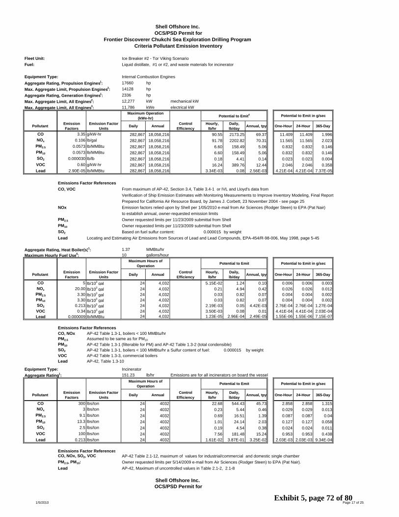
Fleet Unit: Ice Breaker #2 - Tor Viking Scenario
Fuel: Liquid distillate, #1 or #2, and waste materials for incinerator
Equipment Type: Internal Combustion Engines
Aggregate Rating, Propulsion Engines1: 17660 hp
Max. Aggregate Limit, Propulsion Engines2: 14128 hp
Aggregate Rating, Generation Engines1: 2336 hp
Max. Aggregate Limit, All Engines2: 12,277 kW mechanical kW
Max. Aggregate Limit, All Engines3: 11,786 kWe electrical kW
Pollutant Emission Factors
Emission Factor Units Daily Annual Control
EfficiencyHourly,
lb/hr Daily, lb/day Annual, tpy One-Hour 24-Hour 365-Day
CO 3.35 g/kW-hr 282,867 18,058,216 90.55 2173.25 69.37 11.409 11.409 1.996NOx 0.106 lb/gal 282,867 18,058,216 91.78 2202.82 70.31 11.565 11.565 2.023
PM2.5 0.0573 lb/MMBtu 282,867 18,058,216 6.60 158.49 5.06 0.832 0.832 0.146PM10 0.0573 lb/MMBtu 282,867 18,058,216 6.60 158.49 5.06 0.832 0.832 0.146SO2 0.000030 lb/lb 282,867 18,058,216 0.18 4.41 0.14 0.023 0.023 0.004VOC 0.60 g/kW-hr 282,867 18,058,216 16.24 389.76 12.44 2.046 2.046 0.358Lead 2.90E-05 lb/MMBtu 282,867 18,058,216 3.34E-03 0.08 2.56E-03 4.21E-04 4.21E-04 7.37E-05
Emissions Factor ReferencesCO, VOC From maximum of AP-42, Section 3.4, Table 3.4-1 or IVL and Lloyd's data from
Verification of Ship Emission Estimates with Monitoring Measurements to Improve Inventory Modeling, Final Report
Prepared for California Air Resource Board, by James J. Corbett, 23 November 2004 - see page 25
NOx Emission factors relied upon by Shell per 1/05/2010 e-mail from Air Sciences (Rodger Steen) to EPA (Pat Nair)
to establish annual, owner-requested emission limits
PM2.5 Owner requested limits per 11/23/2009 submittal from Shell
PM10 Owner requested limits per 11/23/2009 submittal from Shell
SO2 Based on fuel sulfur content: 0.000015 by weight
Lead Locating and Estimating Air Emissions from Sources of Lead and Lead Compounds, EPA-454/R-98-006, May 1998, page 5-45
Aggregate Rating, Heat Boiler(s)1: 1.37 MMBtu/hr
Maximum Hourly Fuel Use5: 10 gallons/hour
Pollutant Emission Factors
Emission Factor Units Daily Annual Control
EfficiencyHourly,
lb/hr Daily, lb/day Annual, tpy One-Hour 24-Hour 365-Day
CO 5 lb/103 gal 24 4,032 5.15E-02 1.24 0.10 0.006 0.006 0.003NOx 20.00 lb/103 gal 24 4,032 0.21 4.94 0.42 0.026 0.026 0.012
PM2.5 3.30 lb/103 gal 24 4,032 0.03 0.82 0.07 0.004 0.004 0.002PM10 3.30 lb/103 gal 24 4,032 0.03 0.82 0.07 0.004 0.004 0.002SO2 0.213 lb/103 gal 24 4,032 2.19E-03 0.05 4.42E-03 2.76E-04 2.76E-04 1.27E-04VOC 0.34 lb/103 gal 24 4,032 3.50E-03 0.08 0.01 4.41E-04 4.41E-04 2.03E-04Lead 0.000009 lb/MMBtu 24 4,032 1.23E-05 2.96E-04 2.49E-05 1.55E-06 1.55E-06 7.15E-07
Emissions Factor ReferencesCO, NOx AP-42 Table 1.3-1, boilers < 100 MMBtu/hrPM2.5 Assumed to be same as for PM10
PM10 AP-42 Table 1.3-1 (filterable for PM) and AP-42 Table 1.3-2 (total condensible)SO2 AP-42 Table 1.3-1, boilers < 100 MMBtu/hr a Sulfur content of fuel: 0.000015 by weightVOC AP-42 Table 1.3-3, commercial boilers Lead AP-42, Table 1.3-10
Equipment Type: Incinerator
Aggregate Rating1: 151.23 lb/hr Emissions are for all incinerators on board the vessel
Pollutant Emission Factors
Emission Factor Units Daily Annual Control
EfficiencyHourly,
lb/hr Daily, lb/day Annual, tpy One-Hour 24-Hour 365-Day
CO 300 lbs/ton 24 4032 22.68 544.43 45.73 2.858 2.858 1.315NOx 3 lbs/ton 24 4032 0.23 5.44 0.46 0.029 0.029 0.013
PM2.5 9.1 lbs/ton 24 4032 0.69 16.51 1.39 0.087 0.087 0.04PM10 13.3 lbs/ton 24 4032 1.01 24.14 2.03 0.127 0.127 0.058SO2 2.5 lbs/ton 24 4032 0.19 4.54 0.38 0.024 0.024 0.011VOC 100 lbs/ton 24 4032 7.56 181.48 15.24 0.953 0.953 0.438Lead 0.213 lbs/ton 24 4032 1.61E-02 3.87E-01 3.25E-02 2.03E-03 2.03E-03 9.34E-04
Emissions Factor ReferencesCO, NOx, SO2, VOC AP-42 Table 2.1-12, maximum of values for industrial/commercial and domestic single chamber
PM2.5, PM10: Owner requested limits per 5/14/2009 e-mail from Air Sciences (Rodger Steen) to EPA (Pat Nair).
Lead AP-42, Maximum of uncontrolled values in Table 2.1-2, 2.1-8
Shell Offshore Inc. OCS/PSD Permit for
Frontier Discoverer Chukchi Sea Exploration Drilling Program Criteria Pollutant Emission Inventory
Potential to Emit in g/sec
Maximum Hours of Operation Potential to Emit
Maximum Operation (kWe-hr) Potential to Emit4
OCS/PSD Permit for
Potential to Emit Potential to Emit in g/sec
Shell Offshore Inc.
Potential to Emit in g/sec
Maximum Hours of Operation
1/5/2010 Page 17 of 25Exhibit 5, page 72 of 80

Fleet Unit: Ice Breaker #2 - Tor Viking Scenario
(CONTINUED)
Total Emissions for Tor Viking
Hourly, lb/hr
Daily, lb/day Annual, tpy One-Hour 24-Hour 365-Day
113.29 2718.91 115.20 14.274 14.274 3.314
92.22 2213.20 71.19 11.619 11.619 2.048
7.33 175.82 6.52 0.923 0.923 0.187
7.64 183.44 7.16 0.963 0.963 0.206
0.38 9.00 0.53 0.047 0.047 0.015
23.81 571.32 27.69 2.999 2.999 0.7961.95E-02 0.47 3.51E-02 2.45E-03 2.45E-03 1.01E-03
Maximum Emissions for Icebreaker#2 ( max of Tor Viking and Hull 2
Hourly, lb/hr
Daily, lb/day Annual, tpy One-Hour 24-Hour 365-Day
234.48 5627.51 237.17 29.544 29.544 6.822
92.22 2213.20 71.19 11.619 11.619 2.048
11.37 272.87 11.15 1.433 1.433 0.321
11.69 280.49 11.79 1.473 1.473 0.339
0.51 12.19 0.68 0.064 0.064 0.019
23.81 571.32 27.69 2.999 2.999 0.7962.14E-02 0.51 3.73E-02 2.69E-03 2.69E-03 1.07E-03
Conversions Used453.59 g/lb
2,000 lbs/ton
745.7 watts/hp
7.076 lbs/gal
133,098 Btu/gal
Footnotes/Assumptions1 Maximum equipment ratings per Shell submittal to EPA dated 9/17/2009:
Propulsion engines: 17660 hp at maximum
Non-propulsion Generator engines: 2336 hp
Boilers: 1.37 MMBtu/hr
Incinerator: 151.23 lb/hr
2 Maximum operating limit Shell submittal to EPA dated 9/17/2009 (Attachment A, page 23):
80%
3 Minimum generator efficiency based on MaK engine specs per Shell submittal to EPA dated 11/23/2009 (Attachment B, page 14):
Propulsion engine minimum generator efficiency: 96%
4 Fuel usage from AP-42, Section 3.3, brake specific fuel consumption from footnote c to Table 3.3.1
7000 Btu/hp-hr converted based on aggregate engine rating, and fuel density and heat content
Propulsion engines, in aggregate:
Potential to Emit Potential to Emit in g/sec
Frontier Discoverer Chukchi Sea Exploration Drilling Program
Potential to Emit Potential to Emit in g/sec
Criteria Pollutant Emission Inventory
1/5/2010 Page 18 of 25Exhibit 5, page 73 of 80

Fleet Unit: Ice Breaker #2 - Hull 247
Fuel: Liquid distillate, #1 or #2, and waste materials for incinerator
Equipment Type: Internal Combustion Engines
Aggregate Rating, Propulsion Engines1: 24000 kW mechanical kW
Max. Aggregate Limit, Propulsion Engines2: 19200 kW mechanical kW
Max. Aggregate Limit, Propulsion Engines3: 17664 kWe electrical kW
Pollutant Emission Factors
Emission Factor Units Daily Annual Control
EfficiencyHourly,
lb/hr Daily, lb/day Annual, tpy One-Hour 24-Hour 365-Day
CO 5.0 g/kW-hr 423,936 31,904,074 211.64 5,079.48 191.13 26.667 26.667 5.498NOx 1.8 g/kW-hr 423,936 31,904,074 76.19 1,828.61 68.81 9.6 9.6 1.979
PM2.5 0.25 g/kW-hr 423,936 31,904,074 10.58 253.97 9.56 1.333 1.333 0.275PM10 0.25 g/kW-hr 423,936 31,904,074 10.58 253.97 9.56 1.333 1.333 0.275SO2 0.000012 lb/hp-hr 423,936 31,904,074 0.31 7.50 0.28 0.039 0.039 0.008VOC 0.19 g/kW-hr 423,936 31,904,074 8.04 193.02 7.26 1.013 1.013 0.209Lead 2.90E-05 lb/MMBtu 423,936 31,904,074 5.23E-03 0.13 4.72E-03 6.59E-04 6.59E-04 1.36E-04
Emissions Factor ReferencesCO, NOx, PM, VOC Marine engine emission limits in 40 CFR 1042.101 (engines of at least 700 kW). All HC assumed to be VOC
Owner requested annual NOx limits per 9/17/2009 submittal from Shell
PM2.5, PM10 PM2.5 and PM10 emission factors assumed to be same as PM
SO2 AP-42 Table 3.4-1 and Sulfur content of fuel: 0.000015 by weight
Lead Locating and Estimating Air Emissions from Sources of Lead and Lead Compounds, EPA-454/R-98-006, May 1998, page 5-45
Aggregate Rating, Heat Boiler(s)1: 4.00 MMBtu/hr
Maximum Hourly Fuel Use6: 30 gallons/hour
Pollutant Emission Factors
Emission Factor Units Daily Annual Control
EfficiencyHourly,
lb/hr Daily, lb/day Annual, tpy One-Hour 24-Hour 365-Day
CO 5 lb/103 gal 24 4,032 0.15 3.6 0.30 0.019 0.019 0.009NOx 20.00 lb/103 gal 24 4,032 0.60 14.43 1.21 0.076 0.076 0.035
PM2.5 3.30 lb/103 gal 24 4,032 0.10 2.38 0.20 0.012 0.012 0.006PM10 3.30 lb/103 gal 24 4,032 0.10 2.38 0.20 0.012 0.012 0.006SO2 0.213 lb/103 gal 24 4,032 6.40E-03 0.15 0.01 8.07E-04 8.07E-04 3.71E-04VOC 0.34 lb/103 gal 24 4,032 0.01 0.25 0.02 1.29E-03 1.29E-03 5.93E-04Lead 0.000009 lb/MMBtu 24 4,032 3.60E-05 8.64E-04 7.26E-05 4.54E-06 4.54E-06 2.09E-06
Emissions Factor ReferencesCO, NOx AP-42 Table 1.3-1, boilers < 100 MMBtu/hrPM2.5 Assumed to be same as for PM10
PM10 AP-42 Table 1.3-1 (filterable for PM) and AP-42 Table 1.3-2 (total condensible)SO2 AP-42 Table 1.3-1, boilers < 100 MMBtu/hr a Sulfur content of fuel: 0.000015 by weightVOC AP-42 Table 1.3-3, commercial boilers Lead AP-42, Table 1.3-10
Equipment Type: Incinerator
Aggregate Rating1: 151.23 lb/hr Emissions are for all incinerators on board the vessel
Pollutant Emission Factors
Emission Factor Units Daily Annual Control
EfficiencyHourly,
lb/hr Daily, lb/day Annual, tpy One-Hour 24-Hour 365-Day
CO 300 lbs/ton 24 4032 22.68 544.43 45.73 2.858 2.858 1.315NOx 3 lbs/ton 24 4032 0.23 5.44 0.46 0.029 0.029 0.013
PM2.5 9.1 lbs/ton 24 4032 0.69 16.51 1.39 0.087 0.087 0.04PM10 13.3 lbs/ton 24 4032 1.01 24.14 2.03 0.127 0.127 0.058SO2 2.5 lbs/ton 24 4032 0.19 4.54 0.38 0.024 0.024 0.011VOC 100 lbs/ton 24 4032 7.56 181.48 15.24 0.953 0.953 0.438Lead 0.213 lbs/ton 24 4032 1.61E-02 3.87E-01 3.25E-02 2.03E-03 2.03E-03 9.34E-04
Emissions Factor ReferencesCO, NOx, SO2, VOC AP-42 Table 2.1-12, maximum of values for industrial/commercial and domestic single chamber
PM2.5, PM10: Owner requested limits per 5/14/2009 e-mail from Air Sciences (Rodger Steen) to EPA (Pat Nair).
Lead AP-42, Maximum of uncontrolled values in Table 2.1-2, 2.1-8
Maximum Hours of Operation Potential to Emit Potential to Emit in g/sec
Maximum Hours of Operation Potential to Emit Potential to Emit in g/sec
Shell Offshore Inc. OCS/PSD Permit for
Frontier Discoverer Chukchi Sea Exploration Drilling Program Criteria Pollutant Emission Inventory
Maximum Operation (kWe-hr) Potential to Emit4 Potential to Emit in g/sec
1/5/2010 Page 19 of 25Exhibit 5, page 74 of 80

Fleet Unit: Ice Breaker #2 - Hull 247(CONTINUED)
Total Emissions for Hull 247
Hourly, lb/hr
Daily, lb/day Annual, tpy One-Hour 24-Hour 365-Day
234.48 5627.51 237.17 29.544 29.544 6.822
77.02 1848.48 70.48 9.704 9.704 2.027
11.37 272.87 11.15 1.433 1.433 0.321
11.69 280.49 11.79 1.473 1.473 0.339
0.51 12.19 0.68 0.064 0.064 0.019
15.61 374.74 22.52 1.967 1.967 0.6482.14E-02 0.51 3.73E-02 2.69E-03 2.69E-03 1.07E-03
Conversions Used453.59 g/lb
2,000 lbs/ton
745.7 watts/hp
7.076 lbs/gal
133,098 Btu/gal
Footnotes/Assumptions1 Maximum equipment ratings per Shell submittal to EPA dated 9/17/2009 (Attachment A, page 23):
Propulsion engines: 24000 kW mechanical
Non-propulsion Generator engines: 0 hp
Boilers: 4 MMBtu/hr
Incinerator: 151.23 lb/hr
2 Maximum operating limit Shell submittal to EPA dated 9/17/2009 (Attachment A, page 23):
80%
3 Minimum generator efficiency based on Shell submittal to EPA dated 11/23/2009:
Propulsion engine minimum generator efficiency: 92%
4 Fuel usage from AP-42, Section 3.3, brake specific fuel consumption from footnote c to Table 3.3.1
7000 Btu/hp-hr
5 Shell has requested an annual NOx limit of 58.39 tpy per 9/17/2009 submittal
6 Fuel usage converted based on boiler rating and fuel heat content.
Propulsion engines, in aggrega
Shell Offshore Inc. OCS/PSD Permit for
Frontier Discoverer Chukchi Sea Exploration Drilling Program Criteria Pollutant Emission Inventory
Potential to Emit Potential to Emit in g/sec
1/5/2010 Page 20 of 25Exhibit 5, page 75 of 80
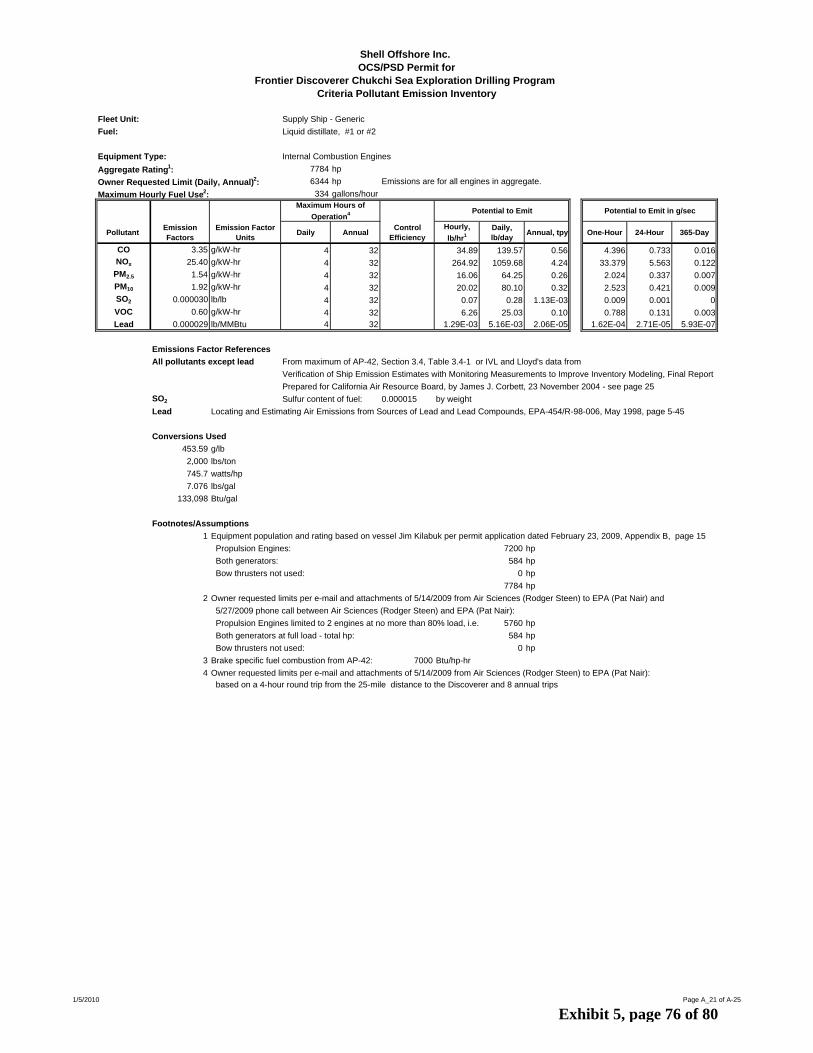
Fleet Unit: Supply Ship - Generic
Fuel: Liquid distillate, #1 or #2
Equipment Type: Internal Combustion Engines
Aggregate Rating1: 7784 hp
Owner Requested Limit (Daily, Annual)2: 6344 hp Emissions are for all engines in aggregate.
Maximum Hourly Fuel Use2: 334 gallons/hour
Pollutant Emission Factors
Emission Factor Units Daily Annual Control
EfficiencyHourly, lb/hr1
Daily, lb/day Annual, tpy One-Hour 24-Hour 365-Day
CO 3.35 g/kW-hr 4 32 34.89 139.57 0.56 4.396 0.733 0.016NOx 25.40 g/kW-hr 4 32 264.92 1059.68 4.24 33.379 5.563 0.122
PM2.5 1.54 g/kW-hr 4 32 16.06 64.25 0.26 2.024 0.337 0.007PM10 1.92 g/kW-hr 4 32 20.02 80.10 0.32 2.523 0.421 0.009SO2 0.000030 lb/lb 4 32 0.07 0.28 1.13E-03 0.009 0.001 0VOC 0.60 g/kW-hr 4 32 6.26 25.03 0.10 0.788 0.131 0.003Lead 0.000029 lb/MMBtu 4 32 1.29E-03 5.16E-03 2.06E-05 1.62E-04 2.71E-05 5.93E-07
Emissions Factor References
All pollutants except lead From maximum of AP-42, Section 3.4, Table 3.4-1 or IVL and Lloyd's data from
Verification of Ship Emission Estimates with Monitoring Measurements to Improve Inventory Modeling, Final Report
Prepared for California Air Resource Board, by James J. Corbett, 23 November 2004 - see page 25
SO2 Sulfur content of fuel: 0.000015 by weight
Lead Locating and Estimating Air Emissions from Sources of Lead and Lead Compounds, EPA-454/R-98-006, May 1998, page 5-45
Conversions Used453.59 g/lb
2,000 lbs/ton
745.7 watts/hp
7.076 lbs/gal
133,098 Btu/gal
Footnotes/Assumptions1 Equipment population and rating based on vessel Jim Kilabuk per permit application dated February 23, 2009, Appendix B, page 15
Propulsion Engines: 7200 hp
Both generators: 584 hp
Bow thrusters not used: 0 hp
7784 hp
2 Owner requested limits per e-mail and attachments of 5/14/2009 from Air Sciences (Rodger Steen) to EPA (Pat Nair) and
5/27/2009 phone call between Air Sciences (Rodger Steen) and EPA (Pat Nair):
Propulsion Engines limited to 2 engines at no more than 80% load, i.e. 5760 hp
Both generators at full load - total hp: 584 hp
Bow thrusters not used: 0 hp
3 Brake specific fuel combustion from AP-42: 7000 Btu/hp-hr
4 Owner requested limits per e-mail and attachments of 5/14/2009 from Air Sciences (Rodger Steen) to EPA (Pat Nair): based on a 4-hour round trip from the 25-mile distance to the Discoverer and 8 annual trips
Potential to Emit in g/secMaximum Hours of
Operation4 Potential to Emit
Shell Offshore Inc. OCS/PSD Permit for
Frontier Discoverer Chukchi Sea Exploration Drilling Program Criteria Pollutant Emission Inventory
1/5/2010 Page A_21 of A-25
Exhibit 5, page 76 of 80

Fleet Unit: Oil Spill Response Main Ship - Nanuq
Fuel: Liquid distillate, #1 or #2, and waste materials for incinerator
Equipment Type: Propulsion Engines - Caterpillar 3608 Internal Combustion Engines
Aggregate Rating1: 5420 kW
Pollutant Emission Factors Emission Factor Units Daily Annual
Control Efficiency5, 6
Hourly, lb/hr3
Daily, lb/day Annual, tpy One-Hour 24-Hour 365-Day
CO 0.73 g/kW-hr 3,000 504,000 0.9 0.87 7.57 0.64 0.11 0.04 0.018NOx 13.62 g/kW-hr 3,000 504,000 162.70 1412.02 118.61 20.5 7.413 3.412
PM2.5 0.17 g/kW-hr 3,000 504,000 0.85 0.30 2.64 0.22 0.038 0.014 0.006PM10 0.17 g/kW-hr 3,000 504,000 0.85 0.30 2.64 0.22 0.038 0.014 0.006
SO22,4 0.000030 lb/lb fuel 3,000 504,000 0.07 0.64 0.05 0.009 0.003 0.00
VOC 0.99 g/kW-hr 3,000 504,000 0.9 1.18 10.27 0.86 0.149 0.054 0.025Lead 0.000029 lb/MMBtu 3,000 504,000 1.33E-03 1.16E-02 9.73E-04 1.68E-04 6.08E-05 2.80E-05
Emissions Factor ReferencesCO, NOx, PM2.5, PM10, VOC Permit application dated February 23, 2009, Appendix B, page 51
NOx NOx emission factor was converted from NO to NO2, ra 1.53
SO2 Sulfur content of fuel: 0.000015 by weight
Lead Locating and Estimating Air Emissions from Sources of Lead and Lead Compounds, EPA-454/R-98-006, May 1998, page 5-45
Equipment Type: Non-Propulsion Generator Engines
Aggregate Rating1: 2570 hp
Owner Requested Limit (Daily, Annual)2: 800 gal/day
Pollutant Emission Factors Emission Factor Units Daily Annual
Control Efficiency5, 6
Hourly, lb/hr
Daily, lb/day Annual, tpy One-Hour 24-Hour 365-Day
CO 3.35 g/kW-hr 800 134,400 0.9 1.41 8.37 0.70 0.178 0.044 0.02NOx 25.40 g/kW-hr 800 134,400 107.32 635.21 53.36 13.522 3.335 1.535
PM2.5 1.54 g/kW-hr 800 134,400 0.85 0.98 5.78 0.49 0.123 0.03 0.014PM10 1.92 g/kW-hr 800 134,400 0.85 1.22 7.20 0.60 0.153 0.038 0.017SO2 0.000030 lb/lb fuel 800 134,400 2.87E-02 1.70E-01 1.43E-02 0.004 0.001 0.00VOC 0.60 g/kW-hr 800 134,400 0.9 0.25 1.50 0.13 0.032 0.008 0.004Lead 0.000029 lb/MMBtu 800 134,400 5.22E-04 3.09E-03 2.59E-04 6.57E-05 1.62E-05 7.46E-06
Emissions Factor ReferencesAll pollutants except lead From maximum of AP-42, Section 3.4, Table 3.4-1 or IVL and Lloyd's data from
and SO2 Verification of Ship Emission Estimates with Monitoring Measurements to Improve Inventory Modeling, Final Report
Prepared for California Air Resource Board, by James J. Corbett, 23 November 2004 - see page 25
SO2 Sulfur content of fuel: 0.000015 by weight
Lead Locating and Estimating Air Emissions from Sources of Lead and Lead Compounds, EPA-454/R-98-006, May 1998, page 5-45
Equipment Type: Incinerator
Aggregate Rating1: 125.00 lb/hr Emissions are for all incinerators on board the vessel
Pollutant Emission Factors Emission Factor Units Daily Annual Control
EfficiencyHourly,
lb/hr Daily, lb/day Annual, tpy One-Hour 24-Hour 365-Day
CO 300 lbs/ton 24 4,032 18.75 450.00 37.80 2.362 2.362 1.087NOx 3 lbs/ton 24 4,032 0.19 4.50 0.38 0.024 0.024 0.011
PM2.5 9.1 lbs/ton 24 4,032 0.57 13.65 1.15 0.072 0.072 0.033PM10 13.3 lbs/ton 24 4,032 0.83 19.95 1.68 0.105 0.105 0.048SO2 2.5 lbs/ton 24 4,032 0.16 3.75 0.32 0.02 0.02 0.01VOC 100 lbs/ton 24 4,032 6.25 150.00 12.60 0.787 0.787 0.362Lead 0.213 lbs/ton 24 4,032 0.01 0.32 2.68E-02 1.68E-03 1.68E-03 7.72E-04
Emissions Factor ReferencesCO, NOx, SO2, VOC AP-42 Table 2.1-12, maximum of values for industrial/commercial and domestic single chamber
PM2.5, PM10 Owner requested limits e-mail and attachments of 5/14/2009 from Air Sciences (Rodger Steen) to EPA (Pat Nair).
Lead AP-42, Maximum of uncontrolled values in Table 2.1-2, 2.1-8
Conversions Used453.59 g/lb
2,000 lbs/ton
745.7 watts/hp
7.076 lbs/gal
133,098 Btu/gal
Shell Offshore Inc. OCS/PSD Permit for
Frontier Discoverer Chukchi Sea Exploration Drilling Program Criteria Pollutant Emission Inventory
Potential to Emit in g/sec
Maximum Hours of Operation
Potential to Emit in g/sec
Potential to Emit in g/secPotential to Emit
Maximum Operation (gallons)2 Potential to Emit
Maximum Operation (gallons)2 Potential to Emit
1/5/2010 Page A-22 of A-25Exhibit 5, page 77 of 80

Fleet Unit: Oil Spill Response Main Ship - Nanuq
(CONTINUED)
Footnotes/Assumptions1 Equipment population, rating and usage based on vessel Nanuq per permit application dated February 23, 2009, Appendix B, page 16
Hourly emissions are based on the aggregate rating of all equipment on board except for the emergency generator
2 Owner requested limits per e-mail and attachments of 5/14/2009 from Air Sciences (Rodger Steen) to EPA (Pat Nair), and
Shell's updated request dated 9/17/2009:
Propulsion Engines expected to not exceed (in aggregate): 47000 kW-hr/day
Maximum fuel usage: 3000 gal/day
Generator usage expected to not exceed (in aggregate): 11,350 kW-hr/day
Maximum fuel usage: 800 gal/day
3 Fuel usage per permit application dated 2/23/2009, Appendix B, page 51 204.7 g/kW-hr
4 Fuel usage from AP-42, Section 3.3, brake specific fuel consumption from footnote c to Table 3.3.1
7000 Btu/hp-hr converted based on aggregate engine rating, and fuel density and heat content
5 PM10 control efficiency based on California Air Resources Board, Verification of Diesel Emission Control Strategies, 3/12/2009 (website),April 24, 2009 letter from CleanAIR Systems and April 20, 2007 quote from CleanAIR Systems, transmitted by April 27, 2009 e-mail from Air Sciences (Rodger Steen) to EPA (Pat Nair)
6 CO and VOC control efficiency from April 24, 2009 letter from CleanAIR Systems and April 20, 2007 quote from CleanAIR Systems,
Frontier Discoverer Chukchi Sea Exploration Drilling Program Criteria Pollutant Emission Inventory
Shell Offshore Inc. OCS/PSD Permit for
1/5/2010 Page A-23 of A-25Exhibit 5, page 78 of 80

Fleet Unit: Oil Spill Response, Kvichak 34-foot No. 1, 2 and 3 Work Boats (three)
Fuel: Liquid distillate, #1 or #2
Equipment Type: Internal Combustion Engines - propulsion
Make/Model1: Cummins QSB Aggregate Rating1: 1800 hp Emissions are for all Cummins QSB engines
Pollutant Emission Factors
Emission Factor Units Daily Annual Control
EfficiencyHourly,
lb/hr Daily, lb/day Annual, tpy One-Hour 24-Hour 365-Day
CO 0.155 g/hp-hr 24 4,032 0.62 15 1.24 0.078 0.078 0.036NOx 4.644 g/hp-hr 24 4,032 18.43 442 37.15 2.322 2.322 1.069
PM2.5 0.077 g/hp-hr 24 4,032 0.31 7 0.62 0.039 0.039 0.018PM10 0.077 g/hp-hr 24 4,032 0.31 7 0.62 0.039 0.039 0.018SO2 0.000030 lb/lb fuel 24 4,032 0.02 0 0.04 0.003 0.003 0.001VOC 0.078 g/hp-hr 24 4,032 0.31 7 0.62 0.039 0.039 0.018Lead 0.000029 lb/MMBtu 24 4,032 3.65E-04 0.01 7.37E-04 4.60E-05 4.604E-05 2.12E-05
Emissions Factor ReferencesCO, NOx, PM2.5, PM10, VOC From permit application dated February 23, 2009, Appendix B, page 64
PM2.5 and PM10 emissions assumed to be same as PM emissions
Lead Locating and Estimating Air Emissions from Sources of Lead and Lead Compounds, EPA-454/R-98-006, May 1998, page 5-45
Equipment Type: Internal Combustion Engines - generators
Aggregate Rating1: 36 hp Emissions are for all generator engines
Pollutant Emission Factors
Emission Factor Units Daily Annual Control
EfficiencyHourly,
lb/hr Daily, lb/day Annual, tpy One-Hour 24-Hour 365-Day
CO 0.95 lb/MMBtu 24 4,032 0.24 6 0.48 0.03 0.03 0.014NOx 4.410 lb/MMBtu 24 4,032 1.11 27 2.24 0.14 0.14 0.064
PM2.5 0.31 lb/MMBtu 24 4,032 0.08 2 0.16 0.01 0.01 0.005PM10 0.31 lb/MMBtu 24 4,032 0.08 2 0.16 0.01 0.01 0.005SO2 0.000030 lb/lb fuel 24 4,032 4.02E-04 1.00E-02 8.10E-04 0 0 0VOC 0.35 lb/MMBtu 24 4,032 0.09 2 0.18 0.011 0.011 0.005Lead 0.000029 lb/MMBtu 24 4,032 7.31E-06 1.75E-04 1.47E-05 9.21E-07 9.208E-07 4.24E-07
Emissions Factor ReferencesCO, NOx, PM2.5, PM10, VOC From AP-42, Section 3.3, Table 3.3-1
Lead Locating and Estimating Air Emissions from Sources of Lead and Lead Compounds, EPA-454/R-98-006, May 1998, page 5-45
Conversions Used453.59 g/lb
2,000 lbs/ton
745.7 watts/hp
7.076 lbs/gal
133,098 Btu/gal
Footnotes/Assumptions1 Equipment population, rating and usage based on 3 work boats per permit application dated February 23, 2009, Appendix B,
pages 16, 67 - Each of three identical Kvichak 34-foot boats has two 305 hp propulsion engines and a 12 hp generator
2 7000 Btu/hp-hr converted based on aggregate engine rating, and fuel density and heat content
3 Sulfur content of fuel: 0.000015 by weight
Potential to Emit in g/sec
Maximum Hours of Operation Potential to Emit
Maximum Hours of Operation Potential to Emit
Potential to Emit in g/sec
Shell Offshore Inc. OCS/PSD Permit for
Frontier Discoverer Chukchi Sea Exploration Drilling Program Criteria Pollutant Emission Inventory
1/5/2010 Page A-24 of A-25Exhibit 5, page 79 of 80

Fuel heat value:
133,098 Btu/gal
Fuel density: 847.9 kg/m3 SCANRAFF-Vladimir Ignatjuk Certificate of Quality. 09/19/04.7.076 lbs/gal converted based on 453.59 g/lb and
264.17 gal/m3
Detroit 8V71N
Detroit 3V-71 John Deere John Deere
Caterpillar C7
Caterpillar C7
Pollutant
Emission Factors
cont. (g/hp-hr)
Emission Factors
cont. (g/hp-hr)
Emission Factors,
cont. (g/kW-hr)
Emission Factors,
cont. (g/hp-hr)
Emission Factors, cont.
(g/kW-hr)
Emission Factors,
uncont. (g/hp-hr)
Maximum Emission
Factor
Emission Factor Units
CO 0.299 0.66 0.55 0.41 0.70 0.52 0.66 g/hp-hrNOx 9.81 11.72 7.5 5.59 4.0 2.98 11.72 g/hp-hr
PM2.5 0.19 0.29 0.09 0.07 0.03 0.02 0.29 g/hp-hrPM10 0.19 0.29 0.09 0.07 0.03 0.02 0.29 g/hp-hrVOC 0.148 0.20 0.75 0.56 4.0 2.98 2.98 g/hp-hr
SO2 emissions not compared as they are based on mass balance
AP-42 Maximum
Section 3.4 IVL Lloyd's EFPollutant lb/hp-hr g/kW-hr g/kW-hr g/kW-hr g/kW-hr
CO 5.50E-03 3.35 1.4 1.6 3.35
NOx5 0.056 25.40 18.1 17 25.40
PM2.5 0.00056 0.34 1.54 1.54PM10 0.00058 0.35 1.92 1.5 1.92
SO25 1.2135E-05 0.01 0 0.798 0.80
VOC 0.000705 0.43 0.6 0.5 0.60
AP_42 MaximumMarine Engine
Marine Engine Section 1.3 EF
EF EF1Tables 1 to
3Pollutant g/kW-hr lb/103 gal lb/103 gal lb/103 gal
CO 3.35 104.58 5 104.58
NOx5 25.40 794.01 20.00 794.01
PM2.5 1.54 48.14 3.30 48.14PM10 1.92 60.02 3.30 60.02
SO25 0.80 24.94 26.98 26.98
VOC 0.60 18.76 0.34 18.76
1 Conversions based on 745.7 watts/hp453.59 g/lb
Brake specific fuel consumption: 7000 Btu/hp-hr
Reference Table 4Comparison of Emission Factors for
Marine Engines and External Combustion
Comparison of Controlled Emission Factors for Cementing Units and Logging Winches
Comparison of Emission Factors for Marine EnginesReference Table 3
Fuel Properties for Distillate Fuel Used on All Emission Units on the DiscovererReference Table 1
Keiser, Ronald email to Chris Tengco, 01/26/09, see permit application dated February 23, 2009, Appendix F, page 27.
Reference Table 2
Shell Offshore Inc. OCS/PSD Permit for
Frontier Discoverer Chukchi Sea Exploration Drilling Program Criteria Pollutant Emission Inventory
1/5/2010 Page 25 of 25
Exhibit 5, page 80 of 80