Embed Size (px)
Citation preview
High Efficiency Electric Power Generation; The Environmental Role János Beér Massachusetts Institute of Technology Cambridge, MA 02139 USA
Abstract Electric power generation system development is reviewed with special attention to plant efficiency. While higher efficiency is well understood to be economically beneficial because of fuel savings, its effect upon reduction of all plant emissions without installation of additional environmental equipment, is less well appreciated. As CO2 emission control is gaining increasing acceptance,efficiency improvement, as the only practical tool capable of reducing CO2 emission from fossil fuel plant in the short term, has become a key concept for the choice of technology for new plant and upgrades of existing plant. Efficiency is also important for longer term solutions of reducing CO2 emission by carbon capture and sequestration (CCS); it is essential for the underlying plants to be highly efficient so as to mitigate the energy penalty of CCS technology application. Power generating options,including coal fired Rankine cycle steam plants with advanced steam parameters , natural gas fired Gas Turbine-Steam, and Coal Gasification Combined Cycle plants are discussed and compared for their efficiency, cost and operational availability. Special attention is paid to the timeline of the various technologies for their development, demonstration and commercial availability for deployment. A. Introduction Efficiency (η%), the electric energy output as a fraction of the fuel energy input of a thermal power plant is usually expressed in percentages. Another parameter used for determining efficiency is the Heat Rate (HR), the fuel energy input required for the generation of unit of electricity (Btu/kWh), or (kJ/kWh). Generation efficiency (η%) is 3600 (kJ/kWh) divided by HR (kJ/kWh) x100, or 3414 Btu/kWh divided by HR (Btu/kWh)x100. The fuel energy input can be entered into the calculation either by the higher (gross) or by the lower(net) heating value of the fuel (HHV or LHV); but when comparing the efficiency of different energy conversion systems, it is important to ensure that the same type of heating value is used. HHV is the heating value directly determined by calorimetric measurement in the laboratory. In this measurement, the fuel is combusted in a closed vessel, and the heat of combustion is transferred to water that surrounds the calorimeter. The combustion products are cooled to 60ºF (15ºC) and hence, the heat of condensation of the water vapor originating from the combustion of hydrogen, and from the evaporation of the coal moisture, is included in the measured heating value. For determining the lower heating value, LHV, calculation is needed to deduct the heat of condensation from the HHV. In US engineering practice, HHV is generally used for steam plants, while in the European practice, efficiency calculations are based on LHV. For Gas turbine cycles, LHV is used both in the US and Europe. Perhaps one reason for this difference in the method of calculating steam power plant efficiencies is that US electric utilities purchase coal
on a $/MBtu (HHV) basis and want to know their efficiency also on that basis, while the European practice is based on the realization that the heat of condensation is not a recoverable part of the fuel’s energy, because it is not practicable to cool sulfur bearing flue gas to below its dew point in the boiler. LHV can be calculated by using the International Energy Agency (IEA) formula as: LHV=HHV-(91.14xH + 10.32xH2O +0.35xO), where LHV and HHV are in Btu/lb, and H, H2O and O are in %, on “as received” basis. [1], or in SI units as: LHV=HHV-(0.2121xH + 0.02442xH2O + 0.0008xO, where LHV and HHV are in MJ/kg, and H, H2O and O are in %. For better comparisons with non US data, unless specifically stated, LHV based efficiency values are given in the following discussion. Reference is made often to changes in efficiency by percentage points, which should be distinguished from relative changes in percentage; for example, a change by two percentage points from 40 to 42% is a relative change of 5%. The difference in efficiency between HHV and LHV for bituminous coal is about 2 percentage points absolute (5% relative), but for high-moisture subbituminous coals and lignites the difference is about 3-4 percentage points (>8% relative). The average efficiency of US installed coal based electricity generating plant is about 34% (LHV). Advanced cycles of power generation, some of which are mature technologies, others, at the stage of R&D or demonstration, promise to generate electricity at significantly higher efficiency, up to 50% (LHV). Higher efficiency which is presently the practical route to mitigating CO2 emission is also key to the reduction of all emissions. In the near and medium term, there are several options for clean and more efficient electric power generation including the following technologies: Advanced Rankine Cycle Plants • Pulverized coal combustion in Supercritical steam boiler (PC/SC) with steam parameters:
245 bar, 565/565/565°C (1050/1050/1050°F) • Pulverized coal combustion in Ultra Supercritical steam boiler (PC/USC) with steam
parameters: 300 bar 600/600°C, (4350 psi,1100/1100°F), • Ultra supercritical steam (PC/USC) 375 bar, 700/720°C (5440psi, 1292/1328°F) • Circulating Fluidized Bed Combustion (CFBC) in Supercritical steam boiler Brayton-Rankine Combined Cycle Plants • Natural Gas Combined Cycle (NGCC) • Pressurized Fluidized Bed (PFBC) with Topping Combustion Cycle (TC) • Integrated Gasification Combined Cycle (IGCC) • Hybrid Gasification/Fuel Cell/GT/Steam Cycle (DOE’s Vision21 Cycle) Carbon Capture&Sequestration (CCS) capable plants • IGCC with CO2 capture and compression • PC/SC with Oxy-Flue gas recirculation (O2/FGR) • CFBC with O2 /FGR • Coal Gasification with Chemical and Thermal Looping
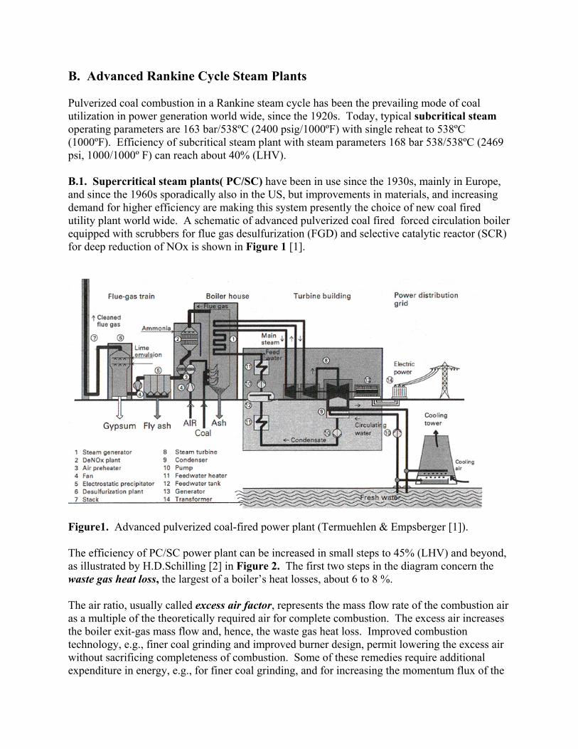
B. Advanced Rankine Cycle Steam Plants Pulverized coal combustion in a Rankine steam cycle has been the prevailing mode of coal utilization in power generation world wide, since the 1920s. Today, typical subcritical steam operating parameters are 163 bar/538ºC (2400 psig/1000ºF) with single reheat to 538ºC (1000ºF). Efficiency of subcritical steam plant with steam parameters 168 bar 538/538ºC (2469 psi, 1000/1000º F) can reach about 40% (LHV). B.1. Supercritical steam plants( PC/SC) have been in use since the 1930s, mainly in Europe, and since the 1960s sporadically also in the US, but improvements in materials, and increasing demand for higher efficiency are making this system presently the choice of new coal fired utility plant world wide. A schematic of advanced pulverized coal fired forced circulation boiler equipped with scrubbers for flue gas desulfurization (FGD) and selective catalytic reactor (SCR) for deep reduction of NOx is shown in Figure 1 [1].
Figure1. Advanced pulverized coal-fired power plant (Termuehlen & Empsberger [1]). The efficiency of PC/SC power plant can be increased in small steps to 45% (LHV) and beyond, as illustrated by H.D.Schilling [2] in Figure 2. The first two steps in the diagram concern the waste gas heat loss, the largest of a boiler’s heat losses, about 6 to 8 %. The air ratio, usually called excess air factor, represents the mass flow rate of the combustion air as a multiple of the theoretically required air for complete combustion. The excess air increases the boiler exit-gas mass flow and, hence, the waste gas heat loss. Improved combustion technology, e.g., finer coal grinding and improved burner design, permit lowering the excess air without sacrificing completeness of combustion. Some of these remedies require additional expenditure in energy, e.g., for finer coal grinding, and for increasing the momentum flux of the
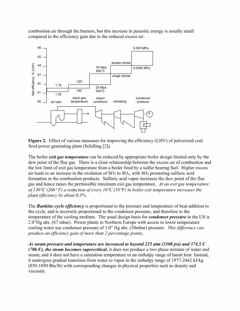
combustion air through the burners, but this increase in parasitic energy is usually small compared to the efficiency gain due to the reduced excess air.
Figure 2. Effect of various measures for improving the efficiency (LHV) of pulverized coal fired power generating plant (Schilling [2]). The boiler exit gas temperature can be reduced by appropriate boiler design limited only by the dew point of the flue gas. There is a close relationship between the excess air of combustion and the low limit of exit gas temperature from a boiler fired by a sulfur bearing fuel. Higher excess air leads to an increase in the oxidation of SO2 to SO3, with SO3 promoting sulfuric acid formation in the combustion products. Sulfuric acid vapor increases the dew point of the flue gas and hence raises the permissible minimum exit gas temperature. At an exit gas temperature of 130°C (266° F) a reduction of every 10°C (18°F) in boiler exit temperature increases the plant efficiency by about 0.3%. The Rankine cycle efficiency is proportional to the pressure and temperature of heat addition to the cycle, and is inversely proportional to the condenser pressure, and therefore to the temperature of the cooling medium. The usual design basis for condenser pressure in the US is 2.0”Hg abs. (67 mbar). Power plants in Northern Europe with access to lower temperature cooling water use condenser pressure of 1.0” Hg abs. (30mbar) pressure. This difference can produce an efficiency gain of more than 2 percentage points. As steam pressure and temperature are increased to beyond 225 atm (3308 psi) and 374.5 C (706 F), the steam becomes supercritical, it does not produce a two phase mixture of water and steam, and it does not have a saturation temperature or an enthalpy range of latent heat. Instead, it undergoes gradual transition from water to vapor in the enthalpy range of 1977-2442 kJ/kg (850-1050 Btu/lb) with corresponding changes in physical properties such as density and viscosity.
Net
effi
cien
cy, %
(LH
V)
40
41
42
43
44
45
46
air ratio stack gas
temperature steam
conditions reheating condenser pressure
G
1.15
1.25
120°
130°
30 Mpa 600°C
25 Mpa 540°C
double reheat
single reheat
0.003 MPa
0.0065 MPa
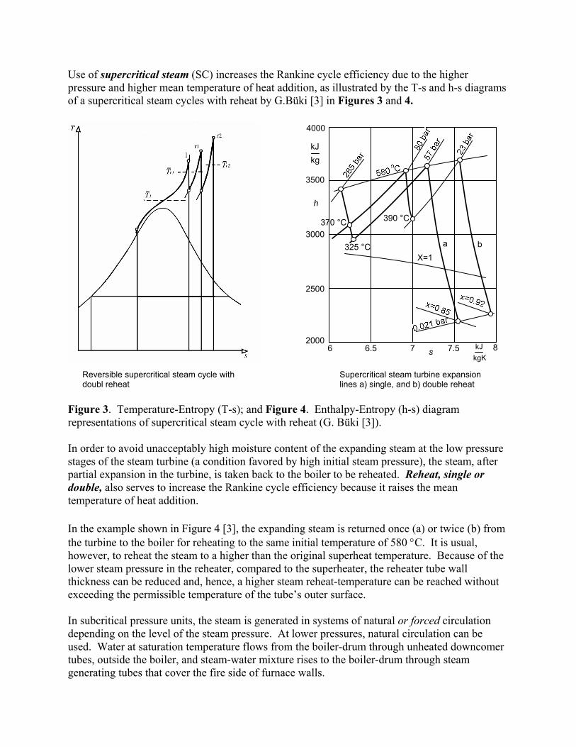
Use of supercritical steam (SC) increases the Rankine cycle efficiency due to the higher pressure and higher mean temperature of heat addition, as illustrated by the T-s and h-s diagrams of a supercritical steam cycles with reheat by G.Büki [3] in Figures 3 and 4.
Figure 3. Temperature-Entropy (T-s); and Figure 4. Enthalpy-Entropy (h-s) diagram representations of supercritical steam cycle with reheat (G. Büki [3]). In order to avoid unacceptably high moisture content of the expanding steam at the low pressure stages of the steam turbine (a condition favored by high initial steam pressure), the steam, after partial expansion in the turbine, is taken back to the boiler to be reheated. Reheat, single or double, also serves to increase the Rankine cycle efficiency because it raises the mean temperature of heat addition. In the example shown in Figure 4 [3], the expanding steam is returned once (a) or twice (b) from the turbine to the boiler for reheating to the same initial temperature of 580 °C. It is usual, however, to reheat the steam to a higher than the original superheat temperature. Because of the lower steam pressure in the reheater, compared to the superheater, the reheater tube wall thickness can be reduced and, hence, a higher steam reheat-temperature can be reached without exceeding the permissible temperature of the tube’s outer surface. In subcritical pressure units, the steam is generated in systems of natural or forced circulation depending on the level of the steam pressure. At lower pressures, natural circulation can be used. Water at saturation temperature flows from the boiler-drum through unheated downcomer tubes, outside the boiler, and steam-water mixture rises to the boiler-drum through steam generating tubes that cover the fire side of furnace walls.
2000
2500
3000
3500
4000
6 6.5 7 7.5 8
h
kJ kg
390 °C
325 °C
370 °C
a b
kJ kgK
X=1
s
Reversible supercritical steam cycle with doubl reheat
Supercritical steam turbine expansion lines a) single, and b) double reheat
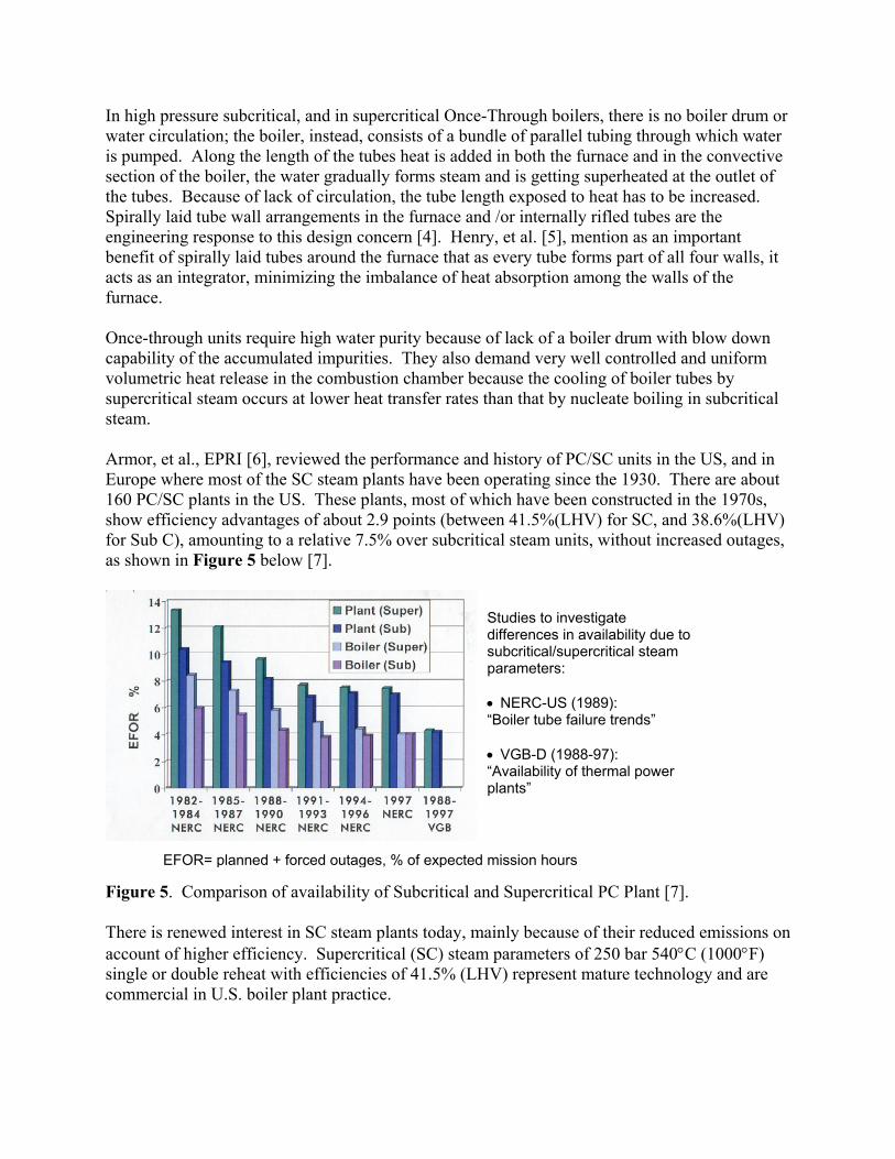
In high pressure subcritical, and in supercritical Once-Through boilers, there is no boiler drum or water circulation; the boiler, instead, consists of a bundle of parallel tubing through which water is pumped. Along the length of the tubes heat is added in both the furnace and in the convective section of the boiler, the water gradually forms steam and is getting superheated at the outlet of the tubes. Because of lack of circulation, the tube length exposed to heat has to be increased. Spirally laid tube wall arrangements in the furnace and /or internally rifled tubes are the engineering response to this design concern [4]. Henry, et al. [5], mention as an important benefit of spirally laid tubes around the furnace that as every tube forms part of all four walls, it acts as an integrator, minimizing the imbalance of heat absorption among the walls of the furnace. Once-through units require high water purity because of lack of a boiler drum with blow down capability of the accumulated impurities. They also demand very well controlled and uniform volumetric heat release in the combustion chamber because the cooling of boiler tubes by supercritical steam occurs at lower heat transfer rates than that by nucleate boiling in subcritical steam. Armor, et al., EPRI [6], reviewed the performance and history of PC/SC units in the US, and in Europe where most of the SC steam plants have been operating since the 1930. There are about 160 PC/SC plants in the US. These plants, most of which have been constructed in the 1970s, show efficiency advantages of about 2.9 points (between 41.5%(LHV) for SC, and 38.6%(LHV) for Sub C), amounting to a relative 7.5% over subcritical steam units, without increased outages, as shown in Figure 5 below [7].
Figure 5. Comparison of availability of Subcritical and Supercritical PC Plant [7]. There is renewed interest in SC steam plants today, mainly because of their reduced emissions on account of higher efficiency. Supercritical (SC) steam parameters of 250 bar 540°C (1000°F) single or double reheat with efficiencies of 41.5% (LHV) represent mature technology and are commercial in U.S. boiler plant practice.
Studies to investigate differences in availability due to subcritical/supercritical steam parameters: • NERC-US (1989): “Boiler tube failure trends” • VGB-D (1988-97): “Availability of thermal power plants”
EFOR= planned + forced outages, % of expected mission hours
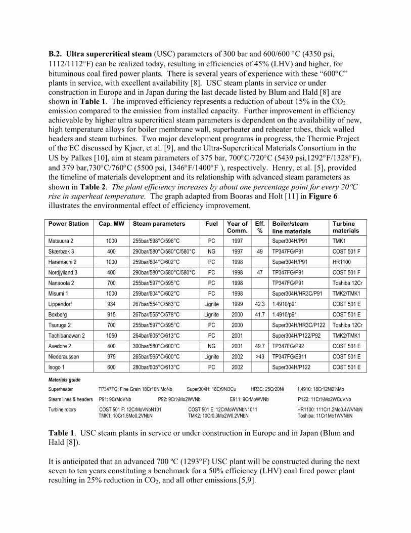
B.2. Ultra supercritical steam (USC) parameters of 300 bar and 600/600 °C (4350 psi, 1112/1112°F) can be realized today, resulting in efficiencies of 45% (LHV) and higher, for bituminous coal fired power plants. There is several years of experience with these “600°C” plants in service, with excellent availability [8]. USC steam plants in service or under construction in Europe and in Japan during the last decade listed by Blum and Hald [8] are shown in Table 1. The improved efficiency represents a reduction of about 15% in the CO2 emission compared to the emission from installed capacity. Further improvement in efficiency achievable by higher ultra supercritical steam parameters is dependent on the availability of new, high temperature alloys for boiler membrane wall, superheater and reheater tubes, thick walled headers and steam turbines. Two major development programs in progress, the Thermie Project of the EC discussed by Kjaer, et al. [9], and the Ultra-Supercritical Materials Consortium in the US by Palkes [10], aim at steam parameters of 375 bar, 700°C/720°C (5439 psi,1292°F/1328°F), and 379 bar,730°C/760°C (5500 psi, 1346°F/1400°F ), respectively. Henry, et al. [5], provided the timeline of materials development and its relationship with advanced steam parameters as shown in Table 2. The plant efficiency increases by about one percentage point for every 20°C rise in superheat temperature. The graph adapted from Booras and Holt [11] in Figure 6 illustrates the environmental effect of efficiency improvement. Power Station Cap. MW Steam parameters Fuel Year of
Comm. Eff. %
Boiler/steam line materials
Turbine materials
Matsuura 2 1000 255bar/598°C/596°C PC 1997 Super304H/P91 TMK1 Skærbæk 3 400 290bar/580°C/580°C/580°C NG 1997 49 TP347FG/P91 COST 501 F Haramachi 2 1000 259bar/604°C/602°C PC 1998 Super304H/P91 HR1100 Nordjyiland 3 400 290bar/580°C/580°C/580°C PC 1998 47 TP347FG/P91 COST 501 F Nanaoota 2 700 255bar/597°C/595°C PC 1998 TP347FG/P91 Toshiba 12Cr Misumi 1 1000 259bar/604°C/602°C PC 1998 Super304H/HR3C/P91 TMK2/TMK1 Lippendorf 934 267bar/554°C/583°C Lignite 1999 42.3 1.4910/p91 COST 501 E Boxberg 915 267bar/555°C/578°C Lignite 2000 41.7 1.4910/p91 COST 501 E Tsuruga 2 700 255bar/597°C/595°C PC 2000 Super304H/HR3C/P122 Toshiba 12Cr Tachibanawan 2 1050 264bar/605°C/613°C PC 2001 Super304H/P122/P92 TMK2/TMK1 Avedore 2 400 300bar/580°C/600°C NG 2001 49.7 TP347FG/P92 COST 501 E Niederaussen 975 265bar/565°C/600°C Lignite 2002 >43 TP347FG/E911 COST 501 E Isogo 1 600 280bar/605°C/613°C PC 2002 Super304H/P122 COST 501 E
Materials guide Superheater TP347FG: Fine Grain 18Cr10NiMoNb Super304H: 18Cr9Ni3Cu HR3C: 25Cr20Ni 1,4910: 18Cr12Ni2½Mo
Steam lines & headers P91: 9CrMoVNb P92: 9Cr½Mo2WVNb E911: 9CrMoWVNb P122: 11Cr½Mo2WCuVNb
Turbine rotors COST 501 F: 12CrMoVNbN101 COST 501 E: 12CrMoWVNbN1011 HR1100: 111Cr1.2Mo0.4WVNbN TMK1: 10Cr1.5Mo0.2VNbN TMK2: 10Cr0.3Mo2W0.2VNbN Toshiba: 11Cr1Mo1WVNbN Table 1. USC steam plants in service or under construction in Europe and in Japan (Blum and Hald [8]). It is anticipated that an advanced 700 ºC (1293°F) USC plant will be constructed during the next seven to ten years constituting a benchmark for a 50% efficiency (LHV) coal fired power plant resulting in 25% reduction in CO2, and all other emissions.[5,9].
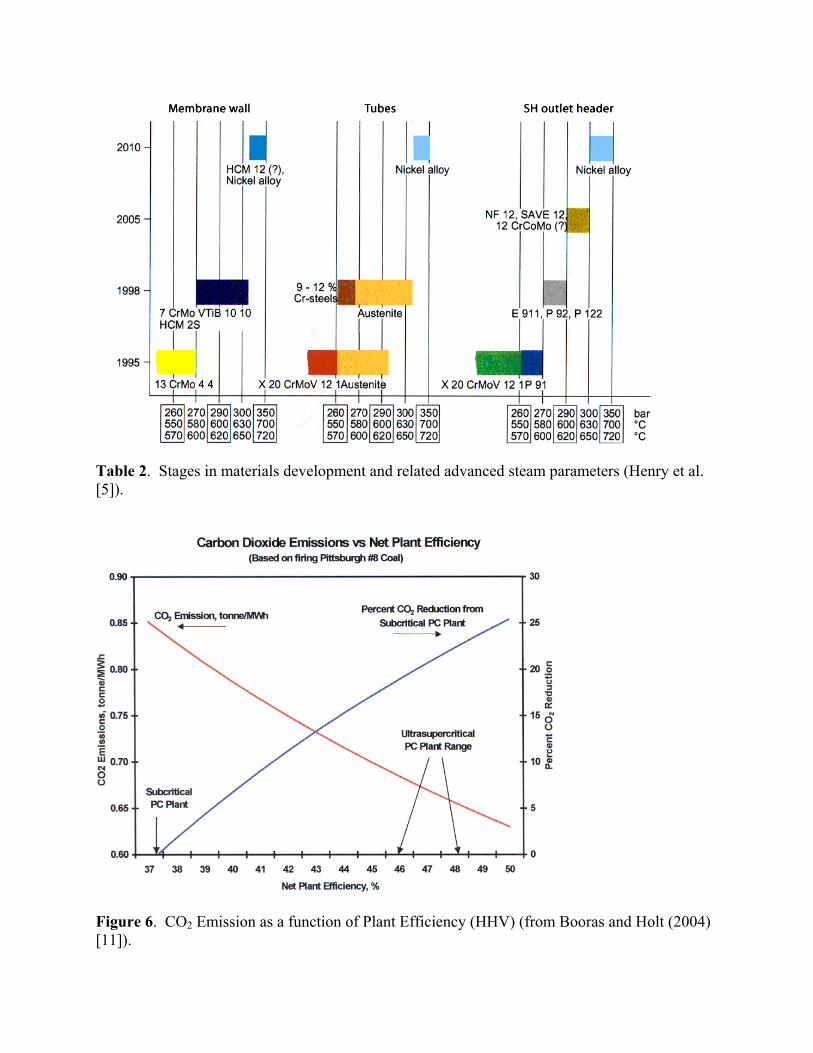
Table 2. Stages in materials development and related advanced steam parameters (Henry et al. [5]).
Figure 6. CO2 Emission as a function of Plant Efficiency (HHV) (from Booras and Holt (2004) [11]).
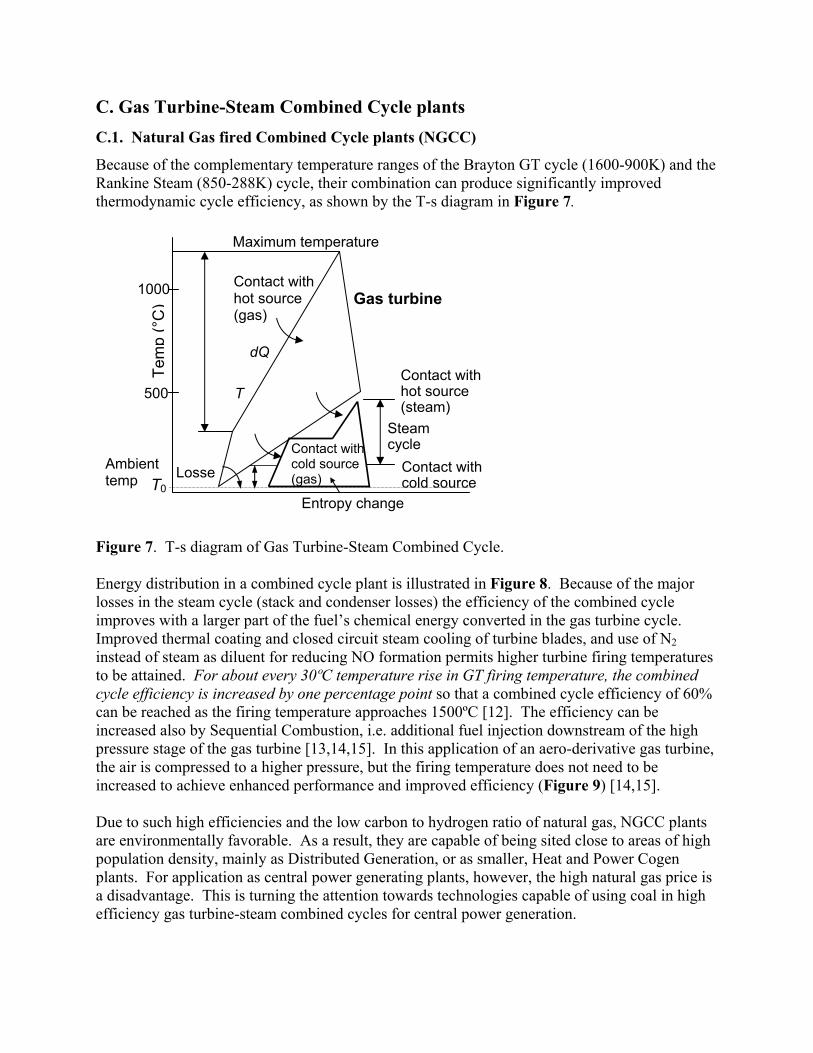
C. Gas Turbine-Steam Combined Cycle plants C.1. Natural Gas fired Combined Cycle plants (NGCC)
Because of the complementary temperature ranges of the Brayton GT cycle (1600-900K) and the Rankine Steam (850-288K) cycle, their combination can produce significantly improved thermodynamic cycle efficiency, as shown by the T-s diagram in Figure 7.
Figure 7. T-s diagram of Gas Turbine-Steam Combined Cycle. Energy distribution in a combined cycle plant is illustrated in Figure 8. Because of the major losses in the steam cycle (stack and condenser losses) the efficiency of the combined cycle improves with a larger part of the fuel’s chemical energy converted in the gas turbine cycle. Improved thermal coating and closed circuit steam cooling of turbine blades, and use of N2 instead of steam as diluent for reducing NO formation permits higher turbine firing temperatures to be attained. For about every 30ºC temperature rise in GT firing temperature, the combined cycle efficiency is increased by one percentage point so that a combined cycle efficiency of 60% can be reached as the firing temperature approaches 1500ºC [12]. The efficiency can be increased also by Sequential Combustion, i.e. additional fuel injection downstream of the high pressure stage of the gas turbine [13,14,15]. In this application of an aero-derivative gas turbine, the air is compressed to a higher pressure, but the firing temperature does not need to be increased to achieve enhanced performance and improved efficiency (Figure 9) [14,15]. Due to such high efficiencies and the low carbon to hydrogen ratio of natural gas, NGCC plants are environmentally favorable. As a result, they are capable of being sited close to areas of high population density, mainly as Distributed Generation, or as smaller, Heat and Power Cogen plants. For application as central power generating plants, however, the high natural gas price is a disadvantage. This is turning the attention towards technologies capable of using coal in high efficiency gas turbine-steam combined cycles for central power generation.
Gas turbine
Maximum temperature
Contact with hot source (gas)
Contact with cold source (gas)
Contact with cold source
Contact with hot source (steam)
Steam cycle
Ambient temp Losse
dQ
T
1000
500
Tem
p (°
C)
T0 Entropy change
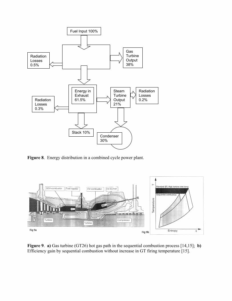
Figure 8. Energy distribution in a combined cycle power plant.
Figure 9. a) Gas turbine (GT26) hot gas path in the sequential combustion process [14,15]; b) Efficiency gain by sequential combustion without increase in GT firing temperature [15].
Fuel Input 100%
Gas Turbine Output 38%
Radiation Losses 0.5%
Radiation Losses 0.3%
Steam Turbine Output 21%
Radiation Losses 0.2%
Energy in Exhaust 61.5%
Stack 10% Condenser 30%
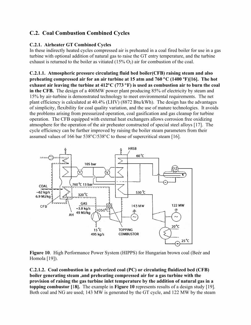
C.2. Coal Combustion Combined Cycles C.2.1. Airheater GT Combined Cycles In these indirectly heated cycles compressed air is preheated in a coal fired boiler for use in a gas turbine with optional addition of natural gas to raise the GT entry temperature, and the turbine exhaust is returned to the boiler as vitiated (15% O2) air for combustion of the coal. C.2.1.1. Atmospheric pressure circulating fluid bed boiler(CFB) raising steam and also preheating compressed air for an air turbine at 15 atm and 760 °C (1400 ºF)[16]. The hot exhaust air leaving the turbine at 412°C (773 °F) is used as combustion air to burn the coal in the CFB. The design of a 400MW power plant producing 85% of electricity by steam and 15% by air-turbine is demonstrated technology to meet environmental requirements. The net plant efficiency is calculated at 40.4% (LHV) (8872 Btu/kWh). The design has the advantages of simplicity, flexibility for coal quality variation, and the use of mature technologies. It avoids the problems arising from pressurized operation, coal gasification and gas cleanup for turbine operation. The CFB equipped with external heat exchangers allows corrosion free oxidizing atmosphere for the operation of the air preheater constructed of special steel alloys [17]. The cycle efficiency can be further improved by raising the boiler steam parameters from their assumed values of 166 bar 538°C/538°C to those of supercritical steam [16].
Figure 10. High Performance Power System (HIPPS) for Hungarian brown coal (Beér and Homola [19]). C.2.1.2. Coal combustion in a pulverized coal (PC) or circulating fluidized bed (CFB) boiler generating steam ,and preheating compressed air for a gas turbine with the provision of raising the gas turbine inlet temperature by the addition of natural gas in a topping combustor [18]. The example in Figure 10 represents results of a design study [19]. Both coal and NG are used; 143 MW is generated by the GT cycle, and 122 MW by the steam
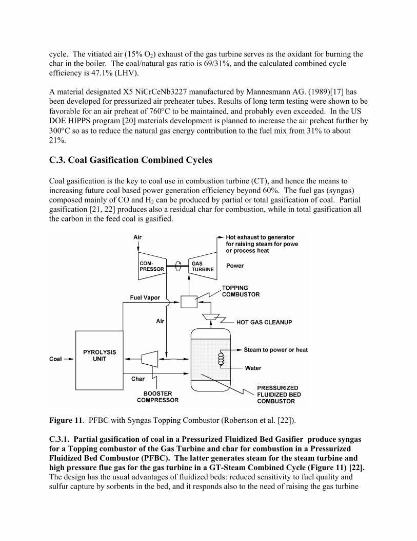
cycle. The vitiated air (15% O2) exhaust of the gas turbine serves as the oxidant for burning the char in the boiler. The coal/natural gas ratio is 69/31%, and the calculated combined cycle efficiency is 47.1% (LHV). A material designated X5 NiCrCeNb3227 manufactured by Mannesmann AG. (1989)[17] has been developed for pressurized air preheater tubes. Results of long term testing were shown to be favorable for an air preheat of 760°C to be maintained, and probably even exceeded. In the US DOE HIPPS program [20] materials development is planned to increase the air preheat further by 300°C so as to reduce the natural gas energy contribution to the fuel mix from 31% to about 21%. C.3. Coal Gasification Combined Cycles Coal gasification is the key to coal use in combustion turbine (CT), and hence the means to increasing future coal based power generation efficiency beyond 60%. The fuel gas (syngas) composed mainly of CO and H2 can be produced by partial or total gasification of coal. Partial gasification [21, 22] produces also a residual char for combustion, while in total gasification all the carbon in the feed coal is gasified.
Figure 11. PFBC with Syngas Topping Combustor (Robertson et al. [22]). C.3.1. Partial gasification of coal in a Pressurized Fluidized Bed Gasifier produce syngas for a Topping combustor of the Gas Turbine and char for combustion in a Pressurized Fluidized Bed Combustor (PFBC). The latter generates steam for the steam turbine and high pressure flue gas for the gas turbine in a GT-Steam Combined Cycle (Figure 11) [22]. The design has the usual advantages of fluidized beds: reduced sensitivity to fuel quality and sulfur capture by sorbents in the bed, and it responds also to the need of raising the gas turbine
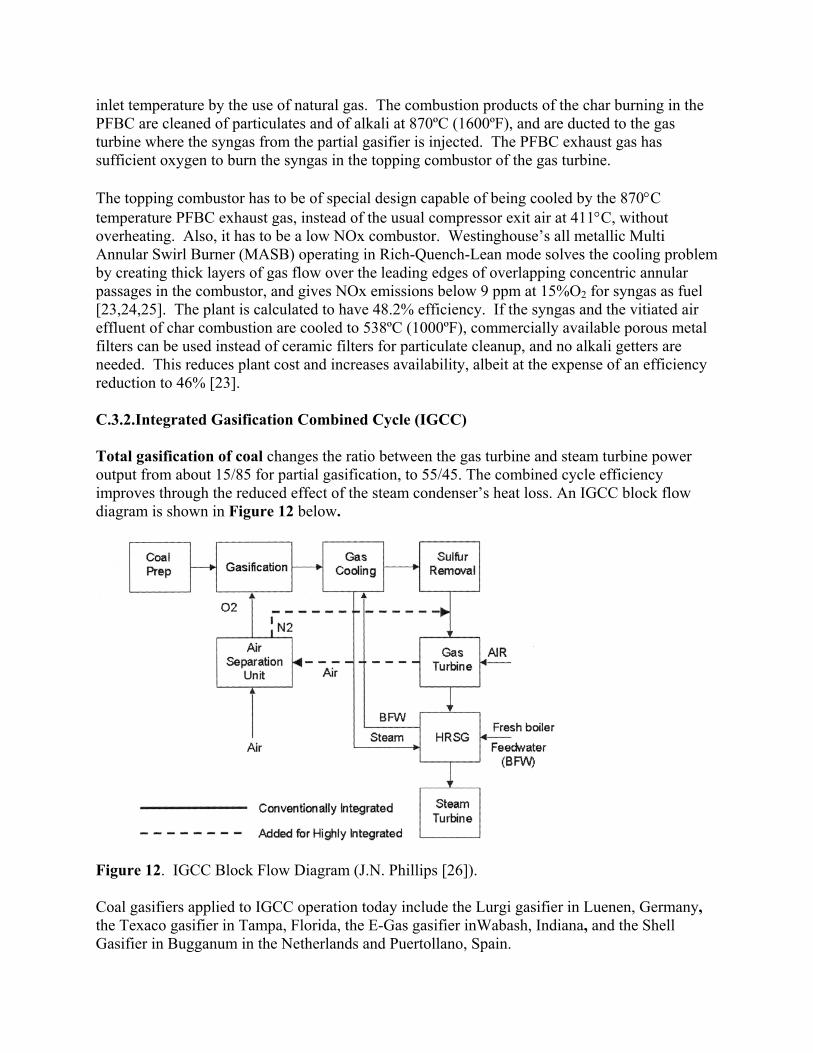
inlet temperature by the use of natural gas. The combustion products of the char burning in the PFBC are cleaned of particulates and of alkali at 870ºC (1600ºF), and are ducted to the gas turbine where the syngas from the partial gasifier is injected. The PFBC exhaust gas has sufficient oxygen to burn the syngas in the topping combustor of the gas turbine. The topping combustor has to be of special design capable of being cooled by the 870°C temperature PFBC exhaust gas, instead of the usual compressor exit air at 411°C, without overheating. Also, it has to be a low NOx combustor. Westinghouse’s all metallic Multi Annular Swirl Burner (MASB) operating in Rich-Quench-Lean mode solves the cooling problem by creating thick layers of gas flow over the leading edges of overlapping concentric annular passages in the combustor, and gives NOx emissions below 9 ppm at 15%O2 for syngas as fuel [23,24,25]. The plant is calculated to have 48.2% efficiency. If the syngas and the vitiated air effluent of char combustion are cooled to 538ºC (1000ºF), commercially available porous metal filters can be used instead of ceramic filters for particulate cleanup, and no alkali getters are needed. This reduces plant cost and increases availability, albeit at the expense of an efficiency reduction to 46% [23]. C.3.2.Integrated Gasification Combined Cycle (IGCC) Total gasification of coal changes the ratio between the gas turbine and steam turbine power output from about 15/85 for partial gasification, to 55/45. The combined cycle efficiency improves through the reduced effect of the steam condenser’s heat loss. An IGCC block flow diagram is shown in Figure 12 below.
Figure 12. IGCC Block Flow Diagram (J.N. Phillips [26]). Coal gasifiers applied to IGCC operation today include the Lurgi gasifier in Luenen, Germany, the Texaco gasifier in Tampa, Florida, the E-Gas gasifier inWabash, Indiana, and the Shell Gasifier in Bugganum in the Netherlands and Puertollano, Spain.
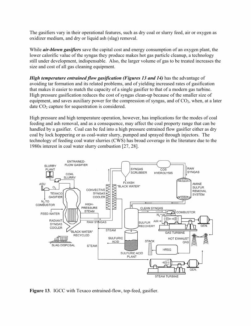
The gasifiers vary in their operational features, such as dry coal or slurry feed, air or oxygen as oxidizer medium, and dry or liquid ash (slag) removal. While air-blown gasifiers save the capital cost and energy consumption of an oxygen plant, the lower calorific value of the syngas they produce makes hot gas particle cleanup, a technology still under development, indispensable. Also, the larger volume of gas to be treated increases the size and cost of all gas cleaning equipment. High temperature entrained flow gasification (Figures 13 and 14) has the advantage of avoiding tar formation and its related problems, and of yielding increased rates of gasification that makes it easier to match the capacity of a single gasifier to that of a modern gas turbine. High pressure gasification reduces the cost of syngas clean-up because of the smaller size of equipment, and saves auxiliary power for the compression of syngas, and of CO2, when, at a later date CO2 capture for sequestration is considered. High pressure and high temperature operation, however, has implications for the modes of coal feeding and ash removal, and as a consequence, may affect the coal property range that can be handled by a gasifier. Coal can be fed into a high pressure entrained flow gasifier either as dry coal by lock hoppering or as coal-water slurry, pumped and sprayed through injectors. The technology of feeding coal water slurries (CWS) has broad coverage in the literature due to the 1980s interest in coal water slurry combustion [27, 28].
Figure 13. IGCC with Texaco entrained-flow, top-feed, gasifier.
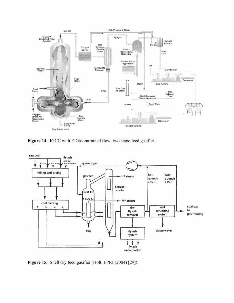
Figure 14. IGCC with E-Gas entrained flow, two stage feed gasifier.
Figure 15. Shell dry feed gasifier (Holt, EPRI (2004) [29]).
Dry coal feed gasifiers (e.g., Shell, Figure 15) are more appropriate for low rank, high moisture coals. High moisture coals, however, have to be predried in preparation for lock hoppering and pneumatic conveying. This leads to energy penalty because of reduced steam turbine output due to the present practice of steam-drying. A dry feed pump system (Stamet pump) is under development in the US DOE IGCC RD&D Program [30]. It promises reduced cost, coal feed without lock hoppers and improvement of plant efficiency by about 0.5 percentage points. Slurry feeding (GE-Texaco, Conoco-Phillips) does not require lock hoppers because the coal-water slurry is an incompressible fluid that can be pumped to the burners of a pressurized gasifier. There is about 35% water in the slurry of a high quality bituminous coal. The water content of the slurry varies with coal type and more strongly with particle size fineness; as the coal is ground more finely, more water is needed to maintain sufficiently low viscosity for trouble free slurry transportation. Slurry viscosity can be reduced also by additives that make the coal more hydrophilic [27]. Because of its high initial water content, slurry feed does not lend itself well for gasification of high moisture coals. Dry or liquid ash (slag) removal Physical and chemical transformations of coal ash upon heating are discussed by Reid [31]. Most coal ash samples show initial deformation and become sticky at around 1100°C and melt at 1300-1400°C. These temperatures depend on the chemical composition of the ash and are somewhat higher for oxidizing, than for reducing conditions. The fouling of convective heat exchange surfaces, e.g., Syngas cooler, by semi-molten ash deposited is a major cause of forced plant outage. By increasing the operating temperature of the gasifier to beyond the melting point of the ash, up to 90% of the coal ash can be removed in liquid form (slag), significantly reducing thereby the mass flow rate of ash liable to forming deposits in convective heat exchangers. Conditions for reaching the elevated temperatures required for liquid ash removal include coal of high heating value, coal ash with favorable melting-viscosity characteristics, and sufficiently high oxygen concentration of the feed stream. For low rank and /or high ash (low heating value) coals more oxygen has to be used to reach the temperature required for reducing the slag viscosity to the 250 to 300 poise range, required for trouble free slag removal. The technology of liquid slag removal and slag heat recovery is dicussed in detail by Dolezal [32, 33]. Gasifier design has effect on the ease of slag removal and on high pressure operation. In the Texaco gasifier with top coal-oxygen feed (Fig. 13), the maximum flame temperature is in the region close to the top, while the slag tap is at the bottom of the gasifier, where the gas temperature is lower due to heat extraction along the path down the gasifier. As the temperature is raised on the top to ensure that the molten slag flows through the taphole, care has to be taken not to damage the refractory lining of the gasifier. In the two-stage design of the E-Gas gasifier (Fig.14), the first stage coal-oxygen feed-stream creates a sufficiently high temperature zone right above the slag tap enabling fluid slag removal for a wider range of coal types and ash qualities. Gasifier refractory lining. Gasifiers are either refractory lined or have membrane walls cooled by steam. The slurry fed gasifiers (Texaco, E-Gas) are refractory lined which is one of the factors that limits their availability and require a spare gasifier for higher than 80% capacity factor operation. Research
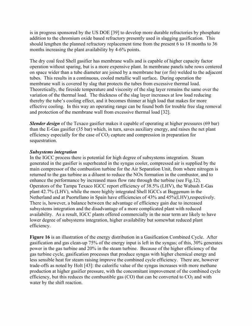
is in progress sponsored by the US DOE [39] to develop more durable refractories by phosphate addition to the chromium oxide based refractory presently used in slagging gasification. This should lengthen the planned refractory replacement time from the present 6 to 18 months to 36 months increasing the plant availability by 4-6% points. The dry coal feed Shell gasifier has membrane walls and is capable of higher capacity factor operation without sparing, but is a more expensive plant. In membrane panels tube rows centered on space wider than a tube diameter are joined by a membrane bar (or fin) welded to the adjacent tubes. This results in a continuous, cooled metallic wall surface. During operation the membrane wall is covered by slag that protects the tubes from excessive thermal load. Theoretically, the fireside temperature and viscosity of the slag layer remains the same over the variation of the thermal load. The thickness of the slag layer increases at low load reducing thereby the tube’s cooling effect, and it becomes thinner at high load that makes for more effective cooling. In this way an operating range can be found both for trouble free slag removal and protection of the membrane wall from excessive thermal load [32]. Slender design of the Texaco gasifier makes it capable of operating at higher pressures (69 bar) than the E-Gas gasifier (35 bar) which, in turn, saves auxiliary energy, and raises the net plant efficiency especially for the case of CO2 capture and compression in preparation for sequestration. Subsystems integration In the IGCC process there is potential for high degree of subsystems integration. Steam generated in the gasifier is superheated in the syngas cooler, compressed air is supplied by the main compressor of the combustion turbine for the Air Separation Unit, from where nitrogen is returned to the gas turbine as a diluent to reduce the NOx formation in the combustor, and to enhance the performance by increased mass flow rate through the turbine (see Fig.12). Operators of the Tampa Texaco IGCC report efficiency of 38.5% (LHV), the Wabash E-Gas plant 42.7% (LHV), while the more highly integrated Shell IGCCs at Buggenum in the Netherland and at Puortellano in Spain have efficiencies of 43% and 45%(LHV),respectively. There is, however, a balance between the advantage of efficiency gain due to increased subsystems integration and the disadvantage of a more complicated plant with reduced availability. As a result, IGCC plants offered commercially in the near term are likely to have lower degree of subsystems integration, higher availability but somewhat reduced plant efficiency. Figure 16 is an illustration of the energy distribution in a Gasification Combined Cycle. After gasification and gas clean-up 75% of the energy input is left in the syngas; of this, 30% generates power in the gas turbine and 20% in the steam turbine. Because of the higher efficiency of the gas turbine cycle, gasification processes that produce syngas with higher chemical energy and less sensible heat for steam raising improve the combined cycle efficiency. There are, however trade-offs as noted by Holt [43]: the calorific value of the syngas increases with more methane production at higher gasifier pressure, with the concomitant improvement of the combined cycle efficiency, but this reduces the combustible gas (CO) that can be converted to CO2 and with water by the shift reaction.
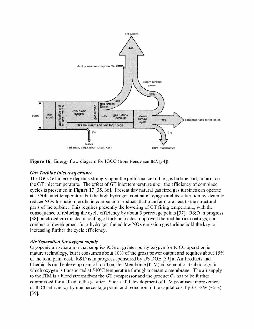
Figure 16. Energy flow diagram for IGCC (from Henderson IEA [34]). Gas Turbine inlet temperature The IGCC efficiency depends strongly upon the performance of the gas turbine and, in turn, on the GT inlet temperature. The effect of GT inlet temperature upon the efficiency of combined cycles is presented in Figure 17 [35, 36]. Present day natural gas fired gas turbines can operate at 1550K inlet temperature but the high hydrogen content of syngas and its saturation by steam to reduce NOx formation results in combustion products that transfer more heat to the structural parts of the turbine. This requires presently the lowering of GT firing temperature, with the consequence of reducing the cycle efficiency by about 3 percetage points [37]. R&D in progress [38] on closed circuit steam cooling of turbine blades, improved thermal barrier coatings, and combustor development for a hydrogen fueled low NOx emission gas turbine hold the key to increasing further the cycle efficiency. Air Separation for oxygen supply Cryogenic air separation that supplies 95% or greater purity oxygen for IGCC operation is mature technology, but it consumes about 10% of the gross power output and requires about 15% of the total plant cost. R&D is in progress sponsored by US DOE [39] at Air Products and Chemicals on the development of Ion Transfer Membrane (ITM) air separation technology, in which oxygen is transported at 540ºC temperature through a ceramic membrane. The air supply to the ITM is a bleed stream from the GT compressor and the product O2 has to be further compressed for its feed to the gasifier. Successful development of ITM promises improvement of IGCC efficiency by one percentage point, and reduction of the capital cost by $75/kW (~5%) [39].
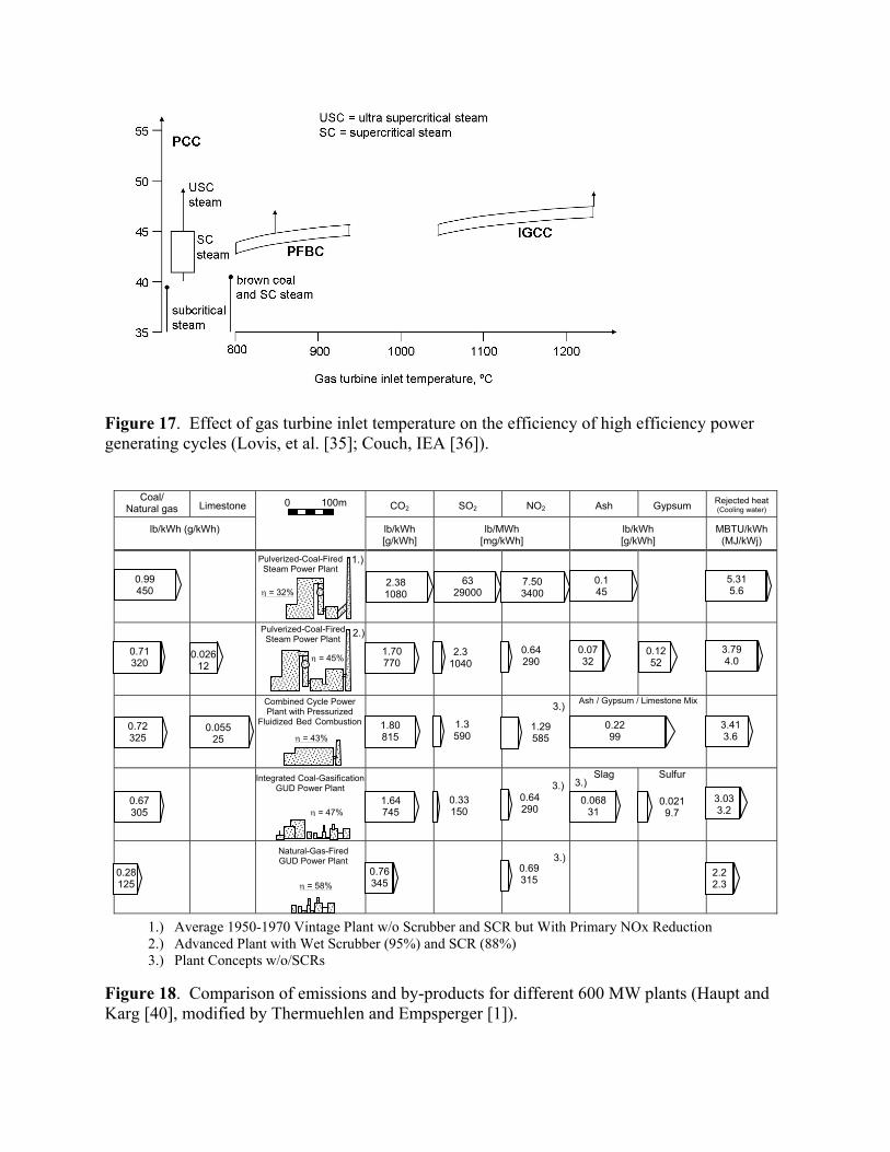
Figure 17. Effect of gas turbine inlet temperature on the efficiency of high efficiency power generating cycles (Lovis, et al. [35]; Couch, IEA [36]).
Coal/
Natural gas Limestone CO2 SO2 NO2 Ash Gypsum Rejected heat (Cooling water)
lb/kWh (g/kWh)
lb/kWh [g/kWh]
lb/MWh [mg/kWh]
lb/kWh [g/kWh]
MBTU/kWh (MJ/kWj)
Ash / Gypsum / Limestone Mix
Slag Sulfur
1.) Average 1950-1970 Vintage Plant w/o Scrubber and SCR but With Primary NOx Reduction 2.) Advanced Plant with Wet Scrubber (95%) and SCR (88%) 3.) Plant Concepts w/o/SCRs
Figure 18. Comparison of emissions and by-products for different 600 MW plants (Haupt and Karg [40], modified by Thermuehlen and Empsperger [1]).
Pulverized-Coal-Fired Steam Power Plant
Combined Cycle Power Plant with Pressurized
Fluidized Bed Combustion
Integrated Coal-Gasification GUD Power Plant
Natural-Gas-Fired GUD Power Plant
η = 58%
η = 47%
η = 43%
η = 45% 0.026 12
0.71 320
0.72 325
0.99 450
0.67 305
0.28 125
0.055 25
Pulverized-Coal-Fired Steam Power Plant
η = 32% 2.38 1080
1.70 770
1.80 815
1.64 745
0.76 345
63 29000
7.50 3400
0.1 45
5.31 5.6
2.3 1040
1.3 590
0.33 150
0.64 290
0.69 315
1.29 585
0.64 290
0.068 31
0.22 99
0.07 32
0.12 52
0.021 9.7
3.79 4.0
3.41 3.6
3.03 3.2
2.2 2.3
0 100m
1.)
2.)
3.)
3.) 3.)
3.)
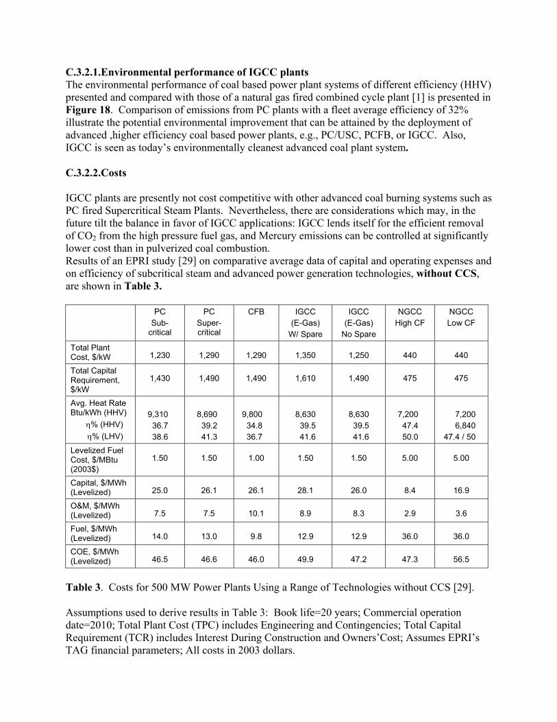
C.3.2.1.Environmental performance of IGCC plants The environmental performance of coal based power plant systems of different efficiency (HHV) presented and compared with those of a natural gas fired combined cycle plant [1] is presented in Figure 18. Comparison of emissions from PC plants with a fleet average efficiency of 32% illustrate the potential environmental improvement that can be attained by the deployment of advanced ,higher efficiency coal based power plants, e.g., PC/USC, PCFB, or IGCC. Also, IGCC is seen as today’s environmentally cleanest advanced coal plant system. C.3.2.2.Costs IGCC plants are presently not cost competitive with other advanced coal burning systems such as PC fired Supercritical Steam Plants. Nevertheless, there are considerations which may, in the future tilt the balance in favor of IGCC applications: IGCC lends itself for the efficient removal of CO2 from the high pressure fuel gas, and Mercury emissions can be controlled at significantly lower cost than in pulverized coal combustion. Results of an EPRI study [29] on comparative average data of capital and operating expenses and on efficiency of subcritical steam and advanced power generation technologies, without CCS, are shown in Table 3. PC
Sub-critical
PC Super-critical
CFB
IGCC (E-Gas)
W/ Spare
IGCC (E-Gas)
No Spare
NGCC High CF
NGCC Low CF
Total Plant Cost, $/kW
1,230
1,290
1,290
1,350
1,250
440
440
Total Capital Requirement, $/kW
1,430
1,490
1,490
1,610
1,490
475
475
Avg. Heat Rate Btu/kWh (HHV)
η% (HHV) η% (LHV)
9,310 36.7 38.6
8,690 39.2 41.3
9,800 34.8 36.7
8,630 39.5 41.6
8,630 39.5 41.6
7,200 47.4 50.0
7,200 6,840
47.4 / 50 Levelized Fuel Cost, $/MBtu (2003$)
1.50
1.50
1.00
1.50
1.50
5.00
5.00
Capital, $/MWh (Levelized)
25.0
26.1
26.1
28.1
26.0
8.4
16.9
O&M, $/MWh (Levelized)
7.5
7.5
10.1
8.9
8.3
2.9
3.6
Fuel, $/MWh (Levelized)
14.0
13.0
9.8
12.9
12.9
36.0
36.0
COE, $/MWh (Levelized)
46.5
46.6
46.0
49.9
47.2
47.3
56.5
Table 3. Costs for 500 MW Power Plants Using a Range of Technologies without CCS [29]. Assumptions used to derive results in Table 3: Book life=20 years; Commercial operation date=2010; Total Plant Cost (TPC) includes Engineering and Contingencies; Total Capital Requirement (TCR) includes Interest During Construction and Owners’Cost; Assumes EPRI’s TAG financial parameters; All costs in 2003 dollars.
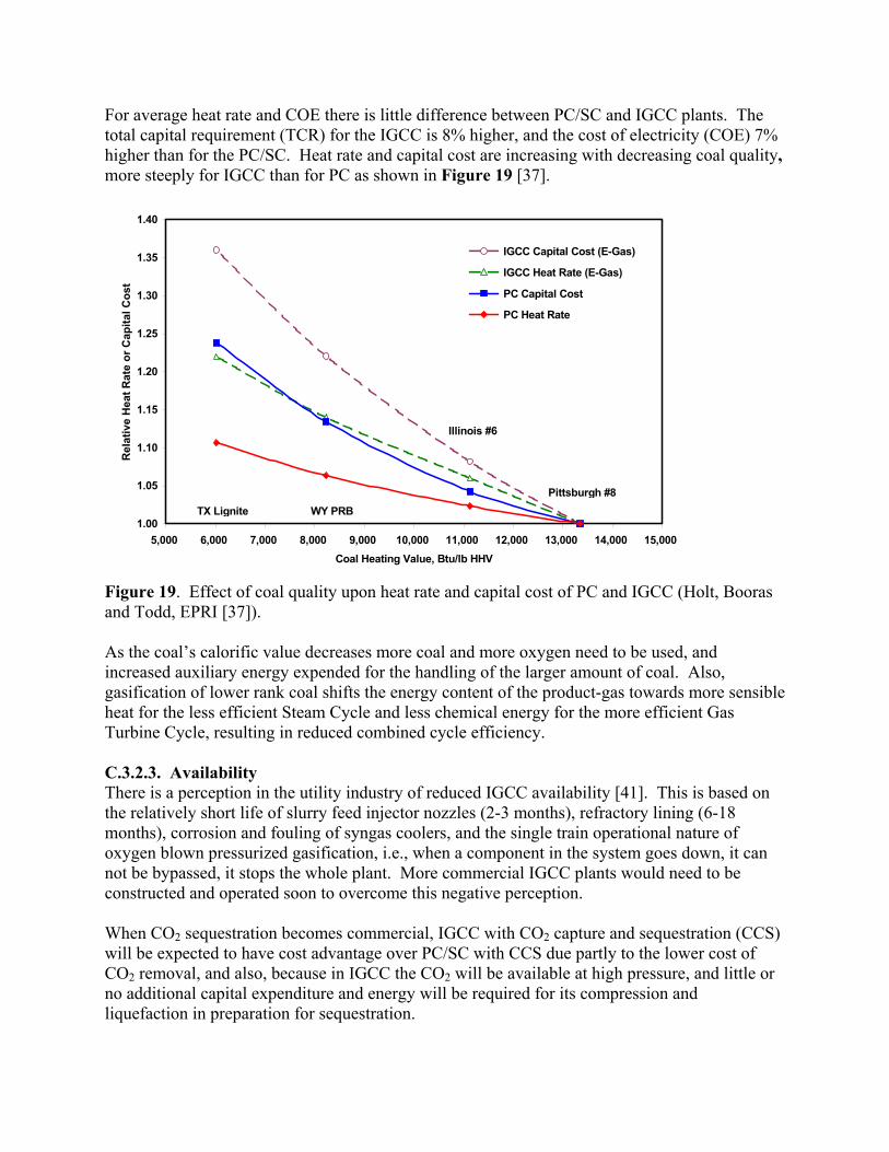
For average heat rate and COE there is little difference between PC/SC and IGCC plants. The total capital requirement (TCR) for the IGCC is 8% higher, and the cost of electricity (COE) 7% higher than for the PC/SC. Heat rate and capital cost are increasing with decreasing coal quality, more steeply for IGCC than for PC as shown in Figure 19 [37].
1.00
1.05
1.10
1.15
1.20
1.25
1.30
1.35
1.40
5,000 6,000 7,000 8,000 9,000 10,000 11,000 12,000 13,000 14,000 15,000Coal Heating Value, Btu/lb HHV
Rel
ativ
e H
eat R
ate
or C
apita
l Cos
t
IGCC Capital Cost (E-Gas)
IGCC Heat Rate (E-Gas)
PC Capital Cost
PC Heat Rate
WY PRBTX Lignite
Illinois #6
Pittsburgh #8
Figure 19. Effect of coal quality upon heat rate and capital cost of PC and IGCC (Holt, Booras and Todd, EPRI [37]). As the coal’s calorific value decreases more coal and more oxygen need to be used, and increased auxiliary energy expended for the handling of the larger amount of coal. Also, gasification of lower rank coal shifts the energy content of the product-gas towards more sensible heat for the less efficient Steam Cycle and less chemical energy for the more efficient Gas Turbine Cycle, resulting in reduced combined cycle efficiency. C.3.2.3. Availability There is a perception in the utility industry of reduced IGCC availability [41]. This is based on the relatively short life of slurry feed injector nozzles (2-3 months), refractory lining (6-18 months), corrosion and fouling of syngas coolers, and the single train operational nature of oxygen blown pressurized gasification, i.e., when a component in the system goes down, it can not be bypassed, it stops the whole plant. More commercial IGCC plants would need to be constructed and operated soon to overcome this negative perception. When CO2 sequestration becomes commercial, IGCC with CO2 capture and sequestration (CCS) will be expected to have cost advantage over PC/SC with CCS due partly to the lower cost of CO2 removal, and also, because in IGCC the CO2 will be available at high pressure, and little or no additional capital expenditure and energy will be required for its compression and liquefaction in preparation for sequestration.
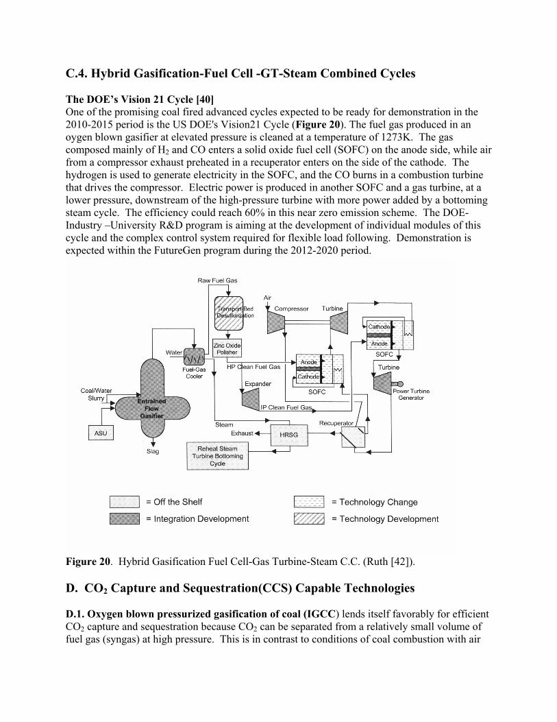
C.4. Hybrid Gasification-Fuel Cell -GT-Steam Combined Cycles The DOE’s Vision 21 Cycle [40] One of the promising coal fired advanced cycles expected to be ready for demonstration in the 2010-2015 period is the US DOE's Vision21 Cycle (Figure 20). The fuel gas produced in an oygen blown gasifier at elevated pressure is cleaned at a temperature of 1273K. The gas composed mainly of H2 and CO enters a solid oxide fuel cell (SOFC) on the anode side, while air from a compressor exhaust preheated in a recuperator enters on the side of the cathode. The hydrogen is used to generate electricity in the SOFC, and the CO burns in a combustion turbine that drives the compressor. Electric power is produced in another SOFC and a gas turbine, at a lower pressure, downstream of the high-pressure turbine with more power added by a bottoming steam cycle. The efficiency could reach 60% in this near zero emission scheme. The DOE-Industry –University R&D program is aiming at the development of individual modules of this cycle and the complex control system required for flexible load following. Demonstration is expected within the FutureGen program during the 2012-2020 period.
Figure 20. Hybrid Gasification Fuel Cell-Gas Turbine-Steam C.C. (Ruth [42]). D. CO2 Capture and Sequestration(CCS) Capable Technologies D.1. Oxygen blown pressurized gasification of coal (IGCC) lends itself favorably for efficient CO2 capture and sequestration because CO2 can be separated from a relatively small volume of fuel gas (syngas) at high pressure. This is in contrast to conditions of coal combustion with air
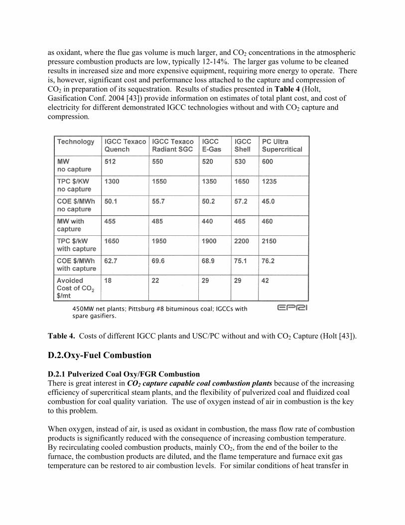
as oxidant, where the flue gas volume is much larger, and CO2 concentrations in the atmospheric pressure combustion products are low, typically 12-14%. The larger gas volume to be cleaned results in increased size and more expensive equipment, requiring more energy to operate. There is, however, significant cost and performance loss attached to the capture and compression of CO2 in preparation of its sequestration. Results of studies presented in Table 4 (Holt, Gasification Conf. 2004 [43]) provide information on estimates of total plant cost, and cost of electricity for different demonstrated IGCC technologies without and with CO2 capture and compression.
Table 4. Costs of different IGCC plants and USC/PC without and with CO2 Capture (Holt [43]). D.2.Oxy-Fuel Combustion D.2.1 Pulverized Coal Oxy/FGR Combustion There is great interest in CO2 capture capable coal combustion plants because of the increasing efficiency of supercritical steam plants, and the flexibility of pulverized coal and fluidized coal combustion for coal quality variation. The use of oxygen instead of air in combustion is the key to this problem. When oxygen, instead of air, is used as oxidant in combustion, the mass flow rate of combustion products is significantly reduced with the consequence of increasing combustion temperature. By recirculating cooled combustion products, mainly CO2, from the end of the boiler to the furnace, the combustion products are diluted, and the flame temperature and furnace exit gas temperature can be restored to air combustion levels. For similar conditions of heat transfer in
450MW net plants; Pittsburg #8 bituminous coal; IGCCs with spare gasifiers.
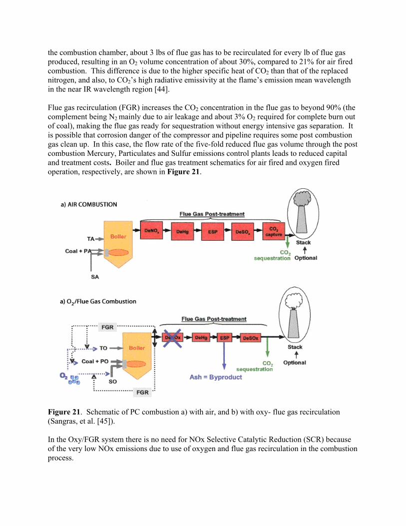
the combustion chamber, about 3 lbs of flue gas has to be recirculated for every lb of flue gas produced, resulting in an O2 volume concentration of about 30%, compared to 21% for air fired combustion. This difference is due to the higher specific heat of CO2 than that of the replaced nitrogen, and also, to CO2’s high radiative emissivity at the flame’s emission mean wavelength in the near IR wavelength region [44]. Flue gas recirculation (FGR) increases the CO2 concentration in the flue gas to beyond 90% (the complement being N2 mainly due to air leakage and about 3% O2 required for complete burn out of coal), making the flue gas ready for sequestration without energy intensive gas separation. It is possible that corrosion danger of the compressor and pipeline requires some post combustion gas clean up. In this case, the flow rate of the five-fold reduced flue gas volume through the post combustion Mercury, Particulates and Sulfur emissions control plants leads to reduced capital and treatment costs. Boiler and flue gas treatment schematics for air fired and oxygen fired operation, respectively, are shown in Figure 21.
Figure 21. Schematic of PC combustion a) with air, and b) with oxy- flue gas recirculation (Sangras, et al. [45]). In the Oxy/FGR system there is no need for NOx Selective Catalytic Reduction (SCR) because of the very low NOx emissions due to use of oxygen and flue gas recirculation in the combustion process.
Reduction of NOx emission from Oxy/FGR combustion. The effective NOx reduction with Oxy/FGR deserves special mention. The bulk of NOx formed in coal combustion is due to the oxidation of fuel-nitrogen. As the coal is injected into the flame it is dried and pyrolyzed, with a fraction of the organically bound “fuel N” evolving with the coal volatiles, and the rest remaining in the char. In the fuel-rich first stage of a two stage (rich-lean) combustion system, the fuel N evolved with the volatiles can be readily converted to molecular nitrogen. Nitrogen evolves from the char as the char burns, and a fraction of the char nitrogen that is carried over to the fuel-lean stage of combustion is oxidized to NOx. [46, 52]. In Oxy /FGR combustion, due to the higher temperature of the early flame, a larger fraction of the coal mass evolves as volatile matter [48] which creates favorable conditions for the reduction of the fuel N to N2. Another factor leading to strongly reduced NOx emission is “NOx reburn”, i.e., reaction of NOx in the recirculated flue gas with hydrocarbon fragments in the volatile flame [47]. This reaction converts the recirculated NOx to molecular nitrogen, N2, in the fuel–rich part of the flame. Results of pilot plant studies indicate that the NOx emission from Oxy-FGR combustion is sufficiently low to satisfy the tightest emission standards without SCR. There is, however, a caveat: as the rate of recirculation increases, the NOx emission also increases [45]. This is because the lower flame temperature near the burner decreases the volatile yield and reduces also the conversion of fuel N to N2 [46]. Overall plant performance; Retrofit and New Plant Croiset, et al [49], and Buhre, et al [50] provide comprehensive reviews of studies on Oxy/Coal Combustion. In most of these studies, 90% or more of the CO2 is captured producing a 98% pure CO2 stream. For retrofitting an existing subcritical steam PC plant, the data show the importance of the base plant efficiency. The Air Separation Unit takes about 20%, and the CO2 purification, compression-liquefaction 12 to14% of the gross electricity output of the plant, representing about 1/3 of the plant’s output. The net plant efficiency with CO2 capture is between 23 and 26% (LHV) [53]. For retrofitting a higher efficiency Supercritical PC plant, the energy penalty of CO2 capture is much lower: the total energy output of the plant is reduced by about 20% and conditions are even more favorable for new Supercritical PC plant with a net efficiency of about 34% (LHV) [54]. Among the issues to be resolved is the treatment of the recycle stream; should the SO2 be removed before recycle and should the recycle stream be dried? Unknown are also the purity requirements of the CO2 stream for sequestration. They are less demanding than those in IGCC for entry to the GT, and if the SOx and NOx could be sequestered along with CO2 in the geologic formation, the total dry flue gas of the PC/Oxy plant could be prepared for compression, pipeline transportation and sequestration. Another question concerns the heat balance between steam generation in the furnace by radiation, and superheating the steam mainly in the convection section of the boiler. As the mass flow rate of recirculated flue gas decreases, the furnace temperature rises and more steam is generated by radiation in the furnace section. Under the same conditions the heat transfer in the convective section decreases because of the reduced gas mass flow rate, causing the superheat temperature to drop. In new designs there is a possibility to place a larger part of the superheater into the furnace but for retrofit of existing plant the balancing would need to be done both by the
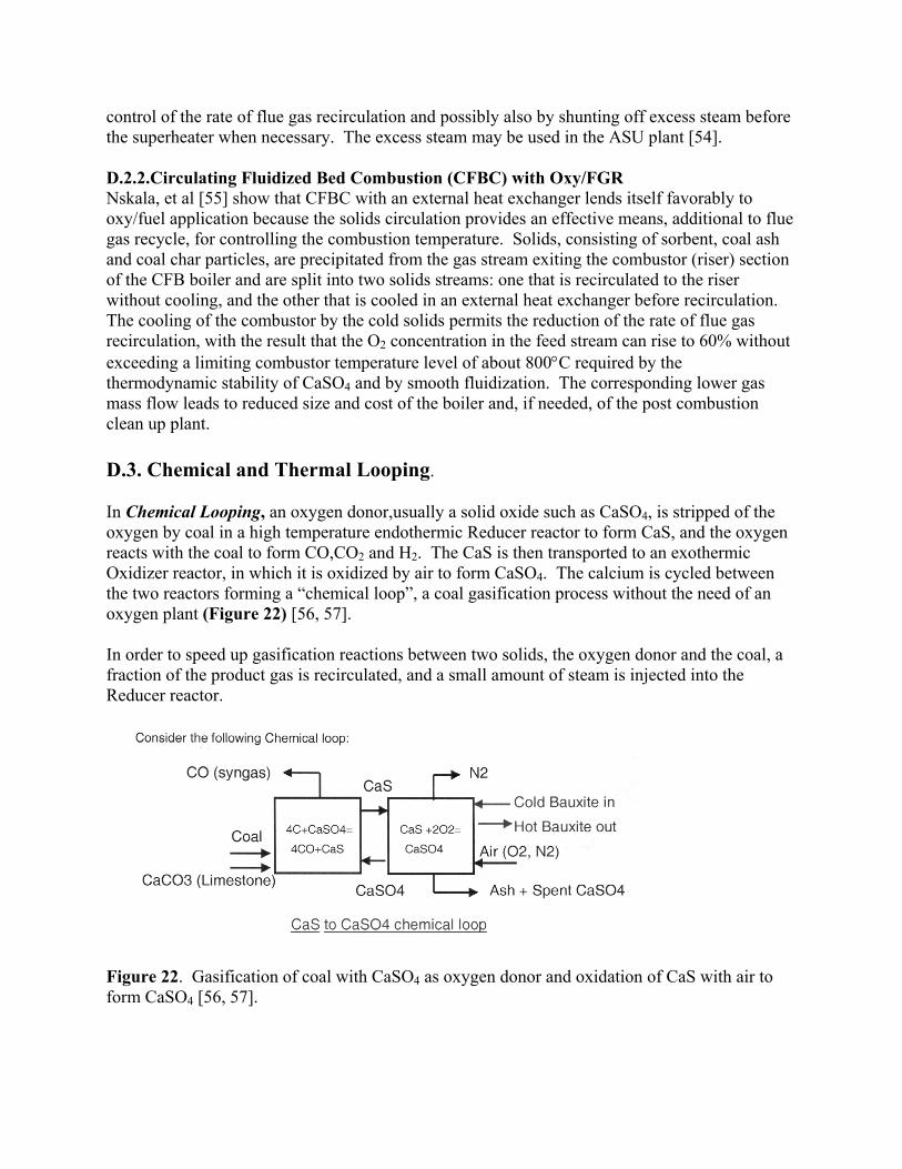
control of the rate of flue gas recirculation and possibly also by shunting off excess steam before the superheater when necessary. The excess steam may be used in the ASU plant [54]. D.2.2.Circulating Fluidized Bed Combustion (CFBC) with Oxy/FGR Nskala, et al [55] show that CFBC with an external heat exchanger lends itself favorably to oxy/fuel application because the solids circulation provides an effective means, additional to flue gas recycle, for controlling the combustion temperature. Solids, consisting of sorbent, coal ash and coal char particles, are precipitated from the gas stream exiting the combustor (riser) section of the CFB boiler and are split into two solids streams: one that is recirculated to the riser without cooling, and the other that is cooled in an external heat exchanger before recirculation. The cooling of the combustor by the cold solids permits the reduction of the rate of flue gas recirculation, with the result that the O2 concentration in the feed stream can rise to 60% without exceeding a limiting combustor temperature level of about 800°C required by the thermodynamic stability of CaSO4 and by smooth fluidization. The corresponding lower gas mass flow leads to reduced size and cost of the boiler and, if needed, of the post combustion clean up plant. D.3. Chemical and Thermal Looping. In Chemical Looping, an oxygen donor,usually a solid oxide such as CaSO4, is stripped of the oxygen by coal in a high temperature endothermic Reducer reactor to form CaS, and the oxygen reacts with the coal to form CO,CO2 and H2. The CaS is then transported to an exothermic Oxidizer reactor, in which it is oxidized by air to form CaSO4. The calcium is cycled between the two reactors forming a “chemical loop”, a coal gasification process without the need of an oxygen plant (Figure 22) [56, 57]. In order to speed up gasification reactions between two solids, the oxygen donor and the coal, a fraction of the product gas is recirculated, and a small amount of steam is injected into the Reducer reactor.
Figure 22. Gasification of coal with CaSO4 as oxygen donor and oxidation of CaS with air to form CaSO4 [56, 57].
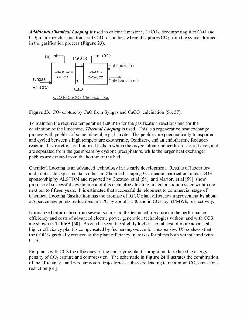
Additional Chemical Looping is used to calcine limestone, CaCO3, decomposing it to CaO and CO2 in one reactor, and transport CaO to another, where it captures CO2 from the syngas formed in the gasification process (Figure 23).
Figure 23. CO2 capture by CaO from Syngas and CaCO3 calcination [56, 57]. To maintain the required temperature (2000ºF) for the gasification reactions and for the calcination of the limestone, Thermal Looping is used. This is a regenerative heat exchange process with pebbles of some mineral, e.g., bauxite. The pebbles are pneumatically transported and cycled between a high temperature exothermic, Oxidizer-, and an endothermic Reducer-reactor. The reactors are fluidized beds in which the oxygen donor minerals are carried over, and are separated from the gas stream by cyclone precipitators, while the larger heat exchanger pebbles are drained from the bottom of the bed. Chemical Looping is an advanced technology in its early development. Results of laboratory and pilot scale experimental studies on Chemical Looping Gasification carried out under DOE sponsorship by ALSTOM and reported by Bozzuto, et al [58], and Marion, et al [59], show promise of successful development of this technology leading to demonstration stage within the next ten to fifteen years. It is estimated that successful development to commercial stage of Chemical Looping Gasification has the promise of IGCC plant efficiency improvement by about 2.5 percentage points, reductions in TPC by about $130, and in COE by $3/MWh, respectively. Normalized information from several sources in the technical literature on the performance, efficiency and costs of advanced electric power generation technologies without and with CCS are shown in Table 5 [60]. As can be seen, the slightly higher capital cost of more advanced, higher efficiency plant is compensated by fuel savings–even for inexpensive US coals–so that the COE is gradually reduced as the plant efficiency increases for plants both without and with CCS. For plants with CCS the efficiency of the underlying plant is important to reduce the energy penalty of CO2 capture and compression. The schematic in Figure 24 illustrates the combination of the efficiency-, and zero emission- trajectories as they are leading to maximum CO2 emissions reduction [61].
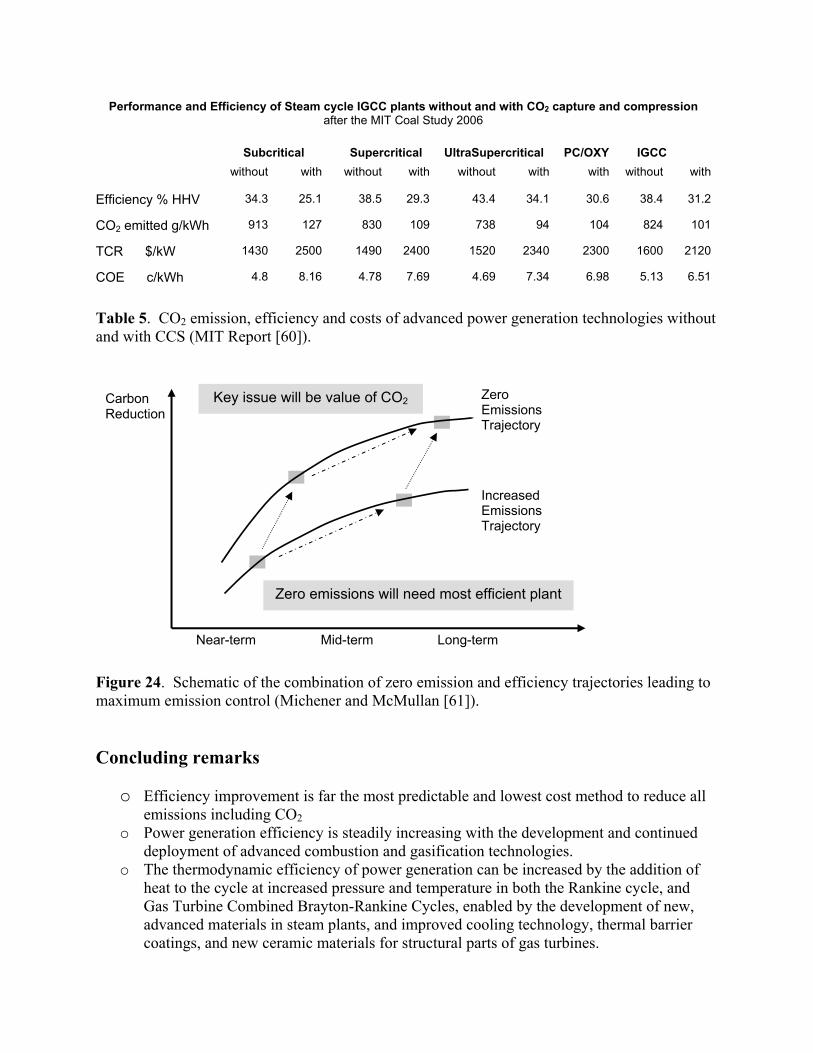
Performance and Efficiency of Steam cycle IGCC plants without and with CO2 capture and compression after the MIT Coal Study 2006
Subcritical Supercritical UltraSupercritical PC/OXY IGCC without with without with without with with without with
Efficiency % HHV 34.3 25.1 38.5 29.3 43.4 34.1 30.6 38.4 31.2
CO2 emitted g/kWh 913 127 830 109 738 94 104 824 101
TCR $/kW 1430 2500 1490 2400 1520 2340 2300 1600 2120
COE c/kWh 4.8 8.16 4.78 7.69 4.69 7.34 6.98 5.13 6.51
Table 5. CO2 emission, efficiency and costs of advanced power generation technologies without and with CCS (MIT Report [60]).
Figure 24. Schematic of the combination of zero emission and efficiency trajectories leading to maximum emission control (Michener and McMullan [61]). Concluding remarks
o Efficiency improvement is far the most predictable and lowest cost method to reduce all emissions including CO2
o Power generation efficiency is steadily increasing with the development and continued deployment of advanced combustion and gasification technologies.
o The thermodynamic efficiency of power generation can be increased by the addition of heat to the cycle at increased pressure and temperature in both the Rankine cycle, and Gas Turbine Combined Brayton-Rankine Cycles, enabled by the development of new, advanced materials in steam plants, and improved cooling technology, thermal barrier coatings, and new ceramic materials for structural parts of gas turbines.
Key issue will be value of CO2
Zero emissions will need most efficient plant
Zero Emissions Trajectory
Increased Emissions Trajectory
Carbon Reduction
Near-term Mid-term Long-term
o Natural Gas Combined Cycle plants are the highest efficiency, cleanest and lowest capital cost power plants, but the high and volatile price of natural gas makes them unattractive for base load operation.
o There is great interest in the continued development and application of Clean Coal Technologies because of the secure and economic coal supply, and the capability of coal utilization technologies to comply with increasingly tight environmental controls.
o In addition to combustion process modifications and post combustion cleanup, the improving efficiency of combustion and gasification cycles are leading to significant reductions in pollutant and CO2 emissions.
o Presently available PC, CFB and IGCC plants have efficiencies of about 8 percentage points, or a relative 25% higher than the installed plant average, with correspondingly higher environmental performance.
o Reductions in emissions as a result of increased efficiency would become clearer if emissions were related to the output (per kWh or MWh) of the plant. The present system of input based emission standards (lb/MBtu or g/Nm3) hide the environmental advantage of efficiency and is not therefore conducive to the choice of advanced, high efficiency power plants.
o The “zero emission” coal plant of the future will include CO2 capture and compression for sequestration (CCS), a technology expected to come to fruition in the mid 2020s.
o Prior to the commercial application of CCS, the most cost effective way of reducing all emissions including CO2 from new coal based power plants is to deploy plants with the highest efficiency commensurate with cost and availability.
o In the near term, the choice of coal based generating technology without CCS is PC or CFBC in Supercritical, or for PC also Ultra Supercritical steam cycle. While IGCC has a smaller cost differential between no-capture and capture plant, IGCC without CO2 capture it is not presently competitive on cost and on availability with PC or CFBC plants.
o IGCC with CCS technology is likely to emerge as the eventual sustainable coal fuelled option; it has the advantage of providing the base for the future Hybrid Fuel Cell/GT/Steam coal plant with 60% cycle efficiency and near zero emission.
o The primary coal based electricity generating technologies with CO2 capture (CCS) are IGCC with pre-combustion capture, PC with post-combustion capture, and oxy-fired PC or CFBC Flue gas clean up for Oxy combustion plant has to satisfy standards for compression, pipeline transportation and sequestration that are less stringent than those for gas turbine entry in IGCC. The sequestration of the dry flue gas without CO2 separation could make Oxy combustion in SC and USC steam plants competitive with IGCC.
o Additional to increased plant cost, CO2 capture involves significant performance and efficiency reduction, and it is essential therefore that the underlying plant efficiency be as high as possible.
o Cost comparisons of advanced coal based power generating systems show that not withstanding the marginally higher first cost of higher efficiency plants, the COE and the output based emissions are reduced as the efficiency increases in plants both without and with CO2 capture.
Acknowledgements The author is grateful for valuable information received from Nancy Mohn , John Marion and Carl Bozzuto (Alstom), Nevill Holt and Stu Dalton(EPRI), Adel Sarofim(Univ. of Utah), Jim Katzer ,Gregory McRae, Howard Herzog, and Mark Bohm (MIT), in the course of writing this paper. Thanks are due to Don McGaffigan for his helpful assistance in the production of the manuscript and the illustrations in the paper. References: 1. Termuehlen,H. and W.Empsperger: Clean and Efficient Coal Fired Power plants. ASME
Press,New York, 2003. 2. Schilling,H.D.:VGB Kraftwerkstechnik 1993;73(8)pp.564-76 (English Edition) 3. Büki G.,Magyar Energiatechnika 1998;6:33-42. 4. Steam its generation and use, Babcock and Wilcox, Schultz, S.C. and J.B. Kitto eds., 1992.
p. 24-10. 5. Henry, J.F., J.D.Fishburn, I.J.Perrin, B.Scarlin, G.N. Stamatelopoulos, R. Vanstone ,29th
Int. Conf. on Coal Utilization & Fuel Systems 2004, pp.1028-42, US DOE, ASME. 6. Armor, A.F., R Viswanathan, S.M. Dalton, 28th Int. Conf. on Coal Utilization & Fuel
Systems, 2003, pp.1426-38 US DOE, ASME. 7. John Marion, ALSTOM Power, Private communication 2005. 8. Blum R. and J. Hald, ELSAM Skaerbaek Denmark, 2002. 9. Kjaer, S., F. Klauke, R. Vanstone, A. Zeijseink, G. Weissinger, P. Kristensen, J. Meier, R.
Blum, K. Wieghardt, Powergen Europe, 2001, Brussels Belgium. 10. Palkes, M., “Boiler Materials for Ultra Supercritical Coal Power PlantsConceptual
Design ALSTOM Approach”, NETL-DOE, 2003, USC T-1. 11. Booras, G. and N. Holt, Pulverized Coal and IGCC plant Cost and Performance Estimates,
Gasification Technologies Conference Washington D.C. 2004. 12. Chiesa, P. and E. Macchi, Tans. ASME, Journal of Engineering for Gas Turbine and
Power, Vol 126; No.4, pp. 770-85, 2004. 13. Meisl, J., K. Kapp, W. Leuckel, S. Wittig, Forschungsberichte Verbrennungs
Kraftmaschienen FVV, 1994. 14. Frutschi, H.U., Gas turbines with sequential combustion for cogeneration of heat and
power. ABB Review 1995/3. 15. Hauenschild, R and B. Imwinkel, Int. Joint Power Generation Conf. VGB/ASME Phoenix,
AZ, 1994. 16. Foster-Pegg, R.W., Westinghouse Electric Co Intersociety Energy Conversion Conference,
San Francisco, Ca. 1984. 17. Mannesmann Edelstahlrohr Gmbh, A High Temperature Corrosion Resistant Material of
Construction AC66(X5 NiCrNb3227) Report of public presentation, Duisberg-Huckingen, Germany, March 1989.
18. Seery, D and J. Sangiovanni, Proc. Adv. Coal Based Power and Environmental Systems 1998 Conf. DOE FETC Morgantown, PA.
19. BBeeéérr,, JJ..MM..,, aanndd VV.. HHoommoollaa,, IInnnnoovvaattiivvee TTeecchhnnoollooggiiccaall IInniittiiaattiivveess ttoo UUppggrraaddee PPoowweerr PPllaannttss,, IIEEAA--UUSSDDOOEE--UUSSAAIIDD IInntteerrnnaattiioonnaall CCoonnffeerreennccee iinn CClleeaann CCooaall UUttiilliizzaattiioonn,, BBuuddaappeesstt,, HHuunnggaarryy,, FFeebbrruuaarryy 2244--2288,, 11999922..
20. Robson, F.L. and D. Seery, ASME paper No 94-JPGC-GT-6, 1994. 21. Bose A., D. Bonk, Z. Fanand, A. Robertson, Proc. 29th Int. Tech. Conf.on Coal Utilization
& Fuel Systems, US DOE,ASME pp624-33. 2004. 22. Robertson, A., R.Garland, R. Newby, A. Rehmat and L. Rebow (1989) Second Generation
Pressurized Fluidized Bed Combustion Plant, Foster Wheeler Dev. Corp. Report to the US DOE DE-AC-21-86MC21023.
23. Beér, J.M. and R.V. Garland: A Coal Fueled Combustion Turbine Cogeneration System with Topping Combustion, Trans. ASME Journ. of Engineering for Gas Turbines and Power Vol. 119, No.1, pp.84-92,1997.
24. Domeracki, W.F., Dowdy, T.E., and Bachovchin, D.M., Topping Combustor Status for Second Generation Pressurized Fluid Bed Cycle Application, ASME Paper 95-GT-106 (1995).
25. Beér, J.M., Dowdy, T.E., and Bachovchin, D.M., US Patent No. 5636510 (1997). 26. Phillips J.N., I&C Needs of IGCC Proc. of the 48th Annual ISA POWID Symposium 2005. 2277.. BBeeéérr JJ..MM..,, CCooaall--WWaatteerr FFuueell CCoommbbuussttiioonn;; FFuunnddaammeennttaallss aanndd AApppplliiccaattiioonn.. AA NNoorrtthh
AAmmeerriiccaann OOvveerrvviieeww,, SSeeccoonndd EEuurrooppeeaann CCoonnff.. oonn CCooaall LLiiqquuiidd MMiixxttuurreess,,II..CChheemm..EE..SSyymmppoossiiuumm SSeerr..NNoo..9955.. LLoonnddoonn,, EEnnggllaanndd,, 11998855..
2288.. BBeeéérr,, JJ..MM..,, aanndd GG.. VVeerrmmeess,, GGaass TTuurrbbiinnee CCoommbbuussttoorr ffoorr CCooaall--WWaatteerr SSlluurrrriieess,, AASSMMEE EEnnggiinneeeerriinngg FFoouunnddaattiioonn CCoonnffeerreennccee oonn TToommoorrrrooww’’ss FFuueellss,, aatt SSaannttaa BBaarrbbaarraa,, CCAA,, NNoovveemmbbeerr 77--1122,, 11998822..
29. Holt N. Gasification Technology Conference, San Francisco Oct. 2004. 30. The Stamet Pump, in Clean Coal Today, Newsletter of the Office of Fossil Energy
USDOE; DOE/FE-0486 Issue #63. 2005. 31. Reid W.T., External Corrosion and Deposits, Boilers and Gas Turbines, Elsevier Fuel and
Energy Science Monograph Series, ed. J.M. Beér 1971. 32. Dolezal, R., Schmelzfeuerungen, Theorie, Bau und Betrieb, VEB Verlag Technik,Berlin
1954. 33. Dolezal, R., Large Boiler Furnaces, Fuel and Energy Monograph Series, ed. J.M. Beér,
Elsevier, New York 1967. 34. Henderson C., Understanding Coal Fired Power Plant Cycles, IEA CCC/91 2004. 35. Lovis M, Drdziok A, Witchow A. In: Proc. Power-Gen Europe 1994; Penn Well, Utrecht
The Netherlands 1994, pp.327-49. 36. Couch G.R. OECD Coal Fired Power Generation IEA Per/33, 1997. 37. Holt N, G. Booras and D. Todd, The Gasification Technologies Conference, San Francisco,
CA 2003. 38. Dennis, R.A., The DOE FE Turbine Program, Presentation to NRC Panel on DOE’s IGCC
R&D Program, Washington DC, Oct.2005. 39. US National Research Council Panel on DOE’s IGCC Program, Washington, DC 2006. 40. Haupt, G. and J. Karg, The Role of IGCC in Advanced Power Generation Power-Gen
Asia’97 Singapore, Sep.1997; Siemens Power Generation 1997. 41. Wright, T.L.,Coal Gasification-Back to the Future? Proc. 26th Int. Tech Conf. on Coal
Utilization and Fuel Systems, USDOE 2003. pp 225-235. 42. Ruth, L.A., US DOE Vision21 Workshop, FETC Pittsburgh, PA, Dec.1998.
43. Holt, N., Gasification Process Selection-Trade-offs and Ironies, Gasification Technologies Conference, Washington DC, 2004.
44. Hottel, H.C., A.F. Sarofim, Radiative Heat Transfer, McGraw-Hill, New York 1967. 45. Sangras, R,F.Chatel-Pelage, P. Pranda, H. Farzan, S. Vecci, Y. Lu, Oxy-combustion
process in pulverized coal boilers; a promising technology for COP2 capture, The 29th International Technical Conference on Coal Utilization and Fuel Systems, Clearwater, FL, April 2004.
46. GGooeell,, SS..KK..,, JJ..MM.. BBeeéérr aanndd AA..FF.. SSaarrooffiimm,, AAnn EEmmiissssiioonnss MMooddeell ffoorr aa BBuubbbblliinngg FFBBCC UUssiinngg DDeettaaiilleedd CChheemmiiccaall KKiinneettiiccss:: SSiiggnniiffiiccaannccee ooff DDeessttrruuccttiioonn RReeaaccttiioonnss,, JJ.. IInnsstt.. EEnneerrggyy,, VVooll LLXXIIXX,, NNoo 448811,, DDeecceemmbbeerr 11999966..
47. Wendt, J.O.L, C.V. Streling, J. Air Pollut. Contr. Ass. 24, 1055 (1974). 48. Howard, J.B., in Chemistry of Coal Utilization, Second Supplimentary Volume (M.A
Elliott, Ed.)Wiley, New York, 1981, pp 665-784. 49. Croiset, E and K.V. Thambimuthu, Coal combustion with flue gas recirculation for CO2
recovery, Greenhouse Gas Control Technologies, P Riemer, B. Eliassonand, A. Wokaun, editors, 1999 Elsevier Science Ltd.
50. Buhre, B.J.P., L.K. Elliott, C.D. Sheng, R.P. Gupta, T.F. Wall, Oxy-fuel combustion technology for coal fired power generation Progress in Energy and Combustion Science, Vol 31 No.4. pp 283-307, 2005.
51. Khare, S., T. Wall, R. Gupta, L. Elliott, B. Buhre, Retrofitting of air-fired pf plant to oxy-fuel: heat transfer impacts for the furnace and convective pass and associated oxygen production requirements 5th Asia-Pacific Conference on Combustion, Adalaide, July 2005.
52. BBeeéérr,, JJ..MM..,, LLooww NNOOxx BBuurrnneerrss ffoorr BBooiilleerrss,, FFuurrnnaacceess aanndd GGaass TTuurrbbiinneess;; DDrriivvee TToowwaarrddss tthhee LLoowweerr BBoouunnddss ooff NNOOxx EEmmiissssiioonnss,, IInnvviitteedd LLeecctt..,, TThhiirrdd IInntteerrnnaattiioonnaall CCoonnffeerreennccee oonn CCoommbbuussttiioonn TTeecchhnnoollooggiieess ffoorr aa CClleeaann EEnnvviirroonnmmeenntt,, LLiissbboonn,, PPoorrttuuggaall,, 11999955;; CCoommbbuusstt.. SSccii.. aanndd TTeecchh.. VV.. 112211,, 11--66,, pp..116699,, 11999966..
53. Anderson K., Birkstead H., Maksinen P., Johnsson F., Stroemberg L., and Lyngfelt l., An 865MW Lignite fired CO2 free power plant-Technical feasibility study, Proc. of the 6th Conference on Greenhouse Gas Control Technologies,(CHGT-6) Kyoto, Japan 2002.
54. Dillon D.J., Panesar R.S., Wall R.A., Allam R.J., White V., Gibbins J., and Haines M.R., Oxy-Combustion processes for CO2 capture from advanced supercritical PF and NGCC plant Proc. of the Seventh Conference on Greenhouse Gas Control Technologies (CHGT-7), Vancouver, BC, Canada, 2004.
55. Nsakala, Liljedahl et al., Greenhouse Gas Emissions Control in Circulating Fluidized Bed Boilers US DOE/NETL [48] Cooperative Agreement May 2003.
56. Moss G., The Oxygen Donor Gsification Process in: Howard J.R., Fluidized Beds Combustion and Applications, Applied Science Publishers, London and New York 1983.
57. Turek D.G., G. N. Liljedahl, Nsakala ya Nsakala, H.E. Andrus, John H. Chiu, ALSTOM’s development of advanced CFB based technologies for CO2 mitigation, Proc. 30th International Technical Conference on Coal Utilization and Fuel Systems, Clearwater, Florida US DOE 2005.
58. Bozzuto C. and N. Mohn, Environmentally Advanced Clean Coal Plants, 19th World Energy Congress, Sydney, Autralia, Sep.6-9 2004.
59. Marion J., C. Bozzuto, N. Nsakala, G. Lijedahl, Evaluation of advanced coal combustion & gasification power plants with greenhouse gas emission control, Topical Phase 1. DOE-NETL Report No. DE-FC26-01NT41146, Prepared by ALSTOM 2003.

60. Deutch J. and E. Moniz, The future of coal in a greenhouse constrained world MIT Report in preparation 2006.
61. Minchener A. and J. McMullan, A strategy for sustainable power generation from fossil fuels in Europe Energy World, May 2005. pp. 18-21.