Embed Size (px)
Citation preview

1
Beef Cattle Anatomy and Ultrasound
Collecting quality ultrasound images and accurately interpreting these images
requires an understanding of beef cattle anatomy. There are important shifts and shape
changes that take place during the transformation from a standing beef animal to a
hanging beef carcass.
Figure 1A and 1B relate the changes that take place in skeletal orientation from a
standing beef animal to a hanging beef carcass, where the hind leg is essentially rotated
90°. This change in hind leg position results in shape changes in certain muscles as the
carcass is chilled. Also during the harvesting process a combination of warm, soft fat and
hide pullers may result in fat shifts or fat removed before the chilling process.
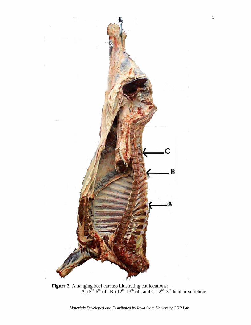
Figure 2 illustrates the rib and lumbar section that was removed, to be used in a
standing frozen state. The 5th-6th rib juncture is where the chuck is separated from the rib.
The 12th-13th rib juncture separates the front quarter from the hindquarter, resulting in a
seven rib section. The remaining 13th rib and two lumbar vertebrae represent the final
section removed.
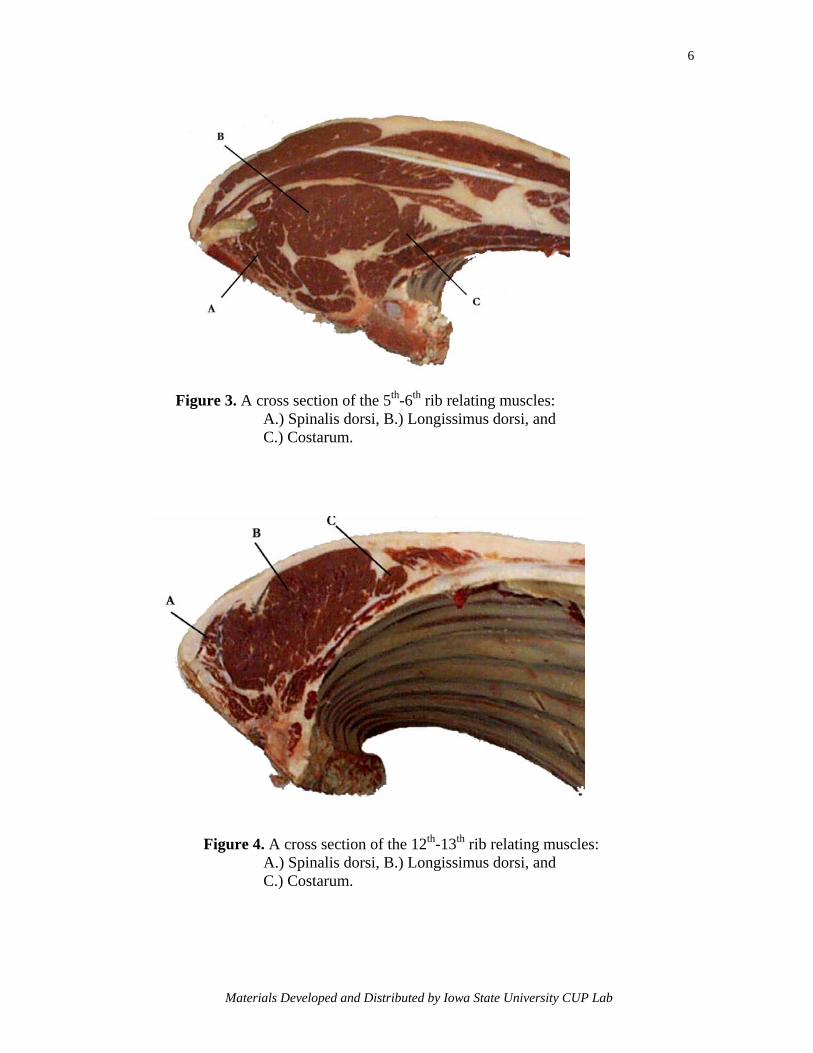
A cross-section between the chuck and rib (5th-6th rib juncture) illustrates the large
number of different muscles in the forequarter (Figure 3). Three muscles used in
ultrasound scanning have been identified in this figure. Note the size and shape of the
spinalis dorsi and the costarum muscle. These muscles become smaller when moving
posterior through the rib section. The longissimus dorsi, however, becomes larger and
elongated moving in a posterior direction towards the 12th-13th rib juncture, as shown in
Figure 4, the location where a cross-sectional ultrasound image is taken.
Materials Developed and Distributed by Iowa State University CUP Lab
2
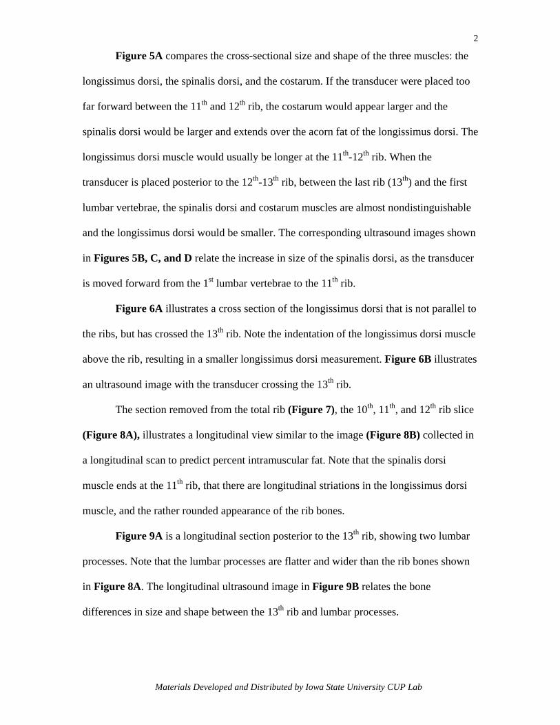
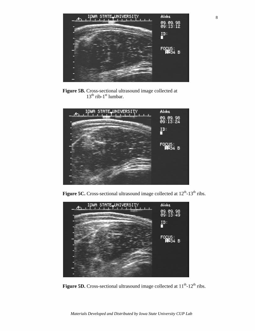
Figure 5A compares the cross-sectional size and shape of the three muscles: the
longissimus dorsi, the spinalis dorsi, and the costarum. If the transducer were placed too
far forward between the 11th and 12th rib, the costarum would appear larger and the
spinalis dorsi would be larger and extends over the acorn fat of the longissimus dorsi. The
longissimus dorsi muscle would usually be longer at the 11th-12th rib. When the
transducer is placed posterior to the 12th-13th rib, between the last rib (13th) and the first
lumbar vertebrae, the spinalis dorsi and costarum muscles are almost nondistinguishable
and the longissimus dorsi would be smaller. The corresponding ultrasound images shown
in Figures 5B, C, and D relate the increase in size of the spinalis dorsi, as the transducer
is moved forward from the 1st lumbar vertebrae to the 11th rib.
Figure 6A illustrates a cross section of the longissimus dorsi that is not parallel to
the ribs, but has crossed the 13th rib. Note the indentation of the longissimus dorsi muscle
above the rib, resulting in a smaller longissimus dorsi measurement. Figure 6B illustrates
an ultrasound image with the transducer crossing the 13th rib.
The section removed from the total rib (Figure 7), the 10th, 11th, and 12th rib slice
(Figure 8A), illustrates a longitudinal view similar to the image (Figure 8B) collected in
a longitudinal scan to predict percent intramuscular fat. Note that the spinalis dorsi
muscle ends at the 11th rib, that there are longitudinal striations in the longissimus dorsi
muscle, and the rather rounded appearance of the rib bones.
Figure 9A is a longitudinal section posterior to the 13th rib, showing two lumbar
processes. Note that the lumbar processes are flatter and wider than the rib bones shown
in Figure 8A. The longitudinal ultrasound image in Figure 9B relates the bone
differences in size and shape between the 13th rib and lumbar processes.
Materials Developed and Distributed by Iowa State University CUP Lab

3
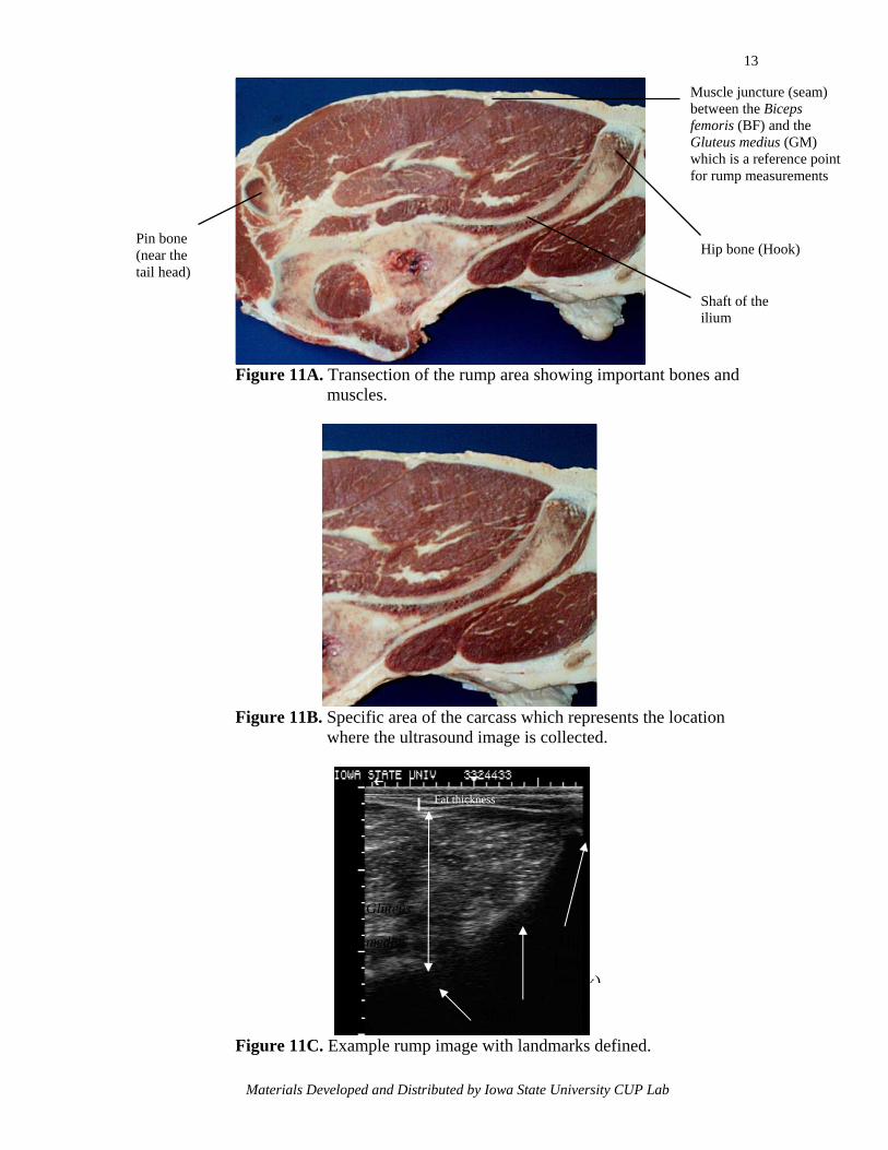
Figures 10A and 10B suggest where the rump and round would be fabricated to
produce a transection, which is shown in Figure 11A. Figure 11B shows the specific
area of the carcass where the ultrasound image (Figure 11C) is collected. Note the
Gluteus medius depth measurement is taken between the Biceps femoris-Gluteus medius
juncture and the shaft of the ilium.
Figure 1A. Skeleton superimposed on a beef steer.
Materials Developed and Distributed by Iowa State University CUP Lab

4
Figure 1B. Skeleton superimposed on a beef carcass.
Materials Developed and Distributed by Iowa State University CUP Lab
5
Figure 2. A hanging beef carcass illustrating cut locations: A.) 5th-6th rib, B.) 12th-13th rib, and C.) 2nd-3rd lumbar vertebrae.
Materials Developed and Distributed by Iowa State University CUP Lab
6
Figure 3. A cross section of the 5th-6th rib relating muscles:
A.) Spinalis dorsi, B.) Longissimus dorsi, and C.) Costarum.
Figure 4. A cross section of the 12th-13th rib relating muscles:
A.) Spinalis dorsi, B.) Longissimus dorsi, and C.) Costarum.
Materials Developed and Distributed by Iowa State University CUP Lab

7
Figure 5A. Three cross-sectional rib cuts between the:
I.) 13th-1st lumbar, II.) 12th-13th ribs, and III.) 11th-12th ribs.
Materials Developed and Distributed by Iowa State University CUP Lab
8
Figure 5B. Cross-sectional ultrasound image collected at 13th rib-1st lumbar.
Figure 5C. Cross-sectional ultrasound image collected at 12th-13th ribs.
Figure 5D. Cross-sectional ultrasound image collected at 11th-12th ribs.
Materials Developed and Distributed by Iowa State University CUP Lab

9
Figure 6A. A cross-sectional cut of the longissimus dorsi muscle with the cut crossing the 13th rib.
Figure 6B. Cross-sectional ultrasound image collected crossing the 13th rib.
Materials Developed and Distributed by Iowa State University CUP Lab

10
Figure 7. A rib section with a longitudinal section from the 10th,11th and 12th ribs removed.
Figure 8A. A longitudinal section relating the 10th,11th
and 12th ribs.
Figure 8B. Longitudinal ultrasound image relating the size of the spinalis Dorsi muscle at the 10th, 11th, and 12th ribs.
Materials Developed and Distributed by Iowa State University CUP Lab

11
2nd lumbar
Psoas
major
1st lumbar Figure 9A. A longitudinal section relating the 1st and 2nd lumbar vertebrae. Note that the lumbar processes are flatter and wider than the rib bones shown in Figure Figure 8A.
Figure 9B. Longitudinal ultrasound image relating bone differences in size and shape when comparing lumbar and thoracic vertebrae.
Materials Developed and Distributed by Iowa State University CUP Lab

12
Figure 10A. Locating the bone to make a transectional cut.
Figure 10B. Making the initial transectional cut.
Materials Developed and Distributed by Iowa State University CUP Lab
13
Muscle juncture (seam) between the Biceps femoris (BF) and the Gluteus medius (GM) which is a reference point
Pin bone (near the tail head)
Figure 11A. T m
Figure 11B. S w
Figure 11C. E
Materials Deve
ransection of the rump aruscles.
pecific area of the carcasshere the ultrasound image
xample rump image with
Shafof
Fat thickness
Gluteus
medius
loped and Distributed by Iowa
for rump measurements
Hip bone (Hook)
Shaft of the ilium
ea showing important bones and
which represents the location is collected.
landmarks defined.
Hip bone (hook)
t
State University CUP Lab