Embed Size (px)
DESCRIPTION
Canadian Company - Catalogue / Booklet AV-MH-KA )Metal Air Valves) Combination Air Release & Air and Vacuum Valves
Citation preview
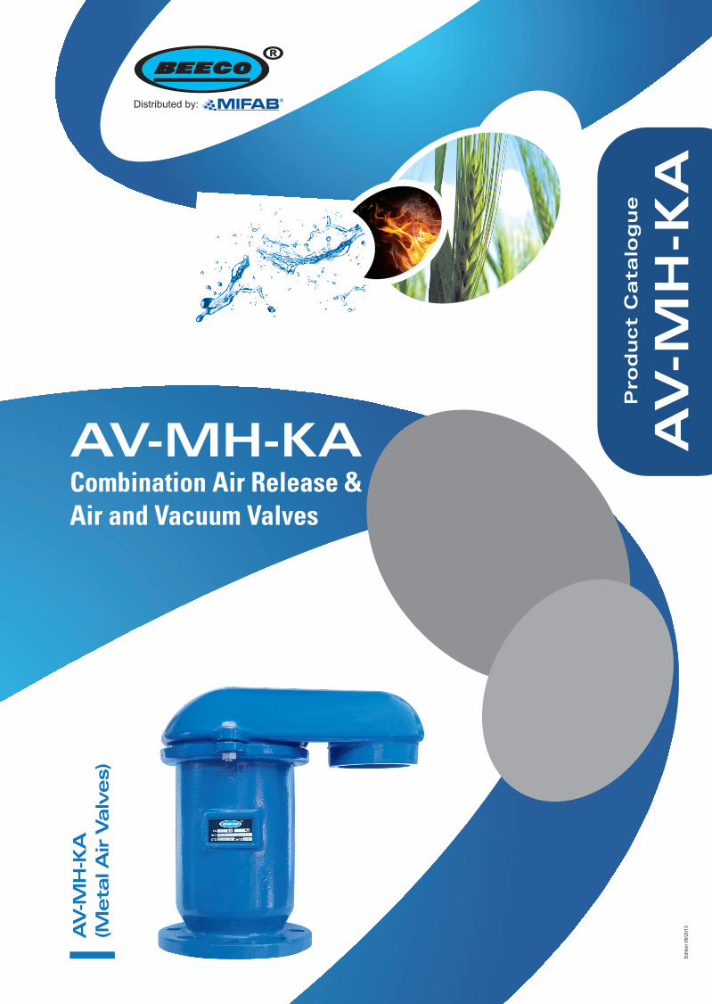
AV-MH-KACombination Air Release & Air and Vacuum Valves
Pro
du
ct
Ca
talo
gu
e
AV
-MH
-KA
AV
-MH
-KA
(Meta
l Air V
alv
es)
Editi
on 0
6/20
13
Distributed by:
AV Series
Edition 06/2013
Distributed by:
2
AV-MH-KA General
AV-MH-KACombination Air Release & Air and Vacuum Valves
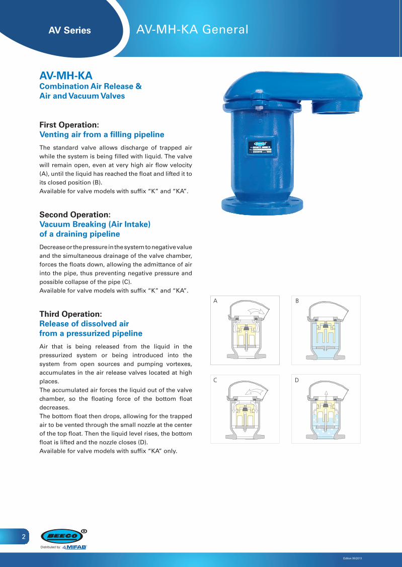
First Operation:Venting air from a filling pipeline
The standard valve allows discharge of trapped air while the system is being filled with liquid. The valve will remain open, even at very high air flow velocity (A), until the liquid has reached the float and lifted it to its closed position (B).Available for valve models with suffix “K” and “KA”.
Second Operation:Vacuum Breaking (Air Intake)of a draining pipeline
Decrease or the pressure in the system to negative value and the simultaneous drainage of the valve chamber, forces the floats down, allowing the admittance of air into the pipe, thus preventing negative pressure and possible collapse of the pipe (C).Available for valve models with suffix “K” and “KA”.
Third Operation:Release of dissolved airfrom a pressurized pipeline
Air that is being released from the liquid in the pressurized system or being introduced into the system from open sources and pumping vortexes, accumulates in the air release valves located at high places. The accumulated air forces the liquid out of the valve chamber, so the floating force of the bottom float decreases. The bottom float then drops, allowing for the trapped air to be vented through the small nozzle at the center of the top float. Then the liquid level rises, the bottom float is lifted and the nozzle closes (D).Available for valve models with suffix “KA” only.
BA
DC
AV Series
Edition 06/2013
Distributed by:
3
AV-MH-KA Technical Data
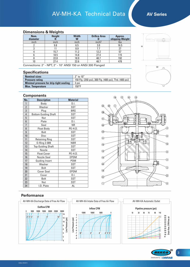
ComponentsNo. Description Material
1 Body D.I.2 Washer SST3 Plug BRS4 Bottom Guiding Shaft SST5 Nut SST6 Plate D.I.7 Seal NR8 Float Body PE-H.D.9 Bolt SST10 Disc SST11 Retaining Ring SST12 O-Ring 2-009 NBR13 Top Guiding Shaft SST14 Nozzle SST15 Float Cover PE-H.D.16 Nozzle Seal EPDM17 Guiding Insert POM18 Washer SST19 Bolt SST20 Cover Seal EPDM21 Cover D.I.22 Bolt SST23 Nut SST24 I.D. Plate AL
Dimensions & WeightsNom.
diameterHeight
HWidth
WOrifice Area
DApprox.
shipping Weightinch inch inch inch2 lbs
2 9.8 6.5 3.0 16.53 11 8.9 7.7 274 15.7 11.2 12.2 576 18.5 14.8 27.4 1158 22.8 18.9 48.7 192
10 27.4 22.6 48.7 478Connections: 2" - NPT, 2" - 10" ANSI 150 or ANSI 300 Flanged
SpecificationsNominal sizes 2” to 10” Pressure rating 150 Flg. (250 psi), 300 Flg. (400 psi), Thd. (400 psi)Minimal pressure for drip-tight sealing 3 psiMax. Temperature 150°F
H
W
1010
111111
1212
1313
1414
1515
1616
1717
181818
1919
2020
2121
66
77
99
33
11
222
44
55
88
2222
2323
2424
222
33
99
±30'±30'A2A2
30-10030-100FINISH:FINISH:
AUTOMATIC CONTROL VALVESAUTOMATIC CONTROL VALVESISSU:ISSU:
FILE NAME:FILE NAME: DRAW. NoDRAW. No
MATERIAL:MATERIAL:
CHE'DCHE'D
SCALE:SCALE:
±0.4±0.4
PART No:PART No:
DAFNADAFNA
±0.8±0.8250-630250-630
SIZE:SIZE: NAMENAME
DRAWNDRAWN
BAHIR IBAHIR I
±0.2±0.2DATEDATE
DESIGNATION:DESIGNATION:
®®630-1600630-1600±0.3±0.3
SIGNSIGN
APP'DAPP'D
0-300-30 100-250100-250±0.5±0.5
GEN. TOLERANCE:GEN. TOLERANCE:
No PART No DESIGNATION MATL DIM. QTY
1 55SH13B00N BODY D.I. 1
2 002170800M WASHER SST M8 2
3 0013825001 PLUG BRS 1/4 NPT 2
4 002V63B000 SHAFT SST 1
5 002100802M NUT SST M8 1
6 55SV23B0M3 PLATE D.I. 1
7 007V33B000 SEAL NR 1
8 445V03B002 FLOAT BODY PE-H.D. 1
9 0028008012 PNH TPG SCREW SST No 8x12 2
10 4421740D40 DISC SST 1
11 0021510471 RETAINING RING SST Ø 10 1
12 0070902009 O-RING 2-009 NBR 1
13 442263B0V0 AXE SST 1
14 442V930000 NOZZLE SST 1
15 44503B001 FLOAT COVER PE-H.D. 1
16 007V820000 NOZZEL SEAL EPDM 1
17 44524340V4 GUIDING INSERT POM 1
18 0021738000 WASHER SST 3/8" (M10) 6
19 0028M10040 BOLT SST M10x40 4
20 007V33B0M2 COVER SEAL EPDM 1
21 55SV23B0M2 COVER D.I. 1
22 0027M10040 BOLT SST M10x40 2
23 002101000M NUT SST M10 2
24 0066534001 I.D. PLATE AL 1
19.7.1219.7.12
JOUKEJOUKE25\ASSY\AIR 3H-16-CATLOG_DE\AIR RELIF\3F-8025\ASSY\AIR 3H-16-CATLOG_DE\AIR RELIF\3F-80
77SHV3BD0N77SHV3BD0N MH-80 AIR RELIEF-16 BARDAV-MH KA
3"
MH-80 AIR RELIEF-16 BARDAV-MH KA
3"
PerformanceAV-MH-KA Discharge Data of Free Air Flow AV-MH-KA Intake Data of Free Air Flow
Inflow CFM
Line P
ressu
re (ps
i)
Outflow CFM
Line P
ressu
re (ps
i)
0-1-2-3-4-5-6-7-8-9
15000 10000 5000 0
10” 8” 6” 4” 3” 2”
14121086420
0 5000 10000 15000 20000 25000 30000
2” 3” 4” 6” 8” 10”
AV-MH-KA Automatic Outlet
10 30 50 70 90 11055050045040035030025020015010050
Pipeline pressure (psi)
Drain
flow,
CFM
free
air10”
8”
6”
4”
2”3”
AV Series
Edition 06/2013
Distributed by:
4
AV-MH-KA-SA General
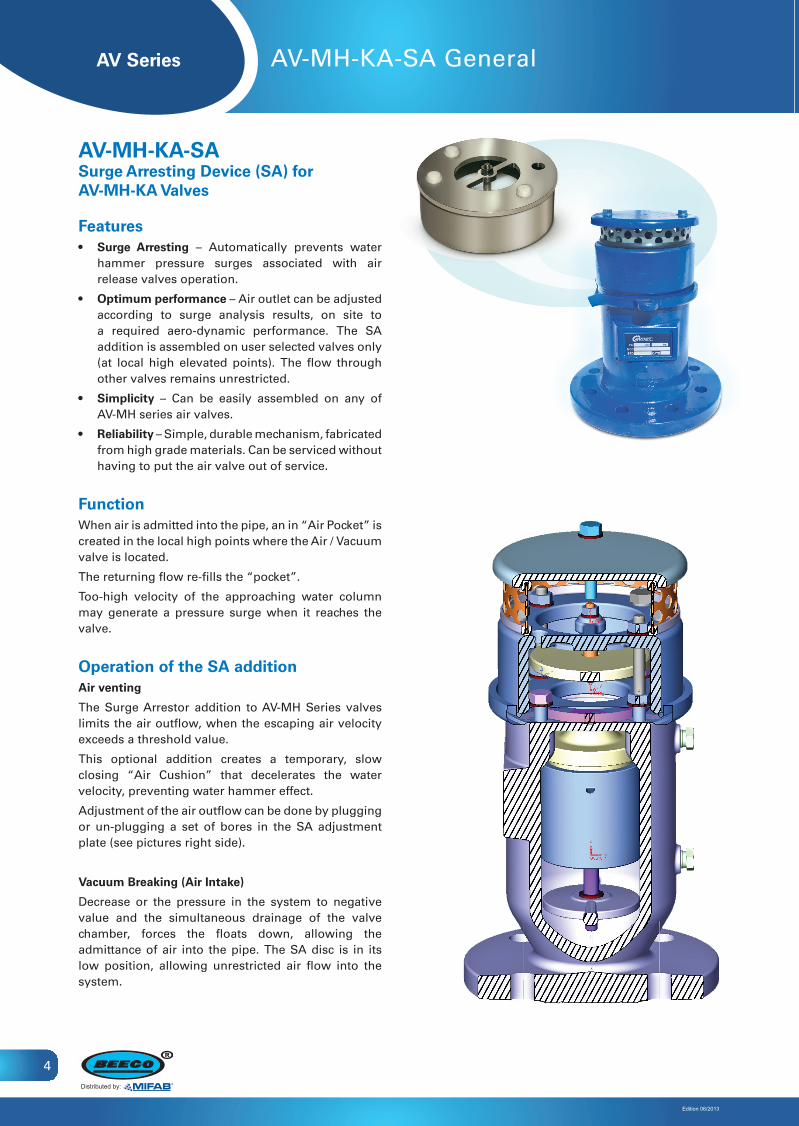
AV-MH-KA-SASurge Arresting Device (SA) for AV-MH-KA Valves
Features• Surge Arresting – Automatically prevents water
hammer pressure surges associated with air release valves operation.
• Optimumperformance – Air outlet can be adjusted according to surge analysis results, on site to a required aero-dynamic performance. The SA addition is assembled on user selected valves only (at local high elevated points). The flow through other valves remains unrestricted.
• Simplicity – Can be easily assembled on any of AV-MH series air valves.
• Reliability – Simple, durable mechanism, fabricated from high grade materials. Can be serviced without having to put the air valve out of service.
FunctionWhen air is admitted into the pipe, an in “Air Pocket” is created in the local high points where the Air / Vacuum valve is located.
The returning flow re-fills the “pocket”.
Too-high velocity of the approaching water column may generate a pressure surge when it reaches the valve.
Operation of the SA additionAir venting
The Surge Arrestor addition to AV-MH Series valves limits the air outflow, when the escaping air velocity exceeds a threshold value.
This optional addition creates a temporary, slow closing “Air Cushion” that decelerates the water velocity, preventing water hammer effect.
Adjustment of the air outflow can be done by plugging or un-plugging a set of bores in the SA adjustment plate (see pictures right side).
Vacuum Breaking (Air Intake)
Decrease or the pressure in the system to negative value and the simultaneous drainage of the valve chamber, forces the floats down, allowing the admittance of air into the pipe. The SA disc is in its low position, allowing unrestricted air flow into the system.
AV Series
Edition 06/2013
Distributed by:
5
AV-MH-KA-SA Technical Data
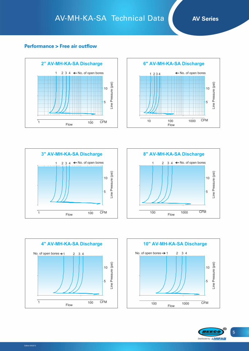
Performance > Free air outflow
100 CFM1
1 2 3 4 No. of open bores
2” AV-MH-KA-SA Discharge
5
10
Line
Pre
ssur
e (p
si)
Flow
5
10
100 CFM
5
10
1
1 2 3 4 No. of open bores
Line
Pre
ssur
e (p
si)
Flow
3" AV-MH-KA-SA Discharge
5
10
100 CFM
5
10
1
No. of open bores
Line
Pre
ssur
e (p
si)
Flow
1 2 3 4
4" AV-MH-KA-SA Discharge
No. of open bores
6" AV-MH-KA-SA Discharge
5
10
Line
Pre
ssur
e (p
si)
Flow
5
10
5
10
No. of open bores
Line
Pre
ssur
e (p
si)
Flow
8" AV-MH-KA-SA Discharge
5
10
5
10
Line
Pre
ssur
e (p
si)
Flow
10" AV-MH-KA-SA Discharge
1000 CFM100
1 2 3 4
CFM100010 100
1 2 3 4
1000 CFM100
1 2 3 4No. of open bores
AV Series
Edition 06/2013
Distributed by:
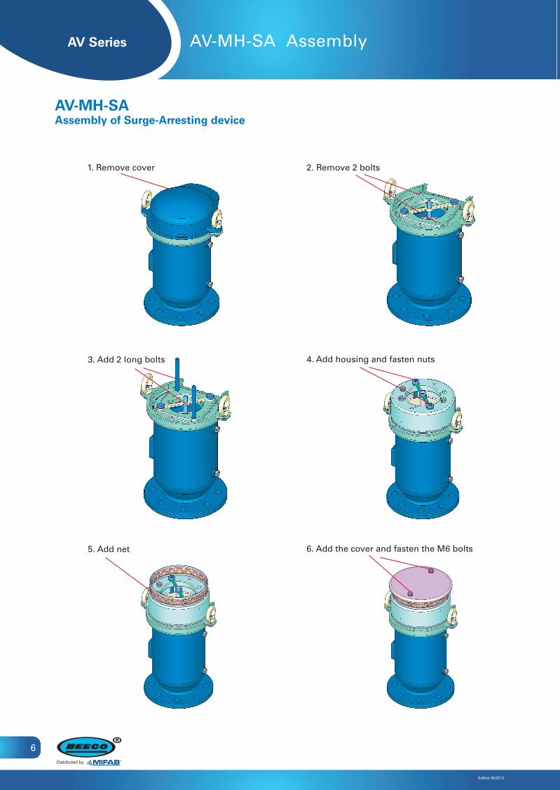
1. Remove cover 2. Remove 2 bolts
3. Add 2 long bolts 4. Add housing and fasten nuts
5. Add net 6. Add the cover and fasten the M6 bolts
6
AV-MH-SA Assembly
AV-MH-SAAssemblyofSurge-Arrestingdevice
AV Series
Edition 06/2013
Distributed by:
7
Ordering Guide
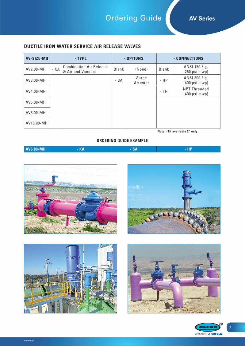
AV-SIZE-MH - TYPE - OPTIONS - CONNECTIONS
AV2.00-MH - KA Combination Air Release & Air and Vacuum Blank (None) Blank ANSI 150 Flg.
(250 psi mwp)
AV3.00-MH - SA Surge Arrestor - HP ANSI 300 Flg.
(400 psi mwp)
AV4.00-MH - TH NPT Threaded(400 psi mwp)
AV6.00-MH
AV8.00-MH
AV10.00-MH
AV6.00-MH - KA - SA - HP
DUCTILE IRON WATER SERVICE AIR RELEASE VALVES
Note: -TH available 2” only
ORDERING GUIDE EXAMPLE

Innovation Innovation
Expertise Expertise
ReliabilityReliability
Distributed by:
BEECO, Inc. 1321 West 119th Street, Chicago Illinois 60643-5109, USA
Toll Free: 1-800-465-2736, Fax: 1-773-341-3049Canada Toll Free: 1-800-387-3880
www.beecoacv.com [email protected]
Hundreds of companies in the industrial, civil engineering, municipal and agricultural sectors around the world have chosen our innovative and field-proven technologies. Since our establishment we strive to lead the valves market with continued innovation, uncompromising excellence and firm commitment to our customers, consulting and supporting them through all stages of a project and overcoming challenges in R&D, design, implementation, and maintenance.