Embed Size (px)
Citation preview

Q.P Code: 58654
MUQuestionPapers.com
BEE SOLUTION OF QUESTION PAPER
CBCGS (DEC-2019 Rev)
Q1. Answer any Five.
(i) Find the value of R3 in the figure given below by applying Kirchhoff’s
Laws. (4)
SOLUTION: Apply Kirchhoff’s current law (KCL)
I1+I2+I3 - 10=0
𝟔𝟎
𝑹𝟑−
𝟒𝟎
𝟐𝟎+
𝟐𝟎
𝟓 =10
𝟔𝟎
𝑹𝟑− 2 + 4=10
R3=7.5Ω
Q.P Code: 58654
MUQuestionPapers.com
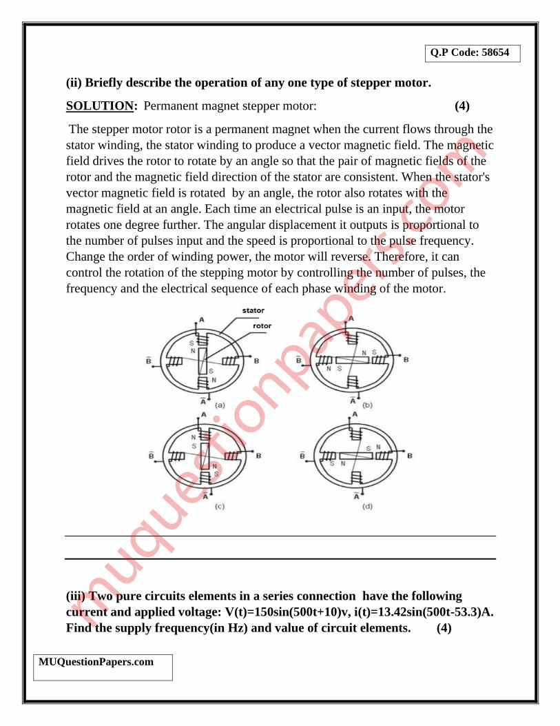
(ii) Briefly describe the operation of any one type of stepper motor.
SOLUTION: Permanent magnet stepper motor: (4)
The stepper motor rotor is a permanent magnet when the current flows through the
stator winding, the stator winding to produce a vector magnetic field. The magnetic
field drives the rotor to rotate by an angle so that the pair of magnetic fields of the
rotor and the magnetic field direction of the stator are consistent. When the stator's
vector magnetic field is rotated by an angle, the rotor also rotates with the
magnetic field at an angle. Each time an electrical pulse is an input, the motor
rotates one degree further. The angular displacement it outputs is proportional to
the number of pulses input and the speed is proportional to the pulse frequency.
Change the order of winding power, the motor will reverse. Therefore, it can
control the rotation of the stepping motor by controlling the number of pulses, the
frequency and the electrical sequence of each phase winding of the motor.
(iii) Two pure circuits elements in a series connection have the following
current and applied voltage: V(t)=150sin(500t+10)v, i(t)=13.42sin(500t-53.3)A.
Find the supply frequency(in Hz) and value of circuit elements. (4)
Q.P Code: 58654
MUQuestionPapers.com
SOLUTION: Given V(t)=150sin(500t+10)v and , i(t)=13.42sin(500t-53.4)A
W=500=2𝜋f therefore frequency is f=𝟓𝟎𝟎
𝟐𝝅 = 79.577Hz
We can see that the current lagging the voltage,
V(t) =150∠𝟏𝟎 i(t) =13.42∠-53.4
Impedance Z =(R+JXL) =𝑽(𝒕)
𝒊(𝒕) =
𝟏𝟓𝟎∠𝟏𝟎
𝟏𝟑.𝟒𝟐∠−𝟓𝟑.𝟒 = ( 5+j10)
Resistance = R = 5Ω
And XL=10 wL =10 , therefore Inductance L = 𝟏𝟎
𝟓𝟎𝟎 = 20mH.
(iv) A three phase, three wire, 100V system supplies a balanced delta-
connected load with per phase impedance of 20∠45 ohms. Determine the line
current drawn and active power taken by the load. (4)
SOLUTION: Given Z = 20∠45
Since it is a delta connected load therefore,
Vph = VL = 100V
Iph = 𝐕𝐩𝐡
𝒁 =
𝟏𝟎𝟎
𝟐𝟎∠𝟒𝟓 = 3.535∠ − 𝟒𝟓 A
Line Current IL = √𝟑 × Iph = 6.12∠ − 𝟒𝟓A
Active Power P =√𝟑 VL IL cos(−𝟒𝟓) = 749.54W
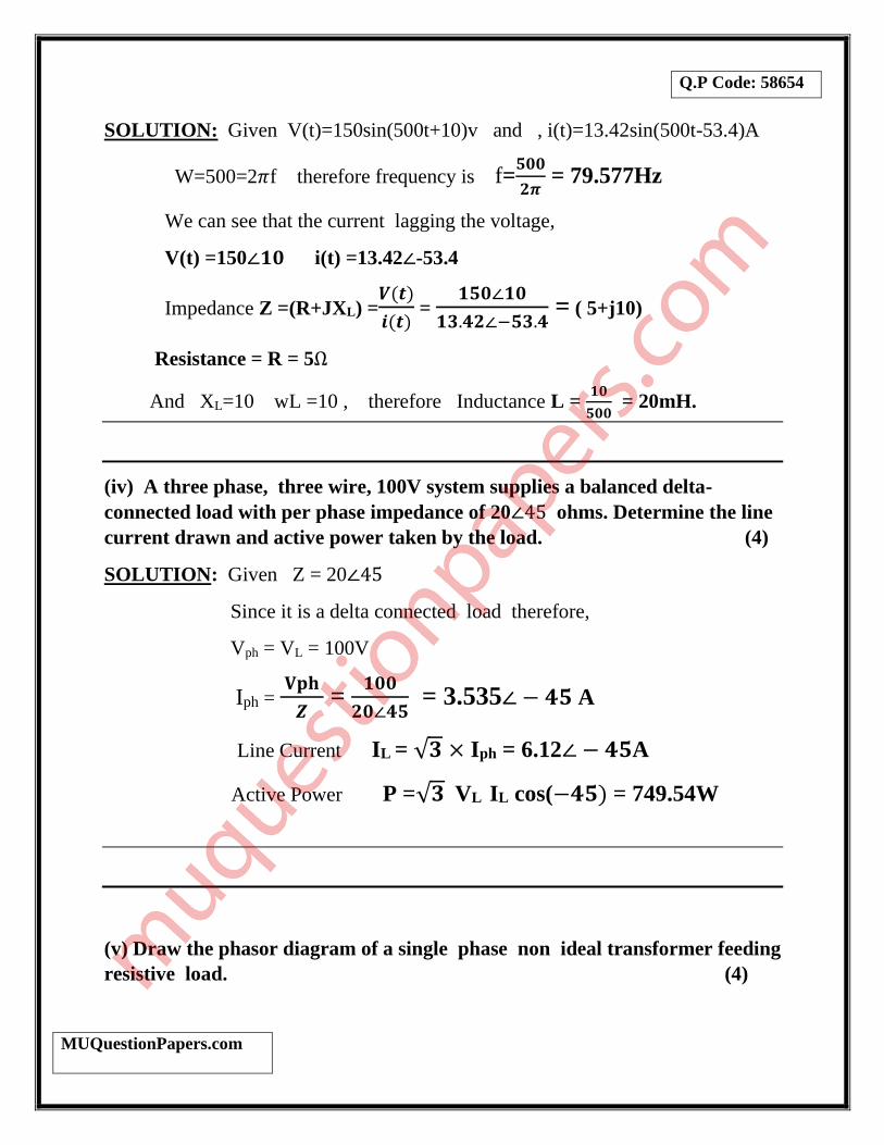
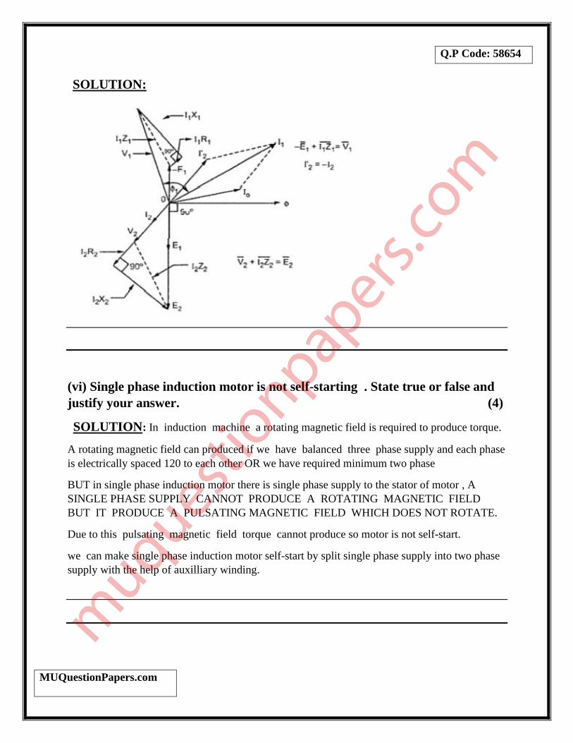
(v) Draw the phasor diagram of a single phase non ideal transformer feeding
resistive load. (4)
Q.P Code: 58654
MUQuestionPapers.com
SOLUTION:
(vi) Single phase induction motor is not self-starting . State true or false and
justify your answer. (4)
SOLUTION: In induction machine a rotating magnetic field is required to produce torque.
A rotating magnetic field can produced if we have balanced three phase supply and each phase
is electrically spaced 120 to each other OR we have required minimum two phase
BUT in single phase induction motor there is single phase supply to the stator of motor , A
SINGLE PHASE SUPPLY CANNOT PRODUCE A ROTATING MAGNETIC FIELD
BUT IT PRODUCE A PULSATING MAGNETIC FIELD WHICH DOES NOT ROTATE.
Due to this pulsating magnetic field torque cannot produce so motor is not self-start.
we can make single phase induction motor self-start by split single phase supply into two phase
supply with the help of auxilliary winding.
Q.P Code: 58654
MUQuestionPapers.com
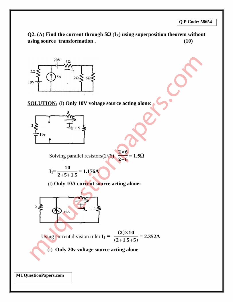
Q2. (A) Find the current through 5Ω (IX) using superposition theorem without
using source transformation . (10)
SOLUTION: (i) Only 10V voltage source acting alone:
Solving parallel resistors(2//6) 𝟐×𝟔
𝟐+𝟔 = 1.5Ω
I1= 𝟏𝟎
𝟐+𝟓+𝟏.𝟓 = 1.176A
(i) Only 10A current source acting alone:
Using current division rule: I2 = (𝟐)×𝟏𝟎
(𝟐+𝟏.𝟓+𝟓) = 2.352A
(i) Only 20v voltage source acting alone:
Q.P Code: 58654
MUQuestionPapers.com
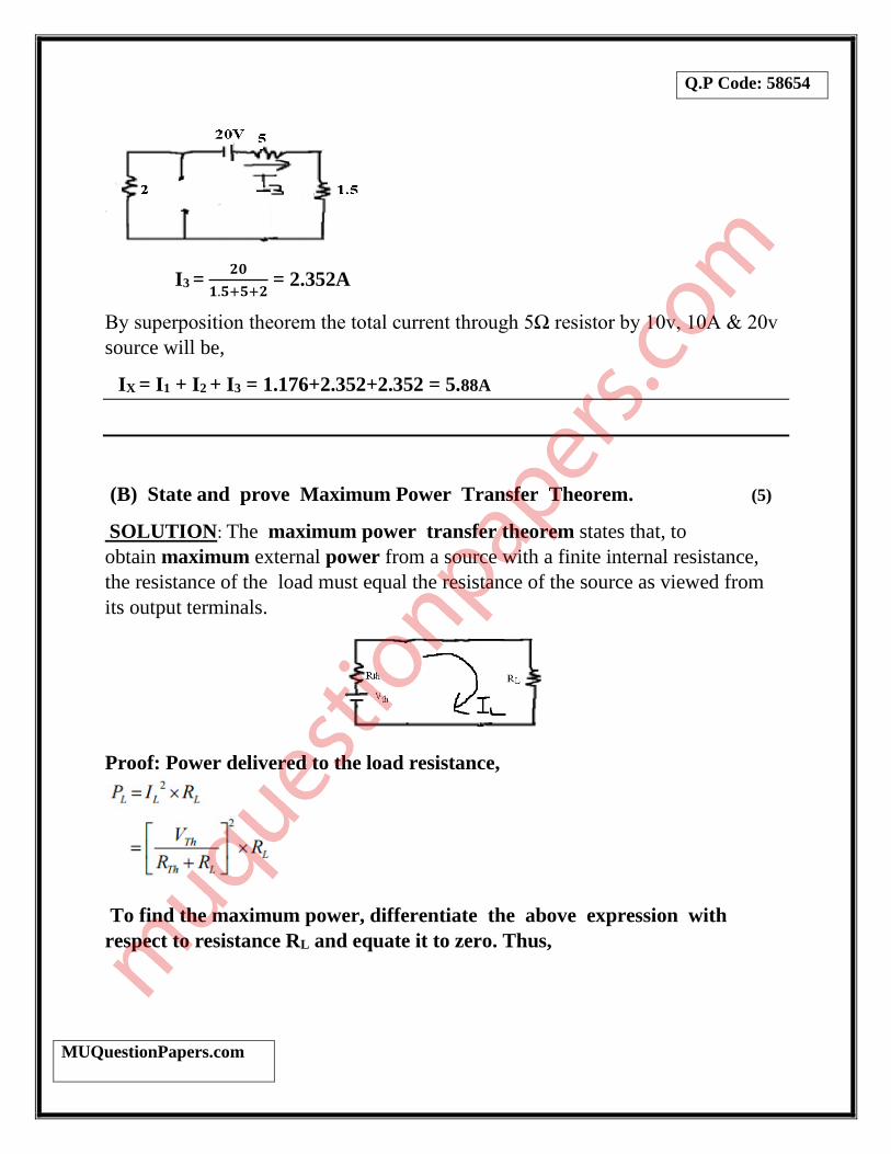
I3 = 𝟐𝟎
𝟏.𝟓+𝟓+𝟐 = 2.352A
By superposition theorem the total current through 5Ω resistor by 10v, 10A & 20v
source will be,
IX = I1 + I2 + I3 = 1.176+2.352+2.352 = 5.88A
(B) State and prove Maximum Power Transfer Theorem. (5)
SOLUTION: The maximum power transfer theorem states that, to
obtain maximum external power from a source with a finite internal resistance,
the resistance of the load must equal the resistance of the source as viewed from
its output terminals.
Proof: Power delivered to the load resistance,
To find the maximum power, differentiate the above expression with
respect to resistance RL and equate it to zero. Thus,

Q.P Code: 58654
MUQuestionPapers.com
The maximum power delivered to the load is,
Thus in this case, the maximum power will be transferred to the load when load
resistance is just equal to internal resistance of the battery.
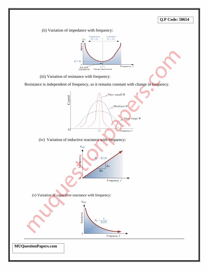
(C) Plot the variation of current, impedance, resistance, inductive reactance
and capacitive reactance when supply frequency is varied in R-L-C series
circuit. (5)
SOLUTION:
(i) Variation of current with frequency:
Q.P Code: 58654
MUQuestionPapers.com
(ii) Variation of impedance with frequency:
(iii) Variation of resistance with frequency:
Resistance is independent of frequency, so it remains constant with change in frequency.
(iv) Variation of inductive reactance with frequency:
(v) Variation of capacitive reactance with frequency:
Q.P Code: 58654
MUQuestionPapers.com
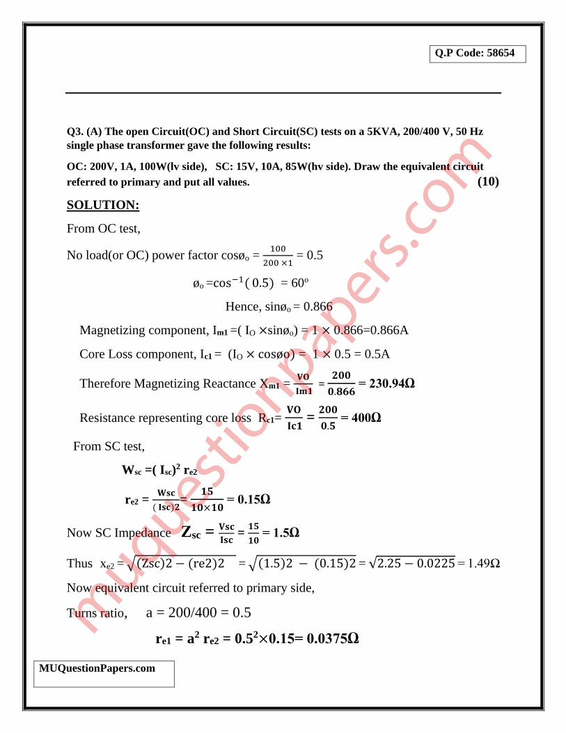
Q3. (A) The open Circuit(OC) and Short Circuit(SC) tests on a 5KVA, 200/400 V, 50 Hz
single phase transformer gave the following results:
OC: 200V, 1A, 100W(lv side), SC: 15V, 10A, 85W(hv side). Draw the equivalent circuit
referred to primary and put all values. (10)
SOLUTION:
From OC test,
No load(or OC) power factor cosøo = 100
200 ×1 = 0.5
øo =cos−1( 0.5) = 60o
Hence, sinøo = 0.866
Magnetizing component, Im1 =( IO ×sinøo) = 1 × 0.866=0.866A
Core Loss component, Ic1 = (IO × cosøo) = 1 × 0.5 = 0.5A
Therefore Magnetizing Reactance Xm1 = 𝐕𝐎
𝐈𝐦𝟏 =
𝟐𝟎𝟎
𝟎.𝟖𝟔𝟔 = 230.94Ω
Resistance representing core loss Rc1= 𝐕𝐎
𝐈𝐜𝟏 =
𝟐𝟎𝟎
𝟎.𝟓 = 400Ω
From SC test,
Wsc =( Isc)2 re2
re2 = 𝐖𝐬𝐜
( 𝐈𝐬𝐜)𝟐=
𝟏𝟓
𝟏𝟎×𝟏𝟎 = 0.15Ω
Now SC Impedance Zsc = 𝐕𝐬𝐜
𝐈𝐬𝐜 =
𝟏𝟓
𝟏𝟎 = 1.5Ω
Thus xe2 = √(Zsc)2 − (re2)2 = √(1.5)2 − (0.15)2 = √2.25 − 0.0225 = 1.49Ω
Now equivalent circuit referred to primary side,
Turns ratio, a = 200/400 = 0.5
re1 = a2 re2 = 0.52×0.15= 0.0375Ω

Q.P Code: 58654
MUQuestionPapers.com
xe1= a2 xe2 = 0.52×1.49=0.3725Ω
Equivalent circuit referred to primary side
(B) Derive the EMF equation of DC motor. (5)
SOLUTION:
Let
Ф - flux/ pole in weber
Z – Total number of armature conductors.
P - Number of poles
A - Number of parallel paths in armature
N - Speed of armature in r.p.m
Flux cut by one conductor = dФ = PФ
Time taken to complete one revolution = dt = 60/N seconds
Average induced E.M.F in one conductor = e = PФ/dt
e = PФN/60 Volt
Number of conductors connected in series in each parallel path = Z/A
Average induced EMF across each parallel path that is across armature
terminals,
Q.P Code: 58654
MUQuestionPapers.com
E = e *Z/A
= (PФN/60) *Z/A
E = (ФZN/60)* P/A
For a wave wound machine A = 2
E = ФZNP/120 Volt
Lap wound machine A =P
E = ФZN/60 Volt
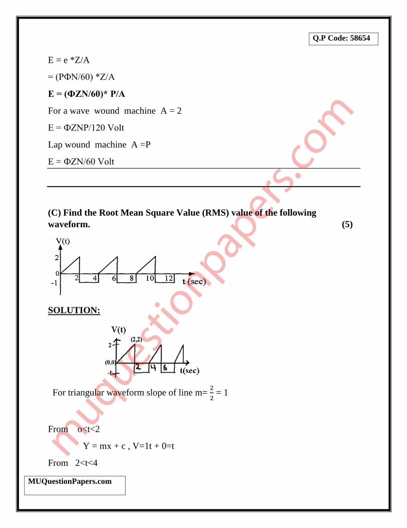
(C) Find the Root Mean Square Value (RMS) value of the following
waveform. (5)
SOLUTION:
For triangular waveform slope of line m= 2
2 = 1
From o<t<2
Y = mx + c , V=1t + 0=t
From 2<t<4
Q.P Code: 58654
MUQuestionPapers.com
V= -1
∫ 𝑣4
02(t) = ∫ 𝑡
2
02dt + ∫ (−1)
4
22dt = [
𝑡3
3]0
2 + [1]24 =(
8
3 + 2) = 4.67
Vrms = √𝑨𝒓𝒆𝒂 𝒐𝒇 𝑾𝒂𝒗𝒆𝒇𝒐𝒓𝒎 𝒐𝒗𝒆𝒓 𝒇𝒖𝒍𝒍 𝒄𝒚𝒄𝒍𝒆
𝑷𝒆𝒓𝒊𝒐𝒅 𝒐𝒇 𝒕𝒉𝒆 𝒘𝒂𝒗𝒆𝒇𝒐𝒓𝒎 = √
𝟒.𝟔𝟕
𝟒 = √𝟏. 𝟏𝟔𝟕 = 1.08V
Q4. (A)With a neat circuit diagram and phasor diagram, prove that by two
wattmeter method active power and reactive power of a three phase load can
be measured. (10)
SOLUTION:
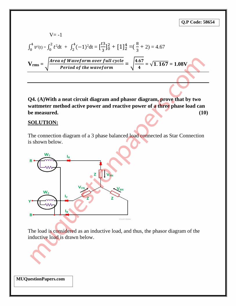
The connection diagram of a 3 phase balanced load connected as Star Connection
is shown below.
The load is considered as an inductive load, and thus, the phasor diagram of the
inductive load is drawn below.
Q.P Code: 58654
MUQuestionPapers.com
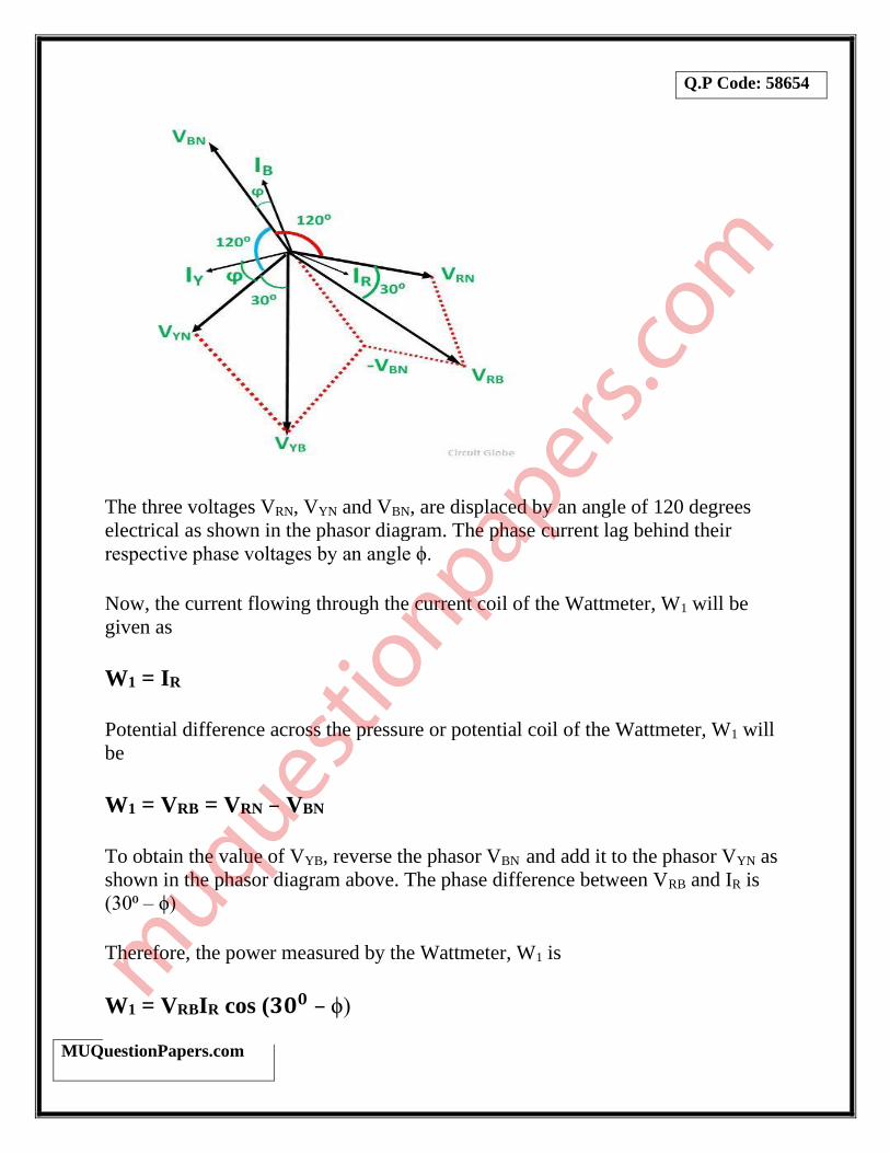
The three voltages VRN, VYN and VBN, are displaced by an angle of 120 degrees
electrical as shown in the phasor diagram. The phase current lag behind their
respective phase voltages by an angle ϕ.
Now, the current flowing through the current coil of the Wattmeter, W1 will be
given as
W1 = IR
Potential difference across the pressure or potential coil of the Wattmeter, W1 will
be
W1 = VRB = VRN – VBN
To obtain the value of VYB, reverse the phasor VBN and add it to the phasor VYN as
shown in the phasor diagram above. The phase difference between VRB and IR is
(30⁰ – ϕ)
Therefore, the power measured by the Wattmeter, W1 is
W1 = VRBIR cos (𝟑𝟎𝟎 – ϕ)

Q.P Code: 58654
MUQuestionPapers.com
Current through the current coil of the Wattmeter, W2 is given as
W2 = IY
Potential difference across the Wattmeter, W2 is
W2 = VYB = VRN – VBN
The phase difference VYB and IY is (30⁰ + ϕ).
Therefore, the power measured by the Wattmeter, W2 is given by the equation
shown below.
W2 = VYBIY cos (𝟑𝟎𝟎 + ϕ)
Since, the load is in balanced condition, hence,
IR = IY = IB = IL and
VRY = VYB = VBR = VL
Therefore, the wattmeter readings will be
W1 = VLIL cos (𝟑𝟎𝟎 – ϕ) and
W2 = VLIL cos (𝟑𝟎𝟎 + ϕ)
Now, the sum of two Wattmeter readings will be given as
W1 + W2 = [VLIL cos (𝟑𝟎𝟎 – ϕ) + VLIL cos (𝟑𝟎𝟎 + ϕ)]
W1 + W2 = VLIL[cos𝟑𝟎𝟎 cos ϕ + sin𝟑𝟎𝟎 sin ϕ
+ 𝐜𝐨𝐬𝟑𝟎𝟎 𝐜𝐨𝐬 𝛟 – 𝐬𝐢𝐧𝟑𝟎𝟎 𝐬𝐢𝐧 𝛟 ]
W1 + W2 = VLIL(2 𝐜𝐨𝐬𝟑𝟎𝟎 𝐜𝐨𝐬 𝛟 )
Q.P Code: 58654
MUQuestionPapers.com
W1 + W2 = VLIL(2√𝟑
𝟐 𝐜𝐨𝐬 𝛟)
W1 + W2 = √𝟑VLIL𝐜𝐨𝐬 𝛟 = P ………….(1)
The above equation (1) gives the Active power absorbed by a 3 phase balanced
load.
As we know that,
W1 + W2 = √𝟑VLIL𝐜𝐨𝐬 𝛟
Now,
W1 – W2 = [VLIL cos (𝟑𝟎𝟎 – ϕ) – VLIL cos (𝟑𝟎𝟎 + ϕ)]
W1 – W2 = VLIL[cos𝟑𝟎𝟎 cos ϕ + sin𝟑𝟎𝟎 sin ϕ
– 𝐜𝐨𝐬𝟑𝟎𝟎 𝐜𝐨𝐬 𝛟 + 𝐬𝐢𝐧𝟑𝟎𝟎 𝐬𝐢𝐧 𝛟 ]
W1 – W2 = 2VLIL 𝐬𝐢𝐧𝟑𝟎𝟎 𝐬𝐢𝐧 𝛟
W1 – W2 = VLIL 𝐬𝐢𝐧 𝛟 ……………(2)
Determination of Reactive Power by Two Wattmeter Method
To get the reactive power, multiply equation (2) by √3
√𝟑 (W1 – W2) = √𝟑VLIL 𝐬𝐢𝐧 𝛟 = Pr
Therefore, the Reactive Power is given by the equation shown below.
Pr = √𝟑 (W1 – W2)
Q.P Code: 58654
MUQuestionPapers.com
(B) A sinusoidal voltage v(t)=200sin(wt) is applied to a series R-L-C circuit
with R=20Ω, l=100mH, and C=10µF. Find (i) the resonant frequency, (ii)
RMS value of current at resonance (iii) Quality factor of the circuit, (iv)
voltage across the inductor at resonance frequency and (v) phasor diagram at
resonance. (10)
SOLUTION: L=100mH = 100×10-3 = 0.1H
C=10µF=10× 𝟏𝟎-6=10-5
(i) The resonant frequency fo = 𝟏
𝟐𝝅√
𝟏
𝑳𝑪 =
𝟏
𝟐𝝅√
𝟏
𝟎.𝟏×𝟏𝟎−𝟓 = 159.15Hz
(ii) At resonance (XL – XC)2 = 0 , Z=√𝐑𝟐 + (𝑿𝑳– 𝑿𝑪)𝟐 = R
Irms = 𝑽
𝒁 =
𝟐𝟎𝟎
𝟐𝟎 = 10A
(iii) Q factor = 𝑾×𝑳
𝑹 =
𝟐𝛑×𝟏𝟓𝟗.𝟏𝟓×𝟎.𝟏
𝟐𝟎 = 5
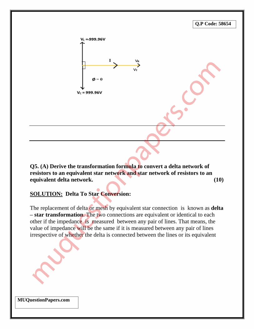
(iv) At resonance, the voltage across the inductor is,
VL= IrmsXL = (10) × (2𝜋 × 159.15) × (0.1) = 999.96V
(v) At resonance XL = XC and VL = VC = 999.96V And circuit becomes
Resistive . And phase difference between voltage and current will be zero i.e
(ø = 0) such that V(t) = VT = VR = 200V .
Q.P Code: 58654
MUQuestionPapers.com
Q5. (A) Derive the transformation formula to convert a delta network of
resistors to an equivalent star network and star network of resistors to an
equivalent delta network. (10)
SOLUTION: Delta To Star Conversion:
The replacement of delta or mesh by equivalent star connection is known as delta
– star transformation. The two connections are equivalent or identical to each
other if the impedance is measured between any pair of lines. That means, the
value of impedance will be the same if it is measured between any pair of lines
irrespective of whether the delta is connected between the lines or its equivalent

Q.P Code: 58654
MUQuestionPapers.com
star is connected between that lines.
Consider a delta system that’s three corner points are A, B and C as shown in the
figure. Electrical resistance of the branch between points A and B, B and C and C
and A are R1, R2 and R3 respectively.
RAB = R1 || (R2 + R3) = 𝑹𝟏.(𝑹𝟐 + 𝑹𝟑)
𝑹𝟏+ 𝑹𝟐+ 𝑹𝟑
Now, one star system is connected to these points A, B, and C as shown in the
figure. Three arms RA, RB and RC of the star system are connected with A, B and C
respectively. Now if we measure the resistance value between points A and B, we
will get,
RAB = RA + RB Since the two systems are identical, resistance measured between terminals A and
B in both systems must be equal.
RA + RB = 𝑹𝟏.(𝑹𝟐+𝑹𝟑)
𝑹𝟏+𝑹𝟐+𝑹𝟑 ………..(i)
Similarly, resistance between points B and C being equal in the two systems,
RB+ RC = 𝑹𝟐.(𝑹𝟑+𝑹𝟏)
𝑹𝟏+𝑹𝟐+𝑹𝟑 ……….. (ii)
Q.P Code: 58654
MUQuestionPapers.com
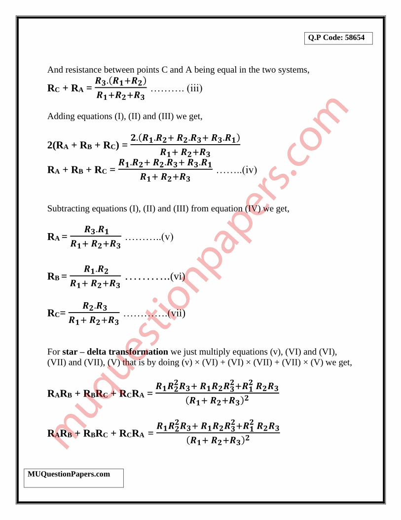
And resistance between points C and A being equal in the two systems,
RC + RA = 𝑹𝟑.(𝑹𝟏+𝑹𝟐)
𝑹𝟏+𝑹𝟐+𝑹𝟑 ………. (iii)
Adding equations (I), (II) and (III) we get,
2(RA + RB + RC) = 𝟐.(𝑹𝟏.𝑹𝟐+ 𝑹𝟐.𝑹𝟑+ 𝑹𝟑.𝑹𝟏)
𝑹𝟏+ 𝑹𝟐+𝑹𝟑
RA + RB + RC = 𝑹𝟏.𝑹𝟐+ 𝑹𝟐.𝑹𝟑+ 𝑹𝟑.𝑹𝟏
𝑹𝟏+ 𝑹𝟐+𝑹𝟑 ……..(iv)
Subtracting equations (I), (II) and (III) from equation (IV) we get,
RA = 𝑹𝟑.𝑹𝟏
𝑹𝟏+ 𝑹𝟐+𝑹𝟑 ………..(v)
RB = 𝑹𝟏.𝑹𝟐
𝑹𝟏+ 𝑹𝟐+𝑹𝟑 ………..(vi)
RC= 𝑹𝟐.𝑹𝟑
𝑹𝟏+ 𝑹𝟐+𝑹𝟑 ………….(vii)
For star – delta transformation we just multiply equations (v), (VI) and (VI),
(VII) and (VII), (V) that is by doing (v) × (VI) + (VI) × (VII) + (VII) × (V) we get,
RARB + RBRC + RCRA = 𝑹𝟏𝑹𝟐
𝟐𝑹𝟑+ 𝑹𝟏𝑹𝟐𝑹𝟑𝟐+𝑹𝟏
𝟐 𝑹𝟐𝑹𝟑
(𝑹𝟏+ 𝑹𝟐+𝑹𝟑)𝟐
RARB + RBRC + RCRA = 𝑹𝟏𝑹𝟐
𝟐𝑹𝟑+ 𝑹𝟏𝑹𝟐𝑹𝟑𝟐+𝑹𝟏
𝟐 𝑹𝟐𝑹𝟑
(𝑹𝟏+ 𝑹𝟐+𝑹𝟑)𝟐
Q.P Code: 58654
MUQuestionPapers.com
= 𝑹𝟏𝑹𝟐𝑹𝟑(𝑹𝟏+ 𝑹𝟐+𝑹𝟑)
(𝑹𝟏+ 𝑹𝟐+𝑹𝟑)𝟐
= 𝑹𝟏𝑹𝟐𝑹𝟑
𝑹𝟏+ 𝑹𝟐+𝑹𝟑 …….. (viii)
Now dividing equation (VIII) by equations (V), (VI) and equations (VII)
separately we get,
R2 = 𝑹𝑨𝑹𝑩+ 𝑹𝑩𝑹𝑪+ 𝑹𝑪𝑹𝑨
𝑹𝑨
R3 = 𝑹𝑨𝑹𝑩+ 𝑹𝑩𝑹𝑪+ 𝑹𝑪𝑹𝑨
𝑹𝑩
R1 = 𝑹𝑨𝑹𝑩+ 𝑹𝑩𝑹𝑪+ 𝑹𝑪𝑹𝑨
𝑹𝑪
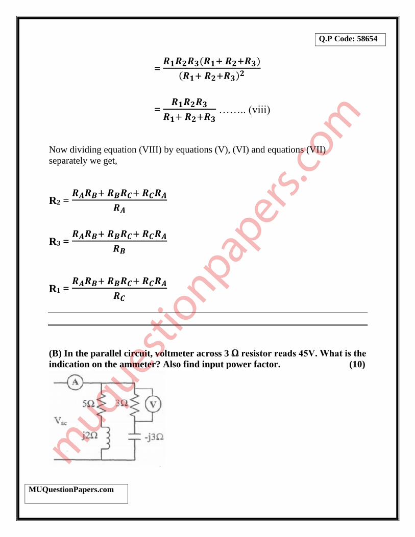
(B) In the parallel circuit, voltmeter across 3 Ω resistor reads 45V. What is the
indication on the ammeter? Also find input power factor. (10)
Q.P Code: 58654
MUQuestionPapers.com
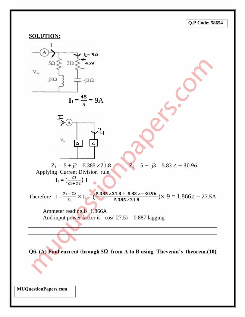
SOLUTION:
I1 = 𝟒𝟓
𝟓 = 9A
Z1 = 5 + j2 = 5.385 ∠21.8 , Z2 = 5 − j3 = 5.83 ∠ − 30.96
Applying Current Division rule,
I1 = (Z1
Z1+ Z2) I
Therefore I = Z1+ Z2
Z1× I1 = (
𝟓.𝟑𝟖𝟓 ∠𝟐𝟏.𝟖 + 𝟓.𝟖𝟑 ∠−𝟑𝟎.𝟗𝟔
𝟓.𝟑𝟖𝟓 ∠𝟐𝟏.𝟖)× 9 = 1.866∠ − 27.5A
Ammeter reading is 1.866A
And input power factor is cos(-27.5) = 0.887 lagging
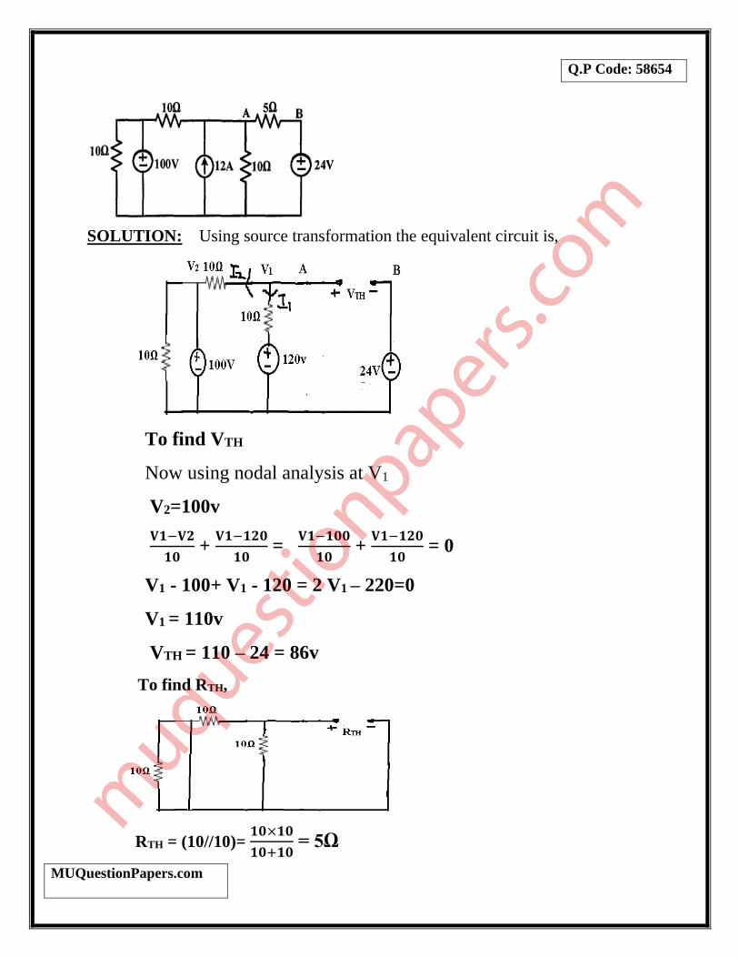
Q6. (A) Find current through 5Ω from A to B using Thevenin’s theorem.(10)
Q.P Code: 58654
MUQuestionPapers.com
SOLUTION: Using source transformation the equivalent circuit is,
To find VTH
Now using nodal analysis at V1
V2=100v
𝐕𝟏−𝐕𝟐
𝟏𝟎 +
𝐕𝟏−𝟏𝟐𝟎
𝟏𝟎 =
𝐕𝟏−𝟏𝟎𝟎
𝟏𝟎 +
𝐕𝟏−𝟏𝟐𝟎
𝟏𝟎 = 0
V1 - 100+ V1 - 120 = 2 V1 – 220=0
V1 = 110v
VTH = 110 – 24 = 86v
To find RTH,
RTH = (10//10)= 𝟏𝟎×𝟏𝟎
𝟏𝟎+𝟏𝟎 = 5Ω

Q.P Code: 58654
MUQuestionPapers.com
The Thevenin’s equivalent circuit,
The current through 5Ω Resistor will be,
I5Ω = 𝟖𝟔
𝟓+𝟓 = 8.6A
(B) A 20KVA Transformer has iron loss of 450W and full load copper loss of
900W. Assume power factor of load as 0.8 lagging. Find full load and half
load efficiency of the transformer. (5)
SOLUTION: Given Wi = 450W, Wcu = 900W
At full load x = 1
%ɳ = (𝒙×𝒇𝒖𝒍𝒍−𝒍𝒐𝒂𝒅 𝑲𝑽𝑨×𝒑𝒇)
(𝒙×𝒇𝒖𝒍𝒍−𝒍𝒐𝒂𝒅 𝑲𝑽𝑨×𝒑𝒇)+𝑾𝒊+𝒙𝟐[𝑾𝒄𝒖] × 𝟏𝟎𝟎
= (𝟏×𝟐𝟎×𝟎.𝟖)
(𝟏×𝟐𝟎×𝟎.𝟖)+𝟎.𝟒𝟓+𝟏𝟐×𝟎.𝟗 × 𝟏𝟎𝟎 = 92.21%
At half load x = 0.5,
%ɳ = (𝟎.𝟓×𝟐𝟎×𝟎.𝟖)
(𝟎.𝟓×𝟐𝟎×𝟎.𝟖)+𝟎.𝟒𝟓+𝟎.𝟓𝟐×𝟎.𝟗 × 𝟏𝟎𝟎 = 83.33%

Q.P Code: 58654
MUQuestionPapers.com
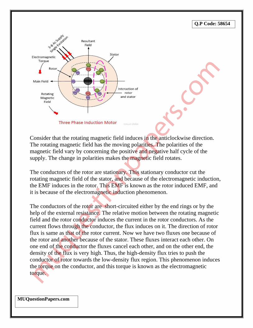
(C) Briefly explain the principle of operation of three phase induction motor.
What are the types of three phase induction motor? (5)
SOLUTION:
The motor which works on the principle of electromagnetic induction is known as
the induction motor. The electromagnetic induction is the phenomenon in which
the electromotive force induces across the electrical conductor when it is placed in
a rotating magnetic field.
The stator and rotor are two essential parts of the motor. The stator is the stationary
part, and it carries the overlapping windings while the rotor carries the main or
field winding. The windings of the stator are equally displaced from each other by
an angle of 120°.
The induction motor is the single excited motor, i.e., the supply is applied only to
the one part, i.e., stator. The term excitation means the process of inducing the
magnetic field on the parts of the motor.
When the three phase supply is given to the stator, the rotating magnetic field
produced on it. The figure below shows the rotating magnetic field set up in the
stator.
Q.P Code: 58654
MUQuestionPapers.com
Consider that the rotating magnetic field induces in the anticlockwise direction.
The rotating magnetic field has the moving polarities. The polarities of the
magnetic field vary by concerning the positive and negative half cycle of the
supply. The change in polarities makes the magnetic field rotates.
The conductors of the rotor are stationary. This stationary conductor cut the
rotating magnetic field of the stator, and because of the electromagnetic induction,
the EMF induces in the rotor. This EMF is known as the rotor induced EMF, and
it is because of the electromagnetic induction phenomenon.
The conductors of the rotor are short-circuited either by the end rings or by the
help of the external resistance. The relative motion between the rotating magnetic
field and the rotor conductor induces the current in the rotor conductors. As the
current flows through the conductor, the flux induces on it. The direction of rotor
flux is same as that of the rotor current. Now we have two fluxes one because of
the rotor and another because of the stator. These fluxes interact each other. On
one end of the conductor the fluxes cancel each other, and on the other end, the
density of the flux is very high. Thus, the high-density flux tries to push the
conductor of rotor towards the low-density flux region. This phenomenon induces
the torque on the conductor, and this torque is known as the electromagnetic
torque.

Q.P Code: 58654
MUQuestionPapers.com
The direction of electromagnetic torque and rotating magnetic field is same. Thus,
the rotor starts rotating in the same direction as that of the rotating magnetic field.
There are two types of 3 phase Induction motors,
• Squirrel Cage Induction Motor.
• Slip Ring Induction Motor or Wound Rotor Induction
Motor or Phase Wound Induction Motor.