Embed Size (px)
Citation preview
BEDJOINTS STRUCTURAL REPOINTING OF HISTORIC MASONRY STRUCTURES
L. Binda 1, C. Modena 2, A. Saisi 1, R. Tongini Folli 1, M.R. Valluzzi 2
ABSTRACT The serious risks of failure of historic masonry structures when subjected for long time to very high compressive stresses (i.e. 50 to 70 % of the experimental peak stress) have been recognised following recent collapses. The authors classified several cases where this situation occurs: they actually represent a relevant part of the architectural heritage, being typically towers (bell and civic), pillars of churches and buildings supporting vaults and domes and fortification walls. The current repair/strengthening techniques proved to be in such cases substantially ineffective (this is the case for example of injections and of local reconstruction) or excessively invasive. What is really needed in fact, in the authors opinion, is rather than increase the compressive strength of masonry, to improve its response to long term actions by counteracting the “damaging” phenomenon of the progressively developing “diffused” cracks (creep like behaviour). In this respect, the authors suggest a global improvement by tie roads and locally the insertion of reinforcement in bed joints. This repair technique is already in use for other purposes, typically to counteract expansion cracks in facing clay masonry walls in northern European countries, and can be successfully used to control the cracks formation and development of highly compressed masonry. Preliminary laboratory tests that have been already carried out on wallettes subjected to monotonic loading and loading by steps of constant load (pseudo creep test), have shown that the above use can fulfil the requirements. Test results and preliminary numerical investigations indicated the way how the intervention can be designed by appropriately choosing the material properties and the dimensions and positions of the strengthening bars. In field applications, subjected to continuos monitoring of the cracks width after the intervention, already demonstrated the feasibility of the techniques and his positive effects. Based on the previous consideration a systematic investigation has been started, in order to study more in detail the effect of a repair technique, specifically finalised to the dilation control, in the long term mechanical damage of the masonry. The above research and field application experiences are presented and commented. Key words : brick masonry, creep behaviour, bed joint reinforcement, experimental tests 1 Dipartimento di Ingegneria Strutturale, Politecnico di Milano, Piazzale L. da Vinci 32, 20133 Milano, [email protected], [email protected], [email protected] 2 Dipartimento di Costruzioni e Trasporti, Università di Padova, via Marzolo 9, 35131 Padova, [email protected] , [email protected]
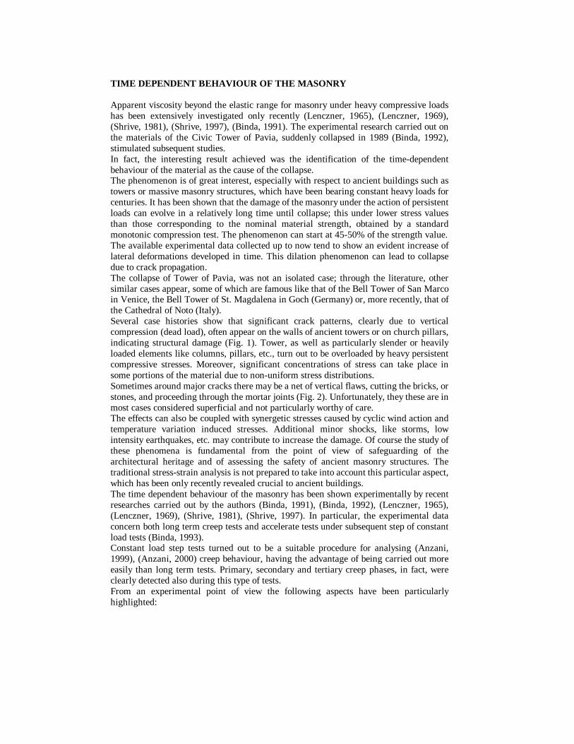
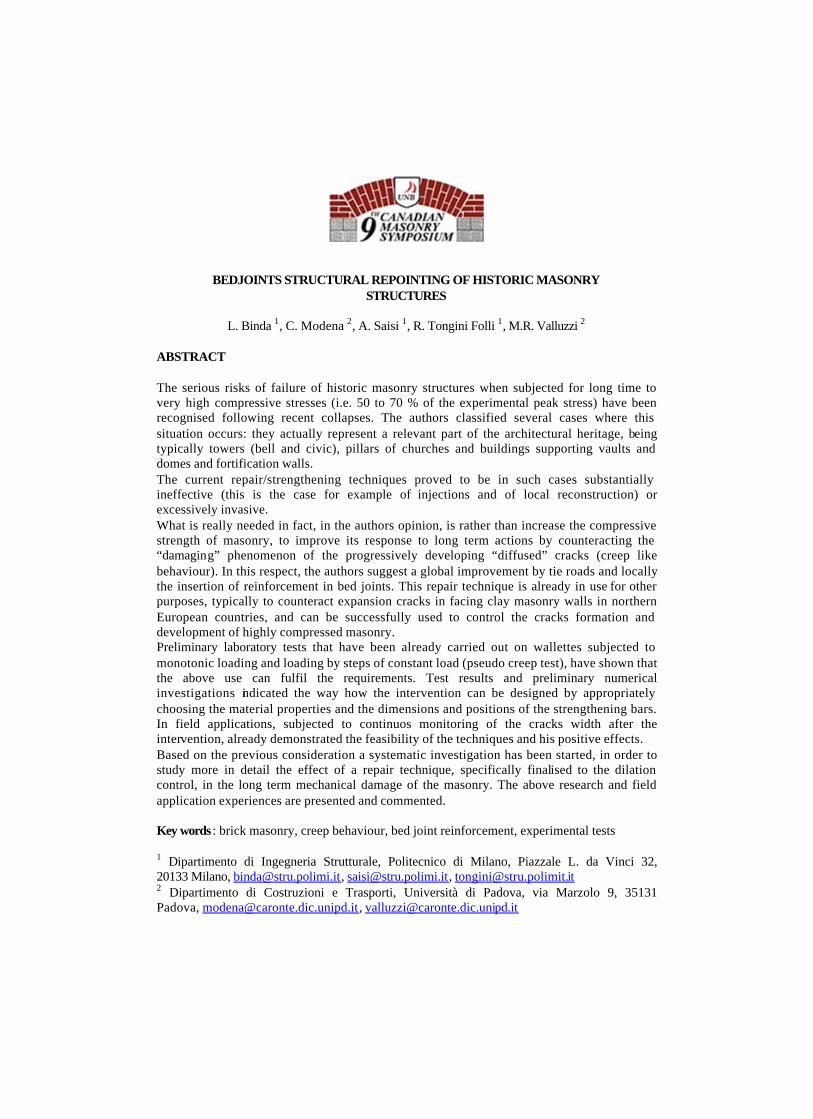
TIME DEPENDENT BEHAVIOUR OF THE MASONRY Apparent viscosity beyond the elastic range for masonry under heavy compressive loads has been extensively investigated only recently (Lenczner, 1965), (Lenczner, 1969), (Shrive, 1981), (Shrive, 1997), (Binda, 1991). The experimental research carried out on the materials of the Civic Tower of Pavia, suddenly collapsed in 1989 (Binda, 1992), stimulated subsequent studies. In fact, the interesting result achieved was the identification of the time-dependent behaviour of the material as the cause of the collapse. The phenomenon is of great interest, especially with respect to ancient buildings such as towers or massive masonry structures, which have been bearing constant heavy loads for centuries. It has been shown that the damage of the masonry under the action of persistent loads can evolve in a relatively long time until collapse; this under lower stress values than those corresponding to the nominal material strength, obtained by a standard monotonic compression test. The phenomenon can start at 45-50% of the strength value. The available experimental data collected up to now tend to show an evident increase of lateral deformations developed in time. This dilation phenomenon can lead to collapse due to crack propagation. The collapse of Tower of Pavia, was not an isolated case; through the literature, other similar cases appear, some of which are famous like that of the Bell Tower of San Marco in Venice, the Bell Tower of St. Magdalena in Goch (Germany) or, more recently, that of the Cathedral of Noto (Italy). Several case histories show that significant crack patterns, clearly due to vertical compression (dead load), often appear on the walls of ancient towers or on church pillars, indicating structural damage (Fig. 1). Tower, as well as particularly slender or heavily loaded elements like columns, pillars, etc., turn out to be overloaded by heavy persistent compressive stresses. Moreover, significant concentrations of stress can take place in some portions of the material due to non-uniform stress distributions. Sometimes around major cracks there may be a net of vertical flaws, cutting the bricks, or stones, and proceeding through the mortar joints (Fig. 2). Unfortunately, they these are in most cases considered superficial and not particularly worthy of care. The effects can also be coupled with synergetic stresses caused by cyclic wind action and temperature variation induced stresses. Additional minor shocks, like storms, low intensity earthquakes, etc. may contribute to increase the damage. Of course the study of these phenomena is fundamental from the point of view of safeguarding of the architectural heritage and of assessing the safety of ancient masonry structures. The traditional stress-strain analysis is not prepared to take into account this particular aspect, which has been only recently revealed crucial to ancient buildings. The time dependent behaviour of the masonry has been shown experimentally by recent researches carried out by the authors (Binda, 1991), (Binda, 1992), (Lenczner, 1965), (Lenczner, 1969), (Shrive, 1981), (Shrive, 1997). In particular, the experimental data concern both long term creep tests and accelerate tests under subsequent step of constant load tests (Binda, 1993). Constant load step tests turned out to be a suitable procedure for analysing (Anzani, 1999), (Anzani, 2000) creep behaviour, having the advantage of being carried out more easily than long term tests. Primary, secondary and tertiary creep phases, in fact, were clearly detected also during this type of tests. From an experimental point of view the following aspects have been particularly highlighted:
− the material dilation under severe compressive stresses with high values of the horizontal strain developing before failure;
− the development of creep strains depending on the stress level, with secondary creep showing even at the 40% of the estimated material peak stress and possibility that tertiary creep shows at about the 70%;
− a slow crack propagation and failure developing in a relatively long time. This aspect suggests that the evolution of vertical cracks, which might appear on the external walls of a building should be carefully analysed. In fact, the possibility of continuos damage with the consequence of a future sudden collapse cannot be a priori ruled out;
− the combination of cyclic actions with the effect of a heavy dead load turns out to be a particularly critical situation, which is able to induce material damage.
Case history The Bell Tower of the Cathedral of Monza is a XVI century building made of solid brick masonry. Its walls, show passing-through large vertical potentially dangerous cracks on the West and East sides (Fig. 3), which are slowly but continuously opening. These cracks were certainly already present in 1920 since they were roughly monitored in 1927. Wide cracks are also present in the corners of the tower up top 30 m. Furthermore, a damaged zone at a height of 11 to 25 m with a multitude of very thin and diffused vertical cracks is present which demands structure repair (Fig. 4). In order to assess the structural condition of the tower, an in situ investigation using non-destructive and slightly techniques was carried out (Binda, 1998). Laboratory tests were carried out on bricks and mortars. Furthermore masonry specimens
Figure 1. Prospect of a pillar of the Noto Cathedral (Italy) and survey of the crack
pattern
Figure 2. a) Torre Galluzzi, b) Torre Alberici, c) Casa-torre Uguzzoni in
Bologna (Italy) and detail of the crack pattern of Torre Galluzzi
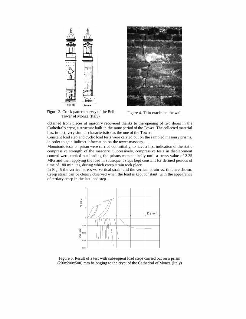
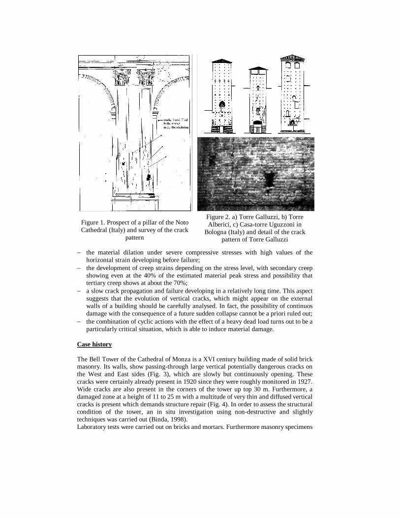
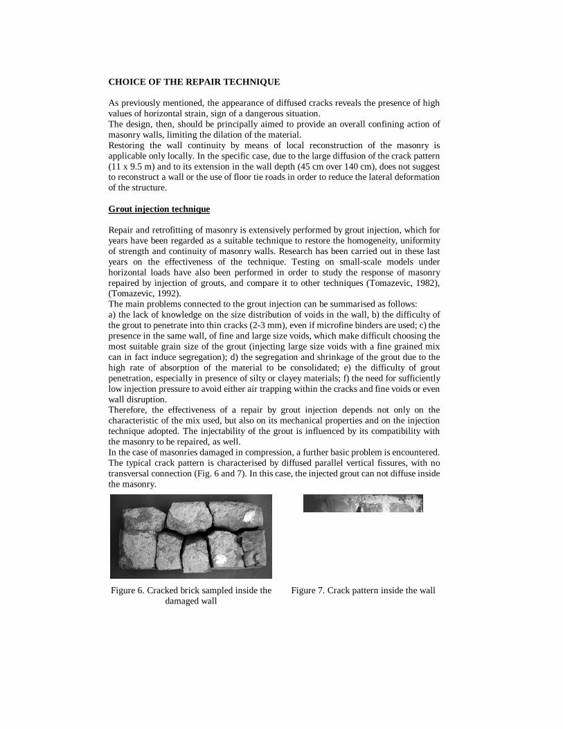
obtained from pieces of masonry recovered thanks to the opening of two doors in the Cathedral's crypt, a structure built in the same period of the Tower. The collected material has, in fact, very similar characteristics as the one of the Tower. Constant load step and cyclic load tests were carried out on the sampled masonry prisms, in order to gain indirect information on the tower masonry. Monotonic tests on prism were carried out initially, to have a first indication of the static compressive strength of the masonry. Successively, compressive tests in displacement control were carried out loading the prisms monotonically until a stress value of 2.25 MPa and then applying the load in subsequent steps kept constant for defined periods of time of 180 minutes, during which creep strain took place. In Fig. 5 the vertical stress vs. vertical strain and the vertical strain vs. time are shown. Creep strain can be clearly observed when the load is kept constant, with the appearance of tertiary creep in the last load step.
Figure 3. Crack pattern survey of the Bell Tower of Monza (Italy)
Figure 4. Thin cracks on the wall
2 4 6 8 10εv ( x 1 0 3)
0
2
4
6
σv
[MP
a]
0
2000
4000
6000
8000
time
[sec
]
Figure 5. Result of a test with subsequent load steps carried out on a prism
(200x200x500) mm belonging to the crypt of the Cathedral of Monza (Italy)
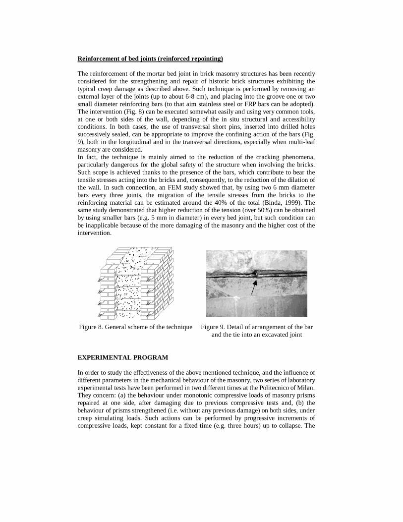
CHOICE OF THE REPAIR TECHNIQUE As previously mentioned, the appearance of diffused cracks reveals the presence of high values of horizontal strain, sign of a dangerous situation. The design, then, should be principally aimed to provide an overall confining action of masonry walls, limiting the dilation of the material. Restoring the wall continuity by means of local reconstruction of the masonry is applicable only locally. In the specific case, due to the large diffusion of the crack pattern (11 x 9.5 m) and to its extension in the wall depth (45 cm over 140 cm), does not suggest to reconstruct a wall or the use of floor tie roads in order to reduce the lateral deformation of the structure. Grout injection technique Repair and retrofitting of masonry is extensively performed by grout injection, which for years have been regarded as a suitable technique to restore the homogeneity, uniformity of strength and continuity of masonry walls. Research has been carried out in these last years on the effectiveness of the technique. Testing on small-scale models under horizontal loads have also been performed in order to study the response of masonry repaired by injection of grouts, and compare it to other techniques (Tomazevic, 1982), (Tomazevic, 1992). The main problems connected to the grout injection can be summarised as follows: a) the lack of knowledge on the size distribution of voids in the wall, b) the difficulty of the grout to penetrate into thin cracks (2-3 mm), even if microfine binders are used; c) the presence in the same wall, of fine and large size voids, which make difficult choosing the most suitable grain size of the grout (injecting large size voids with a fine grained mix can in fact induce segregation); d) the segregation and shrinkage of the grout due to the high rate of absorption of the material to be consolidated; e) the difficulty of grout penetration, especially in presence of silty or clayey materials; f) the need for sufficiently low injection pressure to avoid either air trapping within the cracks and fine voids or even wall disruption. Therefore, the effectiveness of a repair by grout injection depends not only on the characteristic of the mix used, but also on its mechanical properties and on the injection technique adopted. The injectability of the grout is influenced by its compatibility with the masonry to be repaired, as well. In the case of masonries damaged in compression, a further basic problem is encountered. The typical crack pattern is characterised by diffused parallel vertical fissures, with no transversal connection (Fig. 6 and 7). In this case, the injected grout can not diffuse inside the masonry.
Figure 6. Cracked brick sampled inside the damaged wall
Figure 7. Crack pattern inside the wall
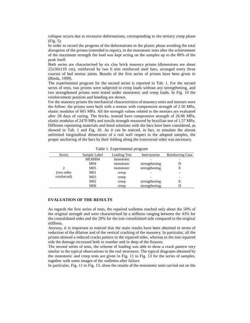
Reinforcement of bed joints (reinforced repointing) The reinforcement of the mortar bed joint in brick masonry structures has been recently considered for the strengthening and repair of historic brick structures exhibiting the typical creep damage as described above. Such technique is performed by removing an external layer of the joints (up to about 6-8 cm), and placing into the groove one or two small diameter reinforcing bars (to that aim stainless steel or FRP bars can be adopted). The intervention (Fig. 8) can be executed somewhat easily and using very common tools, at one or both sides of the wall, depending of the in situ structural and accessibility conditions. In both cases, the use of transversal short pins, inserted into drilled holes successively sealed, can be appropriate to improve the confining action of the bars (Fig. 9), both in the longitudinal and in the transversal directions, especially when multi-leaf masonry are considered. In fact, the technique is mainly aimed to the reduction of the cracking phenomena, particularly dangerous for the global safety of the structure when involving the bricks. Such scope is achieved thanks to the presence of the bars, which contribute to bear the tensile stresses acting into the bricks and, consequently, to the reduction of the dilation of the wall. In such connection, an FEM study showed that, by using two 6 mm diameter bars every three joints, the migration of the tensile stresses from the bricks to the reinforcing material can be estimated around the 40% of the total (Binda, 1999). The same study demonstrated that higher reduction of the tension (over 50%) can be obtained by using smaller bars (e.g. 5 mm in diameter) in every bed joint, but such condition can be inapplicable because of the more damaging of the masonry and the higher cost of the intervention.
Figure 8. General scheme of the technique Figure 9. Detail of arrangement of the bar and the tie into an excavated joint
EXPERIMENTAL PROGRAM In order to study the effectiveness of the above mentioned technique, and the influence of different parameters in the mechanical behaviour of the masonry, two series of laboratory experimental tests have been performed in two different times at the Politecnico of Milan. They concern: (a) the behaviour under monotonic compressive loads of masonry prisms repaired at one side, after damaging due to previous compressive tests and, (b) the behaviour of prisms strengthened (i.e. without any previous damage) on both sides, under creep simulating loads. Such actions can be performed by progressive increments of compressive loads, kept constant for a fixed time (e.g. three hours) up to collapse. The
collapse occurs due to excessive deformations, corresponding to the tertiary creep phase (Fig. 5). In order to record the progress of the deformations in the plastic phase avoiding the total disruption of the prisms (intended to repair), in the monotonic tests after the achievement of the maximum strength the load was kept acting on the samples up to the 80% of the peak itself. Both series are characterised by six clay brick masonry prisms (dimensions are about 25x50x110 cm), reinforced by two 6 mm reinforced steel bars, arranged every three courses of bed mortar joints. Results of the first series of prisms have been given in (Binda, 1999). The experimental program for the second series is reported in Tab. 1. For the second series of tests, two prisms were subjected to creep loads without any strengthening, and two strengthened prisms were tested under monotonic and creep loads. In Fig. 10 the reinforcement position and bonding are shown. For the masonry prisms the mechanical characteristics of masonry units and mortars were the follow: the prisms were built with a mortar with compressive strength of 2.50 MPa, elastic modulus of 665 MPa. All the strength values related to the mortars are evaluated after 28 days of curing. The bricks, instead have compressive strength of 26.86 MPa, elastic modulus of 2470 MPa and tensile strength measured by brazilian test of 1.57 MPa. Different repointing materials and bond solutions with the bars have been considered, as showed in Tab. 1 and Fig. 10. As it can be noticed, in fact, to simulate the almost unlimited longitudinal dimensions of a real wall respect to the adopted samples, the proper anchoring of the bars by their folding along the transversal sides was necessary.
Table 1. Experimental program
Series Sample Label Loading Test Intervention Reinforcing Case MU6H04 monotonic - -
M04 monotonic strengthening D M05 monotonic strengthening E M01 creep - - M03 creep - - M02 creep strengthening E
2 (two sides reinforced)
M06 creep strengthening D EVALUATION OF THE RESULTS As regards the first series of tests, the repaired wallettes reached only about the 50% of the original strength and were characterised by a stiffness ranging between the 43% for the consolidated sides and the 29% for the non consolidated side compared to the original stiffness. Anyway, it is important to noticed that the main results have been obtained in terms of reduction of the dilation and of the vertical cracking of the masonry. In particular, all the prisms showed a reduced cracks pattern in the repaired sides, whereas in the non repaired side the damage increased both in number and in deep of the fissures. The second series of tests, the scheme of loading was able to show a crack pattern very similar to the typical observations in the real structures. The typical diagrams obtained by the monotonic and creep tests are given in Fig. 11 to Fig. 13 for the series of samples, together with some images of the wallettes after failure. In particular, Fig. 11 to Fig. 13. show the results of the monotonic tests carried out on the
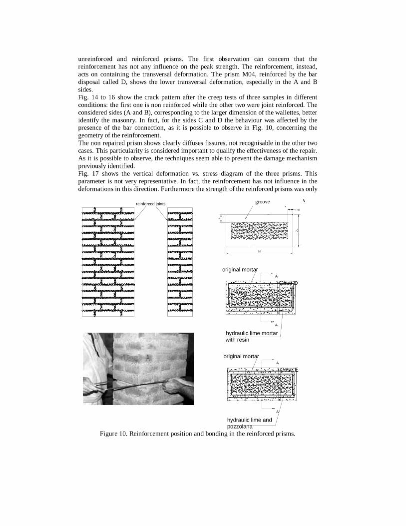
unreinforced and reinforced prisms. The first observation can concern that the reinforcement has not any influence on the peak strength. The reinforcement, instead, acts on containing the transversal deformation. The prism M04, reinforced by the bar disposal called D, shows the lower transversal deformation, especially in the A and B sides. Fig. 14 to 16 show the crack pattern after the creep tests of three samples in different conditions: the first one is non reinforced while the other two were joint reinforced. The considered sides (A and B), corresponding to the larger dimension of the wallettes, better identify the masonry. In fact, for the sides C and D the behaviour was affected by the presence of the bar connection, as it is possible to observe in Fig. 10, concerning the geometry of the reinforcement. The non repaired prism shows clearly diffuses fissures, not recognisable in the other two cases. This particularity is considered important to qualify the effectiveness of the repair. As it is possible to observe, the techniques seem able to prevent the damage mechanism previously identified. Fig. 17 shows the vertical deformation vs. stress diagram of the three prisms. This parameter is not very representative. In fact, the reinforcement has not influence in the deformations in this direction. Furthermore the strength of the reinforced prisms was only
reinforced joints
SCANALATURA MAgrooveSCANALATURA MAgroove
hydraulic lime mortar with resin
A
original mortarA
Case D
A
A
Case E
original mortar
hydraulic lime andpozzolana
Figure 10. Reinforcement position and bonding in the reinforced prisms.
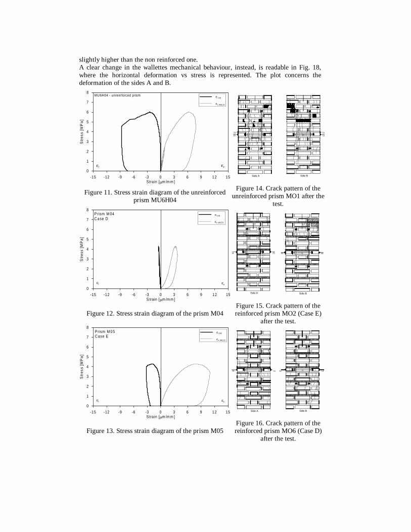
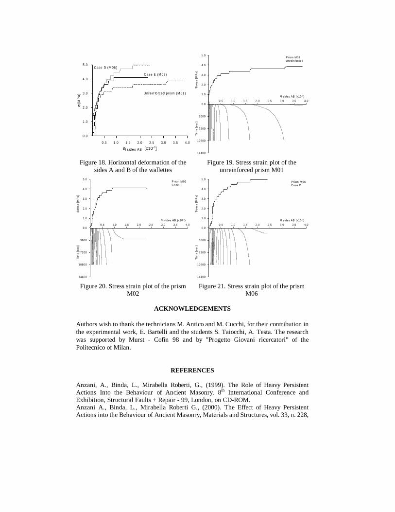
slightly higher than the non reinforced one. A clear change in the wallettes mechanical behaviour, instead, is readable in Fig. 18, where the horizontal deformation vs stress is represented. The plot concerns the deformation of the sides A and B.
-15 -12 -9 -6 -3 0 3 6 9 12 15Stra in [µm /m m ]
0
1
2
3
4
5
6
7
8
Str
ess
[MP
a]
εvεl
εl A B
εv A B C D
MU6H04 - unrein forced prism
Side A Side B
Figure 11. Stress strain diagram of the unreinforced prism MU6H04
Figure 14. Crack pattern of the unreinforced prism MO1 after the
test.
-15 -12 -9 -6 -3 0 3 6 9 12 15S train [µm /m m ]
0
1
2
3
4
5
6
7
8
Str
ess
[MP
a]
εvεl
εl A B
εv A B CD
P rism M 04 C ase D
Side BSide A
Figure 12. Stress strain diagram of the prism M04
Figure 15. Crack pattern of the reinforced prism MO2 (Case E)
after the test.
-15 -12 -9 -6 -3 0 3 6 9 12 15Stra in [µm /m m ]
0
1
2
3
4
5
6
7
8
Str
ess
[MP
a]
εvεl
εl A B
εv AB C D
Prism M 05 C ase E
Side A Side B
Figure 13. Stress strain diagram of the prism M05
Figure 16. Crack pattern of the reinforced prism MO6 (Case D)
after the test.
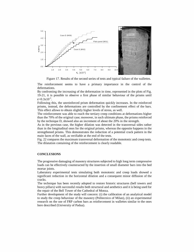
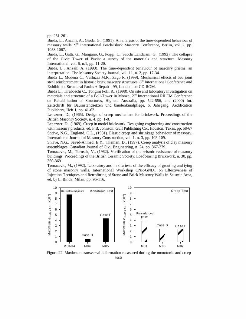
The reinforcement seems to have a primary importance in the control of the deformations. By confronting the increasing of the deformation in time, represented in the plots of Fig. 19-21, it is possible to observe a first phase of similar behaviour of the prisms until ε=0.3x10⁻³. Following this, the unreinforced prism deformation quickly increases. In the reinforced prisms, instead, the deformations are controlled by the confinement effect of the bars. This effect allows to obtain slightly higher levels of stress, as well. The reinforcement was able to reach the tertiary creep conditions at deformations higher than the 70% of the original case; moreover, in such ultimate phase, the prisms reinforced by the technique D, showed also an increment of about the 20% in the strength. As in the previous case, the higher dilation was detected in the transversal sides rather than in the longitudinal ones for the original prisms, whereas the opposite happens in the strengthened prisms. This demonstrates the reduction of a potential crack pattern in the main faces of the wall, as verifiable at the end of the tests. Fig. 22 compares the maximum transversal deformation of the monotonic and creep tests. The dilatation containing of the reinforcement is clearly readable. CONCLUSIONS The progressive damaging of masonry structures subjected to high long term compressive loads can be effectively counteracted by the insertion of small diameter bars into the bed mortar joints. Laboratory experimental tests simulating both monotonic and creep loads showed a significant reduction in the horizontal dilation and a consequent minor diffusion of the cracks. The technique has been recently adopted to restore historic structures (bell towers and heavy pillars) with successful results both structural and aesthetics and it is being used for the repair of the Bell Tower of the Cathedral of Monza. Further development of the study will concern: (i) the calibration of an analytical model to study the creep behaviour of the masonry (Politecnico of Milan), (ii) an experimental research on the use of FRP carbon bars as reinforcement in wallettes similar to the ones here described (University of Padua).
1.0 2.0 3 .0 4 .0 5 .0 6 .0 7.0 8.0 9.0 10 .0
εv [x10 -3]
0 .0
1 .0
2 .0
3 .0
4 .0
5 .0
σ [M
Pa
]
Ca se E (M 0 2)
C as e D (M 06 )
P lain p an el (M 01 )
Figure 17. Results of the second series of tests and typical failure of the wallettes.
ACKNOWLEDGEMENTS
Authors wish to thank the technicians M. Antico and M. Cucchi, for their contribution in the experimental work, E. Bartelli and the students S. Taiocchi, A. Testa. The research was supported by Murst - Cofin 98 and by "Progetto Giovani ricercatori" of the Politecnico of Milan.
REFERENCES
Anzani, A., Binda, L., Mirabella Roberti, G., (1999). The Role of Heavy Persistent Actions Into the Behaviour of Ancient Masonry. 8th International Conference and Exhibition, Structural Faults + Repair - 99, London, on CD-ROM. Anzani A., Binda, L., Mirabella Roberti G., (2000). The Effect of Heavy Persistent Actions into the Behaviour of Ancient Masonry, Materials and Structures, vol. 33, n. 228,
0.5 1.0 1.5 2 .0 2.5 3 .0 3.5 4.0
εl s id e s AB [x10 -3]
0.0
1.0
2.0
3.0
4.0
5.0
σ [M
Pa]
Ca se E (M 02)
Case D (M 06 )
Unrein fo rced p rism (M 01 )
0.5 1.0 1.5 2.0 2.5 3.0 3.5 4.0
εl s ides AB (x10-3)
3600
7200
10800
14400
Tim
e [
sec]
0 .0
1.0
2.0
3.0
4.0
5.0
Str
ess
[M
Pa
]
Prism M01Unreinforced
Figure 18. Horizontal deformation of the
sides A and B of the wallettes Figure 19. Stress strain plot of the
unreinforced prism M01
0.5 1.0 1.5 2.0 2.5 3.0 3.5 4.0
εl s ides AB (x10-3)
3600
7200
10800
14400
Tim
e [
sec]
0 .0
1.0
2.0
3.0
4.0
5.0
Str
ess
[M
Pa
]
Prism M 02C ase E
0.5 1.0 1.5 2.0 2.5 3.0 3.5 4.0
εl s ides AB (x10-3)
3600
7200
10800
14400
Tim
e [
sec]
0 .0
1.0
2.0
3.0
4.0
5.0
Str
ess
[M
Pa
]
Prism M 06 Case D
Figure 20. Stress strain plot of the prism
M02 Figure 21. Stress strain plot of the prism
M06
pp. 251-261. Binda, L., Anzani, A., Gioda, G., (1991). An analysis of the time-dependent behaviour of masonry walls. 9th International Brick/Block Masonry Conference, Berlin, vol. 2, pp. 1058-1067. Binda, L., Gatti, G., Mangano, G., Poggi, C., Sacchi Landriani, G., (1992). The collapse of the Civic Tower of Pavia: a survey of the materials and structure. Masonry International, vol. 6, n.1, pp. 11-20. Binda, L., Anzani A. (1993). The time-dependent behaviour of masonry prisms: an interpretation. The Masonry Society Journal, vol. 11, n. 2, pp. 17-34. Binda L., Modena C., Valluzzi M.R., Zago R. (1999). Mechanical effects of bed joint steel reinforcement in historic brick masonry structures. 8th International Conference and Exhibition, Structural Faults + Repair - 99, London, on CD-ROM. Binda L., Tiraboschi C., Tongini Folli R., (1998). On site and laboratory investigation on materials and structure of a Bell-Tower in Monza, 2nd International RILEM Conference on Rehabilitation of Structures, Highett, Australia, pp. 542-556, and (2000) Int. Zeitschrift für Bauinstandsetzen und baudenkmalpflege, 6, Jahrgang, Aedification Publishers, Heft 1, pp. 41-62. Lenczner, D., (1965). Design of creep mechanism for brickwork. Proceedings of the British Masonry Society, n. 4, pp. 1-8. Lenczner, D., (1969). Creep in model brickwork. Designing engineering and construction with masonry products, ed. F.B. Johnson, Gulf Publishing Co., Houston, Texas, pp. 58-67 Shrive, N.G., England, G.L., (1981). Elastic creep and shrinkage behaviour of masonry. International Journal of Masonry Construction, vol. 1, n. 3, pp. 103-109. Shrive, N.G., Sayed-Ahmed, E.Y., Tileman, D., (1997). Creep analysis of clay masonry assemblages. Canadian Journal of Civil Engineering, n. 24, pp. 367-379. Tomazevic, M., Turnsek, V., (1982). Verification of the seismic resistance of masonry buildings. Proceedings of the British Ceramic Society: Loadbearing Brickwork, n. 30, pp. 360-369 Tomazevic, M., (1992). Laboratory and in situ tests of the efficacy of grouting and tying of stone masonry walls. International Workshop CNR-GNDT on Effectiveness of Injection Tecniques and Retrofitting of Stone and Brick Masonry Walls in Seismic Area, ed. by L. Binda, Milan, pp. 95-116.
M U6H4 M04 M 050
1
2
3
4
5
6
7
8
9
10
Max
imum
εl s
ide
s A
B [
x10-3
]
...
Unre in forced prism
Case D
C ase E
M onotonic Test
M01 M06 M 020
1
2
3
4
5
6
7
8
9
10
Max
imum
εl s
ide
s A
B [
x10-3
]
...
U nrein forcedprism
Case D Case E
C reep Test
Figure 22. Maximum transversal deformation measured during the monotonic and creep tests