Embed Size (px)
Citation preview

1
Bedding Conveyor - Model 60 Serial Number
Felco Industries, Ltd. 3660 Grant Creek Road
P.O. Box 16750 Missoula, Montana 59808-6750
(406) 728-9103 1-800-221-5427 Fax (406) 543-4221
Bedding Conveyor Patent Number: 4,462,747

2

3
Table of Contents
Section 1 ......................................................... Introduction & Scope
.....................................................................................................................Page 4
Section 2 ............................................................................. Overview
.....................................................................................................................Page 5
Section 3 ................................................... Technical Specifications
..............................................................................................................Pages 6 - 7
Section 4 ............................................................. Carrier Application
.....................................................................................................................Page 8
Section 5 .............................................................. General Operation
.....................................................................................................................Page 9
Section 6 ..........................................................Mounting & Removal
...................................................................................................................Page 10
Section 7 ................................................................. Troubleshooting
...................................................................................................................Page 11
Section 8 .................................................................................... Parts
..........................................................................................................Pages 14 - 33
Section 9 ........................................................ Hydraulic Schematics
..........................................................................................................Pages 36 - 37

4
Section 1
Introduction & Scope
This manual contains important informa-tion for the safe use and maintenance of the Felco Bedding Conveyor. Read this manual thoroughly before installing, op-erating or repairing the Bedding Con-veyor. This manual must be accessible to operators, service and transport person-nel. Store this manual in a convenient location.
Instructions identified with this symbol are important for personal safety and full service life of the Bedding Con-veyor.
Pay careful attention to all instructions and follow all governing regulations. Operation or service other than in accor-dance with these instructions may sub-ject the Bedding Conveyor to conditions beyond its design capability. Improper operation, service or the use of non-Felco parts may result in Bedding Con-veyor failure or personal injury.

5
Section 2
Overview
The Felco Bedding Conveyor is mounted to the undercarriage of crawler excavators. It is used for the purpose of delivering bedding material into the ex-cavator’s bucket or directly into the ditch. Normally you will want to fill the bucket with material for more precise placement in the ditch, but for large quantities of material needed around such things as manholes the material can be delivered directly into the ditch.
The Bedding Conveyor is made up of four main assemblies. The main frame, the nose section, the Power unit assem-bly and the hopper. Refer to Section 8 of this manual for a parts breakdown list.
The Bedding Conveyor is driven by a hydraulic motor. The source of hydraulic supply to the motor is from the track
drive system of the excavator. The con-veyor is positioned so that the discharge end is at the drive sprockets of the exca-vator. Depending on the make of exca-vator, actual operation of the conveyor will vary, but all forms of operation will include using one of the travel pedals to supply hydraulic flow to the Bedding Conveyor motor.
After the initial installation of the Bed-ding Conveyor, mounting or removal of the conveyor is a quick and simple pro-cedure. The hydraulic supply lines to the Bedding Conveyor motor have quick couplers for fast connection. The Bed-ding Conveyor is pinned to the excava-tor and the excavator can be used for lifting and removal of the conveyor. Re-fer to Section 6 for specific instructions on mounting and removal.

6
Section 3
Technical Specifications
Operation
Belt Speed 750 Feet per minute
Hydraulic Flow 50 gpm
Operating Pressure - Load 2400-3000 psi
Operating Pressure - No Load 2000-2600 psi
Hydraulic Capacity 1.5 gal Approxi-mate
Standard Configuration
Weight 10,200 lbs
Height 8’3”
Width 12’0”
Length 31’6”
Reduction of Excavator ground clearance 15”
Hopper Capacity 8 cy
Belt Configuration
Belt Width 36”
Belt Length 63’0”
Belt Specs 2 ply 220 - 1/8 x 1/16
Belt Lace Flexco J550 x 36

7

8
Section 4
Carrier Application
The Felco Heavy Duty Bedding Con-veyor is designed for use on very large crawler type excavators. Typically, carri-ers weigh 150,000 lbs. and above. The carrier must have adequate ground clear-ance and hydraulic capacities to properly and safely operate the Bedding Con-veyor.
A Felco installation kit is recommended to properly install the Bedding Conveyor. Felco installation kits are designed for each carrier. Each kit contains the proper mechanical, electrical and hydraulic components for optimum performance.
Always follow hydraulic kit installation instructions. Carrier hydraulic circuits differ and damage to the Bedding Con-veyor or carrier may result if the hydrau-lic kit is improperly installed. Contact Felco for installation recommendations.

9
Section 5
General Operation & Maintenance
The Bedding Conveyor is designed to oper-ate under a wide range of conditions and is low maintenance. Conditions to avoid are extremely muddy or rocky conditions.
The Bedding Conveyor is powered by the excavator’s track drive system. To run the conveyor, activate the electrical switch in the cab and, while keeping the switch acti-vated, depress the track pedal. The correct track pedal and the direction it is depressed will be determined at the time of installa-tion.
1. Daily before operating, Carefully inspect:
a. Hoses and fittings for leaks and other damage.
b. Mounting hardware and pins for dam-age.
c. Electrical components for proper op-eration.
2. Repair or replace any damaged compo-nents prior to operation.
3. At beginning of each day, run the con-veyor empty and:
a. Check belt alignment, adjust as neces-sary with the adjusting bolts at the drive pulley end or the nose pulley end or both.
b. Check belt tension, adjust as neces-sary.
c. Check the metering gate at the dis-charge of the hopper. The gate should be adjusted as high as possible without the material over flowing the skirt boards or running into the car body of the excava-tor.
4. Lubricate bearings at the same interval as the excavator is lubricated. There are 6 bear-ings: 2 at the nose pulley end and 4 at the drive pulley end.
5. At the end of the day, empty the hopper of any material. Material left in the hopper overnight can become packed and hard to remove the next day.
6. Monthly, check the oil level in the drive gearbox. Add SAE 50 weight oil as neces-sary.
WARNING Keep personnel away from the Bedding Conveyor while in operation. Never op-erate the Bedding Conveyor with workers in close proximity.
WARNING Do not de-activate the electrical switch until the track pedal has been released. De-activating the electrical switch before the track pedal has been released will cause the excavator track to move, possi-bly causing equipment damage or per-sonal injury.
10
Section 6
Mounting & Removal
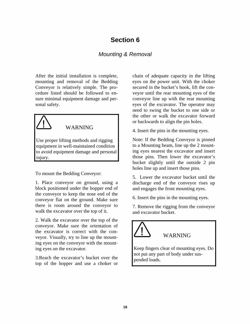
After the initial installation is complete, mounting and removal of the Bedding Conveyor is relatively simple. The pro-cedure listed should be followed to en-sure minimal equipment damage and per-sonal safety.
To mount the Bedding Conveyor:
1. Place conveyor on ground, using a block positioned under the hopper end of the conveyor to keep the nose end of the conveyor flat on the ground. Make sure there is room around the conveyor to walk the excavator over the top of it.
2. Walk the excavator over the top of the conveyor. Make sure the orientation of the excavator is correct with the con-veyor. Visually, try to line up the mount-ing eyes on the conveyor with the mount-ing eyes on the excavator.
3.Reach the excavator’s bucket over the top of the hopper and use a choker or
chain of adequate capacity in the lifting eyes on the power unit. With the choker secured in the bucket’s hook, lift the con-veyor until the rear mounting eyes of the conveyor line up with the rear mounting eyes of the excavator. The operator may need to swing the bucket to one side or the other or walk the excavator forward or backwards to align the pin holes.
4. Insert the pins in the mounting eyes.
Note: If the Bedding Conveyor is pinned to a Mounting beam, line up the 2 mount-ing eyes nearest the excavator and insert those pins. Then lower the excavator’s bucket slightly until the outside 2 pin holes line up and insert those pins.
5. Lower the excavator bucket until the discharge end of the conveyor rises up and engages the front mounting eyes.
6. Insert the pins in the mounting eyes.
7. Remove the rigging from the conveyor and excavator bucket.
WARNING Use proper lifting methods and rigging equipment in well-maintained condition to avoid equipment damage and personal injury.
WARNING Keep fingers clear of mounting eyes. Do not put any part of body under sus-pended loads.

11
Section 7
Troubleshooting
1. Bedding Conveyor does not run:
a. Insufficient oil pressure or flow. Check hydraulic supply system. Correct as re-quired.
b. Material packed in hopper. Inspect and clean if required.
c. Material packed in conveyor frame. In-spect and clean if required.
d. Belt tension too loose. Inspect and ad-just as required. With the belt empty of material; inspect belt tension at the curved portion of the main frame. In this area the belt will bow upwards. Press down on the belt until it contacts the slider bed, estimate the distance traveled. A 2” bow in the belt will be the minimum required to turn the belt. Increase the ten-sion. as required.
e. Skirt board rubber tight against belt. There should be 1/8” to 1/4” clearance between the skirt board rubber and the belt. Adjust as required.
f. Quick couplers not connected. Make sure all quick couplers are fully con-nected.
2. When trying to run the Bedding Con-veyor, the track runs instead of the con-veyor.
a. Check that operating procedures are being followed. Must activate the switch and keep activated for the duration of running the conveyor.
b. Inspect electrical system. Electrical contacts must be kept clean and in good operating condition. Clean contacts and check connections and correct as re-quired.
c. Test electric solenoid coil for continu-ity. Replace as required.
WARNING The Electrical Contact Assembly must be kept clean and maintained in good condition to avoid loss of electrical contact during op-eration resulting in sudden machine move-ment.
With the conveyor running, no material comes out of the hopper.
a. If the bedding material is wet, bridging in the hopper can occur, with sand being the worst for this problem. If wet material is being used, it may become necessary to add a hydraulic vibrator to the side of the hopper. A complete kit, which runs in parallel with the conveyor, can be pur-chased from Felco.
WARNING Lock out excavator to avoid accidental starting of the Bedding Conveyor be-fore any maintenance work is done.

12

13
Section 8
Conveyor and Hydraulic Parts
Conveyor Parts ................................................................................ Page 14 - 21
Hydraulic Parts............................................................................... Pages 22 - 39
Parts listed are all parts for all excavators. Your machine may not have some of the parts shown. Contact Felco’s Technical Service Department for assistance.

14
14
32
56
7
89
10 11
13
14
12

15
MODEL 60 BEDDING CONVEYOR
Mark Quantity Part Number Description
1 1 Main Frame Assembly 2 1 Nose Frame Assembly
3 4 1” x 3-1/4” Hex Head Bolt
4 4 1” Nylock Nut
5 1 Power Unit Assembly
6 1 Motor Cover
7 1 Hopper
8 8 1” x 3-1/4” Hex Head Bolt
9 8 1” Nut and Lockwasher
10 1 Flow Gate
11 2 1” x 2-1/2” Hex Head Bolt
12 2 3 / 4” Flat Washer

16
11
10
98
2
1
34
56
7
12
131
41
5

17
MODEL 60 MAIN FRAME ASSEMBLY
Mark Quantity Part Number Description
1 1 Main Frame 2 1 Conveyor Belt - Laced
3 5 Skirt Board Rubber
4 2 Skirt Board Rubber Retainer Strip
4 2 Skirt Board Rubber Retainer Strip
4 2 Skirt Board Rubber Retainer Strip
4 2 Skirt Board Rubber Retainer Strip
4 2 Skirt Board Rubber Retainer Strip
5 57 3/8” x 1-1/2” Hex Head Bolt
6 57 3/8” Nylock Nut
7 57 3/8” Flat Washer
8 27 Pipe Roller
9 54 Bearing
10 54 Roller Keeper Bracket
11 54 3/8” x 1” Hex Head Bolt and Lock Washer
Optional Belt Service Parts
1 Lace Kit
1 Punch
1 Wrench
1 36” Template

18
1
23
45
76
13
16
15
14
8
91
2
10
11
17
18
20
19

19
MODEL 60 NOSE FRAME ASSEMBLY
Mark Quantity Part Number Description
1 1 Nose Frame 2 2 Take Up Bearing
3 2 1 ¼” B7 All Thread
4 2 1 ¼” Grade 8 Nut
5 2 Taper Lock Bushing with Screws
6 1 Front Pulley Shaft
7 1 5/8” Key
8 1 Front Pulley
9 2 Pipe Roller
10 4 Bearing
11 4 Roller Keeper Bracket
12 4 3/8” x 1” Hex Head Bolt

20
1
54
32
10
11
12
2234
30
31
32
33
27
28
29
23
53
63
9138
37
3433
32
31
30
29
28
27
35
36
6
78
9
15
14
13
17
16
21
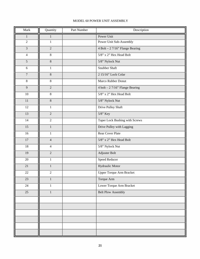
MODEL 60 POWER UNIT ASSEMBLY
Mark Quantity Part Number Description
1 1 Power Unit 2 1 Power Unit Sub-Assembly
3 2 4 Bolt – 2 7/16” Flange Bearing
4 8 5/8” x 2” Hex Head Bolt
5 8 5/8” Nylock Nut
6 1 Snubber Shaft
7 8 2 15/16” Lock Colar
8 8 Marco Rubber Donut
9 2 4 bolt – 2 7/16” Flange Bearing
10 8 5/8” x 2” Hex Head Bolt
11 8 5/8” Nylock Nut
12 1 Drive Pulley Shaft
13 2 5/8” Key
14 2 Taper Lock Bushing with Screws
15 1 Drive Pulley with Lagging
16 1 Rear Cover Plate
17 4 5/8” x 2” Hex Head Bolt
18 4 5/8” Nylock Nut
19 2 Adjuster Bolt
20 1 Speed Reducer
21 1 Hydraulic Motor
22 2 Upper Torque Arm Bracket
23 1 Torque Arm
24 1 Lower Torque Arm Bracket
25 1 Belt Plow Assembly

22
918600

23
HIGH PRESSURE FILTER
Mark Quantity Part Number Description
1 1 O-ring Plug 2 1 105064 Filter Mounting Plate
3 1 918600 Filter Housing Assembly
4 1 918610 Filter Element
5 1 918611 Filter Element O-ring
6
7 1 918597 Complete Filter Assembly

24
XA
B
AP
B
YP
T
YP
TX
AB
T
7
54
1 36
2 8
12
11
10
2 8
12
113
14
57
9
25
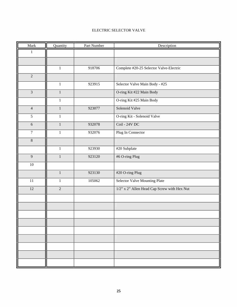
ELECTRIC SELECTOR VALVE
Mark Quantity Part Number Description 1
1 918706 Complete #20-25 Selector Valve-Electric
2
1 923915 Selector Valve Main Body - #25
3 1 O-ring Kit #22 Main Body
1 O-ring Kit #25 Main Body
4 1 923077 Solenoid Valve
5 1 O-ring Kit - Solenoid Valve
6 1 932078 Coil - 24V DC
7 1 932076 Plug In Connector
8
1 923930 #20 Subplate
9 1 923120 #6 O-ring Plug
10
1 923130 #20 O-ring Plug
11 1 105062 Selector Valve Mounting Plate
12 2 1/2” x 2” Allen Head Cap Screw with Hex Nut

26
1
5
6
2
4
3
7
13
14
14
8
9
1712
15
11
10
16
7

27
VIBRATOR HYDRAULIC PLUMBING
Mark Quantity Part Number Description 1 1 918455
918060 918300
Hose Assembly - 48”
2 1 918455 918075 918300
Hose Assembly - 38”
3 1 918455 918075
Hose Assembly - 40”
4 1 918455 918075 918300
Hose Assembly - 20”
5 1 918455 918060
Hose Assembly - 10”
6 1 918455 918060
Hose Assembly - 18”
7 3 916880 Run Tee Adapter
8 1 918521 Check Valve
9 1 916970 Branch Tee Adapter
10 1 916565 O-ring Adapter
11 1 917360 O-ring Adapter
12 1 918690 Flow Control Valve
13 1 916870 Run Tee Adapter
14 2 917310 O-ring Adapter
15 1 917310 O-ring Adapter
16 1 918740 Vibrator Unit
17 1 105066 Mounting Plate
18 2 3/4” x 2-1/2” Bolt with 3/4” Lock Washer

28
12
34
5

29
VIBRATOR UNIT
Mark Quantity Part Number Description 1 1 918750 Hydraulic Motor - Complete
2 1 918770 Hydraulic Motor Seal Kit
3 1 Eccentric Assembly
4 1 918760 Motor Coupling
5 1 918740 Complete Vibrator Unit

30
1 1
2
33
67
76
45
54
8

31
CONTACT RAIL ASSEMBLY
Mark Quantity Part Number Description 1 2 105215 Brass Contact Rail
2
1
105205 105210
Contact Rail Frame
3 2 105220 Insulator Block
4 8 Flat Washer
5 10 Hex Nut
6 4 Hex Head Screw
7 4 Flat Head Screw
8 1 105200 Complete Contact Rail Assembly

32
1
2
3
456
7
8
9
10

33
ROLLER CONTACT ASSEMBLY
Mark Quantity Part Number Description 1 1 105325 Insulator Block
2 1 Nylock Nut
3 2 Roller Mounting Screw
4 2 918990 Brass Contact Wheels
5 6 Plain Hex Nut
6 1 Plain Hex Nut
7 1 Adjustment Stop Screw
8 1 919000 Roller Contact Spring
9
1
105305 105310 105315 105320
Roller Contact Frame
10 1 105300 Complete Roller Contact Assembly

34

35
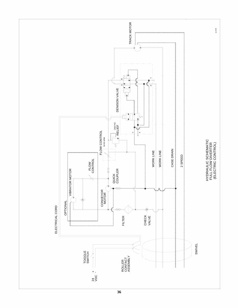
Section 9
Hydraulic Schematics
The schematics shown are for all types of excavators. Contact Felco’s Technical Service Department to determine which schematic is correct for your machine
36
SW
IVE
L
TRA
CK
MO
TOR
-
TOG
GLE
S
WIT
CH
RO
LLE
RC
ON
TAC
TA
SS
EM
BLY
CA
SE
DR
AIN
2 S
PE
ED
WO
RK
LIN
E
WO
RK
LIN
E
CH
EC
KV
ALV
E
24 VD
C+
FULL
FLO
W D
IVE
RTE
R
ELE
CTR
ICA
L C
OR
D
FILT
ER
PT
XY
AB
OP
TIO
NA
L
DE
NIS
ON
VA
LVE
HY
DR
AU
LIC
SC
HE
MA
TIC
VIB
RA
TOR
MO
TOR FL
OW
CO
NTR
OL
CO
NV
EY
OR
MO
TO
R
(ELE
CTR
IC C
ON
TRO
L)
QU
ICK
CO
UP
LER
FLO
W C
ON
TRO
L
RE
LIE
F
50-5
5 G
PM
2500
PS
I
Q-2
97E

37
CO
NN
EC
T T
O P
INS
NO
& C
RE
G
IN BY-PASS