Embed Size (px)
Citation preview
Technische Änderungen vorbehalten.
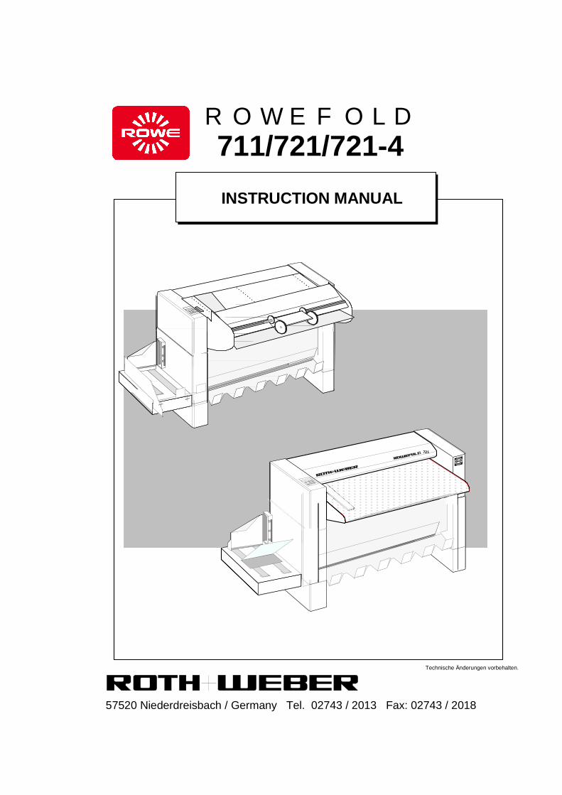
INSTRUCTION MANUAL
721
57520 Niederdreisbach / Germany Tel. 02743 / 2013 Fax: 02743 / 2018
711/721/721-4
ROWEFOLD
Instruction manual Rowe 721-4 01/16
2
Table of contents .......................................... page 1.0 SAFETY INSTRUCTION ......................... 3 2.0 TECHNICAL DATA ................................ 7 3.0 SET UP A. ASSEMBLING ..................... 8 3.1 Set up .................................................... 8 3.2 Connection of machine .......................... 8 4.0 INTRODUCTION ................................... 9 4.1 Switching on .......................................... 9 4.2 Switching off .......................................... 9 5.0 OPERATING ELEMENTS .................... 10 5.1 Standardized settings ............................. 10 5.2 Programmes for length folding ............... 10 5.3 Programmes for cross folding ................. 11 5.4 Set back error report ............................... 11 6.0 FOLDING PROCESS ............................ 12 6.1 Length folding ......................................... 12 6.2 Front run out ........................................... 13 6.3 Cross folding ........................................... 14 6.4 Collection magazine ............................... 14 6.5 Tape applicator ....................................... 15 6.6 Sorter ...................................................... 17 7.0 TROUBLE SHOOTING .......................... 20 7.1 Paper jam in feed section ..................... 21 7.2 Opening rear side ................................... 22 7.3 Error report for paper guiding grid .......... 22 7.4 Paper jam in cross folding section .......... 23 7.5 Malfunction chart .................................... 24 Wiring diagram Spare parts list

Instruction manual Rowe 721-4 01/16
3
1.0 SAFETY INSTRUCTIONS This instruction manual contains satety remarks in all relevant sections, as well as warnings
related to possible danger. For this purposes, these symbols are being used:
i
Important shows application tips and other important information. Caution Indicates immediate threat or danger.
i
Before mounting and commissioning read the Instruction Manual and safety instructions and conform to then.
Make sure that each operator reads the manual and keep it always available near the machine.
Do not remove any screwed-on parts. Make sure that no foreign matters enter into the machine !
Before carrying out any work on the electrical or mechanical part of the machine, separate the system from the main voltage !
Withdraw power supply cord !
Ensure that you have easy and save access for the power supply cord !
Never bridge safety switch !
First check that main voltage corresponds with voltage indicated on type label !
The connection must only be done via a protected contact plug, matching the cutoff condition, according to VDE (VDE=Electrical Regulatory Authority) 0100 section 410, so that protection against electrical stroke is ensured !
1.1 Safety Data Sheets Exclusion of responsibility: The following exclusion of responsibility applies to all Safety Data Sheets of the Instruction Manual. This Safety Data Sheet has been written to the best of our knowledge and serves as compact instruction for the safe operation of this product. We reserve the right to update Safety Data Sheets if new information is available. It is up to the customer to assess the suitability of such information for complying with safety measures. In case of doubt, the user should contact the producer in order to be sure that he got the latest edition of the Safety Data Sheet. Should any limitation to resposibility be allowed according to ruling law, we do not assume any responsibility for any inaccuracies in this documentation. 1.2 General Remarks Any warranty work must done by us, on principle, or by a dealer authorized by us. Have maintenance or repair work done by the appropriate service.

Instruction manual Rowe 721-4 01/16
4
1.3 Saftey Data Sheet - ROWEFOLD 721-4
Type ROWEFOLD 721-4 Manufacturer Roth + Weber Maschinenfabrik GmbH 57520 Niederdreisbach Germany Discription Folding machine for the processing of copying material Folding Speed 18 m/min Dimensions Width: 1760 mm Depth: 1100 mm Height: 1000 mm Weight 225 kg Tension 220 - 240 V Frequency 50 - 60 Hz Nominal current 1,5 A Connected load 350 VA Mains connection Power supply cord with earthed plug Sound level 58 dB(A) when working, at operator position Space volume Recommendation 50 m3 Fresh air intake Recommendation 30m3/h - natural fresh air feed Room temperature Recommendation 10°C - 35°C Relative air humidity Recommendation 15% - 85% Folding volume approx. 500m2, over 8 hours Foldable Materials Copy normal paper 60 - 110 g/m2 Coloured paper 80 g/m2 Plotter normal paper 60 - 110 g/m2 Electrostatical material 80 g/m2 Diazo paper 60 - 110 g/m2 Format size Length (Length folding) 390 bis 6000 mm Length (Cross folding) 390 bis 2500 mm Width 960 mm Package width during CF 230 mm Directive CE 73 / 23 / EWG ( 93 / 68 / EWG ) CE 89 / 336 / EWG
Notes Instruction Manual and Safety Instructions must be adhered to.
Exclusion of warranty applies to the contents of this Safety Datd Sheet.

Instruction manual Rowe 721-4 01/16
5
1.4 Intended use of ROWEFOLD 721-4 The intended use of the ROWEFOLD 721-4 is to fold copying paper. Any different use, beyond the application purposes mentioned herein, are not as directed. With this folding machine plans are length and cross folded according to DIN-Standard. Intended use means also: - Adhering to Instruction Manual. - Complying with Safety Instructions. - Check that local main voltage corresponds with voltage indicated on type label.
Any arbitrary conversions and modifications are not allowed and will release the manufacturer from any responsibility and liability for any damages arising from such measurements. Safety means, casings, covers etc. should not be removed or made ineffective.
We reserve the right to technical modifications when serving safety and improvement. Roth + Weber expressly reserves the right to technical modifications and further development. Roth + Weber has no obligation to retro-fitting of technical modifications on machines already installed. 1.5 Qualification of operating personnel of the ROWEFOLD 721-4 For all work with or on the machine the Safety Instructions and remarks contained in the Instruction Manual must be adhered to. The operating personnel has an obligation: - To abstain from all working mode which could jeopardize the safety and functional performance of the ROWEFOLD 721-4. - To make sure that only trained and authorized personnel will be working with the ROWEFOLD 721-4. - To state any changes which could jeopardize the safety and functional performance of the ROWEFOLD 721-4. - Before carrying out any maintenance and repair work on the ROWEFOLD 721-4, separate the system from the main voltage.

Instruction manual Rowe 721-4 01/16
6
1.6 Possible danger sources of the ROWEFOLD 721-4
In general, the ROWEFOLD 710 has to be disconnected from the power supply before interventing !
An intervention at the machine can be carried out at the following mentioned points: - Side door on the left When touching the electrical supply, there is the danger of a current impact. - Side door on the right When touching the wiring, there is the danger of a current impact. When interventing in the gear-tooth system, there is also the danger of injuring. - Covering sheet metal at the front (under the conveyor table) When interventing in the gear-tooth system of the folding roller and within the gap between folding roller and paper guide plate, there is the danger of injuring. - Covering sheet metal at the front (under conveyor table) When interventing the gear-tooth system of the folding roller and within the gap between folding roller and paper guide plate, there is the danger of injuring. When interventing the tape transport and the cutting area of the tape applicator there is the danger of injuring. When interventing the gear-tooth system of the feed-in table there is the danger of injuring. When interventing the feed table switch system there is the danger of injuring 1.7 Recycling and disposal The total weight of ROWEFOLD 721-4 amounts to 225 kg. This is allotted to approx.: 202 kg steel and stainless steel 10 kg stepping motors and transformers 8 kg plastic and rubber 5 kg electronical parts When reaching the end of the life time of ROWEFOLD, it must be disposed, according to the regulations of waste disposal applying at that point in time.
Instruction manual Rowe 721-4 01/16
7
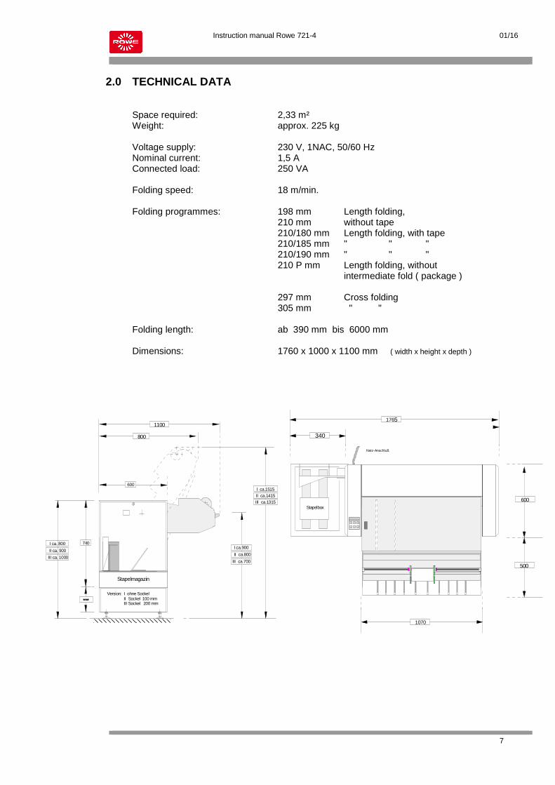
2.0 TECHNICAL DATA Space required: 2,33 m² Weight: approx. 225 kg Voltage supply: 230 V, 1NAC, 50/60 Hz Nominal current: 1,5 A Connected load: 250 VA Folding speed: 18 m/min. Folding programmes: 198 mm Length folding, 210 mm without tape 210/180 mm Length folding, with tape 210/185 mm " " " 210/190 mm " " " 210 P mm Length folding, without intermediate fold ( package ) 297 mm Cross folding 305 mm " " Folding length: ab 390 mm bis 6000 mm Dimensions: 1760 x 1000 x 1100 mm ( width x height x depth )
740
III ca. 1000
***
Stapelmagazin
II ca.1415
1100
600
800
Netz-Anschluß
600
500
1070
340
Stapelbox
1765
I ca. 800
II ca. 900
Version: I ohne Sockel II Sockel 100 mm III Sockel 200 mm
I ca.1515
III ca.1315
III ca.700
II ca.800
I ca.900

Instruction manual Rowe 721-4 01/16
8
3.0 SET UP AND ASSEMBLING 3.1 Set-up The delivery of the folding machine will be fully assembled. Place folding machine horizontally on safe ground. Keep a minimum distance of 0.4 meters between wall and back side of machine. An exact setting can be achieved with the help of the placing feet. The steel balls will be put in the holding parts in the feed in section of the folding machine.
3.2 Connection of machine Before connecting machine to the power supply, the machine must be completely mounted. The connection must only be done via a protected contact plug, matching the cutoff condition, according to VDE (VDE=Electrical Regulatory Authority) 0100 section 410, so that protection against electrical stroke is ensured.
Check whether power supply corresponds with voltage stated on the type plate beforehand !
Netz-Anschluß
Stapelbox
0,3 m
min. 0,4 m
0,3 m

Instruction manual Rowe 721-4 01/16
9
4.0 Introduction 4.1 Switching on Set mains switch at the rear side of machine to position " I " .
After switching on, the folding programme 210* will be activated and displayed. Now, the machine is ready for operation, the required programme may be selected. * The folding programme can be choosen in advance by the service technician in order to meet specific customer requirements. 4.2 Switching off Set main switch to position " 0 ".
0
I
main switch

Instruction manual Rowe 721-4 01/16
10
5.0 OPERATIONAL ELEMENTS 5.1 Standard setting After turning on the mains switch, the folding programme 210 will be activated. 5.2 Length folding programmes By pushing the corresponding keys, the following programmes may be selected:
198 mm folding package with creation of an intermediate fold. 210 mm folding package with creation of an intermediate fold. Display The selected folding programme will be displayed. Those folding programmes with different margins can be selected by repeatedly pushing the corresponding keys. 210/180 folding package with creation of an intermediate fold. folding package = 180 mm mit 30 mm margin. 210/185 folding package = 185 mm mit 25 mm margin. 210/190 folding package = 190 mm mit 20 mm margin.
297 / 305
210 / 190210 198
Paket / 210
297
305
Display
Wahltaster für Längsfaltungen
Stop-Taster
Wahltaster für Querfaltungen
198
210
210/190

Instruction manual Rowe 721-4 01/16
11
5.0 OPERATION ELEMENTS 5.2 Length folding programmes
Push key for package folding. 210 P mm folding package without creation of an intermediate fold.
On the right hand side, P will be displayed in addition. Only full folds will be made. From a remaining length of about 80 mm, plans will be folded at the pitch edge. With a remaining length shorter than 80 mm, the last sheet will be centrically folded.
5.3 Cross folding programmes
Only packages with a maximum width of 230 mm can be cross folded. A sensor located in the lower folding section will monitor the allowable package width. Keep pushing keys until the requested programmes will be displayed. 297 oder 305 mm package length. Push key once or twice. On the left hand side, an upper or lower reading will be displayed. (for example 297) By pushing the STOP-key the complete drive may be stopped. J08 will be displayed. Unevenly fed plans can be drawn back during the phase of stand-still. When larger break downs occur, please refer to page 18 - 21. 5.4 Set back of error report
The stoppage phase and error reports may only be lifted by pushing the key P-210. Keep switch turned off for about 2-3 seconds.
Paket 210
297 / 305
Paket 210

Instruction manual Rowe 721-4 01/16
12
6.0 FOLDING PROCESS 6.1 Length folding
Select requested folding programme for example 210 with cross folding programme 297.
display
Manual feed in: Put plan against lineal with printed side down ( Pos. A ) and title block at front. The drive will be automatically activated. Push plan into the machine until it will be taken hold of and drawn in by the rollers.
i
Longer plans must be manually led at the lineal when being drawn in. Plans must not run into the machine beyond the red markins. The markin gives an information about the working area. To avoid false foldings no new plans may be fed during the folding process. For exact folding, plans must be cut rectangularly.
After folding, the folded material will run into the lateral stacking device and the drive stopps.
210 297 / 305
Handanlage
B
AC
Online
Instruction manual Rowe 721-4 01/16
13
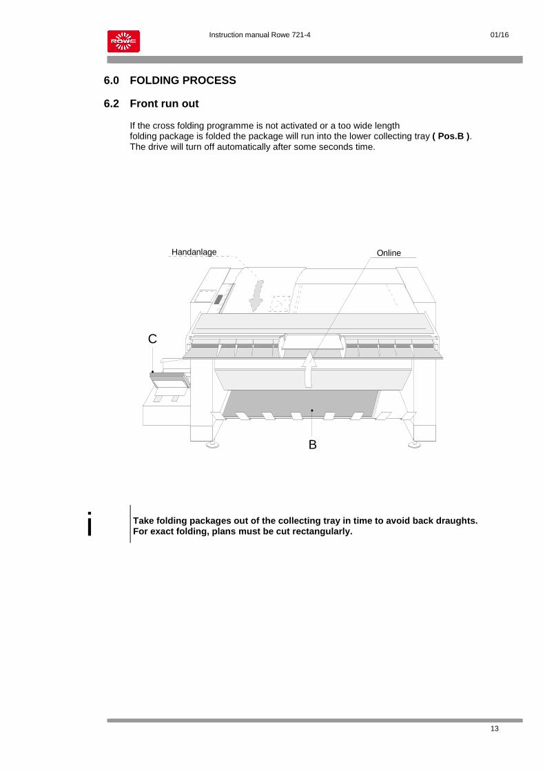
6.0 FOLDING PROCESS 6.2 Front run out If the cross folding programme is not activated or a too wide length folding package is folded the package will run into the lower collecting tray ( Pos.B ). The drive will turn off automatically after some seconds time.
i
Take folding packages out of the collecting tray in time to avoid back draughts. For exact folding, plans must be cut rectangularly.
Handanlage
B
AC
Online
Instruction manual Rowe 721-4 01/16
14
6.0 FOLDING PROCESS
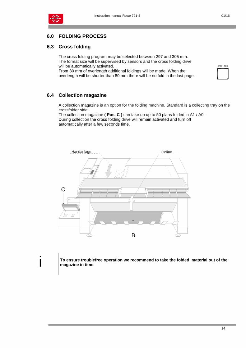
6.3 Cross folding The cross folding program may be selected between 297 and 305 mm. The format size will be supervised by sensors and the cross folding drive will be automatically activated. From 80 mm of overlength additional foldings will be made. When the overlength will be shorter than 80 mm there will be no fold in the last page. 6.4 Collection magazine A collection magazine is an option for the folding machine. Standard is a collecting tray on the crossfolder side. The collection magazine ( Pos. C ) can take up up to 50 plans folded in A1 / A0. During collection the cross folding drive will remain activated and turn off automatically after a few seconds time.
i
To ensure troublefree operation we recommend to take the folded material out of the magazine in time.
297 / 305
Handanlage
B
AC
Online
Instruction manual Rowe 721-4 01/16
15
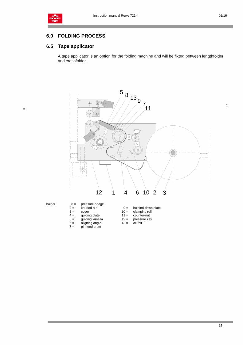
6.0 FOLDING PROCESS 6.5 Tape applicator A tape applicator is an option for the folding machine and will be fixted between lengthfolder and crossfolder.
1
=
holder 8 = pressure bridge 2 = knurled-nut 9 = holdind-down plate 3 = cover 10 = clamping roll 4 = guiding plate 11 = counter-nut 5 = guiding lamella 12 = pressure key 6 = aligning angle 13 = oil-felt 7 = pin feed drum
1 2 34
5
6
7
89
10
11
12
13
Instruction manual Rowe 721-4 01/16
16
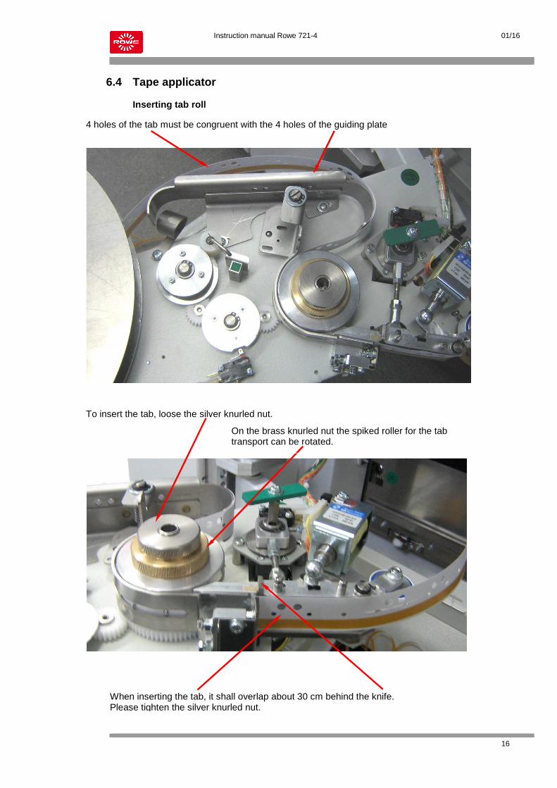
6.4 Tape applicator Inserting tab roll
4 holes of the tab must be congruent with the 4 holes of the guiding plate
To insert the tab, loose the silver knurled nut.
When inserting the tab, it shall overlap about 30 cm behind the knife. Please tighten the silver knurled nut.
On the brass knurled nut the spiked roller for the tab transport can be rotated.
Instruction manual Rowe 721-4 01/16
17
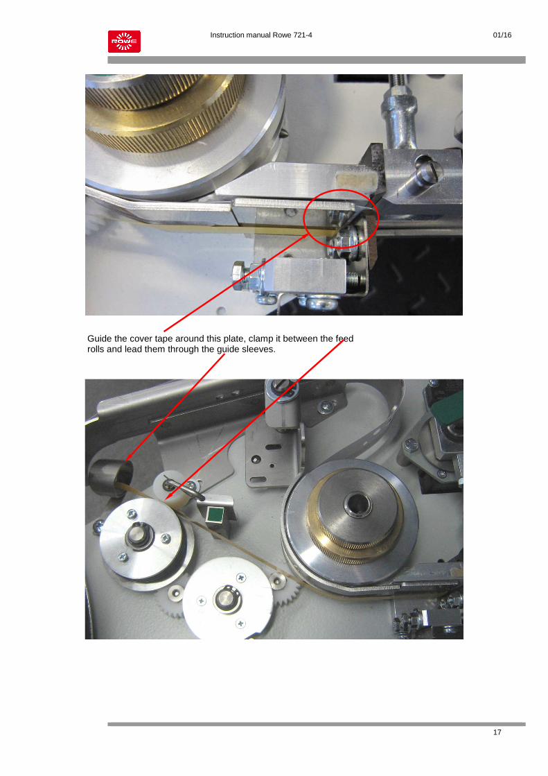
Guide the cover tape around this plate, clamp it between the feed rolls and lead them through the guide sleeves.

Instruction manual Rowe 721-4 01/16
18
Install the tab guide as shown. Check if the knurled nut is fastened correct.
After the tab change, put 1-2 drops of oil on this felt.
After inserting the tab and the cover tape, the tab can be cut when rotating the handle counterclockwise.

Instruction manual Rowe 721-4 01/16
19
6.6 Sorter A sorter is an option for the folding machine and is placed instead of the collection magazine next to the cross folder. Connection: The sorter is located at the left hand side case of the folder. Fixation is being done by means of a bottom plate with two running rails, fixed to the rail system of the folder. By means of a locking device ( A ), the sorter is latched to the side case. When the sorter is driven back, the power supply will automatically be interrupted.
i
The bottom plate for collection of the sorter must be aligned exactly towards the side case, in order to enable troublefree locking of the sorter. For this purpose, the spacer will be supplied separately.
225
ca.3
1019
20
A
trav
ellin
gso
rter
814.5
ca.5
0
1325
1065.5
814.5
Sorter
A
500
ROWE 721-4
600
ca.1
280
1070
1010
740
ca.7
90
670-
780m
m
ca. 1
310

Instruction manual Rowe 721-4 01/16
20
6.6 Sorter
B5
B5
M4
M5
B4
M4
B4
B3
B2
B1
M1
M3
M5
M7
M2
M6
Tray 1
Tray 2
Tray 3
handle sorter door
sorter door
transport Belts green
locking device sorter

Instruction manual Rowe 721-4 01/16
21
6.6 Sorter Function:
The cross-folded package will be transported by the cross folder of the folding machine into the sorter's pressure rocker. Sensor B5 will be activated and the rocker will be moved by means of motor M4 / sensor B4 towards the transport belts. Motor M5 will start up and the plan will be transported upwards inbetween the belts and the rollers. The rollers will be driven by a toothed belt inside the right hand side case.
After a short time of pressurizing, the pressure rocker will go back to its starting position, waiting for the next plan to arrive. The stream feeder I will be filled first of all. The display stream feeder I FULL will be done by sensor B1, the sensor will remain covered and the sorter control will recognize the stacker to be filled. Automatically, shunt I will be opened for the next plan to come in and plans to follow will now
be stacked in stream feeder II. The message stream feeder II FULL will be initiated by sensor B2. When using the third stream feeder (option), plans will be being stacked, according to the same procedure. As soon as all stream feeders are filled (sensors B1 - B3 covered), a corresponding message will be given to the operator via the software. For removing a paper jam, the sorter may be pull off from the side case of the folding machine. The cross folding section of the folding machine is now freely accessible. By opening the rear door, the transport section will be opened, by removing the lower cover the drive motors M4 and M5 will be accessible. Inside the left hand side case the electronical components are located. The upper cover plate will be removed by loosening of the screws ( B ). If, despite having dislocked the sorter at the side case (plug), no voltage should be there, the fuse (5A sluggish) might be defective.
i
Only plans with a cross folding width from 297 - 305 mm can be processed. The maximum cross folding length which can be processed is 2500mm. During the folding / transporting procedure, the rear door at the sorter must not be opened. That door is provided with a safety switch and will interrupt the power supply of the sorter when being opened.
Instruction manual Rowe 721-4 01/16
22
7.0 TROUBLE SHOOTING
In general, the machine has to be disconnected from the power supply before interventing !
Remove mains plug !
Never ever remove plug from the machine to switch machine off but always set mains switch to position 0 first !
Never ever shortcut safety switches, because a safe working is not possible ! Possible faults which may occur during transport or the folding process may be easily solved by openening the individual machine parts. Set machine to stop first and then set mains switch to position "0". Most of the time, the plans can still be drawn back. If this should not be possible the individual covers may be easily opened with snap buckles.
i
Diazo material in semi-dry process, copying material in zincoxyde process or with wet development may only be processed in dry condition in this folding machine.
Plotting material partly shows considerable bends. Before folding, the pitch edge has to be manually flattened.
To ensure an exact folding process, plans must be free of statical charging.

Instruction manual Rowe 721-4 01/16
23
7.0 TROUBLE SHOOTING 7.1 Paper jam in feed section Open upper cover. This cover may be moved to the front or the rear side. To do so, push the corresponding locking bars inside ( A - B rear side ).
i
A safety switch is mounted in the left sidebox; it switches off the folder when the covering is open. When closing the covering, maintain a watch to ensure the correct engaging of the bolts, as, otherwise, no proper function will be possible.
Open front feed blade with turn-lock fastener C and take it out.
The upper transport roller may be moved to the rear side ( D ). Remove rest of paper entirely, re-implant parts and shut cover.
A
A
C C
D D
Instruction manual Rowe 721-4 01/16
24
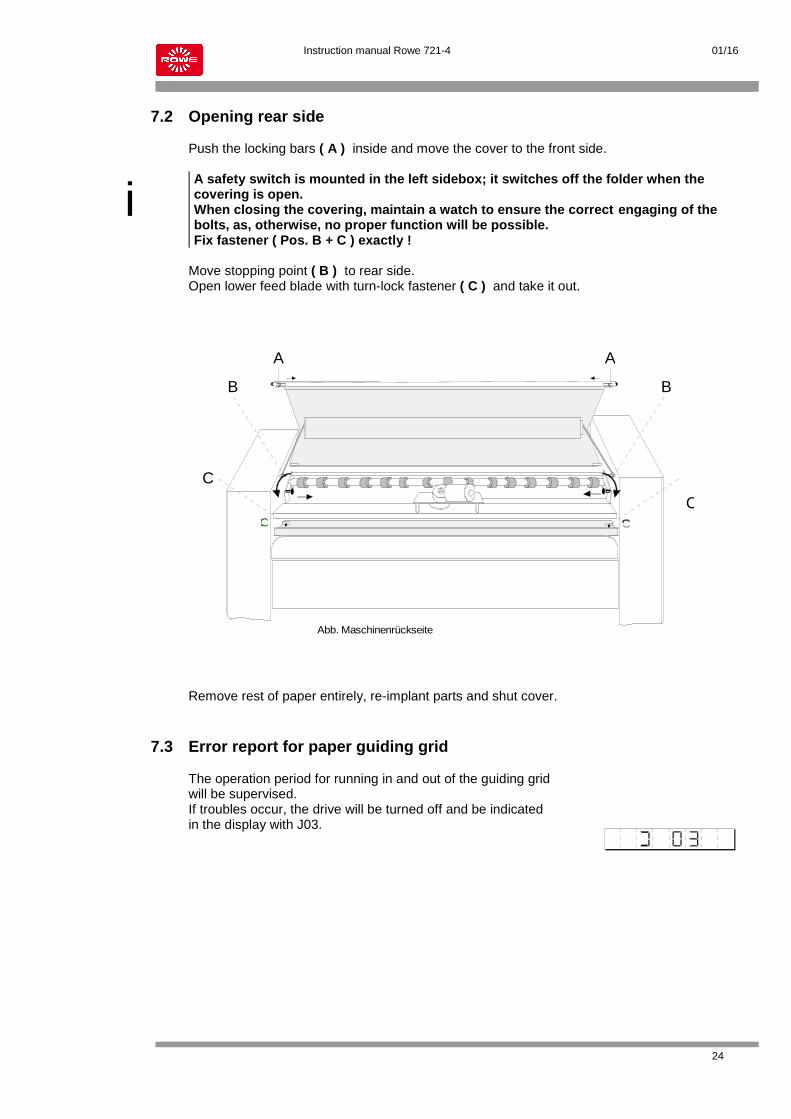
7.2 Opening rear side Push the locking bars ( A ) inside and move the cover to the front side.
i
A safety switch is mounted in the left sidebox; it switches off the folder when the covering is open. When closing the covering, maintain a watch to ensure the correct engaging of the bolts, as, otherwise, no proper function will be possible. Fix fastener ( Pos. B + C ) exactly !
Move stopping point ( B ) to rear side. Open lower feed blade with turn-lock fastener ( C ) and take it out. Remove rest of paper entirely, re-implant parts and shut cover. 7.3 Error report for paper guiding grid The operation period for running in and out of the guiding grid will be supervised. If troubles occur, the drive will be turned off and be indicated in the display with J03.
A
C
B
A
C
B
Abb. Maschinenrückseite

Instruction manual Rowe 721-4 01/16
25
Jam recognition and removal
Rowe 721-1 / 721-4
Possible jam areas
By driving away the folding machine from the printer or opening a cover, a safety circuit comes into
force which switch offs the machine.
After removing a jam all covers or units need to be place in the original position to ensure the functionality.
J06 J04
J00 J03 J04J06
J05
J00 J01J05

Instruction manual Rowe 721-4 01/16
26
Jam display J00 J03 J04 J06
1. To check and remove the jams J00, J03, J06, swing the manual feeding table on the handle piece upwards and secure it by using the corresponding holder.
2. Slide both unlocking devices in the direction of the arrows to open the upper cover.
Handle piece
Holder
Upper cover Locking and unlocking of upper cover. When closing the cover, care must be taken that the latch bolt is snapped correctly.
Picture 1
Picture 2
Picture 3
Lever assembled until production year 2008

Instruction manual Rowe 721-4 01/16
27
3. By raising the green shaft, the transport roll will be relieved and to ensure the removal of the occurred paper jam. 4. After the jam removal put the green lever until production year 2008 (see red circle) back into position 1.
Jam display J00 J01 J05
5. To check and remove the jams J00, J01, J05, the carry-over table can be swung up by using the unlocking lever.
Position 1 normal position
Position 2 relax position
Unlocking lever Carry-over table
Picture 4
Picture 5
Picture 6
Reset button for jamJ03

Instruction manual Rowe 721-4 01/16
28
6. When opening the lower covering and shifting out of the tab applicator, the lower transport area is accessible.
Tilted carry-over table
Lower covering
Tab applicator
Swing up of the upper deflection on this shaft Position 2 After jam removal put the shaft again in position 1- see picture 11
Picture 7
Picture 8
Picture 9
When opening the jam door the horizontal transport is accessible – see picture 12

Instruction manual Rowe 721-4 01/16
29
Picture 10 Picture 11
Position 2
Position 1
Picture 12
Open jam door

Instruction manual Rowe 721-4 01/16
30
7.4 Paper jam in cross folding section
For access to the cross folding area, open the side door on this locking
Picture 13
After removal of the side door pull out the conveyor system
Picture 13
Picture 14
Corssfolder
When unscrewing of the nuts A+B and lifting both guiding covers can be removed.
A B Guiding covers to be lifted here
Instruction manual Rowe 721-4 01/16
31
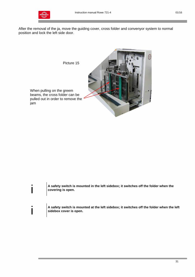
After the removal of the ja, move the guiding cover, cross folder and convenyor system to normal position and lock the left side door.
i
A safety switch is mounted in the left sidebox; it switches off the folder when the covering is open.
i
A safety switch is mounted at the left sidebox; it switches off the folder when the left sidebox cover is open.
Picture 15
When pulling on the greem beams, the cross folder can be pulled out in order to remove the jam

Instruction manual Rowe 721-4 01/16
32
7.5 Malfunction chart In case of one of the following mentioned distribances of the service program, the operation will be interrupted immediately and will be shown in the display:
Code Funktion / Error Solution
J 00 Malfunction-Sensors Sensor B1, B0 or B6 have been covered.
Check possible paper rests
J 01 Malfunction-Tape applicator (ROWE 721, 721-4) Sensor B18 will not be reached by the plan.
Check tape applicator
J 03 Malfunction-Motor M3
Motor M3 for grid doses not reach the final position in time or at all.
Check over-current trigger F5
J 04 Malfunction-Paper transport Sensor B6 will not be reached by the plan.
Transport rollers do not lay on correctly.
J 05 Malfunction-Crossfolder (ROWE 721, 721-4) Paper jam in cross fold section
Cancel error message.
J 06
Malfunction-Paper transport (Rowe 721-4) Sensor B3 will not be reached by the plan.
J 07 Malfunction-Manual feed in (ROWE 721-4) During online conveyance a paper is conveyed manua
Conveyor table sensor B9
J 08
The STOP-buttom will be activated.
J09 Sorter full (Rowe 721-4) Sensors of stacker levels covered.
Cover levels empty.
J10 Stacker level 1 full (Rowe 721-4) Sensor of stacker level covered.
Stacker level empty.
J11 Stacker level 2 full (Rowe 721-4) Sensor of stacker level covered.
Stacker level empty.
J12 Stacker level 3 full (Rowe 721-4) Sensor of stacker level covered.
Stacker level empty.
J13 Jam pressure rocker (Rowe 721-4) Sensor of pressure rocker covered.
Open rear side cover door, remove jam.