Embed Size (px)
Citation preview
warning Read rules for safe operation and instructions carefully. ECHO provides an Opera-tor's Manual and a Safety Manual. Both must be read and understood for proper and safe operation.
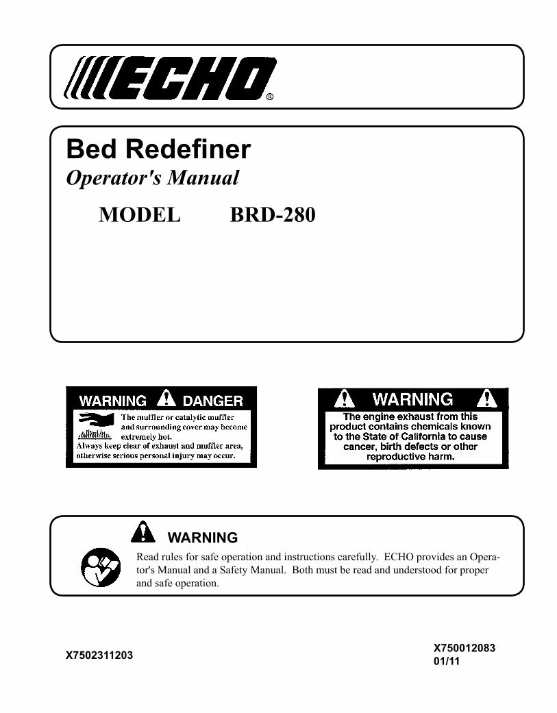
Bed RedefinerOperator's Manual
MODEL BRD-280
X75001208301/11X7502311203
2
Copyright© 2011 By Echo, IncorporatedAll Rights Reserved.
IntroductIon
Welcome to the ECHO family. This ECHO product was designed and manufactured to provide long life and on-the-job-dependability. Read and understand this manual and the SAFETY MANUAL you found in the same package. You will find both easy to use and full of helpful operations tips and SAFETY messages.
table of contentsIntroduction ................................................................2 - The Operator's Manual ........................................2 - The Safety Manual ..............................................2Safety .........................................................................3 - Manual Safety Symbols and Important Information ..........................................................3 - International Symbols .........................................3 - Personal Condition and Safety Equipment .........4 - Equipment ...........................................................6 Emission Control .......................................................6Description .................................................................7Contents .....................................................................9Assembly....................................................................9 - Drive Shaft/Power Head .....................................9 - Throttle Linkage and Ignition Leads .................10 - Support Handle ................................................. 11 - Edger Blade Installation .................................... 11Operation ..................................................................12 - Fuel ....................................................................12 - Starting Cold Engine .........................................14 - Starting Warm Engine .......................................15 - Stopping Engine ................................................16 - Operating Techniques ........................................16 - Edging Operation ..............................................17
Maintenance .............................................................19 - Skill Levels ........................................................19 - Maintenance Intervals .......................................19 - Air Filter ............................................................20 - Fuel Filter ..........................................................20 - Spark Plug .........................................................21 - Cooling System .................................................21 - Exhaust System .................................................22 - Carburetor Adjustment .....................................23 - High Altitude Operation .................................23 - Drive Shaft Lubrication .....................................24 - Blade Replacement / Lubrication ......................25Troubleshooting .......................................................27Storage .....................................................................28Specifications ...........................................................29Warranty Statements ................................................30Servicing Information ..............................................36 - Parts/Serial Number ..........................................36 - Service ...............................................................36 - ECHO Consumer Product Support ...................36 - Warranty Card ...................................................36 - Additional or Replacement Manuals .................36
Specifications, descriptions and illustrative material in this literature are as accurate as known at the time of pub-lication, but are subject to change without notice. Illustra-tions may include optional equipment and accessories, and may not include all standard equipment.
the operator's manual Read and understand this manual before operation. Keep it in a safe place for future reference. Contains specifications and information for operation, starting, stopping, maintenance, storage, and assembly specific to this product.
the safety manual Read and understand this manual before operation. Keep it in a safe place for future reference. Explains possible hazards involved with the use of Bed Redefiners and the measures you should take to make their use safer.
Bed RedefineROpeRatOR's Manual 3
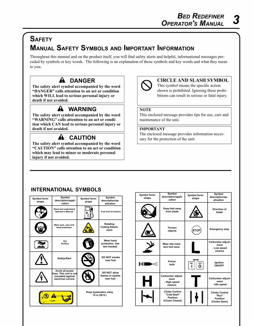
safetymanual safety symbols and Important InformatIonThroughout this manual and on the product itself, you will find safety alerts and helpful, informational messages pre-ceded by symbols or key words. The following is an explanation of those symbols and key words and what they mean to you.
InternatIonal symbols
Hot Surface
Symbol description/appli-
cation
Symbol form/shape
Symbol description/ap-
plication
Symbol form/shape
Read and understand Operator's Manual.
Wear eyes, ears and head protection
Fuel and oil mixture
Safety/Alert
Avoid all power lines. This unit is not
insulated against electrical current.
Wear hand protection. Use
two handed.
DO NOT smoke near fuel.
DO NOT allow flames or sparks
near fuel.
Keep bystanders away15 m (50 ft.)
Symbol description/appli-
cation
Symbol form/shape
Symbol description/ap-
plication
Symbol form/shape
Carburetor adjust-ment
- Idle speed
Carburetor adjust-ment
- High speed mixture
Emergency stop
Carburetor adjust-ment
- Low speed mixture
Wear slip resis-tant foot wear.
IgnitionOn/OFF
Primer bulb
Keep feet awayfrom blade
Thrownobjects
Direction ofblade
Choke Control "Cold Start"
Position (Choke Closed)
Choke Control "Run"
Position (Choke Open)
warningThe safety alert symbol accompanied by the word “WARNING” calls attention to an act or condi-tion which CAN lead to serious personal injury or death if not avoided.
CIRCLE AND sLAsh syMBOLThis symbol means the specific action shown is prohibited. Ignoring these prohi-bitions can result in serious or fatal injury.
CAUTIONThe safety alert symbol accompanied by the word “CAUTION” calls attention to an act or condition which may lead to minor or moderate personal injury if not avoided.
NOTEThis enclosed message provides tips for use, care and maintenance of the unit.
IMPORTANTThe enclosed message provides information neces-sary for the protection of the unit.
DangErThe safety alert symbol accompanied by the word “DANGER” calls attention to an act or condition which WILL lead to serious personal injury or death if not avoided.
RotatingCutting Attach-
ment
4
Physical ConditionYour judgment and physical dexterity may not be good: • if you are tired or sick, • if you are taking medication, • if you have taken alcohol or drugs.Operate unit only if you are physically and mentally well.
Eye ProtectionWear eye protection that meets ANSI Z87.1 or CE require-ments whenever you operate the unit.
Hand ProtectionWear no-slip, heavy duty work gloves to improve your grip on the edger handles. Gloves also reduce the transmission of machine vibration to your hands.
Hearing ProtectionECHO recommends wearing hearing protection whenever unit is used.
Vibration and Cold It is believed that a condition called Raynaud’s Phenomenon, which affects the fingers of certain individuals, may be brought about by exposure to vibration and cold. Exposure to vibration and cold may cause tingling and burning sensa-tions, followed by loss of color and numbness in the fingers. The following precautions are strongly recommended, because the minimum exposure which might trigger the ailment is unknown.
• Keep your body warm, especially the head, neck, feet, ankles, hands, and wrists.
• Maintain good blood circulation by performing vigorous arm exercises during frequent work breaks, and also by not smoking.
• Limit the hours of operation. Try to fill each day with jobs where operating the edger or other hand-held power equipment is not required.
• If you experience discomfort, redness, and swelling of the fingers, followed by whitening and loss of feeling, consult your physician before further exposing yourself to cold and vibration.
personal condItIon and safety equIpment
warningBed Redefiner users risk injury to themselves and others if the Bed Redefiner is used improperly and or safety pre-cautions are not followed. Proper clothing and safety gear must be worn when operating an Bed Redefiner.
Proper Clothing Wear snug fitting, durable clothing;• Pants should have long legs, shirts with long sleeves.• DO NOT WEAR SHORTS,• DO NOT WEAR TIES, SCARVES, JEWELRY,
or clothing with loose or hanging items that could become entangled in moving parts or surrounding growth..
Wear sturdy work shoes with nonskid soles;• DO NOT WEAR OPEN TOED SHOES,• DO NOT OPERATE UNIT BAREFOOTED.Wear no-slip, heavy duty work gloves.Keep long hair away from engine and air intake. Retain hair with cap or net.
Hot Humid WeatherHeavy protective clothing can increase operator fatigue which may lead to heat stroke. Schedule heavy work for early morning or late afternoon hours when temperatures are cooler.
warning The ignition components of this machine generate an electromagnetic field during operation which may interfere with some pacemakers. To reduce the risk of serious or fatal injury, persons with pacemakers should consult with their physician and the pacemaker manufacturer before operating this machine. In the absence of such informa-tion, ECHO does not recommend the use of ECHO products by anyone who has a pacemaker.
Bed RedefineROpeRatOR's Manual 5
warningDo not operate this product indoors or in inadequately ventilated areas. Engine exhaust contains poisonous emissions and can cause serious injury or death.
Read the Manuals• Provide all users of this equipment with the Operator’s Manual and
Safety Manual for instructions on Safe Operation.
Clear the Work Area• Spectators and fellow workers must be warned, and children and
animals prevented from coming nearer than 15 m (50 ft.) while the unit is in use.
Keep a Firm Grip• Hold the front and rear handles with both hands, with thumbs and
fingers encircling the handles.
Keep a solid stance• Maintain footing and balance at all times. Do not stand on slippery,
uneven or unstable surfaces. Do not work in odd positions or on lad-ders. Do not over reach.
Avoid hot surfaces• Keep exhaust area clear of flammable debris. Avoid contact during
and immediately after operation.
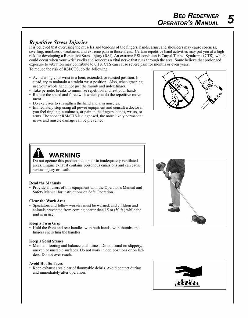
Repetitive Stress Injuries It is believed that overusing the muscles and tendons of the fingers, hands, arms, and shoulders may cause soreness, swelling, numbness, weakness, and extreme pain in those areas. Certain repetitive hand activities may put you at a high risk for developing a Repetitive Stress Injury (RSI). An extreme RSI condition is Carpal Tunnel Syndrome (CTS), which could occur when your wrist swells and squeezes a vital nerve that runs through the area. Some believe that prolonged exposure to vibration may contribute to CTS. CTS can cause severe pain for months or even years. To reduce the risk of RSI/CTS, do the following:
• Avoid using your wrist in a bent, extended, or twisted position. In-stead, try to maintain a straight wrist position. Also, when grasping, use your whole hand, not just the thumb and index finger.
• Take periodic breaks to minimize repetition and rest your hands. • Reduce the speed and force with which you do the repetitive move-
ment. • Do exercises to strengthen the hand and arm muscles. • Immediately stop using all power equipment and consult a doctor if
you feel tingling, numbness, or pain in the fingers, hands, wrists, or arms. The sooner RSI/CTS is diagnosed, the more likely permanent nerve and muscle damage can be prevented.
6
An Emission Control Label is located on the engine. (This is an EXAMPLE ONLY, information on label varies by engine FAMILY).
equIpment
warning Use only ECHO approved attachments. Serious injury may result from the use of a non approved attachment combi-nation. ECHO, INC. will not be responsible for the failure of cutting devices, attachments or accessories which have not been tested and approved by ECHO. Read and comply with all safety instructions listed in this manual and safety manual.
• Check unit for loose/missing nuts, bolts and screws. Tighten and/or replace as needed. • Inspect shield for damage, and that shield is securely in place. Replace if shield is damaged or missing. • Check that the cutting attachment is firmly attached and in safe operating condition.• Check that front handle is adjusted for safe, comfortable operation. See Assembly for proper adjustment.
warningMoving parts can amputate fingers or cause severe injuries. Keep hands, clothing and loose objects away from all openings. • ALWAys stop engine, disconnect spark plug, and make sure all moving parts have come to a complete stop
before removing obstructions, clearing debris, or servicing unit.• DO NOT start or operate unit unless all guards and protective covers are properly assembled to unit.• NEVER reach into any opening while the engine is running. Moving parts may not be visible through openings.
warningCheck fuel system for leaks due to fuel tank damage, especially if the unit is dropped. If damage or leaks are found, do not use unit, otherwise serious personal injury or property damage may occur. Have unit repaired by an authorized servicing dealer before using.
emIssIon control (exhaust & evaporatIve)EPA 2010 and Later and/or C.A.R.B. TIER III The emission control system for the engine is EM/TWC (Engine Modification and 3-way Catalyst) and for the fuel tank the Control System is EVAP (Evaporative Emissions) or N (for nylon tank). Evaporative emission may be applicable to California models only.
PRODUCT EMIssION DURABILITy (EMIssION COMPLIANCE PERIOD)The 300 hour emission compliance period is the time span selected by the manufacturer certifying the engine emis-sions output meets applicable emissions regulations, provided that approved maintenance procedures are followed as listed in the Maintenance Section of this manual.
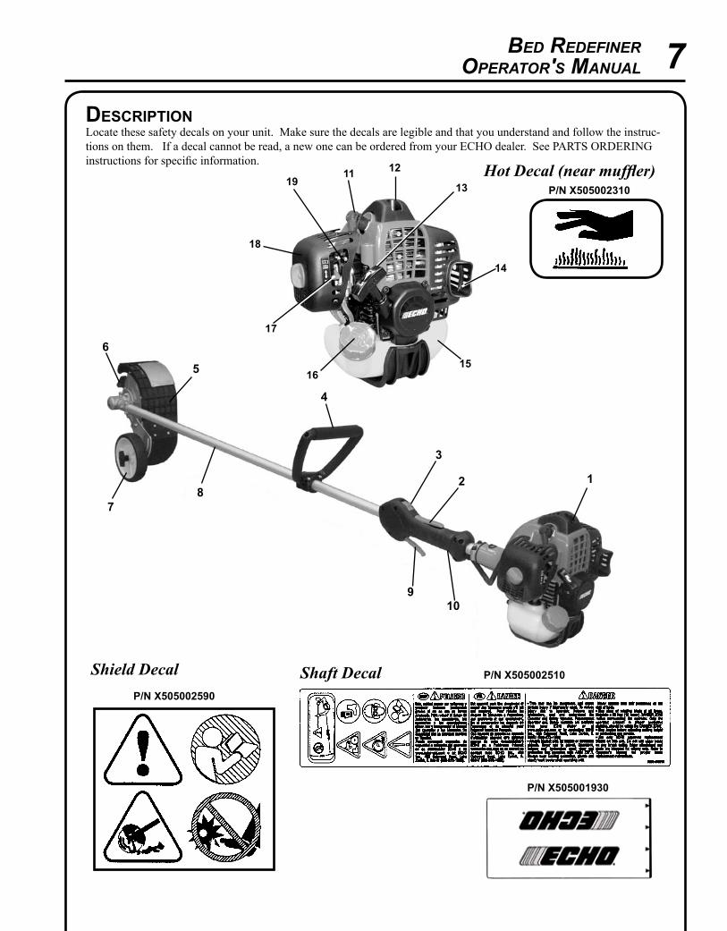
Bed RedefineROpeRatOR's Manual 7
1
4
5
6
78
9
2
3
Shaft Decal
descrIptIonLocate these safety decals on your unit. Make sure the decals are legible and that you understand and follow the instruc-tions on them. If a decal cannot be read, a new one can be ordered from your ECHO dealer. See PARTS ORDERING instructions for specific information.
P/n X505002310Hot Decal (near muffler)
P/n X505001930
10
13
12
14
1516
17
19
18
11
P/n X505002510
P/n X505002590
Shield Decal
8
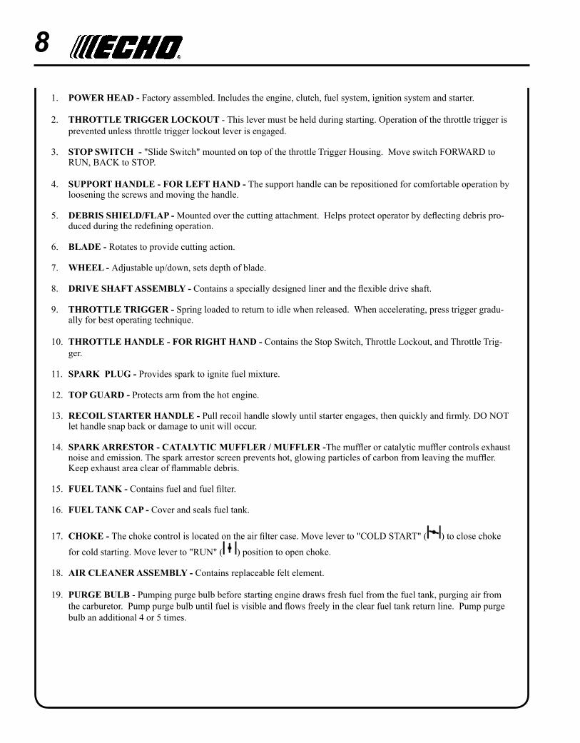
1. POWER hEAD - Factory assembled. Includes the engine, clutch, fuel system, ignition system and starter.
2. ThROTTLE TRIGGER LOCKOUT - This lever must be held during starting. Operation of the throttle trigger is prevented unless throttle trigger lockout lever is engaged.
3. sTOP sWITCh - "Slide Switch" mounted on top of the throttle Trigger Housing. Move switch FORWARD to RUN, BACK to STOP.
4. sUPPORT hANDLE - FOR LEFT hAND - The support handle can be repositioned for comfortable operation by loosening the screws and moving the handle.
5. DEBRIs shIELD/FLAP - Mounted over the cutting attachment. Helps protect operator by deflecting debris pro-duced during the redefining operation.
6. BLADE - Rotates to provide cutting action.
7. WhEEL - Adjustable up/down, sets depth of blade.
8. DRIVE shAFT AssEMBLy - Contains a specially designed liner and the flexible drive shaft.
9. ThROTTLE TRIGGER - Spring loaded to return to idle when released. When accelerating, press trigger gradu-ally for best operating technique.
10. ThROTTLE hANDLE - FOR RIGhT hAND - Contains the Stop Switch, Throttle Lockout, and Throttle Trig-ger.
11. sPARK PLUG - Provides spark to ignite fuel mixture.
12. TOP GUARD - Protects arm from the hot engine.
13. RECOIL sTARTER hANDLE - Pull recoil handle slowly until starter engages, then quickly and firmly. DO NOT let handle snap back or damage to unit will occur.
14. sPARK ARREsTOR - CATALyTIC MUFFLER / MUFFLER -The muffler or catalytic muffler controls exhaust noise and emission. The spark arrestor screen prevents hot, glowing particles of carbon from leaving the muffler. Keep exhaust area clear of flammable debris.
15. FUEL TANK - Contains fuel and fuel filter.
16. FUEL TANK CAP - Cover and seals fuel tank.
17. ChOKE - The choke control is located on the air filter case. Move lever to "COLD START" ( ) to close choke
for cold starting. Move lever to "RUN" ( ) position to open choke.
18. AIR CLEANER AssEMBLy - Contains replaceable felt element.
19. PURGE BULB - Pumping purge bulb before starting engine draws fresh fuel from the fuel tank, purging air from the carburetor. Pump purge bulb until fuel is visible and flows freely in the clear fuel tank return line. Pump purge bulb an additional 4 or 5 times.
Bed RedefineROpeRatOR's Manual 9
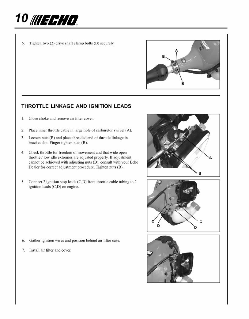
assembly
Parts Required: Power head, Drive Shaft Assembly
drIve shaft/power head
1. Stand power head upright on a level surface.
2. Loosen the two (2) drive shaft clamp bolts (B) at engine drive shaft clamp, and remove center drive shaft location bolt (A).
3. Remove dust cap and carefully fit drive shaft assembly to engine making sure that inner drive shaft engages into clutch mount.
4. Turn drive shaft housing until locating hole lines up with location hole in clamp and install center drive shaft location bolt (A).
NOTEGear Housing must be aligned properly with engine. Aligning cen-ter locating hole in driveshaft housing with center drive shaft bolt (A) provides correct alignment.
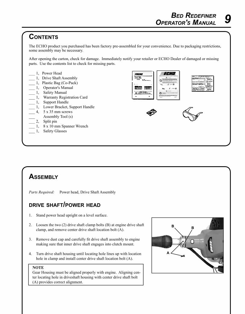
contentsThe ECHO product you purchased has been factory pre-assembled for your convenience. Due to packaging restrictions, some assembly may be necessary.
After opening the carton, check for damage. Immediately notify your retailer or ECHO Dealer of damaged or missing parts. Use the contents list to check for missing parts.
___ 1, Power Head___ 1, Drive Shaft Assembly___ 1, Plastic Bag (Co-Pack)___ 1, Operator's Manual___ 1, Safety Manual ___ 1, Warranty Registration Card___ 1, Support Handle___ 1, Lower Bracket, Support Handle___ 4, 5 x 35 mm screws___ Assembly Tool (s)___ 2, Split pin___ 1, 8 x 10 mm Spanner Wrench___ 1, Safety Glasses
a
B B
10
5. Tighten two (2) drive shaft clamp bolts (B) securely.
aB
B
a
B
CD
CD
throttle lInkage and IgnItIon leads
1. Close choke and remove air filter cover.
2. Place inner throttle cable in large hole of carburetor swivel (A).
3. Loosen nuts (B) and place threaded end of throttle linkage in bracket slot. Finger tighten nuts (B).
4. Check throttle for freedom of movement and that wide open throttle / low idle extremes are adjusted properly. If adjustment cannot be achieved with adjusting nuts (B), consult with your Echo Dealer for correct adjustment procedure. Tighten nuts (B).
5. Connect 2 ignition stop leads (C,D) from throttle cable tubing to 2 ignition leads (C,D) on engine.
6. Gather ignition wires and position behind air filter case.
7. Install air filter and cover.
Bed RedefineROpeRatOR's Manual 11
support handle
Parts Required: Support Handle, Lower Bracket, 4 - 5 x 35 mm screws
NOTE Label shows minimum spacing for front handle location.
1. Assemble front handle and bracket loosely to drive shaft.
2. Position front handle in comfortable operating position and tighten screws. MIN
SPaCing
edger blade InstallatIon
1. Remove bed redefining blade as shown in “Blade Replacement” Section. Discard used split pin.
2. Do not remove inner blade adapter (A) or locking tool (B).
3. Install and center edger blade (C) on inner adapter.
4. Install outer adapter (D) and nut.
5. Tighten nut firmly, counterclockwise.
6. Remove locking tool (B).
7. Install new split pin (F) to secure nut.
a
B
F
C
DE
12
fuel
NOTICE: Use of unmixed, improperly mixed, or fuel older than 90 days, (stale fuel), may cause hard starting, poor performance, or severe engine damage and void the product warranty. Read and follow instructions in the Storage section of this manual.
warningAlternative fuels, such as E-15 (15% ethanol), E-85 (85% ethanol) or any fuels not meeting ECHO requirements are NOT approved for use in ECHO 2-stroke gasoline engines. Use of alternative fuels may cause performance prob-lems, loss of power, overheating, fuel vapor lock, and unintended machine operation, including, but not limited to, improper clutch engagement. Alternative fuels may also cause premature deterioration of fuel lines, gaskets, carbu-retors and other engine components.
Fuel Requirements Gasoline - Use 89 Octane [R+M/2] (mid grade or higher) gasoline known to be good quality. Gasoline may contain up to 10% Ethanol (grain alcohol) or 15% MTBE (methyl tertiary-butyl ether). Gasoline containing methanol (wood alcohol) is NOT approved.
warningMoving parts can amputate fingers or cause severe injuries. Keep hands, clothing and loose objects away from all openings. Always stop engine, disconnect spark plug, and make sure all moving parts have come to a complete stop before removing obstructions, clearing debris, or servicing unit.
operatIon
warningOperation of this equipment may create sparks that can start fires around dry vegetation. This unit is equipped with a spark arrestor and a spark arrestor may be required. The operator should contact local fire agencies for laws or regulations relating to fire prevention requirements.
Two stroke Oil - A two-stroke engine oil meeting ISO-L-EGD (ISO/CD 13738) and J.A.S.O.FD Standards must be used. Echo brand premium Power Blend X TM Universal 2-Stroke Oil meets these standards. Engine problems due to in-adequate lubrication caused by failure to use an ISO-L-EGD (ISO/CD 13738) and J.A.S.O.FD certified oil, such as Echo premium Power Blend X TM, will void the two-stroke engine warranty.
IMPORTANT Echo premium Power Blend X TM Universal 2-Stroke Oil may be mixed at 50:1 ratio for application in all Echo en-gines sold in the past regardless of ratio specified in those manuals.
Bed RedefineROpeRatOR's Manual 13
IMPORTANT Stored fuel ages. Do not mix more fuel than you expect to use in thirty (30) days, ninety (90) days when a fuel sta-bilizer is added.
IMPORTANT Stored two-stroke fuel may separate. ALWAYS shake fuel container thor-oughly before each use.
Handling Fuel
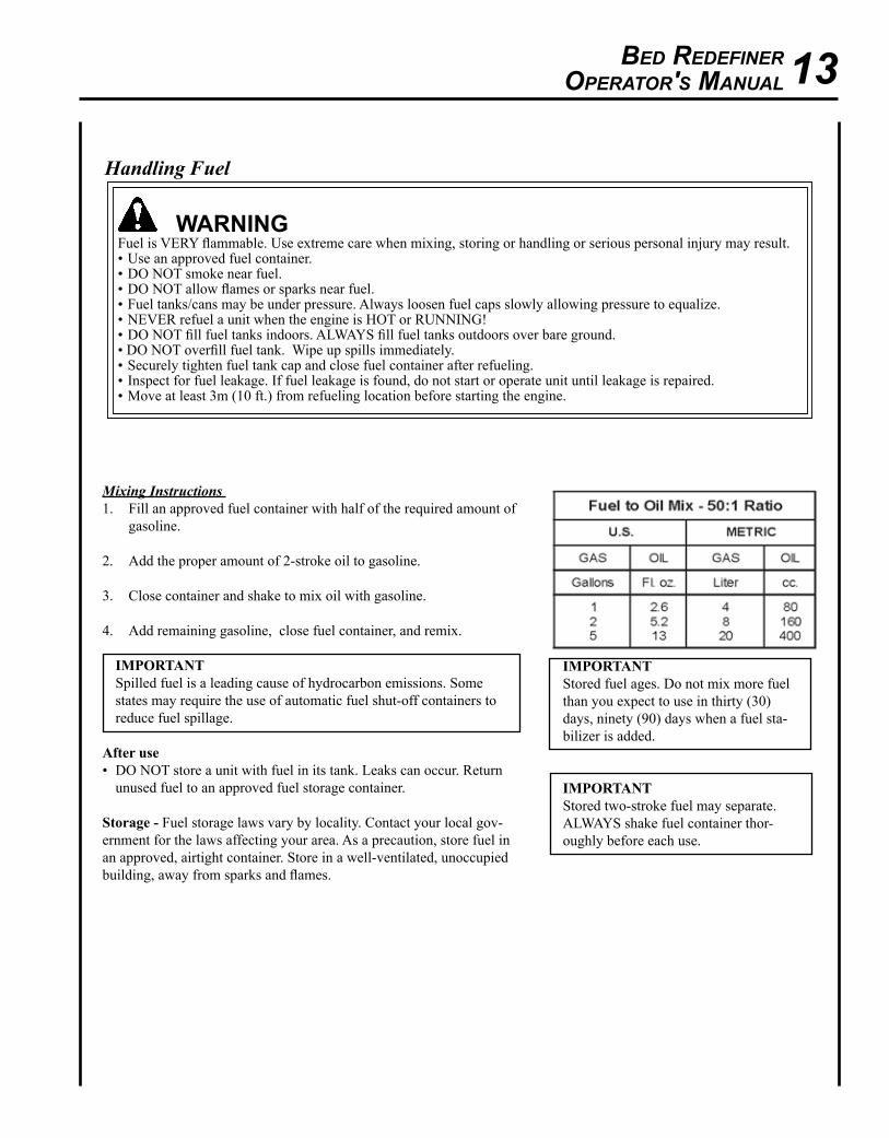
warningFuel is VERY flammable. Use extreme care when mixing, storing or handling or serious personal injury may result.• Use an approved fuel container. • DO NOT smoke near fuel.• DO NOT allow flames or sparks near fuel.• Fuel tanks/cans may be under pressure. Always loosen fuel caps slowly allowing pressure to equalize.• NEVER refuel a unit when the engine is HOT or RUNNING!• DO NOT fill fuel tanks indoors. ALWAYS fill fuel tanks outdoors over bare ground.• DO NOT overfill fuel tank. Wipe up spills immediately.• Securely tighten fuel tank cap and close fuel container after refueling.• Inspect for fuel leakage. If fuel leakage is found, do not start or operate unit until leakage is repaired.• Move at least 3m (10 ft.) from refueling location before starting the engine.
Mixing Instructions 1. Fill an approved fuel container with half of the required amount of
gasoline.
2. Add the proper amount of 2-stroke oil to gasoline.
3. Close container and shake to mix oil with gasoline.
4. Add remaining gasoline, close fuel container, and remix.
IMPORTANT Spilled fuel is a leading cause of hydrocarbon emissions. Some states may require the use of automatic fuel shut-off containers to reduce fuel spillage.
After use• DO NOT store a unit with fuel in its tank. Leaks can occur. Return
unused fuel to an approved fuel storage container.
storage - Fuel storage laws vary by locality. Contact your local gov-ernment for the laws affecting your area. As a precaution, store fuel in an approved, airtight container. Store in a well-ventilated, unoccupied building, away from sparks and flames.
14
startIng cold engIne
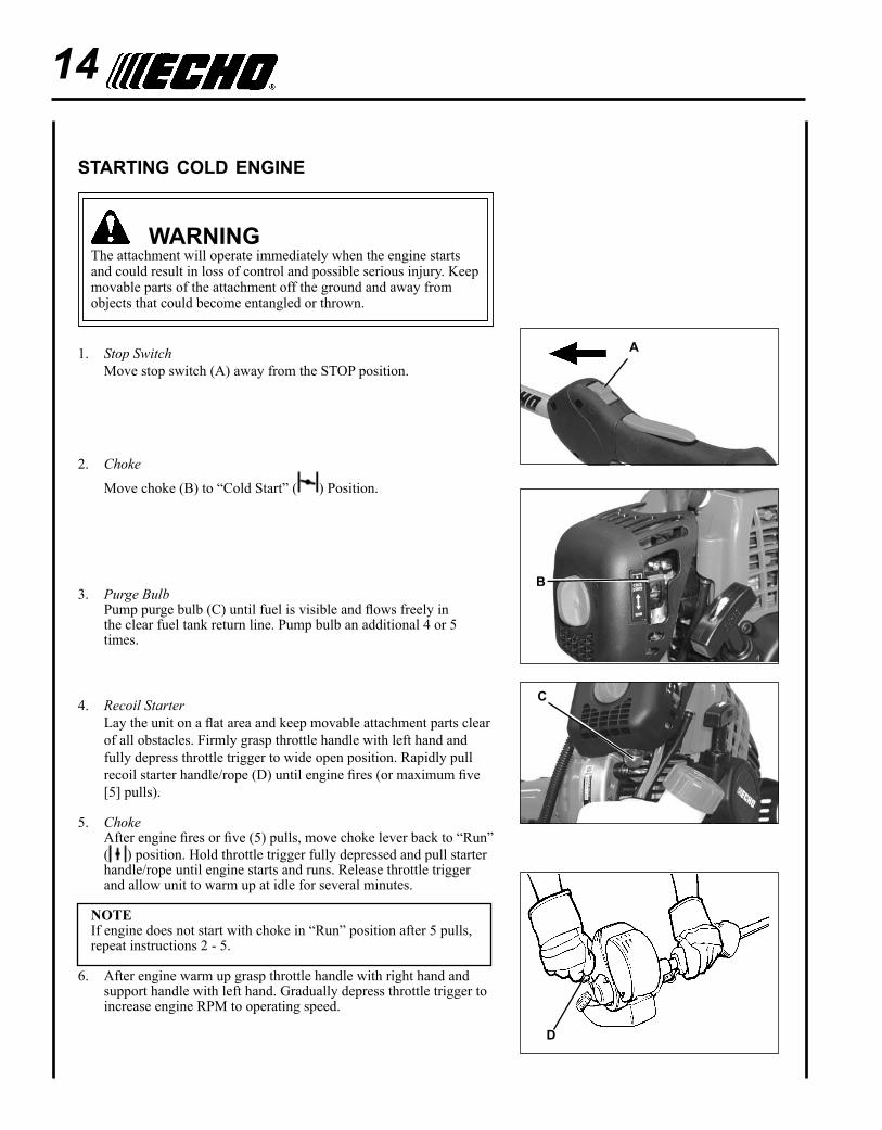
warningThe attachment will operate immediately when the engine starts and could result in loss of control and possible serious injury. Keep movable parts of the attachment off the ground and away from objects that could become entangled or thrown.
1. Stop Switch Move stop switch (A) away from the STOP position.
2. Choke
Move choke (B) to “Cold Start” ( ) Position.
3. Purge Bulb Pump purge bulb (C) until fuel is visible and flows freely in
the clear fuel tank return line. Pump bulb an additional 4 or 5 times.
4. Recoil Starter Lay the unit on a flat area and keep movable attachment parts clear
of all obstacles. Firmly grasp throttle handle with left hand and fully depress throttle trigger to wide open position. Rapidly pull recoil starter handle/rope (D) until engine fires (or maximum five [5] pulls).
5. Choke After engine fires or five (5) pulls, move choke lever back to “Run”
( ) position. Hold throttle trigger fully depressed and pull starter handle/rope until engine starts and runs. Release throttle trigger and allow unit to warm up at idle for several minutes.
NOTEIf engine does not start with choke in “Run” position after 5 pulls, repeat instructions 2 - 5.
6. After engine warm up grasp throttle handle with right hand and support handle with left hand. Gradually depress throttle trigger to increase engine RPM to operating speed.
a
D
B
C
Bed RedefineROpeRatOR's Manual 15
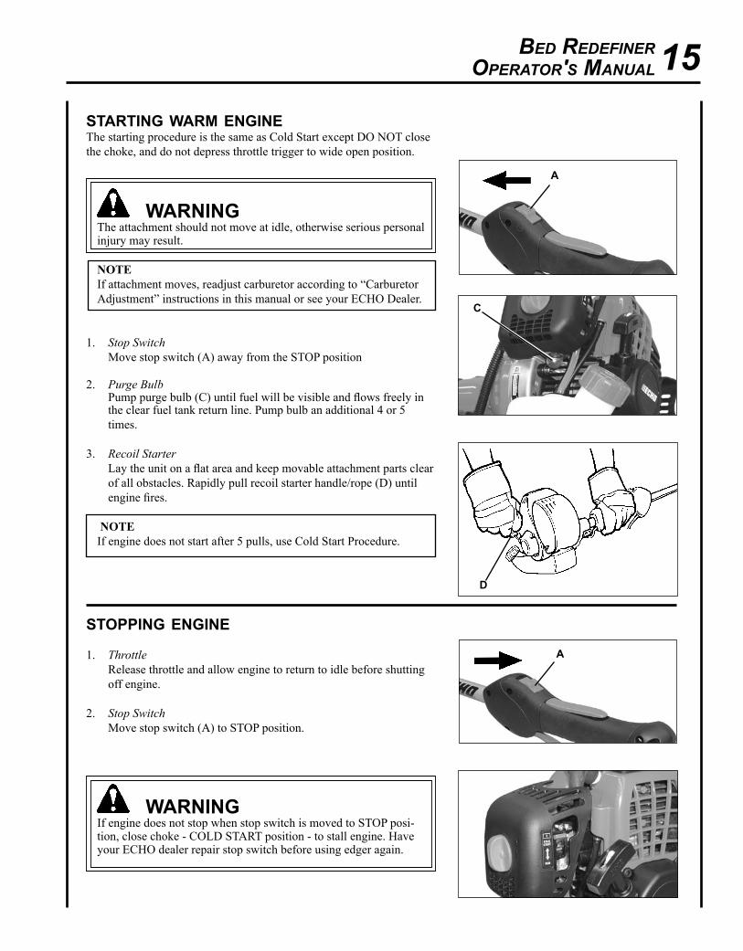
startIng warm engIneThe starting procedure is the same as Cold Start except DO NOT close the choke, and do not depress throttle trigger to wide open position.
warningThe attachment should not move at idle, otherwise serious personal injury may result.
NOTEIf attachment moves, readjust carburetor according to “Carburetor Adjustment” instructions in this manual or see your ECHO Dealer.
1. Stop Switch Move stop switch (A) away from the STOP position
2. Purge Bulb Pump purge bulb (C) until fuel will be visible and flows freely in
the clear fuel tank return line. Pump bulb an additional 4 or 5 times.
3. Recoil Starter Lay the unit on a flat area and keep movable attachment parts clear
of all obstacles. Rapidly pull recoil starter handle/rope (D) until engine fires.
NOTEIf engine does not start after 5 pulls, use Cold Start Procedure.
stoppIng engIne
1. Throttle Release throttle and allow engine to return to idle before shutting off engine.
2. Stop Switch Move stop switch (A) to STOP position.
warningIf engine does not stop when stop switch is moved to STOP posi-tion, close choke - COLD START position - to stall engine. Have your ECHO dealer repair stop switch before using edger again.
a
D
a
C

16
NOTE For best results, use BRD redefining blade (provided with unit) ONLY for redefining existing bed edges. For edging next to curbs, sidewalks, or other hard surfaces, remove redefining blade and install ECHO Approved Premium Power Edger blade. Use of redefining blade next to hard surfaces, can lead to premature blade wear.
1. Always grip throttle handle with right hand, and support handle with left hand.
2. Before using Redefiner, check the area and remove objects that could be thrown.
3. Carefully plan your direction of travel. Walk outside of bed. Be aware of curbs or other obstacles.
4. Work with body turned toward engine as shown. Travel in direc-tion of arrow, pulling rather than pushing unit. Carefully watch bed edge and direction of travel. Do NOT walk backwards.
IMPORTANT Do not walk towards gear case while operating unit with redefin-ing blade installed, otherwise poor performance or damage to unit could occur.
5. When starting to work, run the engine at full throttle, and lower the blade gently into the ground. Travel around perimeter of bed, allowing the Redefiner to improve bed's edge.
6. Do not force the blade. Move only as quickly as conditions will al-low. If performance suffers or engine RPM drops, reduce walking speed or decrease blade depth and allow engine RPM to return to normal before continuing.
NOTE Blade height may need to be adjusted due to differences in height between the bed and the top of the grass.
warning Never adjust blade height while engine is running, otherwise seri-ous personal injury may result.
7. Loosen adjustment knob (A) and adjust the blade’s depth of cut. Tighten adjustment knob (A) when desired blade height is achieved.
operatIng technIques
warningEngine exhaust IS HOT, and contains Carbon Monoxide (CO), a poison gas. Breathing CO can cause unconscious-ness, serious injury, or death. Exhaust can cause serious burns. ALWAYS position unit so that exhaust is directed away from your face and body.
warningBefore operating unit, be sure to read and understand the entire Operator’s Manual to avoid the chance of serious personal injury.
a
inCrEaSEDEPTH
DECrEaSEDEPTH
Bed RedefineROpeRatOR's Manual 17
8. If shield clogs with mud or debris, do not hit unit against hard surfaces to clean, or damage to unit may occur. Stop engine and unclog shield with a suitable tool.
IMPORTANT Be sure blade has completely stopped spinning before setting unit on concrete or other hard surface. Never allow spinning blade to contact hard surfaces. Carbide teeth on blade can break, or damage to surface can occur.
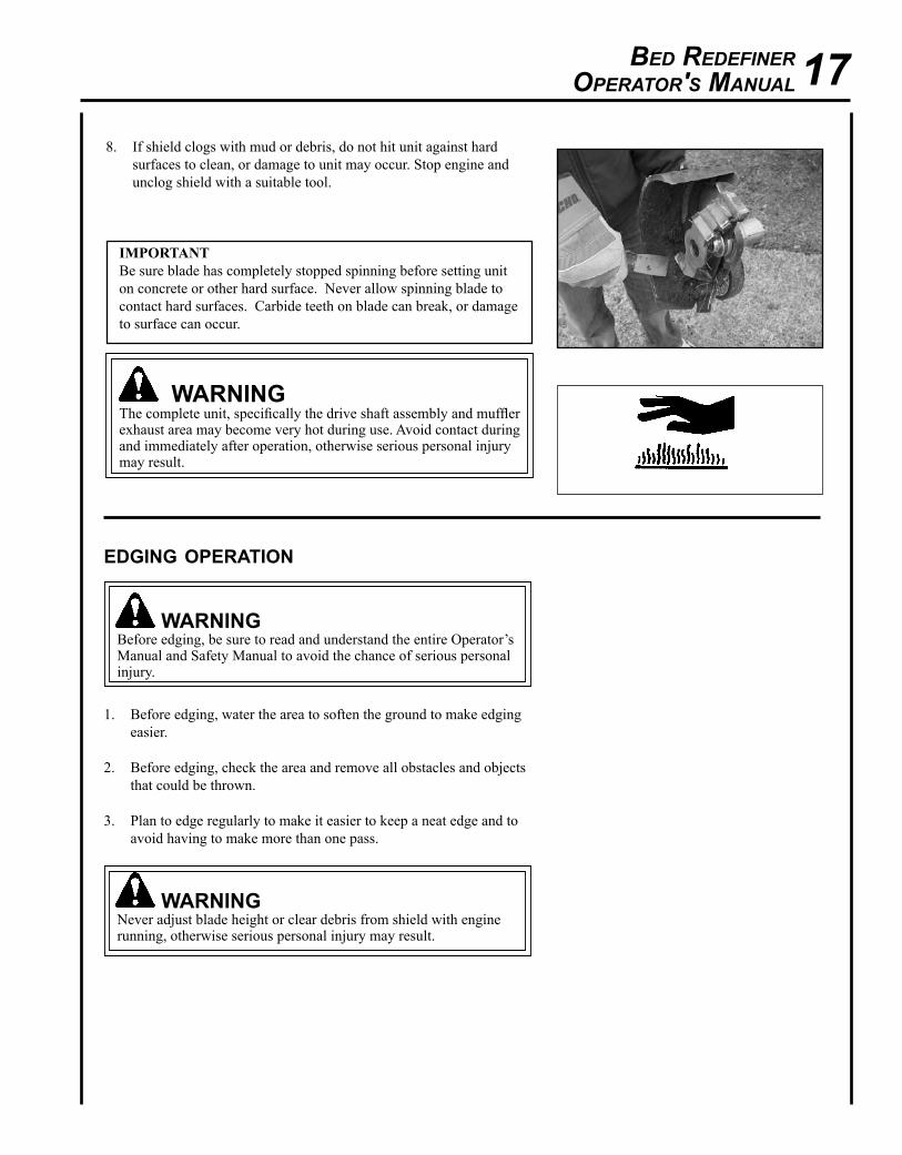
warningThe complete unit, specifically the drive shaft assembly and muffler exhaust area may become very hot during use. Avoid contact during and immediately after operation, otherwise serious personal injury may result.
edgIng operatIon
warningBefore edging, be sure to read and understand the entire Operator’s Manual and Safety Manual to avoid the chance of serious personal injury.
1. Before edging, water the area to soften the ground to make edging easier.
2. Before edging, check the area and remove all obstacles and objects that could be thrown.
3. Plan to edge regularly to make it easier to keep a neat edge and to avoid having to make more than one pass.
warningNever adjust blade height or clear debris from shield with engine running, otherwise serious personal injury may result.
18
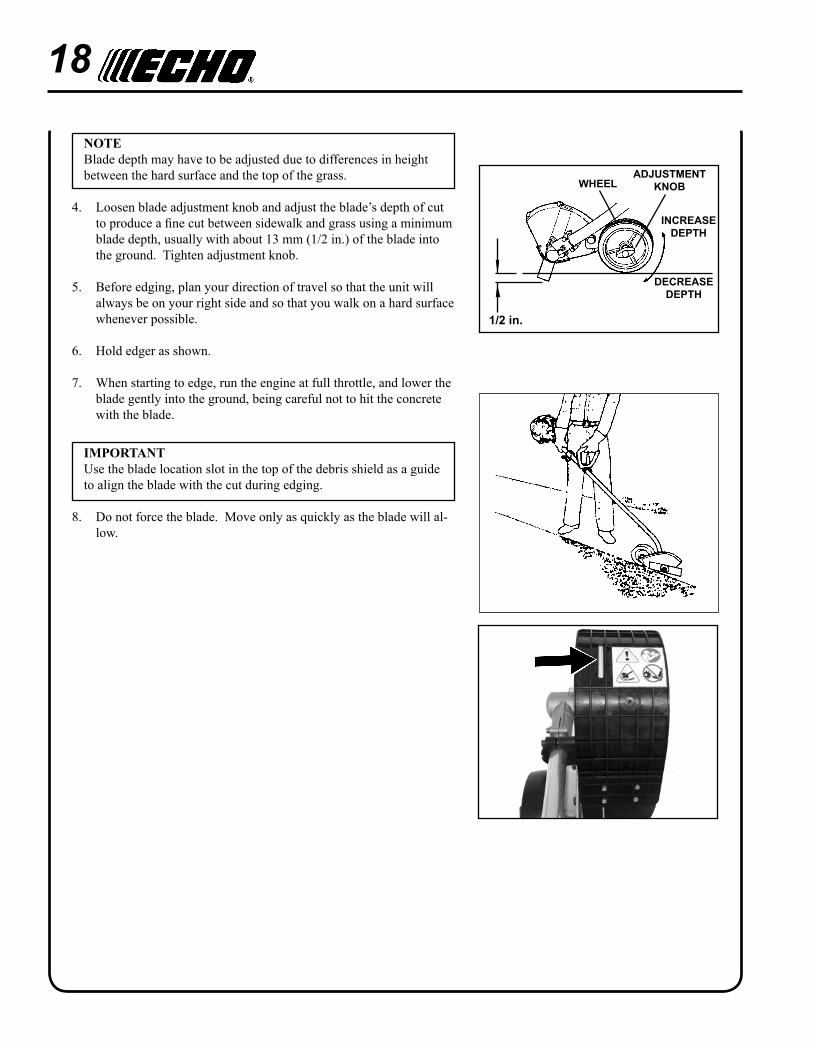
NOTEBlade depth may have to be adjusted due to differences in height between the hard surface and the top of the grass.
4. Loosen blade adjustment knob and adjust the blade’s depth of cut to produce a fine cut between sidewalk and grass using a minimum blade depth, usually with about 13 mm (1/2 in.) of the blade into the ground. Tighten adjustment knob.
5. Before edging, plan your direction of travel so that the unit will always be on your right side and so that you walk on a hard surface whenever possible.
6. Hold edger as shown.
7. When starting to edge, run the engine at full throttle, and lower the blade gently into the ground, being careful not to hit the concrete with the blade.
IMPORTANTUse the blade location slot in the top of the debris shield as a guide to align the blade with the cut during edging.
8. Do not force the blade. Move only as quickly as the blade will al-low.
inCrEaSEDEPTH
wHEELADJUSTMENT
KnOB
DECrEaSEDEPTH
1/2 in.
Bed RedefineROpeRatOR's Manual 19
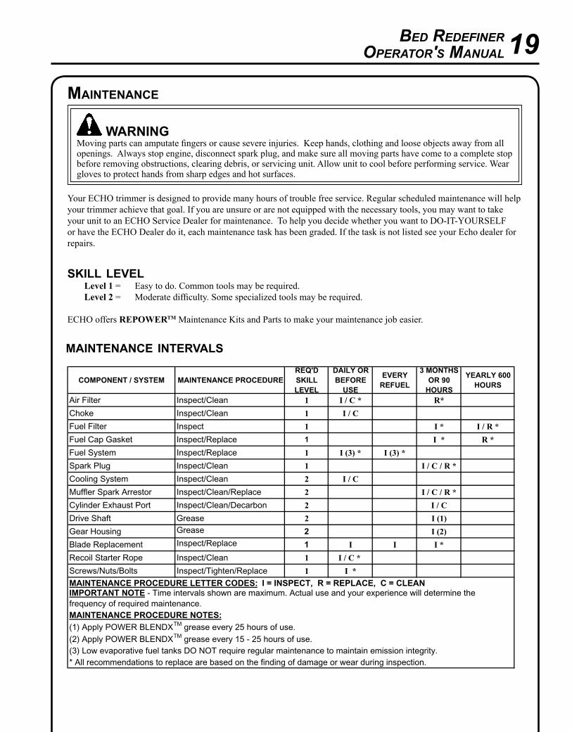
maIntenance Intervals
COMPONENT / SYSTEM MAINTENANCE PROCEDUREREQ'DSKILLLEVEL
DAILY OR BEFORE
USE
EVERYREFUEL
3 MONTHS OR 90
HOURS
YEARLY 600 HOURS
Air Filter Inspect/Clean 1 I / C * R*
Choke Inspect/Clean 1 I / C
Fuel Filter Inspect 1 I * I / R *
Fuel Cap Gasket Inspect/Replace 1 I * R *
Fuel System Inspect/Replace 1 I (3) * I (3) *
Spark Plug Inspect/Clean 1 I / C / R *
Cooling System Inspect/Clean 2 I / C
Muffler Spark Arrestor Inspect/Clean/Replace 2 I / C / R *
Cylinder Exhaust Port Inspect/Clean/Decarbon 2 I / C
Drive Shaft Grease 2 I (1)
Gear Housing Grease 2 I (2)
Blade Replacement Inspect/Replace 1 I I I *
Recoil Starter Rope Inspect/Clean 1 I / C *
Screws/Nuts/Bolts Inspect/Tighten/Replace 1 I *
(2) Apply POWER BLENDXTM grease every 15 - 25 hours of use.(3) Low evaporative fuel tanks DO NOT require regular maintenance to maintain emission integrity.* All recommendations to replace are based on the finding of damage or wear during inspection.
MAINTENANCE PROCEDURE LETTER CODES: I = INSPECT, R = REPLACE, C = CLEANIMPORTANT NOTE - Time intervals shown are maximum. Actual use and your experience will determine the frequency of required maintenance.MAINTENANCE PROCEDURE NOTES:(1) Apply POWER BLENDXTM grease every 25 hours of use.
Your ECHO trimmer is designed to provide many hours of trouble free service. Regular scheduled maintenance will help your trimmer achieve that goal. If you are unsure or are not equipped with the necessary tools, you may want to take your unit to an ECHO Service Dealer for maintenance. To help you decide whether you want to DO-IT-YOURSELF or have the ECHO Dealer do it, each maintenance task has been graded. If the task is not listed see your Echo dealer for repairs.
skIll level Level 1 = Easy to do. Common tools may be required. Level 2 = Moderate difficulty. Some specialized tools may be required. ECHO offers REPOWERTM Maintenance Kits and Parts to make your maintenance job easier.
warningMoving parts can amputate fingers or cause severe injuries. Keep hands, clothing and loose objects away from all openings. Always stop engine, disconnect spark plug, and make sure all moving parts have come to a complete stop before removing obstructions, clearing debris, or servicing unit. Allow unit to cool before performing service. Wear gloves to protect hands from sharp edges and hot surfaces.
maIntenance
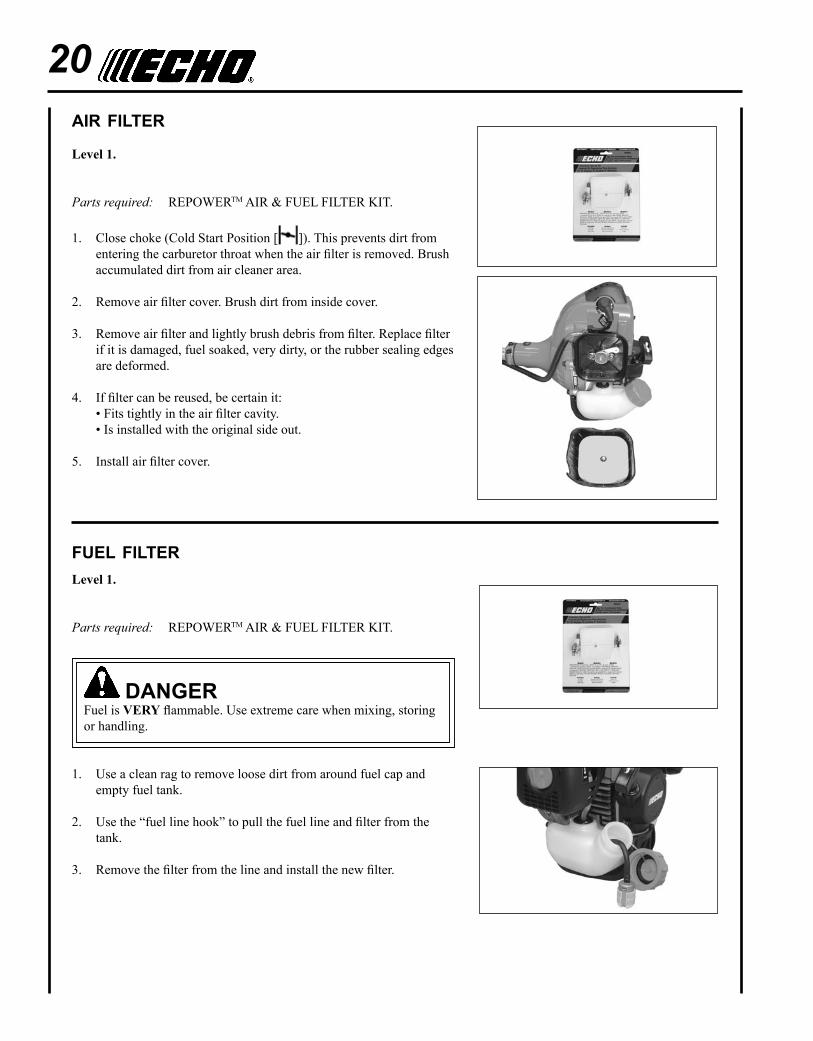
20aIr fIlter
Level 1.
Parts required: REPOWERTM AIR & FUEL FILTER KIT.
1. Close choke (Cold Start Position [ ]). This prevents dirt from entering the carburetor throat when the air filter is removed. Brush accumulated dirt from air cleaner area.
2. Remove air filter cover. Brush dirt from inside cover.
3. Remove air filter and lightly brush debris from filter. Replace filter if it is damaged, fuel soaked, very dirty, or the rubber sealing edges are deformed.
4. If filter can be reused, be certain it: • Fits tightly in the air filter cavity. • Is installed with the original side out.
5. Install air filter cover.
fuel fIlterLevel 1.
Parts required: REPOWERTM AIR & FUEL FILTER KIT.
DangErFuel is VERy flammable. Use extreme care when mixing, storing or handling.
1. Use a clean rag to remove loose dirt from around fuel cap and empty fuel tank.
2. Use the “fuel line hook” to pull the fuel line and filter from the tank.
3. Remove the filter from the line and install the new filter.
Bed RedefineROpeRatOR's Manual 21
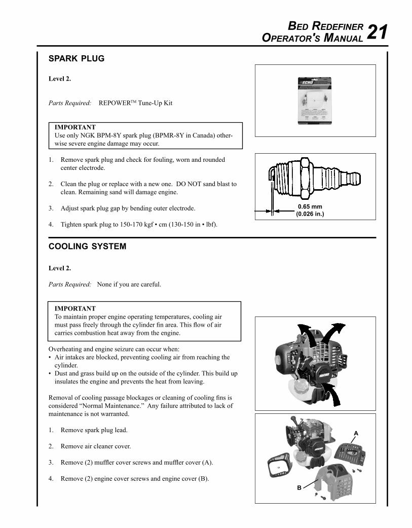
spark plug
Level 2.
Parts Required: REPOWERTM Tune-Up Kit
IMPORTANTUse only NGK BPM-8Y spark plug (BPMR-8Y in Canada) other-wise severe engine damage may occur.
1. Remove spark plug and check for fouling, worn and rounded center electrode.
2. Clean the plug or replace with a new one. DO NOT sand blast to clean. Remaining sand will damage engine.
3. Adjust spark plug gap by bending outer electrode.
4. Tighten spark plug to 150-170 kgf • cm (130-150 in • lbf).
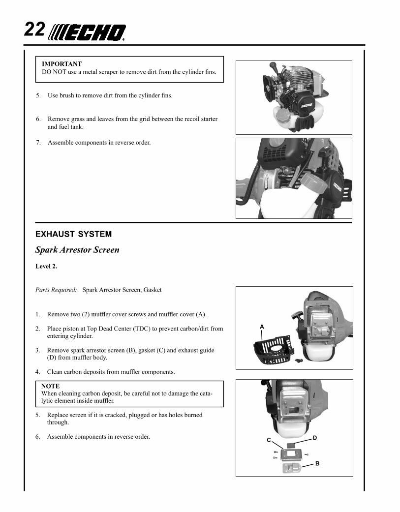
coolIng system
Level 2.
Parts Required: None if you are careful.
IMPORTANT To maintain proper engine operating temperatures, cooling air must pass freely through the cylinder fin area. This flow of air carries combustion heat away from the engine.
Overheating and engine seizure can occur when:• Air intakes are blocked, preventing cooling air from reaching the
cylinder.• Dust and grass build up on the outside of the cylinder. This build up
insulates the engine and prevents the heat from leaving.
Removal of cooling passage blockages or cleaning of cooling fins is considered “Normal Maintenance.” Any failure attributed to lack of maintenance is not warranted.
1. Remove spark plug lead.
2. Remove air cleaner cover.
3. Remove (2) muffler cover screws and muffler cover (A).
4. Remove (2) engine cover screws and engine cover (B).
0.65 mm(0.026 in.)
a
B
22
exhaust system
Spark Arrestor Screen
Level 2.
Parts Required: Spark Arrestor Screen, Gasket
1. Remove two (2) muffler cover screws and muffler cover (A).
2. Place piston at Top Dead Center (TDC) to prevent carbon/dirt from entering cylinder.
3. Remove spark arrestor screen (B), gasket (C) and exhaust guide (D) from muffler body.
4. Clean carbon deposits from muffler components.
NOTEWhen cleaning carbon deposit, be careful not to damage the cata-lytic element inside muffler.
5. Replace screen if it is cracked, plugged or has holes burned through.
6. Assemble components in reverse order.
IMPORTANT DO NOT use a metal scraper to remove dirt from the cylinder fins.
5. Use brush to remove dirt from the cylinder fins.
6. Remove grass and leaves from the grid between the recoil starter and fuel tank.
7. Assemble components in reverse order.
a
B
C D
Bed RedefineROpeRatOR's Manual 23
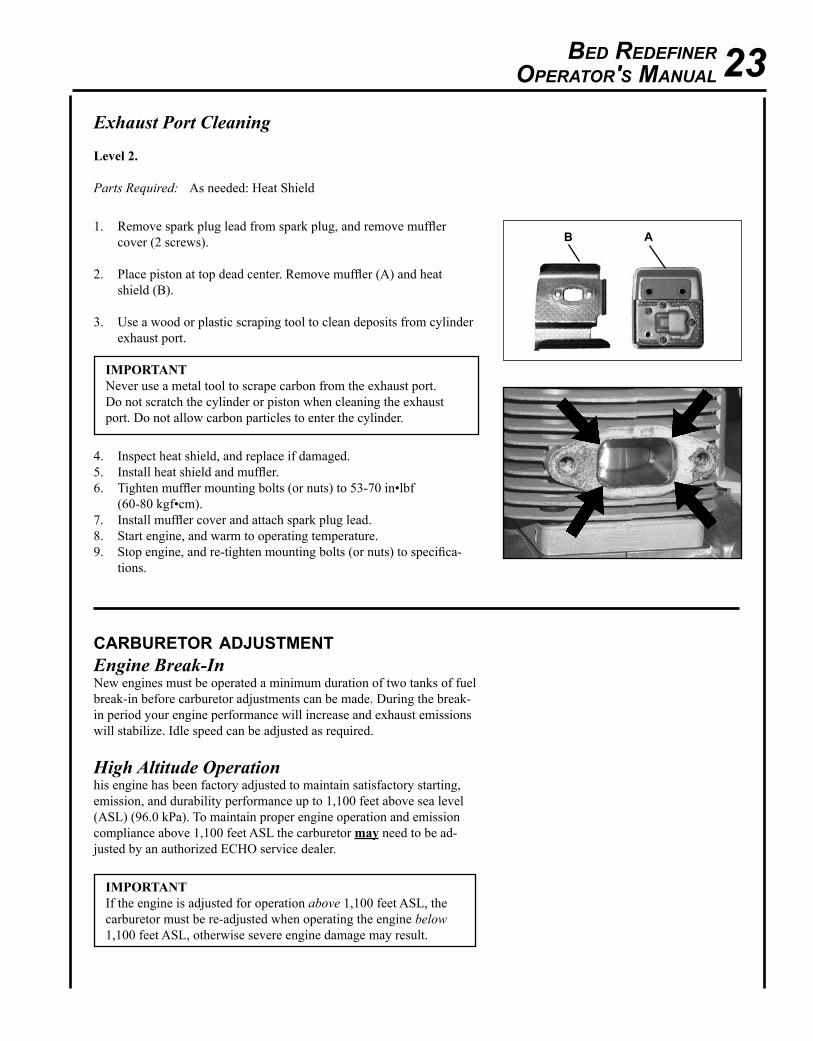
Exhaust Port Cleaning
Level 2.
Parts Required: As needed: Heat Shield
1. Remove spark plug lead from spark plug, and remove muffler cover (2 screws).
2. Place piston at top dead center. Remove muffler (A) and heat shield (B).
3. Use a wood or plastic scraping tool to clean deposits from cylinder exhaust port.
IMPORTANT Never use a metal tool to scrape carbon from the exhaust port. Do not scratch the cylinder or piston when cleaning the exhaust port. Do not allow carbon particles to enter the cylinder.
4. Inspect heat shield, and replace if damaged.5. Install heat shield and muffler.6. Tighten muffler mounting bolts (or nuts) to 53-70 in•lbf
(60-80 kgf•cm).7. Install muffler cover and attach spark plug lead. 8. Start engine, and warm to operating temperature.9. Stop engine, and re-tighten mounting bolts (or nuts) to specifica-
tions.
aB
carburetor adjustmentEngine Break-InNew engines must be operated a minimum duration of two tanks of fuel break-in before carburetor adjustments can be made. During the break-in period your engine performance will increase and exhaust emissions will stabilize. Idle speed can be adjusted as required.
High Altitude Operationhis engine has been factory adjusted to maintain satisfactory starting, emission, and durability performance up to 1,100 feet above sea level (ASL) (96.0 kPa). To maintain proper engine operation and emission compliance above 1,100 feet ASL the carburetor may need to be ad-justed by an authorized ECHO service dealer.
IMPORTANT If the engine is adjusted for operation above 1,100 feet ASL, the carburetor must be re-adjusted when operating the engine below 1,100 feet ASL, otherwise severe engine damage may result.
24Level 2.
Parts required: None
NOTE Every unit is run at the factory and the carburetor is set in compli-ance with emission regulations. Carburetor adjustments, other than idle speed, must be performed by an authorized ECHO dealer.
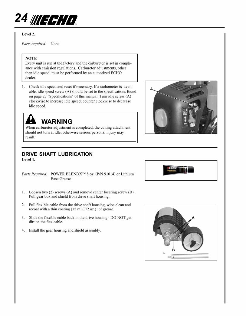
1. Check idle speed and reset if necessary. If a tachometer is avail-able, idle speed screw (A) should be set to the specifications found on page 27 "Specifications" of this manual. Turn idle screw (A) clockwise to increase idle speed; counter clockwise to decrease idle speed.
warningWhen carburetor adjustment is completed, the cutting attachment should not turn at idle, otherwise serious personal injury may result.
drIve shaft lubrIcatIonLevel 1.
Parts Required: POWER BLENDXTM 8 oz. (P/N 91014) or Lithium Base Grease.
1. Loosen two (2) screws (A) and remove center locating screw (B). Pull gear box and shield from drive shaft housing.
2. Pull flexible cable from the drive shaft housing, wipe clean and recoat with a thin coating [15 ml (1/2 oz.)] of grease.
3. Slide the flexible cable back in the drive housing. DO NOT get dirt on the flex cable.
4. Install the gear housing and shield assembly.
a
B
a
Bed RedefineROpeRatOR's Manual 25
blade replacement/lubrIcatIon
Level 1.
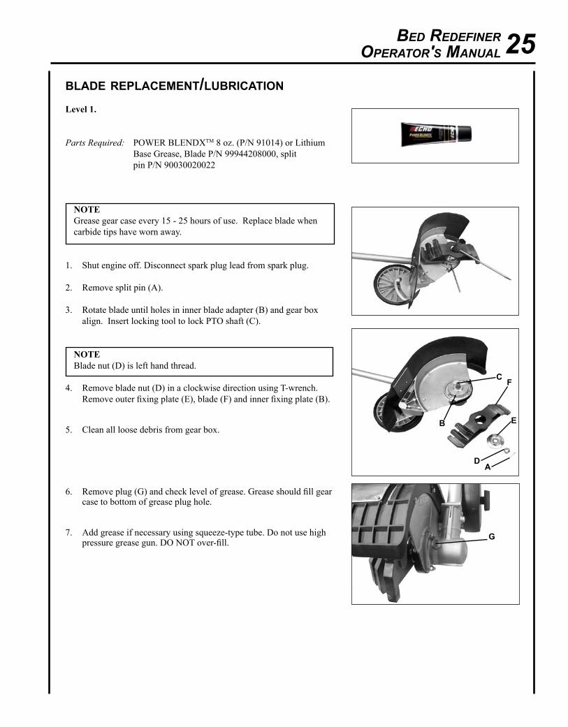
Parts Required: POWER BLENDXTM 8 oz. (P/N 91014) or Lithium Base Grease, Blade P/N 99944208000, split pin P/N 90030020022
NOTE Grease gear case every 15 - 25 hours of use. Replace blade when carbide tips have worn away.
1. Shut engine off. Disconnect spark plug lead from spark plug.
2. Remove split pin (A).
3. Rotate blade until holes in inner blade adapter (B) and gear box align. Insert locking tool to lock PTO shaft (C).
NOTE Blade nut (D) is left hand thread.
4. Remove blade nut (D) in a clockwise direction using T-wrench. Remove outer fixing plate (E), blade (F) and inner fixing plate (B).
5. Clean all loose debris from gear box.
6. Remove plug (G) and check level of grease. Grease should fill gear case to bottom of grease plug hole.
7. Add grease if necessary using squeeze-type tube. Do not use high pressure grease gun. DO NOT over-fill.
a
B
C
D
E
F
g
26
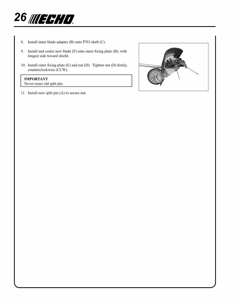
8. Install inner blade adapter (B) onto PTO shaft (C).
9. Install and center new blade (F) onto inner fixing plate (B), with longest side toward shield.
10. Install outer fixing plate (E) and nut (D). Tighten nut (D) firmly, counterclockwise (CCW).
IMPORTANT Never reuse old split pin.
11. Install new split pin (A) to secure nut.
Bed RedefineROpeRatOR's Manual 27
DangErFuel vapors are extremely flammable and may cause fire and/or explosion. Never test for ignition spark by ground-ing spark plug near cylinder plug hole, otherwise serious personal injury may result.
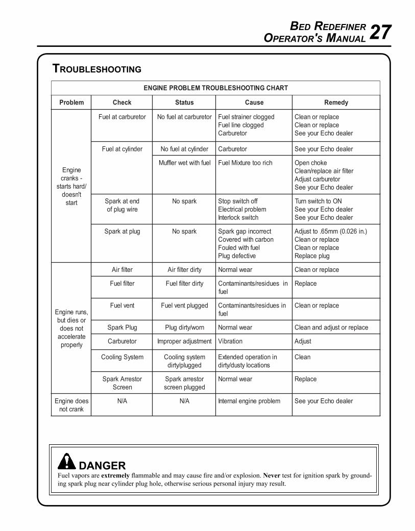
TraHCgniTOOHSELBUOrTMELBOrPEnignE
melborP kcehC sutatS esuaC ydemer
enignE-sknarc
/drahstratst'nseod
trats
roterubractaleuF roterubractaleufoN deggolcreniartsleuFdeggolcenilleuF
roterubraC
ecalperronaelCecalperronaelC
relaedohcEruoyeeS
rednilyctaleuF rednilyctaleufoN roterubraC relaedohcEruoyeeS
leufhtiwtewrelffuM hcirooterutxiMleuF ekohcnepOretlifriaecalper/naelC
roterubractsujdArelaedohcEruoyeeS
dnetakrapSeriwgulpfo
krapsoN ffohctiwspotSmelborplacirtcelE
hctiwskcolretnI
NOothctiwsnruTrelaedohcEruoyeeSrelaedohcEruoyeeS
gulptakrapS krapsoN tcerrocnipagkrapSnobrachtiwderevoC
leufhtiwdeluoFevitcefedgulP
).ni620.0(mm56.ottsujdAecalperronaelCecalperronaelC
gulpecalpeR
,snurenignEroseidtub
tonseodetarelecca
ylreporp
retlifriA ytridretlifriA raewlamroN ecalperronaelC
retlifleuF ytridretlifleuF seudiser/stnanimatnoC nileuf
ecalpeR
tnevleuF deggulptnevleuF niseudiser/stnanimatnoCleuf
ecalperronaelC
gulPkrapS nrow/ytridgulP raewlamroN ecalperrotsujdadnanaelC
roterubraC tnemtsujdareporpmI noitarbiV tsujdA
metsySgnilooC metsysgnilooCdeggulp/ytrid
ninoitarepodednetxEsnoitacolytsud/ytrid
naelC
rotserrAkrapSneercS
rotserrakrapSdeggulpneercs
raewlamroN ecalpeR
seodenignEknarcton
A/N A/N melborpenignelanretnI relaedohcEruoyeeS
troubleshootIng
28storage
warningDuring operation the muffler or catalytic muffler and surrounding cover become hot. Always keep exhaust area clear of flammable debris during transportation or when storing, otherwise serious property damage or personal injury may result.
Long Term Storage (over 30 days)
Do not store your unit for a prolonged period of time (30 days or longer) without performing protective storage mainte-nance which includes the following:
1. Store unit in a dry, dust free place, out of the reach of children.
DangErDo not store in enclosure where fuel fumes may accumulate or reach an open flame or spark.
2. Place the stop switch in the "STOP" position.
3. Remove accumulation of grease, oil, dirt and debris from exterior of unit.
4. Perform all periodic lubrication and services that are required.
5. Tighten all the screws and nuts.
6. Drain the fuel tank completely and pull the recoil starter handle several times to remove fuel from the carburetor.
7. Remove the spark plug and pour 7 cc (1/4 oz.) of fresh, clean, two-stroke engine oil into the cylinder through the spark plug hole.
A. Place a clean cloth over the spark plug hole.
B. Pull the recoil starter handle 2-3 times to distribute the oil inside the engine.
C. Observe the piston location through the spark plug hole. Pull the recoil handle slowly until the piston reaches the top of its travel and leave it there.
8. Install the spark plug (do not connect ignition cable).
Bed RedefineROpeRatOR's Manual 29
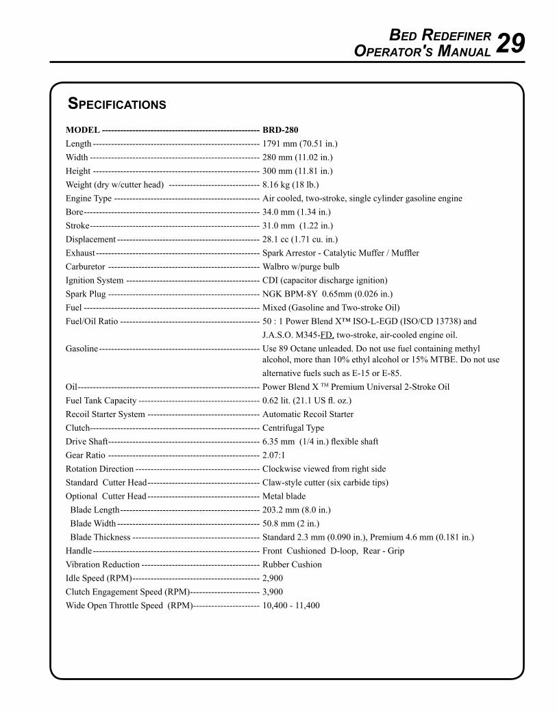
specIfIcatIons
MODEL ---------------------------------------------------- BRD-280Length ------------------------------------------------------- 1791 mm (70.51 in.)Width -------------------------------------------------------- 280 mm (11.02 in.)Height ------------------------------------------------------- 300 mm (11.81 in.)Weight (dry w/cutter head) ------------------------------ 8.16 kg (18 lb.) Engine Type ------------------------------------------------ Air cooled, two-stroke, single cylinder gasoline engineBore ---------------------------------------------------------- 34.0 mm (1.34 in.)Stroke -------------------------------------------------------- 31.0 mm (1.22 in.)Displacement ----------------------------------------------- 28.1 cc (1.71 cu. in.)Exhaust ------------------------------------------------------ Spark Arrestor - Catalytic Muffer / MufflerCarburetor -------------------------------------------------- Walbro w/purge bulbIgnition System -------------------------------------------- CDI (capacitor discharge ignition)Spark Plug -------------------------------------------------- NGK BPM-8Y 0.65mm (0.026 in.)Fuel ---------------------------------------------------------- Mixed (Gasoline and Two-stroke Oil)Fuel/Oil Ratio ---------------------------------------------- 50 : 1 Power Blend X™ ISO-L-EGD (ISO/CD 13738) and
J.A.S.O. M345-FD, two-stroke, air-cooled engine oil.Gasoline ----------------------------------------------------- Use 89 Octane unleaded. Do not use fuel containing methyl
alcohol, more than 10% ethyl alcohol or 15% MTBE. Do not use alternative fuels such as E-15 or E-85.
Oil ------------------------------------------------------------ Power Blend X TM Premium Universal 2-Stroke OilFuel Tank Capacity ---------------------------------------- 0.62 lit. (21.1 US fl. oz.)Recoil Starter System ------------------------------------- Automatic Recoil StarterClutch-------------------------------------------------------- Centrifugal TypeDrive Shaft -------------------------------------------------- 6.35 mm (1/4 in.) flexible shaftGear Ratio -------------------------------------------------- 2.07:1Rotation Direction ----------------------------------------- Clockwise viewed from right sideStandard Cutter Head ------------------------------------- Claw-style cutter (six carbide tips)Optional Cutter Head ------------------------------------- Metal blade Blade Length ---------------------------------------------- 203.2 mm (8.0 in.) Blade Width ----------------------------------------------- 50.8 mm (2 in.) Blade Thickness ------------------------------------------ Standard 2.3 mm (0.090 in.), Premium 4.6 mm (0.181 in.)Handle ------------------------------------------------------- Front Cushioned D-loop, Rear - GripVibration Reduction --------------------------------------- Rubber CushionIdle Speed (RPM) ------------------------------------------ 2,900Clutch Engagement Speed (RPM) ----------------------- 3,900Wide Open Throttle Speed (RPM) ---------------------- 10,400 - 11,400
30
warranty statements
ECHO LIMITED WARRANTY STATEMENT FOR PRODUCT SOLD IN USA AND CANADA BEGINNING 01/01/2010
ECHO'S RESPONSIBILITYECHO Incorporated’s Limited Warranty, provides to the original purchaser that this ECHO product is free from defects in material and workmanship. Under normal use and maintenance from date of purchase, ECHO agrees to repair or replace at ECHO’s discretion, any defective product free of charge at any authorized ECHO servicing dealer within listed below application time periods, limitations and exclusions. THIS LIMITED WARRANTY IS ONLY APPLICABLE TO ECHO PRODUCTS SOLD BY AUTHORIZED ECHO DEALERS. IT IS EXTENDED TO THE ORIGINAL PURCHASER ONLY, AND IS NOT TRANSFERABLE TO SUBSEQUENT OWNERS EXCEPT FOR EMISSION RELATED PARTS. Repair parts and accessories replaced under this warranty are warranted only for the balance of the original unit or accessory warranty period. Any damage caused by improper installation or improper maintenance is not covered by this warranty. All parts or products replaced under warranty become the property of ECHO, Inc. This warranty is separate from the Emission control warranty statement supplied with your new product. Please consult the Emission Control Warranty Statement for details regarding emission related parts. For a list of Authorized ECHO Dealers refer to WWW.ECHO-USA.COM or call 1-800-432-ECHO.
OWNER’S RESPONSIBILITYTo ensure trouble free warranty coverage it is important that you register your ECHO equipment on-line at WWW.ECHO-USA.COM or by fill-ing out the warranty registration card supplied with your unit. Registering your product confirms your warranty coverage and provides a direct link if we find it necessary to contact you.
The owner shall demonstrate reasonable care and use, and follow preventative maintenance, storage, fuel and oil usage as prescribed in the operator’s manual. Should a product difficulty occur, you must, at your expense, deliver or ship your ECHO unit to an authorized ECHO servicing dealer for warranty repairs (within the applicable warranty period), and arrange for pick-up or return of your unit after the repairs have been made. For your nearest authorized ECHO servicing dealer, call ECHO’s Dealer Referral Center, at 1-800-432-ECHO or you can locate an ECHO servicing dealer at WWW.ECHO-USA.COM. Should you require assistance or have questions concerning ECHO’s Warranty Statement, you can contact our Consumer Product Support Department at 1-800-673-1558 or contact us through the web at WWW.ECHO-USA.COM.
PRODUCT WARRANTY PERIOD
RESIDENTIAL APPLICATION • 5 YEAR WARRANTY - All units for residential, or non-income producing use will be covered by this limited warranty for five (5) years from
date of purchase.
EXCEPTIONS: • For two-stroke engine powered products, the electronic ignition module, flexible drive cables, SRM solid drive shafts, and TC tines
are warranted for the life* of the product on parts only.• Cutting attachments such as, but not limited to, bars, chains, sprockets, blades, and nylon trimmer heads for residential or non-income
producing use will be covered for failures due to defects in material or workmanship for a period of 60 days from original product purchase date. Any misuse from contact with concrete, rocks, or other structures is not covered by this warranty.
• ECHO’s Rapid Loader String Head carries a lifetime warranty on the line locking system, parts only; no labor. Refer to your operator’s manual for string head installation and maintenance instructions.
• All SB-Series and PRO ATTACHMENT SERIES Split Shaft attachments carry the same warranty duration as the units they are designed to fit.
COMMERCIAL APPLICATION • 1 YEAR WARRANTY - All Chain Saws, QuikVent Saws, and Cut-Off Saws for commercial, institutional, agricultural, industrial, or income
producing use will be covered by this limited warranty for one (1) year from the date of purchase.• 2 YEAR WARRANTY - All other units for commercial, institutional, agricultural, industrial, or income producing use will be covered by this
limited warranty for two (2) years from the date of purchase.
EXCEPTIONS: • For two-stroke engine powered products, the electronic ignition module, flexible drive cables, SRM solid drive shafts and TC tines,
are warranted for the life* of the product on parts only. • Cutting attachments such as, but not limited to, bars, chains, sprockets, blades, and nylon trimmer heads for commercial, institutional,
agricultural, industrial, rental, or income producing will be covered for failures due to defects in material or workmanship for a period of 30 days from original product purchase date. Any misuse from contact with concrete, rocks, or other structures is not covered by this warranty.
• ECHO’s Rapid Loader String Head carries a lifetime warranty on the line locking system, parts only; no labor. Refer to your operator’s manual for string head installation and maintenance instructions.
• All SB-Series and PRO ATTACHMENT SERIES Split Shaft attachments carry the same warranty duration as the units they are designed to fit.
RENTAL APPLICATION - 90 DAYS WARRANTY• Units for rental use will be covered against defects in material and workmanship for a period of 90 days from the date of purchase.
* ECHO’s liability under the “Lifetime” coverage is limited to furnishing parts specified under the PROdUCT wARRANTy PERIOd section of this warranty statement for “Life” free of charge for a period of ten (10) years after the date of the complete unit’s final production.
Bed RedefineROpeRatOR's Manual 31
PURCHASED REPAIR PARTS, SHORT BLOCKS AND ACCESSORIES• 90-day residential, or non-income producing warranty• 30-day commercial, institutional, agricultural, industrial, income producing, or rental application warranty
ATTENTION TWO-STROKE ENGINE POWER PRODUCT OWNERSThis ECHO two-stroke engine power product is a quality-engineered unit which has been manufactured to exact tolerances to provide superior performance. To help ensure the performance of the unit, it is required to use two-stroke oil which meets the ISO-L-EGD Standard per ISO/CD 13738 and JASO M345/FC/FD Standards. ECHO Power Blend™ Two-Stroke Oil is a premium two-stroke oil specifically formulated to meet ISO-L-EGD (ISO/CD 13738) and JASO M345/FC/FD Standards. The use of two-stroke oils designed for other applications, such as for outboard motors or lawnmowers can result in severe engine damage, and will void your two-stroke engine limited warranty.
THIS WARRANTY DOES NOT COVER DAMAGE CAUSED BY:• Lack of lubrication or engine failure, due to the use of two-stroke oils that do not meet the ISO-L-EGD (ISO/CD 13738) and JASO M345/
FC/FD Standards. Engine problems due to inadequate lubrication caused by failure to use an ISO-L-EGD compliant and JASO M345/FC/FD registered oil, will void the two-stroke engine limited warranty. ECHO Power Blend™ Two-Stroke Oil meets the ISO-L-EGD and JASO M345/FC/FD Standard. Emission related parts are covered for 5 years residential use or 2 years commercial use regardless of two-stroke oil used, per the statement listed in the EPA or California Emission Defect Warranty Explanation.
• damage caused by use of gasohol, containing methanol (wood alcohol), or gasoline containing less than 89 octane. Only use gasoline which contains 89 octane or higher. Gasohol which contains a maximum 10% ethanol (grain alcohol) or 15% MTBE (methyl/tertiary/butyl/ether) is also approved. The prescribed mixing ratio of gasoline to oil is listed on the ECHO oil label and covered in your operator’s manual.
• Engine damage caused by use of ether or any starting fluids. • damage caused by tampering with engine speed governor or emission components, or running engines above specified and recommended
engine speeds as listed in your operator’s manual.• Operation of the unit with improperly maintained/removed cutting shield or removed/damaged air filter. • damage caused by dirt, pressure or steam cleaning the unit, salt water, corrosion, rust, varnish, abrasives, and moisture.• defects, malfunctions or failures resulting from abuse, misuse, neglect, modifications, alterations, normal wear, improper servicing, or use
of unauthorized attachments. • Incorrect storage procedures, stale fuel, including failure to provide or perform required maintenance services as prescribed in the operator's
manual. Preventative maintenance as outlined in the operators manual is the customer’s responsibility.• Failures due to improper set-up, pre-delivery service or repair service by anyone other than authorized ECHO servicing dealer during the
warranty period.• Certain parts and other items are not warranted, including but not limited to: lubricants, starter cords, and engine tune-ups. • Use of spark plugs other than those meeting performance and durability requirements of the OEM spark plug listed in the Operator's
Manuals.• Overheating or carbon scoring failures due to restricted, clogged exhaust port or combustion chamber, including damage to spark arrester
screen.• Adjustments after the first (30) thirty days and beyond, such as carburetor adjustment and throttle cable adjustment. • damage to gears or gear cases caused by contaminated grease or oil, use of incorrect type or viscosity of lubricants, and/or failure to comply
with recommended grease or oil change intervals.• damage caused by loading SHREd 'N' VAC® beyond recommended capacity. • damage caused by pump or sprayer running dry, pumping or spraying caustic or flammable materials, or lack of or broken strainers. • Additional damage to parts or components due to continued use after operational problem or failure occurs. Should operational problem or
failure occur, the product should not be used, but delivered as is to an authorized ECHO servicing dealer.
It is a dealer’s and/or customer’s responsibility to complete and return the warranty registration card supplied with your ECHO product or by visiting WWW.ECHO-USA.COM. your receipt of purchase including date, model and serial number must be maintained and presented to an authorized ECHO servicing dealer for warranty service. Proof of purchase rests solely with the customer. Some states do not allow limitations on how long an implied warranty lasts, so the above limitations may not apply to you. Some states do not allow the exclusion or limitation of incidental or consequential damages, so you may also have other specific legal rights which vary from state to state. This limited warranty is given by ECHO Incorporated, 400 Oakwood Rd., Lake Zurich, IL 60047.
DISCLAIMER OF IMPLIED WARRANTIESThis limited warranty is in lieu of all other expressed or implied warranties, including any warranty of FITNESS FOR A PARTICULAR PURPOSE OR USE and any implied warranty of MERCHANTABILITY otherwise applicable to this product. ECHO and its affiliated companies shall not be liable for any special incidental or consequential damage, including lost profits. There are no warranties extended other than as provided herein. This limited warranty may be modified only by ECHO.
9992220103212/03/09
32
ECHO INCORPORATED EMISSION CONTROL WARRANTY STATEMENT
FOR ECHO AND SHINDAIWA BRANDS
The Environmental Protection Agency (EPA) and the California Air Resources Board (C.A.R.B.) and ECHO Incorporated (ECHO Inc.) are pleased to explain the emission control system warranty on your 2010 and later equipment/small off-road engine (SORE). New equipment/SORE must be designed, built and equipped to meet stringent EPA and C.A.R.B. anti-smog standards. ECHO Inc. must warrant the emission control system on your equipment/SORE for the periods of time listed below, provided there has been no abuse, neglect or improper maintenance of your equipment/SORE. Your emission control system may include parts such as: carburetor, fuel-injection system, ignition system, catalytic converter/muffler, fuel tank, fuel feed lines, fuel cap assembly, spark plug, air filters, and other associated components. Where a warrantable condition exists, ECHO Inc will repair your equipment/SORE at no cost to you including diagnosis, parts and labor. The Emission Control System warranty is extended to the original owner including all subsequent owners.
MANUFACTURER'S WARRANTY COVERAGE: The emission control system is warranted for 2 years or the length of the ECHO Inc. warranty, whichever is longer. If any emission-related part on your equipment is defective, the part will be repaired or replaced by ECHO Inc. or its Authorized Service Representative.
OWNER'S WARRANTY RESPONSIBILITIES:As the equipment/SORE owner, you are responsible for the performance of the required maintenance listed in your Operator's Manual. ECHO Inc. recommends that you retain all receipts covering maintenance on your equipment/SORE however, ECHO Inc. cannot deny warranty solely for the lack of receipts or for your failure to ensure the performance of all scheduled maintenance. As the equipment/SORE owner, you should be aware that ECHO Inc. may deny you warranty coverage if your equipment/SORE or a part has failed due to abuse, neglect, improper maintenance or unapproved modifications.
You are responsible for presenting your equipment/SORE to an ECHO Inc. authorized service representative as soon as a problem exists. The warranty repairs should be completed in a reasonable amount of time, not to exceed 30 days. If a warrantable condition exists and there is no Authorized Dealer within 100 miles, ECHO Inc. will pay to ship the unit to the nearest authorized dealer. If you have questions regarding your warranty coverage, you should contact ECHO Inc. at 1-800-673-1558, web site WWW.ECHO-USA.COM or contact Shindaiwa at 1-877-986-7783, web site WWW.SHINDAIWA.COM.
WHAT DOES THIS WARRANTY COVER? ECHO Inc. warrants that your equipment/SORE was designed, built and equipped to conform with applicable EPA and C.A.R.B. emissions standards and that your equipment/SORE is free from defects in material and workmanship that would cause it to fail to conform with applicable requirements for 2 years or the length of the ECHO Inc. warranty, whichever is longer. The warranty period begins on the date the product is purchased by an end user.
HOW WILL A COVERED PART BE CORRECTED? If there is a defect in a part covered by this warranty, any ECHO Inc. Authorized Service Dealer will correct the defect. You will not have to pay anything to have the part adjusted, repaired or replaced. This includes any labor and diagnosis for warranted repairs performed by the dealer. In addition, engine parts not expressly covered under this warranty but whose failure is a result of a failure of a covered part will be warranted.
WHAT PARTS ARE COVERED?Any applicable emission related part not scheduled for "required maintenance" will be repaired or replaced within the warranty period. The repaired or replaced part will be warranted for the remaining ECHO Inc. warranty period.
Any warranted part that is scheduled only for regular inspection in the written instructions supplied is warranted for the warranty period stated above. Any such part repaired or replaced under warranty will be warranted for the remaining ECHO Inc. warranty period.
Any emission related part scheduled for replacement during "required maintenance" is warranted for the period of time prior to the first scheduled replacement point for that part. Any such part repaired or replaced under warranty shall be warranted for the remainder of the period prior to the first scheduled replacement point for that part.
Any manufacturer-approved replacement part may be used in the performance of any warranty maintenance or repairs on emission related parts, and must be provided without charge if the part is still under warranty.
Any replacement part that is equivalent in performance and durability may be used in non-warranty maintenance or repairs, and shall not reduce the warranty obligations of the manufacturer.
Throughout the equipment/SORE warranty period, ECHO Inc. will maintain a supply of warranted parts sufficient to meet the expected demand for such parts.
SPECIFIC EMISSION RELATED WARRANTED PARTS: • Electronic Ignition System • Spark Plug • Catalytic Converter / Muffler Assembly • Carburetor (complete assembly or replaceable components) • Choke • Fuel-Injection Assembly (or replaceable components) • Fuel Tank • Fuel Cap Assembly • Air Filter • Fuel Feed Line (and associated clamps/connectors as applicable)
WHAT IS NOT COVERED?Any failure caused by abuse, neglect, improper maintenance, unapproved modifications, use of unapproved add-on parts/modified parts or unapproved accessories.
This Emission Control Warranty is valid only for the U.S.A., it's Territories, and Canada. 99922201033 01/2010

Bed RedefineROpeRatOR's Manual 33
notes

34
notes

Bed RedefineROpeRatOR's Manual 35
notes
CONSUMER PRODUCTSUPPORT
1-800-673-15588:30 - 4:30 Mon - Fri C.S.T.
ECHO, INCORPORATED400 OakwOOd ROad
Lake ZuRich, iL 60047
www.echo-usa.com
DEaLEr?Call
1-800-432-ECHO1-800-432-3246
orwww.echo-usa.com
S70711001001/S70711002517S70812001001/S70812014074
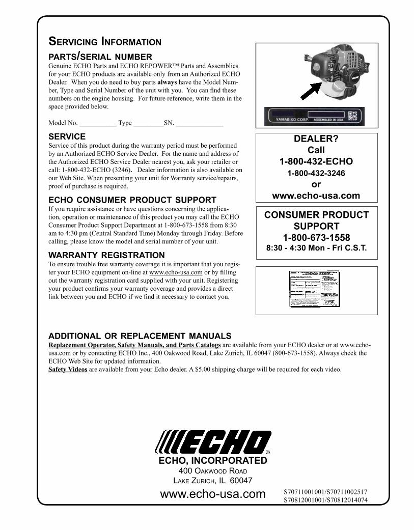
servIcIng InformatIonparts/serIal number Genuine ECHO Parts and ECHO REPOWER™ Parts and Assemblies for your ECHO products are available only from an Authorized ECHO Dealer. When you do need to buy parts always have the Model Num-ber, Type and Serial Number of the unit with you. You can find these numbers on the engine housing. For future reference, write them in the space provided below.
Model No. ___________ Type _________SN. ______________
servIceService of this product during the warranty period must be performed by an Authorized ECHO Service Dealer. For the name and address of the Authorized ECHO Service Dealer nearest you, ask your retailer or call: 1-800-432-ECHO (3246). Dealer information is also available on our Web Site. When presenting your unit for Warranty service/repairs, proof of purchase is required.
echo consumer product supportIf you require assistance or have questions concerning the applica-tion, operation or maintenance of this product you may call the ECHO Consumer Product Support Department at 1-800-673-1558 from 8:30 am to 4:30 pm (Central Standard Time) Monday through Friday. Before calling, please know the model and serial number of your unit.
warranty regIstratIon To ensure trouble free warranty coverage it is important that you regis-ter your ECHO equipment on-line at www.echo-usa.com or by filling out the warranty registration card supplied with your unit. Registering your product confirms your warranty coverage and provides a direct link between you and ECHO if we find it necessary to contact you.
addItIonal or replacement manuals Replacement Operator, safety Manuals, and Parts Catalogs are available from your ECHO dealer or at www.echo-usa.com or by contacting ECHO Inc., 400 Oakwood Road, Lake Zurich, IL 60047 (800-673-1558). Always check the ECHO Web Site for updated information.safety Videos are available from your Echo dealer. A $5.00 shipping charge will be required for each video.