Embed Size (px)
Citation preview
BEATTY ENERGY CENTER PROJECT DESCRIPTION
MAY 2021
PREPARED FOR
Boulevard Associates, LLC
A Subsidiary of NextEra Energy
Resources, LLC
PREPARED BY
SWCA Environmental Consultants

BEATTY ENERGY CENTER PROJECT DESCRIPTION
Prepared for
Boulevard Associates, LLC A Subsidiary of NextEra Energy Resources, LLC
700 Universe Boulevard Juno Beach, Florida 33408 Attn: Kathleen Campanella
Prepared by
SWCA Environmental Consultants 7210 Placid Street
Las Vegas, NV 89119 (702) 248-3880 www.swca.com
For Submittal to:
Bureau of Land Management Tonopah Field Office
1553 South Main Street P.O. Box 911
Tonopah, NV 89049
May 2021

Beatty Energy Center Project
i
CONTENTS
Name and Address of Applicant ................................................................................................................ 1
Proposed Project Description .................................................................................................................... 1
Plan of Development (POD) Schedule ....................................................................................................... 1
Technical and Financial Capability........................................................................................................... 1
Proposed Project Location ......................................................................................................................... 3
Proposed Project Setting ............................................................................................................................ 3
Alternatives .................................................................................................................................................. 4
Authorizations and Pending Applications ................................................................................................ 4
Project Need ................................................................................................................................................ 4
Proposed Project Characteristics .............................................................................................................. 4
Solar Energy Generation System ............................................................................................................ 4
On-Site Substation, Switching Station, and Generation Tie-In Line...................................................... 5
Energy Storage System .......................................................................................................................... 5
Ancillary Facilities ................................................................................................................................. 6 Access Road ..................................................................................................................................... 6 Signage ............................................................................................................................................. 6 Perimeter and Substation Fence ....................................................................................................... 6 Lighting ............................................................................................................................................ 7
Construction ................................................................................................................................................ 7
Schedule ................................................................................................................................................. 7
Traffic ..................................................................................................................................................... 7
Construction Activities ........................................................................................................................... 8
Water Use ............................................................................................................................................... 8
On-Site Eletrical Distribution .................................................................................................................... 8
Operation ..................................................................................................................................................... 8
Decommissioning......................................................................................................................................... 8
Environmental and Human Effects ........................................................................................................... 9
References Cited/Literature Cited .......................................................................................................... 10
Figures
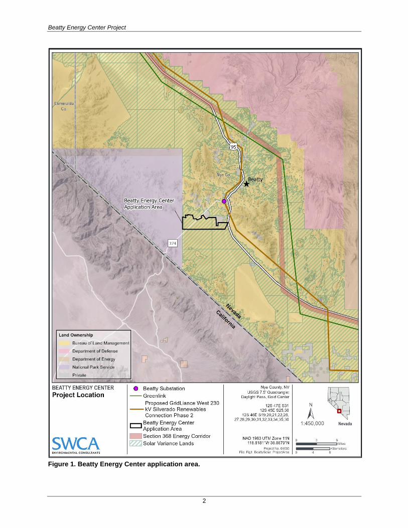
Figure 1. Beatty Energy Center application area. ......................................................................................... 2

Beatty Energy Center Project
ii
This page intentionally left blank.
Beatty Energy Center Project
1
NAME AND ADDRESS OF APPLICANT
Boulevard Associates, LLC
700 Universe Boulevard
Juno Beach, Florida 33408
Authorized Agent: Kathleen Campanella
Phone: (561) 694-3854
Email: [email protected]
PROPOSED PROJECT DESCRIPTION
Boulevard Associates, LLC (“Applicant”) is proposing to construct, operate, maintain, and decommission
an approximately 800-megawatt (“MW”) alternating current (“AC”) solar photovoltaic (“Solar PV”)
facility and energy storage project (the Beatty Energy Center Project [“Proposed Project”]) on
approximately 6,515 acres of public lands in Nye County, Nevada which are administered by the Bureau
of Land Management (“BLM”) Tonopah Field Office (Figure 1). An approximately 2-mile-long 138 or
230 kilovolt (kV) generation tie-in (gen-tie) line would extend from an on-site project substation through
BLM and private land to the Valley Electric Association (VEA) Beatty substation. Gen-tie line alignment
options are currently under development. The Applicant will pursue issuance of a Title V Federal Lands
Policy and Management Act of 1976 right-of-way (“ROW”) from the BLM for a 30-year term. In
addition to the solar facility, the Proposed Project would include inverters, perimeter fencing, roads, and a
supervisory control and data acquisition (“SCADA”) system.
PLAN OF DEVELOPMENT (POD) SCHEDULE
The Applicant is currently preparing a POD per the BLM POD template and will submit the POD to the
BLM Tonopah Field Office following the pre-application meeting.
TECHNICAL AND FINANCIAL CAPABILITY
Boulevard Associates, LLC is a subsidiary of NextEra Energy Resources LLC (NEER), a wholly-owned
subsidiary of NextEra Energy Capital Holdings Inc., who owns, develops, constructs, manages, and
operates primarily domestic electric-generating facilities that sell power into the wholesale energy
markets. NEER is an operator and owner of over 20,000 megawatts (MW) of energy facilities in North
America. As of 2019 NEER has 2,300 MW of solar facilities currently in operation including Mountain
View Solar (20 MW) and Silver State South Solar (250 MW) located in Clark County, Nevada. NEER is
currently building the 200 MW Dodge Flat Solar and 100 MW Fish Springs Solar projects in Washoe
County, Nevada with end of 2021 operation dates.
Beatty Energy Center Project
2
Figure 1. Beatty Energy Center application area.
Beatty Energy Center Project
3
PROPOSED PROJECT LOCATION
The Proposed Project would be on BLM land that is identified as variance lands in the Final Solar
Energy Development Programmatic Environmental Impact Statement (BLM 2012), as shown on
Figure 1. Lands identified as BLM exclusion lands would not be utilized.
The Proposed Project is found on Daylight Pass, and Gold Center, Nevada, U.S. Geological Survey
7.5- topographic quadrangles. The Project site is located on the north and south side of Highway 374,
approximately 2.6 miles southwest of the Town of Beatty, Nevada, and west of U.S. Route 95. The
legal land description for the solar facility that is on BLM-administered public lands is as follows.
Solar Facility:
Nye County, Beatty, Nevada, Mount Diablo, Meridian Nevada
T. 12 S., R. 45 E.,
sec 25, E ½ SE ¼, and E ½ NE ½;
sec 36, E ½ SE ¼, and E ½ NE ½.
T. 12 S., R. 46 E.,
sec 19, S ½ SE ¼, and SE ¼ SW ¼;
sec 20, SW ¼ SE ¼, and S ½ SW ¼;
sec 21, SE ¼ SE ¼;
sec 22, Lot 10;
sec 26,
sec 27, Lot 1 thru 6, SW ¼ NW ¼, and S ½;
sec 28, S ½, SW ¼ NW ¼, and NE ¼;
sec 29, S ½, NW ¼, NW ¼ NE ¼, and S ½ NE ¼;
sec 30,
sec 31,
sec 32,
sec 33,
sec 34,
sec 35,
sec 36.
T. 12 S., R. 47 E.,
sec 31, Lot 1 thru 4, E ½ NW ¼, E ½ SW ¼, and W ½ NE ¼.
PROPOSED PROJECT SETTING
The location of the Proposed Project has been selected because it provides a large, flat portion of land
suitable for solar development near the proposed VEA Beatty Substation. Using the BLM Solar Energy
Environmental Mapper (https://bogi.evs.anl.gov/solmap/portal/), the land is identified as available solar
variance land with strong solar potential (BLM 2012). There is also a BLM Section 368 corridor
approximately 7.5 miles to the east of the site.
Beatty Energy Center Project
4
ALTERNATIVES
Boulevard evaluated other private and BLM land with similar potential for interconnection; however,
other nearby BLM land is identified as exclusion and other potential sites would have required
substantially longer gen-tie lines which add environmental impact and cost. Further, there are not large
enough private parcels available near the interconnection point to facilitate a project of this size.
AUTHORIZATIONS AND PENDING APPLICATIONS
• Silver State South Solar: Case File N-85801
• Mountain View Solar: Case File N-90989
• Dodge Flat Solar: Case File N-96241. See DOI-BLM-NV-C020-2019-0017-EA
• Fish Springs Solar: Case File NVN-98157. See DOI-BLM-NV-C020-2020-0012
• Yellow Pine Solar: Case File N 90788. See DOI- BLM-NV-S010-2017-0110-EIS
• Mason Valley Solar: NVN-100105
• Pine Nut Solar: NVN-100106
• Dodge Flat II Solar: NVN-100104
PROJECT NEED
The project would deliver renewable energy into the Nevada energy grid and support the state's RPS goal
(50% by 2030).
PROPOSED PROJECT CHARACTERISTICS
The Proposed Project consists of the following components:
• PV solar energy generation system
• On-site substation, switching station, and 138 or 230 kV gen-tie line
• Energy storage system
• Ancillary facilities
Solar Energy Generation System
The Proposed Project includes an approximately 800-MW nameplate capacity solar power–generating
installation built over an approximate 36 to 48-month period. The existing site would house all structures,
including solar panels, tracking/support structures, inverters, SCADA system, energy storage facilities,
and interconnection facilities (i.e., possible on-site substation and/or switching station), all of which
would be enclosed by a perimeter security fence. Solar energy would be captured by an array of panels
mounted to a single-axis tracking system (the final number of panels will be determined based on the
selected panel manufacturer and size of the panel selected).
Beatty Energy Center Project
5
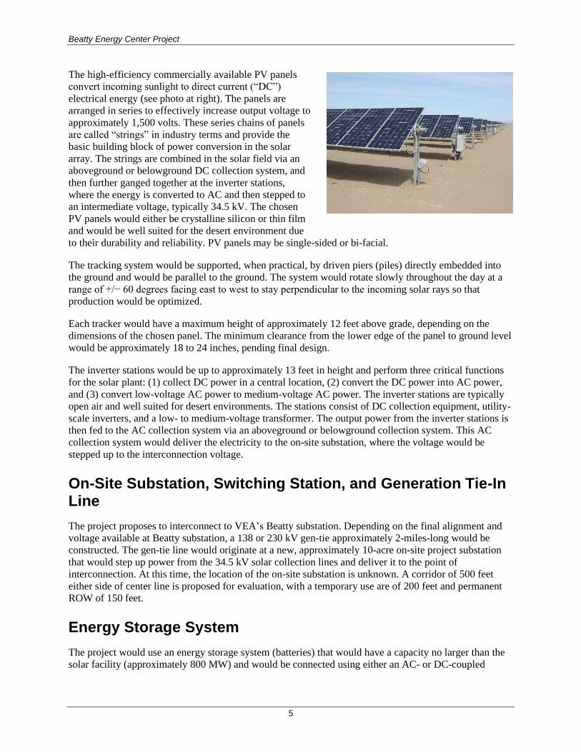
The high-efficiency commercially available PV panels
convert incoming sunlight to direct current (“DC”)
electrical energy (see photo at right). The panels are
arranged in series to effectively increase output voltage to
approximately 1,500 volts. These series chains of panels
are called “strings” in industry terms and provide the
basic building block of power conversion in the solar
array. The strings are combined in the solar field via an
aboveground or belowground DC collection system, and
then further ganged together at the inverter stations,
where the energy is converted to AC and then stepped to
an intermediate voltage, typically 34.5 kV. The chosen
PV panels would either be crystalline silicon or thin film
and would be well suited for the desert environment due
to their durability and reliability. PV panels may be single-sided or bi-facial.
The tracking system would be supported, when practical, by driven piers (piles) directly embedded into
the ground and would be parallel to the ground. The system would rotate slowly throughout the day at a
range of +/− 60 degrees facing east to west to stay perpendicular to the incoming solar rays so that
production would be optimized.
Each tracker would have a maximum height of approximately 12 feet above grade, depending on the
dimensions of the chosen panel. The minimum clearance from the lower edge of the panel to ground level
would be approximately 18 to 24 inches, pending final design.
The inverter stations would be up to approximately 13 feet in height and perform three critical functions
for the solar plant: (1) collect DC power in a central location, (2) convert the DC power into AC power,
and (3) convert low-voltage AC power to medium-voltage AC power. The inverter stations are typically
open air and well suited for desert environments. The stations consist of DC collection equipment, utility-
scale inverters, and a low- to medium-voltage transformer. The output power from the inverter stations is
then fed to the AC collection system via an aboveground or belowground collection system. This AC
collection system would deliver the electricity to the on-site substation, where the voltage would be
stepped up to the interconnection voltage.
On-Site Substation, Switching Station, and Generation Tie-In Line
The project proposes to interconnect to VEA’s Beatty substation. Depending on the final alignment and
voltage available at Beatty substation, a 138 or 230 kV gen-tie approximately 2-miles-long would be
constructed. The gen-tie line would originate at a new, approximately 10-acre on-site project substation
that would step up power from the 34.5 kV solar collection lines and deliver it to the point of
interconnection. At this time, the location of the on-site substation is unknown. A corridor of 500 feet
either side of center line is proposed for evaluation, with a temporary use are of 200 feet and permanent
ROW of 150 feet.
Energy Storage System
The project would use an energy storage system (batteries) that would have a capacity no larger than the
solar facility (approximately 800 MW) and would be connected using either an AC- or DC-coupled
Beatty Energy Center Project
6
system. Selection of an AC- or DC-coupled system is ultimately determined through off-taker preference
and contract terms.
The AC-coupled system would be connected to a bi-directional inverter to convert DC energy to
AC energy, allowing for energy to flow in or out of the batteries in order to provide charge and discharge.
This AC energy would be coupled to the PV array at the 34.5-kV busbars. Power switches and relays
would protect the system. The system would consist of several housing units, similar to shipping
containers. The containers would be placed on concrete pads and would occupy up to 50 acres, depending
on the size of the system contracted and technology selected. The equipment enclosures and buildings
would be located next to the Project Substation and operations and maintenance building.
If a DC-coupled system is used, battery units would be stored in numerous smaller containers. Those
containers would make use of the solar inverters, feeding them in DC power. Therefore, the battery
containers would be distributed throughout the solar arrays, adjacent to their respective inverters. The
containers would be similar in size (20–40 feet long) to the solar inverter skids. The battery and solar inputs
would be metered separately prior to signal inversion. The charge and discharge of the DC-coupled batteries
would be controlled by signal from the inverters. As is typical for the industry, inverters would be controlled
by a central control system. The protections to the batteries would be internal to the battery management
systems and control boxes located within the containers and inverters.
A battery supplier has not been selected at this time due to changing markets; however, past suppliers have
included LG Chem, Samsung, BMW, Tesla, and Lishen. Inverter suppliers would likely include ABB, Parker
Hannifin, S&C Electric, Eaton, Princeton Power, DynaPower, Power Electronics, and Ideal Power. The final
battery supplier(s) would be selected prior to project construction and would be subject to an industry-standard
pre-qualification process.
Ancillary Facilities
Access Road
Primary access to the Project would be from U.S. Route 95 and Highway 374 which is accessed from
U.S. Route 95 in the Town of Beatty. Primary Proposed Project access road(s) would typically be 24 feet
wide and composed of either 6 inches of type II class B aggregate base compacted to 95% maximum dry
density or asphalt concrete.
Internal access roads to the on-site substation, switching station, and energy storage system would consist
of 20-foot-wide roads with compacted gravel or dirt. Internal maintenance pathways between solar
modules would be approximately 16 feet wide.
Signage
A small sign would be installed at the site’s main entry to the Proposed Project. The sign would be no
larger than 8 feet by 4 feet and would read “Beatty Energy Center.” In addition, required safety signs
would be installed identifying high voltage within the facility on the fence near the entrance, as well as
information for emergency services.
Perimeter and Substation Fence
The perimeter of the Project Site would be enclosed by a 6-foot-tall chain-link fence topped with a foot of
three-strand barbed wire. Access into the Project Site would be provided through drive-through gates. The
main purpose of the fence would be to prevent unauthorized access to the site. The total height, above
Beatty Energy Center Project
7
grade, of the fence would be approximately 7 feet. The perimeter around the proposed substation would
be enclosed by a 7-foot-tall chain-link fence, topped with a foot of three-strand barbed wire. Cattle guards
would be installed with gates as necessary.
Lighting
Low-elevation (< 14-foot) controlled security lighting would be installed at primary access gates, the on-
site substation, and the entrance to the energy storage structure(s). The lighting is only switched on when
personnel enter the area (either motion-sensor or manual activation [switch]). All safety and emergency
service signs would be lit when the lights are on. The lighting would be shielded so that the light is
directed downwards. Electrical power to supply the access gate and lighting would be obtained from the
local electricity provider. Lighting would only be in areas where it is required for safety, security, or
operations. All lighting would be directed on site and would include shielding as necessary to minimize
illumination of the night sky or potential impacts to surrounding viewers.
CONSTRUCTION
Schedule
The Proposed Project is intended to be constructed in a single phase; however, it may be developed in
multiple phases depending on final power purchase agreements. The total construction duration assuming
a single phase is planned to take approximately 36 to 48 months from notice to proceed to final
connection and commissioning. If multiple phases are constructed, total construction length would be
extended. It is anticipated that the work would be completed in 8- to 10-hour shifts, with a total of five
shifts per week (Monday–Friday). Overtime and weekend work would be used only as necessary to meet
scheduled milestones or accelerate schedule and would comply with all applicable Nevada labor laws.
Traffic
For an 800-MW project, the peak daily construction employees would be approximately 600 daily. In
addition to the approximately 600 maximum daily workers traveling to the site, there would be up to
approximately 35 truck trips per day at peak construction activity (when trenching and system installation
phases overlap). A total of up to 625 trips per day are anticipated during peak construction activities,
assuming a worst-case scenario whereby no carpooling occurs, though it is likely that carpooling would
occur.
Delivery of materials and supplies would reach the site via on-road truck delivery via U.S. Route 95,
Highway 374, and the Project access road. The majority of the truck deliveries would be for the PV
system installation and any aggregate material that may be required for road base.
The heaviest delivery loads to the site would consist of the tracker structures, rock truck deliveries, and
the generator step up. These loads would typically be limited to a total weight of 80,000 pounds, with a
cargo load of approximately 25 tons or 50,000 pounds of rock or tracker structures. The generator step up
could be up to 160,000 pounds. Typically, the rock is delivered in “bottom dump trucks” or “transfer
trucks” with six axles and the tracker structures would be delivered on traditional flatbed trucks with a
minimum of five axles. Low-bed transport trucks would transport the construction equipment to the site
as needed. The size of the low-bed truck (number of axles for weight distribution) would depend on the
equipment transported.

Beatty Energy Center Project
8
Construction Activities
Prior to initiation of grading operations, the construction areas will be cleared and grubbed of vegetation
and miscellaneous debris. The primary grading activities will be associated with the development of
access roads, with lesser quantities associated with the Project substation, and the associated foundations.
For these areas, grading will consist of the excavation and compaction of earth to meet the design
requirements. Grading within the solar field will match existing grades as close as possible. The existing
contours will need to be smoothed out to remove existing washes for access purposes.
Water Use
Water consumption during construction would be utilized for dust suppression and earthwork over an
approximately 36 to 48-month period. Panel rinsing is expected to be conducted up to four times annually
as performance testing and weather and site conditions dictate. Construction water and operational water
would either come from drilling a well on site or trucking in water from a nearby source.
ON-SITE ELETRICAL DISTRIBUTION
A distribution line to the project substation would be needed to provide construction power and backup
power to the solar and energy storage facilities for lighting and communications purposes, as well as to
the groundwater well pumps if needed. It is anticipated that would come from the existing line that
traverses the area. Alternatively, generators could be used to provide construction and backup power.
OPERATION
The Proposed Project would be unmanned, and no operations and maintenance building would be
constructed. Operations would be monitored remotely via the SCADA system, and periodic inspections
and maintenance activities would occur. During operations, solar panel washing is not expected to be
needed, but would not occur more than one to four times per year. Conditions that may necessitate
increased wash requirements include unusual weather occurrences, forest fires, local air pollutants, and
other similar conditions. A general labor force (up to 30 individuals) may assist in the panel cleaning.
Panel washing for a project of this size would require approximately 40 days to complete per wash cycle.
If groundwater proves unsuitable for washing, water trucks would be used to deliver water from a local
purveyor.
DECOMMISSIONING
The PV system and energy storage system (including structure) would be recycled when the Proposed
Project’s life is over. Most parts of the proposed system are recyclable. Panels typically consist of silicon,
glass, and a metal frame. Batteries include lithium-ion, which degrades but can be recycled and/or
repurposed. Site structures would include steel or wood and concrete. All of these materials can be
recycled. Concrete from deconstruction is to be recycled. Local recyclers are available. Metal and scrap
equipment and parts that do not have free-flowing oil may be sent for salvage.
Fuel, hydraulic fluids, and oils would be transferred directly to a tanker truck from the respective tanks
and vessels. Storage tanks/vessels would be rinsed and transferred to tanker trucks. Other items that are
not feasible to remove at the point of generation, such as smaller containers, lubricants, paints, thinners,

Beatty Energy Center Project
9
solvents, cleaners, batteries, and sealants, would be kept in a locked utility building with integral
secondary containment that meets Certified Unified Program Agencies and Resource Conservation and
Recovery Act requirements for hazardous waste storage until removal for proper disposal and recycling.
It is anticipated that all oils and batteries would be recycled at an appropriate facility. Site personnel
involved in handling these materials would be trained to properly handle them. Containers used to store
hazardous materials would be inspected regularly for any signs of failure or leakage. Additional
procedures would be specified in the hazardous materials business plan. Transportation of the removed
hazardous materials would comply with regulations for transporting hazardous materials, including those
set by the U.S. Department of Transportation, Nevada Department of Transportation, U.S. Environmental
Protection Agency, Nevada Highway Patrol, and Nevada State Fire Marshal.
Upon removal of the Proposed Project components, the site would be left as disturbed dirt generally
consistent with the existing (pre-development) conditions.
ENVIRONMENTAL AND HUMAN EFFECTS
The project is located in a rural area approximately 2.6 miles away from the Town of Beatty. The project
is not anticipated to have any substantial effects on air quality, visual resources, water resources, noise,
vegetation, soils, wildlife, or historic/archaeological resources/properties. No hazardous materials are
expected to be used, produced, transported, or stored on or within the ROW; however, further analysis
will be completed in the POD and NEPA process. Grazing allotments are within the project vicinity and
early coordination with active permittees will occur in accordance with BLM regulation 43 CFR 4110.4-
2(b).

Beatty Energy Center Project
10
REFERENCES CITED/LITERATURE CITED
BLM (U.S. Bureau of Land Management). 2012. Final Solar Energy Development Programmatic
Environmental Impact Statement for Solar Energy Development in Six Southwestern
States. July 2012. https://www.energy.gov/nepa/downloads/eis-0403-final-programmatic-
environmental-impact-statement.