Embed Size (px)
DESCRIPTION
Bearings - Types, Calculations & Applications
Citation preview

1
Rolling Contact Bearings – load is transferred through rolling elements such as balls, straight and tapered cylinders and spherical rollers.
Journal (sleeve) Bearings – load is transferred through a thin film of lubricant (oil).

Rolling Contact BearingsLoad is transferred through elements in rolling contact
rather than sliding contact.
2

3
Journal (Sleeve) Bearings
Load is transferred through a lubricant in sliding contact

4
Thick-film lubrication (hydrodynamic), pressure distribution, and film thickness.
hmin = minimum film thickness, c = radial clearance, e = eccentricity

Bearing life and reliability Bearing speed (rpm) Space limitation Accuracy
5
• Bearing load – radial, thrust (axial) or both
Radial loadRadial load
Thrust load
Bearings are selected from catalogs, before referring to catalogs you should know the followings:

Deep groove (Conrad) bearing Filling notch ball bearing or maximum capacity
bearing Angular contact bearings (AC)
6
1. Ball bearings
3. Thrust bearings
4. Linear bearings
• Cylindrical bearings
• Needle bearings
• Tapered bearings
• Spherical bearings
2. Roller bearings

7
1. Deep groove (Conrad) bearing
• Primarily designed to support radial loads, the thrust capacity is about 70% of radial load capacity
• Load capacity is limited by the number of balls

8
2. Filling notch or maximum capacity ball bearingsBearings have the same basic radial construction as Conrad type. However, a filling notch (loading groove) permits more balls to be used.
• Thrust load capacity drops to 20% (2 directions) of radial load capacity.
Notch
• Radial load capacity is 20 – 40% higher than Conrad type
9
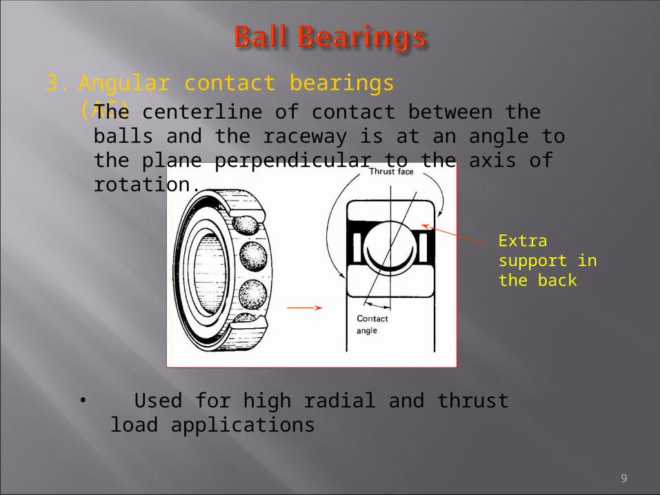
3. Angular contact bearings (AC)The centerline of contact between the balls and the raceway is at an angle to the plane perpendicular to the axis of rotation.
• Used for high radial and thrust load applications
Extra support in the back
Direction of thrust

10
Roller bearings have higher load capacity than ball bearings, load is transmitted through line contact instead of point contact.
Straight cylindrical roller Needle type

11
Tapered bearingsDesigned to withstand high radial loads, high thrust loads, and combined loads at moderate to high speeds. They can also withstand repeated shock loads.

12
Indirect and Direct mounting
Indirect mounting
Direct mounting
Indirect mounting provides greater rigidity when pair of bearings is closely spaced: front wheel of a car, drums, sheaves,..
Direct mounting provides greater rigidity when pair of bearings is not closely spaced: transmission, speed reducers, rollers,..
aa = effective bearing spread
Measure of the rigidity of the bearing mounting

13
Spherical bearings
Bearing design uses barrel shaped rollers. Spherical roller bearings combine very high radial load capacity with modest thrust load capacity and excellent tolerance to misalignment.

14
Ball thrust bearing Roller thrust bearing

15
Spherical Thrust Bearings
Cylindrical Thrust Bearings
Tapered Thrust Bearings

16

17
Load runners (idler-rollers)
Roller bearing cam follower
Flanged V-Grooved
Spherical rod end

18
Airframe control bearings – designed to meet the specific needs of the airframe industry, meets military and national standards.
Designed to carry heavy static load and will also handle oscillation or slow rotation.
Track rollers, withstand heavy rolling loads.

19

20

21
Pillow Block Flange
Common mounting, inner ring held in position by nuts threaded onto the shaft.
Alternative method, inner ring is press fitted onto the shaft.
Two-bearing mounting

Comparison of Ball Bearings
22

Bearing Comparison
23
24
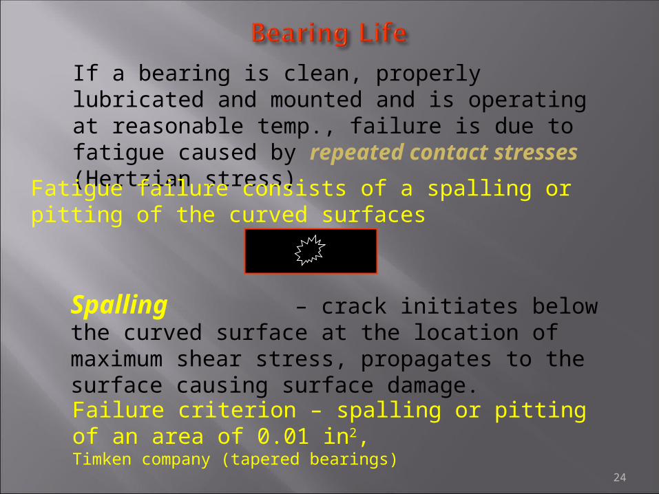
If a bearing is clean, properly lubricated and mounted and is operating at reasonable temp., failure is due to fatigue caused by repeated contact stresses (Hertzian stress)
Fatigue failure consists of a spalling or pitting of the curved surfaces
Failure criterion – spalling or pitting of an area of 0.01 in2, Timken company (tapered bearings)
– crack initiates below the curved surface at the location of maximum shear stress, propagates to the surface causing surface damage.
Spalling

25
Life – number of revolution or hours of operation, at constant speed, required for the failure criterion to develop.
L10 = 500 (hours) x 33.33 (rpm) x 60 = 106 = 1 million revolutions
For ball bearings and spherical bearings:
For tapered bearings manufactured by Timken:
L10 = 3000 (hours) x 500 (rpm) x 60 = 90 x 106 = 90 million revolutions
– defines the number of revolution or hours of operation, at constant speed, in such a way that of the bearings tested (from the same group) will complete or exceed before the first evidence of failure develops. This is known as life.
Rating Life
L10
90%
– constant radial load that a group of bearings can carry for L10 life.Basic Dynamic Load Rating, C
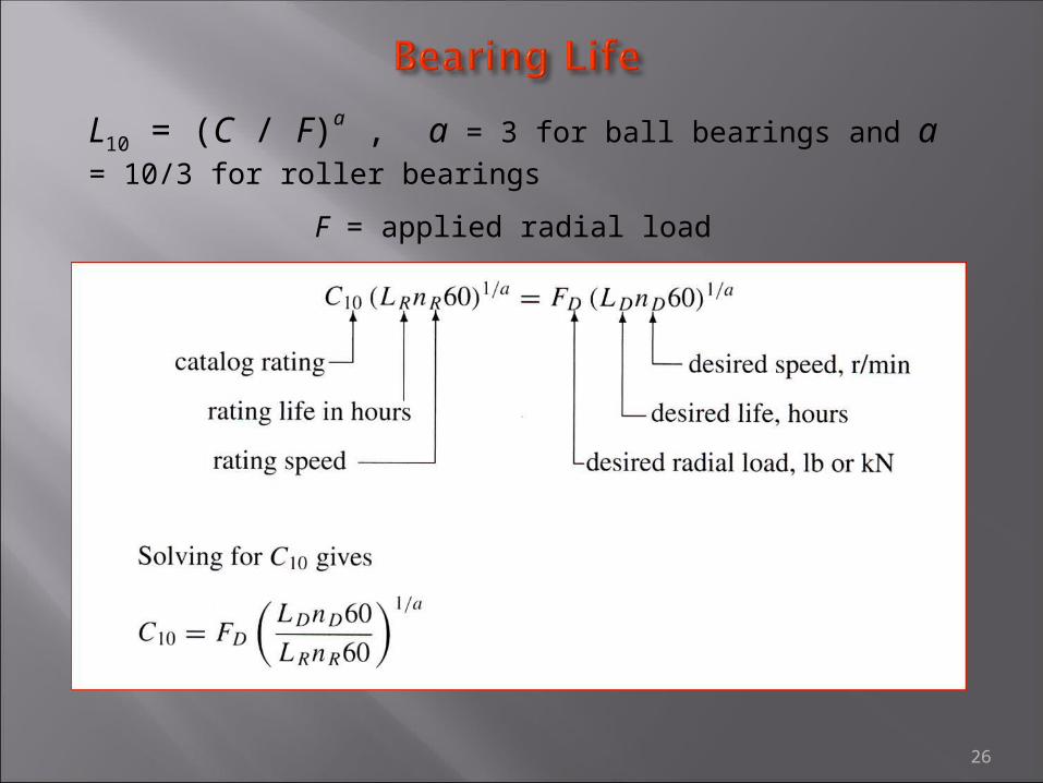
26
L10 = (C / F)a , a = 3 for ball bearings and a = 10/3 for roller bearings
F = applied radial load
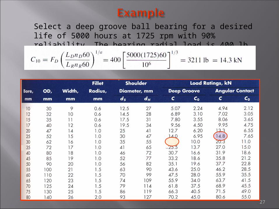
27
Select a deep groove ball bearing for a desired life of 5000 hours at 1725 rpm with 90% reliability. The bearing radial load is 400 lb.

28
If a machine is assembled with 4 bearings, each having a reliability of 90%, then the reliability of the system is (.9)4 = .65 = 65%. This points out the need to select bearings with higher than 90% reliability.
The distribution of bearing failure can be best approximated by two and three parameter Weibull distribution.
Two parameter Weibull distribution for tapered bearings
C10
C10 is the catalog basic dynamic load rating corresponding to LR hours of life at the speed of nR rpm.
C10

29
Select a deep groove ball bearing for a desired life of 5000 hours at 1725 rpm with 99% reliability. The bearing radial load is 400 lb.
C10 = 14.3 kN 30 mm Bore deep groove bearing
For 90% reliability
Use 99% reliability, R = .99
= 23.7 kN
Select a 35 mm bearing instead of 30 mm for 90% reliability
Lnew D = LD / .22 = 5000 / .22 = 22,770 hours
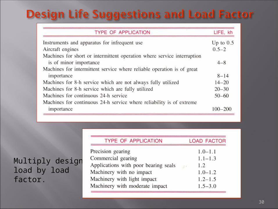
30
Multiply design load by load factor.

31
Bearings are usually operated with some combination of radial and thrust load. Catalog ratings are based only on radial loads. Follow the guideline in catalogs to obtain the equivalent radial load.

32
P = XVFr + YFa
P = equivalent load
Fr = applied radial load (constant)
Fa = applied thrust load (constant)
X = radial factor
Y = thrust factor
V = rotational factor
Specified by bearing manufacturer

33