Embed Size (px)
Citation preview
BEARING CAPACITY OF MODEL FOOTINGS ON
SAND
A PROJECT SUBMITTED IN PARTIAL FULFILLMENT
OF THE REQUIREMENTS FOR THE DEGREE OF
By K.R.Srivatsan
& Satyabrata behera
Bachelor of Technology
In CIVIL Engineering
Department of Civil Engineering
National Institute of Technology
Rourkela
2007

BEARING CAPACITY OF MODEL FOOTINGS ON
SAND
A PROJECT SUBMITTED IN PARTIAL FULFILLMENT
OF THE REQUIREMENTS FOR THE DEGREE OF
Bachelor of Technology
In Civil Engineering
By
K.R.Srivatsan &
Satyabrata Behera
Under the guidance of Prof. N.R.Mohanty
Department of Civil Engineering
National Institute of Technology
Rourkela
2007

National Institute of Technology
Rourkela
CERTIFICATE
This is to certify that the project entitled “Bearing capacity of model footings on
sand’’ submitted by K.R.Srivatsan, Roll No: 10301032 and Satyabrata Behera, Roll No:
10301009 in the partial fulfillment of the requirement for the award of Bachelor of
Technology in Civil Engineering, National Institute of Technology, Rourkela, is being carried
out under my supervision.
To the best of my knowledge the matter embodied in the project has not been submitted
to any other university/institute for the award of any degree or diploma.
Prof. N.R.Mohanty
Department of Civil Engineering
National Institute of Technology
Date: Rourkela.
Acknowledgment
We avail this opportunity to extend our hearty indebtedness to our guide
Dr. N.R.Mohanty, Professor ,Department of Civil Engineering, NIT Rourkela, for his
valuable guidance, constant encouragement and kind help at different stages for the execution
of this project work.
We also express our sincere gratitude to Dr. K.C.Patra, Head of the Department, civil
Engineering, for providing valuable departmental facilities. We also express our gratitude to
all the faculty and staff members of civil Engineering Department for extending their help in
completing this project.
Submitted by:
K.R.Srivatsan
Roll No: 10301032,
Satyabrata Behera,
Roll No: 10301009
Department of Civil Engineering, National Institute of Technology,

CONTENTS
Sl no. TOPIC Page no. I CONTENT i II ABSTRACT ii III LIST OF FIGURES iii IV LIST OF TABLES iv 1 Definitions
1
2 Methods of finding out bearing capacity:
4
3 Test On Model Footing
6
4 Building Code Method
12
4 Terzaghi Analysis
15
5 Meyerhor Analysis
20
6 Cohesive Soil (i)cohesive soil and non-cohesive soil
24
8 Bearing Capacity Of Model Footings On Sand
26
9 Direct Shear Test
31
10 Conclusion
38
11 Reference
38
i
ABSTRACT Soil mechanics engineering is one of most important aspects of civil
engineering involving the study of soil , its behaviour and application as an engineering
material.good soil engineering embodies the use of the best practices in exploration,testing
,design and construction control,in addition to the basic idealized theories. with increasing
load on soil due to construction of multi storeyed buildings there is a need to construct
footing by conducting a test of their model in laboratory on the soil over which the
foundation is to be laid.
Sand is one of the soils over which foundations are laid ,so it is necessary to
conduct experiments by placing different model footings over sand and find out their
ultimate bearing capacity and based on these values ,it can be incorporated on to the field
and foundations can be laid. Square footings of different sizes are taken and model testing of
these footings are conducted and the ultimate bearing capacity of different footings are found
and on the basis of these values foundations are laid on sandy soils .these values can also be
compared with theoretical analysis of Terzaghi and Meyerhof ‘s to check out the difference in
values of ultimate bearing capacity between a theoretical and practical analysis.
ii
LIST OF FIGURES:
FIGURE NO. NAME PAGE
Figure 3.1 Experimental Setup Of Plate Load Test
8
Figure 3.3 Experimental Setup Of Plate Load Test
8
Figure 3.3 Experimental Setup Of Plate Load Test
9
Figure 5.1 Shallow Foundation
16
Figure 5.2 Zones Of Plastic Equlibrium
17
Figure 6.1 Shallow Foundation
21
Figure 6.2 Deep Foundation
22
Figure 8.1 Load Intensity Vs Settlement Curve
28
Figure 8.2 Load Intensity Vs Settlement Curve
29
Figure 8.3 Load Intensity Vs Settlement Curve
30
Figure 9.1 Normal Stress Vs Shear Stress
33
iii

LIST OF TABLES
TABLE NO:
NAME PAGE NUMBER
4.1 Allowable Soil Pressures For Various Locations As Per
Building Code
14
5.1 Terzaghi’s Bearing Capacity Factors 19
6.1 Meyerhof’s Bearing Capacity Factors 23
6.2 Shape, Depth And Inclination Factors For The Meyerhof’s
Equation
23
8.1 Pressure Intensity Vs Settlement Characteristics Of Square
Footing
28
8.2 Pressure Intensity Vs Settlement Characteristics Of Square
Footing
29
8.3 Pressure Intensity Vs Settlement Characteristics Of Square
Footing
30
9.1 Angle Of Internal Friction 33
9.2 Comparison Of Bearing Capacities Between Theoretical And
Practical Analysis
35
9.3 Comparison Of Bearing Capacities Between Theoretical And
Practical Analysis
36
9.4 Comparison Of Bearing Capacities Between Theoretical And
Practical Analysis
37
iv
CHAPTER 1
DEFINITIONS
1

1. Definitions: Bearing capacity:- The supporting power of a soil or rock id referred to as its bearing capacity.
The term bearing capacity is defined after attaching certain qualifying prefixes, as defined
below.
Gross pressure intensity (q): The gross pressure intensity q is the total pressure at the base of the footing
due to the weight of the superstructure, self-weight of the footing and the weight of the earth
fill, if any.
Net pressure intensity (qn): It is defined as the excess pressure , or the difference in intensities of the
structure and the original overburden pressure. The construction of the structure and the
effective overburden pressure. if, D is the depth of the footing
dqqn γ−=
=γ Average unit weight of soil above the foundation base.
Ultimate bearing capacity (qf):
The ultimate bearing capacity is defined as the minimum gross
pressure intensity at the base of the foundation at which the soil fails in shear.
Net ultimate bearing capacity (qnf): It is the minimum net pressure intensity causing shear failure of the soil. the
ultimate bearing capacity qf and the net ultimate bearing capacity are
connected by the following relation :
−+= σnff qq
Net safe bearing capacity (qns): The net safe bearing capacity is the net ultimate bearing capacity divided
by the factor of safety F
f
qq nf
ns =
2
Safe bearing capacity (qs):
the maximum pressure which the soil can carry without risk of shear failure
is called the safe bearing capacity .it is equal to the net safe bearing capacity plus original
overburden pressure:
df
qq nf
s γ+=
Sometimes the safe bearing capacity is also referred as the ultimate bearing capacity divided
by a factor of safety f.
3
CHAPTER 2
METHODS OF FINDING OUT BEARING CAPACITY
4
2. Methods of finding out bearing capacity: There are various methods to find out bearing capacity ,some of the methods are
1. Determination of building capacity by building code method
2. By plate load test
3. Theoritical analysis
Theoretical analysis is done by two methods, they are
1. Terzaghi’s analysis.
2. Meyerhof’s analysis
5

CHAPTER 3
TEST ON A MODEL FOOTING
6

3. Test on a model footing: The ultimate bearing capacity of a soil and the probable settlement
under a given loading is found out by testing the soil on various sizes of model footings.the
test essentially consists in loading a rigid plate at the foundation level and determining the
settlements corresponding at each load increment. the ultimate bearing capacity is then taken
as the load at which the plate starts sinking at a rapid rate .the method assumes that down to
the depth of influence of stresses ,the soil strata is reasonably uniform.
The bearing plate is square of minimum recommended size 30 cm square and maximum size
recommended is 75 cm square. the plate is machined on sides and edges and should have a
thickness sufficient to withstand effectively the bending stresses that would be caused by
maximum anticipated load. the thickness of steel plate should not be less than 25 mm.
the test pit width is made five times the width of the plate bp . at the centre of the pit, a small
square hole is dug whose size is equal to the size of the plate and the bottom level of which
correspond to the level of actual depth formation . the depth dp of the hole should be such
that
BD
widthfoundationdepthfoundation
bd
p
p ==[
3.1Plate load test: the loading to the test plate may be applied with the help of a hydraulic jack.
the reaction of the hydraulic jack may be borne either of the following two methods
1. Gravity loading platform method
2. Reaction truss method
7

fig no 3.2
8
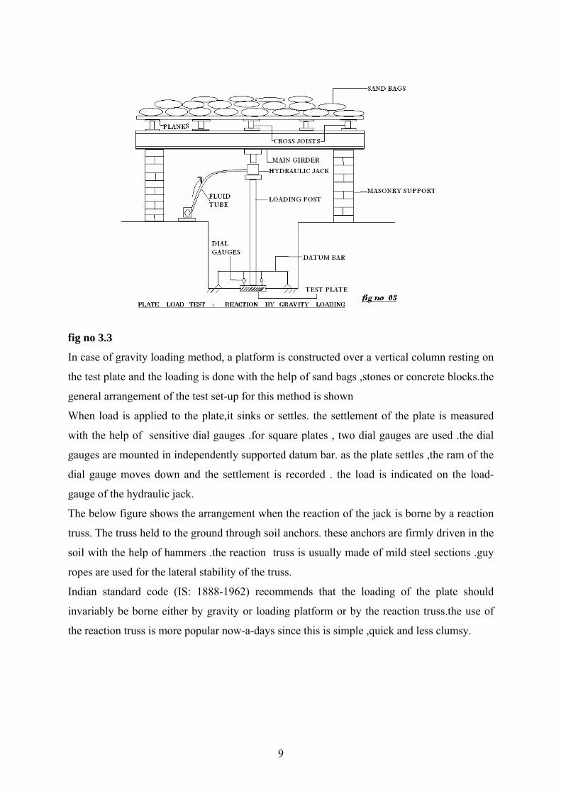
fig no 3.3
In case of gravity loading method, a platform is constructed over a vertical column resting on
the test plate and the loading is done with the help of sand bags ,stones or concrete blocks.the
general arrangement of the test set-up for this method is shown
When load is applied to the plate,it sinks or settles. the settlement of the plate is measured
with the help of sensitive dial gauges .for square plates , two dial gauges are used .the dial
gauges are mounted in independently supported datum bar. as the plate settles ,the ram of the
dial gauge moves down and the settlement is recorded . the load is indicated on the load-
gauge of the hydraulic jack.
The below figure shows the arrangement when the reaction of the jack is borne by a reaction
truss. The truss held to the ground through soil anchors. these anchors are firmly driven in the
soil with the help of hammers .the reaction truss is usually made of mild steel sections .guy
ropes are used for the lateral stability of the truss.
Indian standard code (IS: 1888-1962) recommends that the loading of the plate should
invariably be borne either by gravity or loading platform or by the reaction truss.the use of
the reaction truss is more popular now-a-days since this is simple ,quick and less clumsy.
9

3.2Test procedure: The plate is firmly seated in the hole and if the ground is slightly uneven,
a thin layer of sand is spread underneath the plate. Indian standard (IS:1888-1962)
recommends a seating load of 70 g\cm2 which is released before the actual test is started.the
load is applied with the help of a hydraulic jack in convenient increments, say of about one-
fifth of the expected safe bearing capacity or one-tenth of the ultimate bearing capacity.
settlement of the plate is observed by 2 dial gauges fixed at diametrically opposite ends,with
sensitivity of .02 mm .Settlement of the plate is observed for each increment of load after an
interval of 1,4,10,20,40 and 60 minutes and thereafter at hourly intervals until the rate of
settlement becomes less than about 0.02 mm per hour. After this,the next load increment is
applied. the maximum load that is to be applied corresponds to 121 times the estimated
ultimate load or to a 3 times the proposed allowable bearing pressure.
the water table has a marked influence on the bearing capacity of sandy or gravelly soil. if the
water table is already above the level of the footing, it should be lowered by pumping and the
bearing plate seated after the water table has been lowered just below the footing level.even if
the water table is located above 1 m below the base level of the footing ,the load test should
be made at the level of the water table itself.
The load intensity and settlement observation of the plate load test are plotted. curve 1
corresponds to general shear failure , curve 2 corresponds to local shear failure ,curve 3 is a
typical of dense cohesionless soils which do not show any marked sign of shear failure under
the loading intensities of the test. Is: 1888-1962 recommends a log-log plot giving two
straight lines the intersection of which may be considered the yield value of the soil.when a
load settlement curve does not indicate any marked breaking point failure may alternatively
be assumed corresponding equal to one-fifth of the width of the test plate .In order to
determine the safe bearing capacity it would be normally sufficient to use a factor of safety 2
or 2.5 on ultimate bearing capacity.
10
3.3 Limitations of plate load test: 1. the test reflects only the character of the soil located within a depth less than twice the
width of the bearing plate .since the foundations are generally larger the settlement and
resistance against shear failure will depend on the properties of a much thicker stratum.
2. it is essentially a short duration test , and hence the test does not give the ultimate
settlement ,particularly in case of cohesive soil.
3.another limitation is the effect of size of foundation .for clayey soils the ultimate pressure
for a large foundation is the same as that of the test plate .but in dense sandy soils the bearing
capacity increases with the size in foundation and the test on smaller size bearing plates tend
to give conservative values.
11
CHAPTER 4
BUILDING CODE METHOD
12

4. Building code method: Before the 19th century the framework for most of the buildings
consisted of strong but somewhat flexible main walls interconnected by massive but equally
flexible partition walls intersecting each other at right angles. since such buildings could
stand large settlements without damage ,their builders gave little considerations to
foundations other to increase the wall thickness of the base .the development of highly
competitive during the 19th century led to demand for large but inexpensive buildings. the
types that developed was more sensitive to differential settlement than their predecessors.
hence designers need found themselves in a need of more reliable procedures, applicable
under soil conditions, for proportioning the footings of a given building in such a manner that
they would all experience nearly the same settlement. to satisfy this need the concept of
”allowable soil pressure” was developed during the 1870’s in several different countries. the
concept was based on the obvious fact that under fairly similar soil conditions ,footings
transmitted pressures of high intensity to the subsoil generally settled more than those
transmitting pressures at low intensity .the pressure beneath the footings of all those footings
that showed signs of damage due to settlement were considered too great for the given soil
conditions.the values obtained for each type of soil for a given locality is given in the table
below of allowable soil pressures that was subsequently incorporated into the building code
governing construction in that locality.
The building codes do not offer any hint regarding the origin of the values,or explaining the
meaning of the term “allowable soil pressure” .these omissions have fostered the belief that
settlement will be uniform and of no consequence if the pressure on the soil beneath each
footing is equal to allowable soil pressure. the size of loaded area and the type of building are
considered immaterial. but because of various confusions the engineers assumed that wrong
allowable pressures have been selected because the terms used to describe the soil in the field
and the building codes did not have the same building . in order to avoid this difficulty ,it
gradually became customary to select the soil pressure on the basis of the results of load tests.
13

Character of Foundation bed(tn\ft ) 2
Akron 1920 Atlanta 1911 Boston 1926
Quick sand or alluvial soil
0.5 - -
Soft or wet clay, atleast 15 cm thick
1 1
Clay in thick beds 1
Hard clay 3-4 Clay in thick beds always dry
4
Rock 10 15 100
Gravel and coarse sand in thick beds
5
Hard shale unexposed
6
Table no: 4.1
14

CHAPTER 5
TERZAGHI’S ANALYSIS
15

5. Terzaghi’s analysis: an analysis of the condition of complete bearing capacity failure,usually
termed general shear failure,can be made by assuming the soil behaves like an ideally plastic
material. this concept was first developed by Prandtl and later extended by terzaghi. he
considered a footing of width B and subjected to a loading intensity qf to cause failure.the
footing is shallow is equal to or less than width B of the footing. the loading soils fails along
the composite surface fede1f1 .this region is divided into three zones zone1 ,two pairs of zone
2 and two pairs of zone 3. when the base of the footing sinks into the ground ,zone 1 is
prevented from undergoing any lateral yield by the fraction and adhesion between the soil
and the base of the footing. thus zone 1 remains in the state of elastic equilibrium and it acts
as if it were a part of the footing .its boundaries da and db are assumed as plane surfaces
,rising at an angle φϕ = with the horizontal .zone 2 is called the zone of radial shear .these
lines are straight while the lines of the other set are the logarithmic spirals with their located
at the outer edges of the base of the footing .zone 3 is called the zone of linear shear,and is
identical with that for rankines passive state .the boundary of zone 3 rise at (45 -ο
2φ ) with the
horizontal the failure zones are assumed not to extend above the horizontal plane through ab
of the footing .this implies the shear resistance of the soil above the horizontal plane through
the base of the footing is neglected ,and the soil above this plane is replaced with a surcharge
dq γ=
16
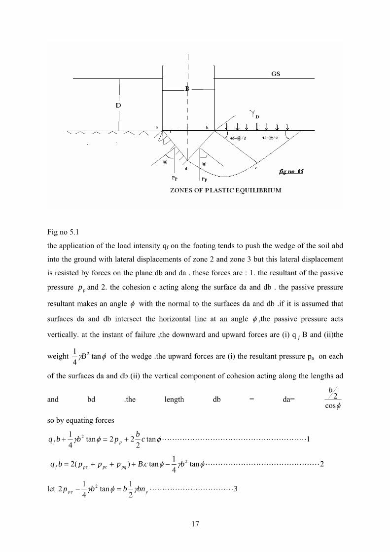
Fig no 5.1
the application of the load intensity qf on the footing tends to push the wedge of the soil abd
into the ground with lateral displacements of zone 2 and zone 3 but this lateral displacement
is resisted by forces on the plane db and da . these forces are : 1. the resultant of the passive
pressure and 2. the cohesion c acting along the surface da and db . the passive pressure
resultant makes an angle
pp
φ with the normal to the surfaces da and db .if it is assumed that
surfaces da and db intersect the horizontal line at an angle φ ,the passive pressure acts
vertically. at the instant of failure ,the downward and upward forces are (i) q B and (ii)the
weight
f
φγ tan41 2B of the wedge .the upward forces are (i) the resultant pressure pa on each
of the surfaces da and db (ii) the vertical component of cohesion acting along the lengths ad
and bd .the length db = da= φcos
2b
so by equating forces
1tan2
22tan41 2 LLLLLLLLLLLLLLLLLLLφφγ cbpbbq pf +=+
2tan41tan.)(2 2 LLLLLLLLLLLLLLLφγφγ bcBpppbq pqpcpf −+++=
let 321tan
412 2 LLLLLLLLLLLyp bnbbp γφγγ =−
17
4tan2 LLLLLLLLLLLLLLcpc bcnbcp =+ φ
2 5LLLLLLLLLLLLLLLLLqpq nbp σ=
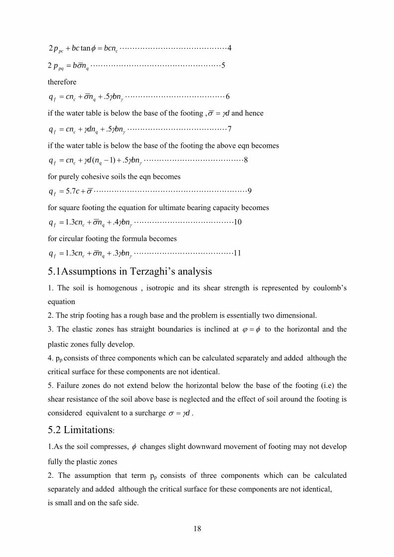
therefore
LLLLLLLLLLLLLγγσ bnncnq qcf 5.++= 6
if the water table is below the base of the footing , dγσ = and hence
75. LLLLLLLLLLLLLγγγ bndncnq qcf ++=
if the water table is below the base of the footing the above eqn becomes
85.)1( LLLLLLLLLLLLLγγγ bnndcnq qcf +−+=
for purely cohesive soils the eqn becomes
97.5 LLLLLLLLLLLLLLLLLLLLσ+= cq f
for square footing the equation for ultimate bearing capacity becomes
104.3.1 LLLLLLLLLLLLLγγσ bnncnq qcf ++=
for circular footing the formula becomes
113.3.1 LLLLLLLLLLLLLγγσ bnncnq qcf ++=
5.1Assumptions in Terzaghi’s analysis 1. The soil is homogenous , isotropic and its shear strength is represented by coulomb’s
equation
2. The strip footing has a rough base and the problem is essentially two dimensional.
3. The elastic zones has straight boundaries is inclined at φϕ = to the horizontal and the
plastic zones fully develop.
4. pp consists of three components which can be calculated separately and added although the
critical surface for these components are not identical.
5. Failure zones do not extend below the horizontal below the base of the footing (i.e) the
shear resistance of the soil above base is neglected and the effect of soil around the footing is
considered equivalent to a surcharge dγσ = .
5.2 Limitations:
1.As the soil compresses, φ changes slight downward movement of footing may not develop
fully the plastic zones
2. The assumption that term pp consists of three components which can be calculated
separately and added although the critical surface for these components are not identical,
is small and on the safe side.
18
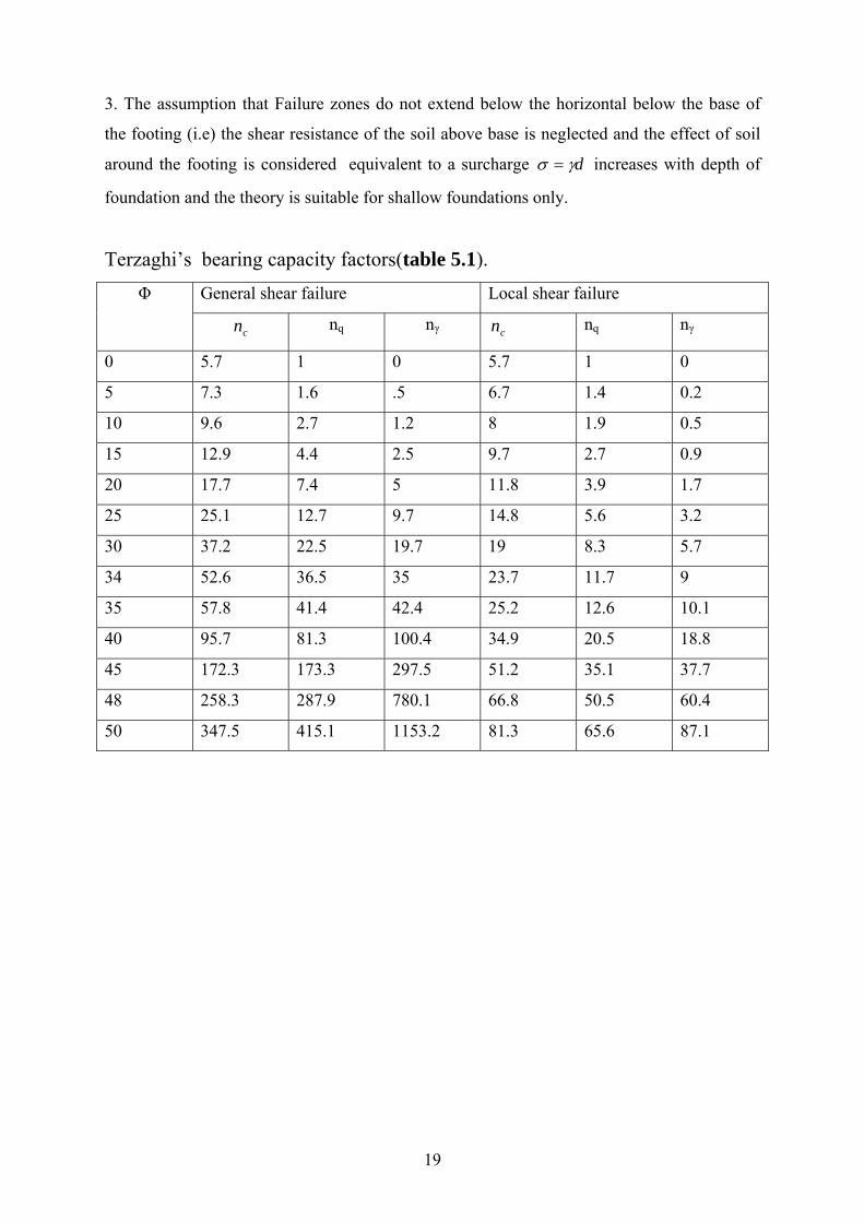
3. The assumption that Failure zones do not extend below the horizontal below the base of
the footing (i.e) the shear resistance of the soil above base is neglected and the effect of soil
around the footing is considered equivalent to a surcharge dγσ = increases with depth of
foundation and the theory is suitable for shallow foundations only.
Terzaghi’s bearing capacity factors(table 5.1). General shear failure Local shear failure Φ
cn nq nγ cn nq nγ
0 5.7 1 0 5.7 1 0
5 7.3 1.6 .5 6.7 1.4 0.2
10 9.6 2.7 1.2 8 1.9 0.5
15 12.9 4.4 2.5 9.7 2.7 0.9
20 17.7 7.4 5 11.8 3.9 1.7
25 25.1 12.7 9.7 14.8 5.6 3.2
30 37.2 22.5 19.7 19 8.3 5.7
34 52.6 36.5 35 23.7 11.7 9
35 57.8 41.4 42.4 25.2 12.6 10.1
40 95.7 81.3 100.4 34.9 20.5 18.8
45 172.3 173.3 297.5 51.2 35.1 37.7
48 258.3 287.9 780.1 66.8 50.5 60.4
50 347.5 415.1 1153.2 81.3 65.6 87.1
19
CHAPTER 6
MEYERHOF’S ANALYSIS
20

6. Meyerhof’s analysis: Meyerhof extended the analysis of plasic equilibrium of a surface footing to
shallow and deep foundations .the below figures show the failure mechanisms for shallow
and deep foundations. in this analysis abd is the elastic zone ,bde is the radial shear zone and
befg is the zone of mixed shear in which shear varies between radial and plane shear
depending upon the depth and roughness of the foundation. the plastic equilibrium in these
zones can be established frm the boundary conditions starting from the foundation shift.to
simplify this meyerhof established a factor β the angle to define the line bf,joining point b to f
where the assumed boundary failure slip intersects the soil surface .the resultant effect of
wedge of soil
bfg is represented by the normal and tangential stresses p0 and so on bf .the plane bf is termed
as equivalent free surface and p0 and so are termed as equivalent free surface stresses.the
angle β increases with depth and becomes 90 for deep foundations.
21

Fig no 6.2
meyerhof gave the following equations for ultimate bearing capacity,taking into account
shape, depth and inclination factors:
vertical load:
15. LLLLLLLLLLLLLLLLLLLLγγγγσ dsbndsndscnq qqqcccf ++=
for inclined load:
25. LLLLLLLLLLLLLLLLLLLLγγγγσ dsbndindicnq qqqcccf ++=
where
3)2
45(tan 2tan LLLLLLLLLLLLLLLLLLLLLφφπ += enq
4cot)1( LLLLLLLLLLLLLLLLLLLLLLLLLφ−= qc nn
5)4.1tan()1( LLLLLLLLLLLLLLLLLLLLLLLLφγ −= qnn
where
s = shape factors
d = depth factors
I = inclination factors
22
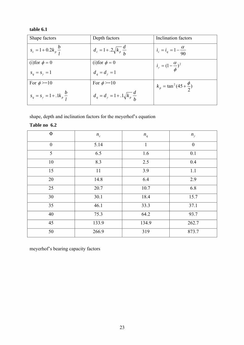
table 6.1
Shape factors Depth factors Inclination factors
lbks pc 2.01+=
bdkd pc 2.1+=
901 α−== qc ii
(i)for 0=φ
1== γssq
(i)for 0=φ
1== γddq
2)1(φα
γ −=i
For φ >=10
lbkss pq 1.1+== γ
For φ >=10
bdkdd pq 1.1+== γ
)2
45(tan 2 φ+=pk
shape, depth and inclination factors for the meyerhof’s equation
Table no 6.2
Φ cn qn γn
0 5.14 1 0
5 6.5 1.6 0.1
10 8.3 2.5 0.4
15 11 3.9 1.1
20 14.8 6.4 2.9
25 20.7 10.7 6.8
30 30.1 18.4 15.7
35 46.1 33.3 37.1
40 75.3 64.2 93.7
45 133.9 134.9 262.7
50 266.9 319 873.7
meyerhof’s bearing capacity factors
23

CHAPTER 7
COHESIVE SOILS
24
7 cohesive soils: Cohesive soil is one in which the major component of settlement is due to
consolidation, which is time dependant. All clays below the water table will undergo
consolidation under load irrespective of the actual facility for drainage or the number of
drainage faces ,the latter affecting only the time-rate of settlement and not the total settlement
due to consolidation .
Cohesionless soil: Sandy soils are considered to be cohesionless because their main source
of settlement is due to elastic deformation of the soil within the zone of influence under the
footing defined arbitrarily as the “bulb of pressure”. the sandy soil with which we conducted
our experiment was a cohesive soil.
25

CHAPTER 8
BEARING CAPACITY OF MODEL FOOTINGS ON
SAND
26
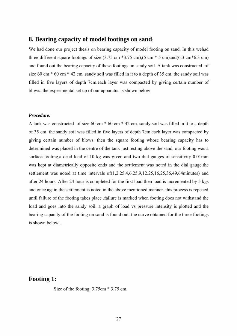
8. Bearing capacity of model footings on sand:
We had done our project thesis on bearing capacity of model footing on sand. In this wehad
three different square footings of size (3.75 cm *3.75 cm),(5 cm * 5 cm)and(6.3 cm*6.3 cm)
and found out the bearing capacity of these footings on sandy soil. A tank was constructed of
size 60 cm * 60 cm * 42 cm. sandy soil was filled in it to a depth of 35 cm. the sandy soil was
filled in five layers of depth 7cm.each layer was compacted by giving certain number of
blows. the experimental set up of our apparatus is shown below
Procedure:
A tank was constructed of size 60 cm * 60 cm * 42 cm. sandy soil was filled in it to a depth
of 35 cm. the sandy soil was filled in five layers of depth 7cm.each layer was compacted by
giving certain number of blows. then the square footing whose bearing capacity has to
determined was placed in the centre of the tank just resting above the sand. our footing was a
surface footing,a dead load of 10 kg was given and two dial gauges of sensitivity 0.01mm
was kept at diametrically opposite ends and the settlement was noted in the dial gauge.the
settlement was noted at time intervals of(1,2.25,4,6.25,9,12.25,16,25,36,49,64minutes) and
after 24 hours. After 24 hour is completed for the first load then load is incremented by 5 kgs
and once again the settlement is noted in the above mentioned manner. this process is repeaed
until failure of the footing takes place .failure is marked when footing does not withstand the
load and goes into the sandy soil. a graph of load vs pressure intensity is plotted and the
bearing capacity of the footing on sand is found out. the curve obtained for the three footings
is shown below .
Footing 1:
Size of the footing: 3.75cm * 3.75 cm.
27
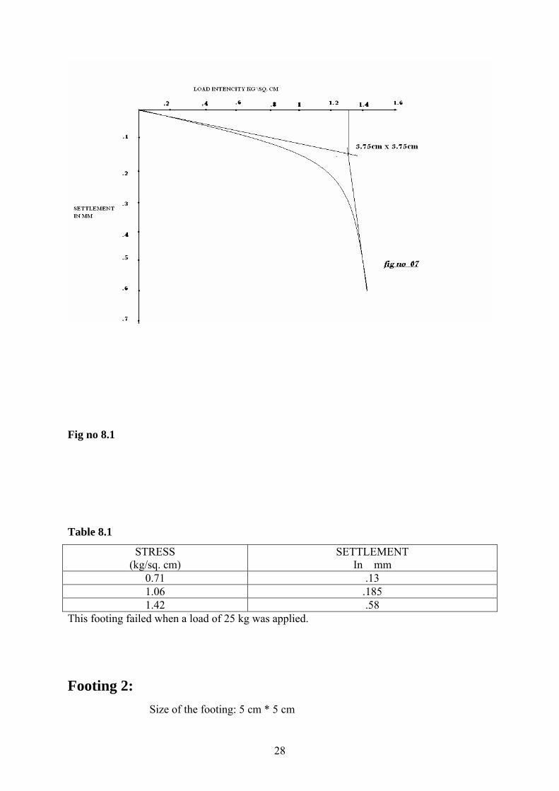
Fig no 8.1
Table 8.1
STRESS (kg/sq. cm)
SETTLEMENT In mm
0.71 .13 1.06 .185 1.42 .58
This footing failed when a load of 25 kg was applied.
Footing 2: Size of the footing: 5 cm * 5 cm
28
Fig no 8.2
Table 8.2
STRESS (kg/sq. cm)
SETTLEMENT In mm
0.4 .087 0.6 .12 0.8 .15 1 .18
1.2 .27 1.4 .62
This footing failed when a load of 40 kg was applied.
Footing 3: Size of the footing: 6.2 cm * 6.2 cm
29

Fig no 8.3
Table 8.3
STRESS (kg/sq. cm)
SETTLEMENT In mm
.26 .06
.39 .075
.52 .1
.65 .13
.78 .15
.91 .18 1.04 .19 1.17 .24 1.3 .36 1.43 .68
This footing failed when a load of 60 kg was applied.
30

CHAPTER 9
DIRECT SHEAR TEST
31
9. Direct shear test: To determine the bearing capacity of the square footing using terzaghi’s
equation Φ- angle of internal friction of sand is to be found out for determining the values of
required in the equation. for this reason direct shear test was performed on sanb. qnn ,γ
the shear strength of a soil is given by mohr-coulomb’s equation:
φσ tan+= cs
s = shear strength (kg\cm2)
σ = normal stress on failure plane(kg\cm2)
c= unit cohesion((kg\cm2)
Φ = angle of internal friction(degrees).
In a strength test of soil, there are two basic stages .first a normal load is applied to the
specimen and then failure is induced by appliying shear stress .If no water is allowed to
escape enter from or enter into specimen either during consolidation or during shearing then
it is called undrained test or unconsolidated undrained test (quick test).if specimen is allowed
to consolidate under normal load but no drainage of water is allowed during shear it is called
consolidated undrained test.if the specimen is consolidated under normal load and sheared
under fully drained conditions it is called consolidated drained 0r slow test.undrained tests
can be performed in a shear box only on highly impermeable clay.
Preparation of sample:
Since sand is a non-cohesive soil it is tamped in the shear box itself with the base plate and
grid plate or a porous stone as required in place at the bottom of the box.
Procedure:
1. The sandy soil is prepared as described above.the soil does not contain particles more than
4.75 mm size.
2.it is noted that the semations of both top and bottom grid plates are at right angles to the
direction of shear loading pad is placed on the top of the grid plate.
3. the box is transferred into the water jacket placed on the platform of apparatus provided
with adjustable loading frame.
4.the leverage ratio is determined and the desired normal load intensity at the range of 0.5 to
2 kg\cm2 is applied .the proving ring is adjusted so that it is attached spindle touches the
water jackets outer surface.
5.A dial gauge is attached to the fitting fixed to the vertical end plate.this gauge measures the
shear displacement.
6. Shear displacement at a rate of about 0.6mm\min is induced.
32
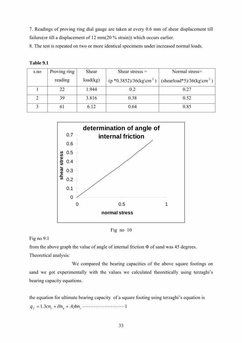
7. Readings of proving ring dial gauge are taken at every 0.6 mm of shear displacement till
failure(or till a displacement of 12 mm(20 % strain)) which occurs earlier.
8. The test is repeated on two or more identical specimens under increased normal loads.
Table 9.1
s.no Proving ring
reading
Shear
load(kg)
Shear stresss =
(p *0.3852)/36(kg\cm 2 )
Normal stress=
(shearload*5)/36(kg\cm )2
1 22 1.944 0.2 0.27
2 39 3.816 0.38 0.52
3 61 6.12 0.64 0.85
determination of angle of internal friction
0
0.1
0.2
0.3
0.4
0.5
0.6
0.7
0 0.5 1
normal stress
she
ar s
tress
Fig no 10
Fig no 9.1
from the above graph the value of angle of internal friction Φ of sand was 45 degrees.
Theoretical analysis:
We compared the bearing capacities of the above square footings on
sand we got experimentally with the values we calculated theoretically using terzaghi’s
bearing capacity equations.
the equation for ultimate bearing capacity of a square footing using terzaghi’s equation is
14.3.1 LLLLLLLLLγγσ bnncnq qcf ++=
33
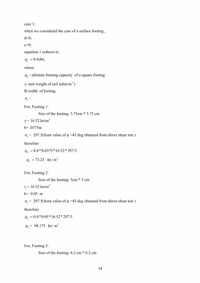
case 1:
when we considered the case of a surface footing ,
d=0;
c=0;
equation 1 reduces to
γγbnq f 4.0=
where
fq - ultimate bearing capacity of a square footing
γ- unit weight of soil in(kn\m 3 )
B-width of footing
γn -
For, Footing 1:
Size of the footing: 3.75cm * 3.75 cm
γ = 16.52 kn\m3
b= .0375m
γn = 297.5(from value of φ =45 deg obtained from direct shear test )
therefore
5.297*52.16*0375.0*4.0=fq
23.73=fq 2/ mkn
For, Footing 2:
Size of the footing: 5cm * 5 cm
γ = 16.52 kn\m3
b= 0.05 m
γn = 297.5(from value of φ =45 deg obtained from direct shear test )
therefore
5.297*52.16*05.0*4.0=fq
= 98.175 fq 2/ mkn
For, Footing 3:
Size of the footing: 6.2 cm * 6.2 cm
34

γ = 16.52 kn\m3
b= 0.062 m
γn = 297.5(from value of φ =45 deg obtained from direct shear test )
therefore: 5.297*52.16*062.0*4.0=fq
= 121.88 fq 2/ mkn
Table 9.2
From terzaghi’s equation the bearing capacity fot the above three square footings are:
Size of footing(cm 2 ) Ultimate bearing capacity( ) 2/ mkn
14.0625 73.123
25.00 98.175
38.44 121.88
case 2:
when the settlement of footing during failure is also taken into account:
terzaghi’s equation becomes
14. LLLLLLLLLγγσ bnnq qf +=
For, Footing 1:
Size of the footing: 3.75cm * 3.75 cm
γ = 16.52 kn\m3
b= .0375m
γn = 297.5(from value of φ =45 deg obtained from direct shear test )
qn = 173.3
d = 0.014 m
5.297*0375.0*52.16*4.03.173*014.0*52.16 +=fq
=fq 113.80 2/ mkn
For, Footing 2:
Size of the footing: 5 cm * 5 cm
γ = 16.52 kn\m3
b= .05m
35

γn = 297.5(from value of φ =45 deg obtained from direct shear test )
qn = 173.3
d = 0.023 m
5.297*5.0*52.16*4.03.173*023.0*52.16 +=fq
=fq 163.53 2/ mkn
For, Footing 3:
Size of the footing: 6.2 cm * 6.2 cm
γ = 16.52 kn\m3
b= .062m
γn = 297.5(from value of φ =45 deg obtained from direct shear test )
qn = 173.3
d = 0.037 m
5.297*062.0*52.16*4.03.173*037.0*52.16 +=fq
=fq 227.80 2/ mkn
Table 9.3
Ultimate Bearing capacity of footings from
graph (by model testing on footings)
Ultimate Bearing capacities by terzaghi’s
analysis Considering footings as surface
footings
126 2/ mkn
73.23 2/ mkn
129 2/ mkn
98.175 2/ mkn
135 2/ mkn
121.88 2/ mkn
36

.
Table 9.4
Ultimate Bearing capacity of footings from
graph (by model testing on footings)
Ultimate Bearing capacities by terzaghi’s
analysis Considering settlement of footing
during failure
126 2/ mkn
113.80 2/ mkn
129 2/ mkn 163.53 2/ mkn
135 2/ mkn
227.80 2/ mkn
37
CHAPTER 10
CONCLUSION
38
10.Conclusion:
Bearing capacity increases with the increase in size of model footing(square footing)on sand.
The value of ultimate bearing capacity obtained from performing load test on model footings
and that obtained from terzaghi’s analysis were found to vary slightly. the value obtained by
load test on footing was more than that obtained by terzaghi’s analysis. It is possible to
perform plate load test on model footings on a particular type of soil and these can be
incorporated to the field by considering suitable criterias and foundation for the particular
system can be laid.
11. References: 1. Punmia B.C. , soil mechanics and foundation ,laxmi publications, thirteenth edition.
2. Gopal ranjan, a text book on soil mechanics, tenth edition
3. Karl terzaghi., basics of soil mechanics and foundation engg
4. Braja m das , a text book on soil mechanics
5. http://www.wikipedia.com/
39