Embed Size (px)
Citation preview
BEARING CAPACITY OF CLAYS FOR
TOWER SILOS
INTRODUCTION
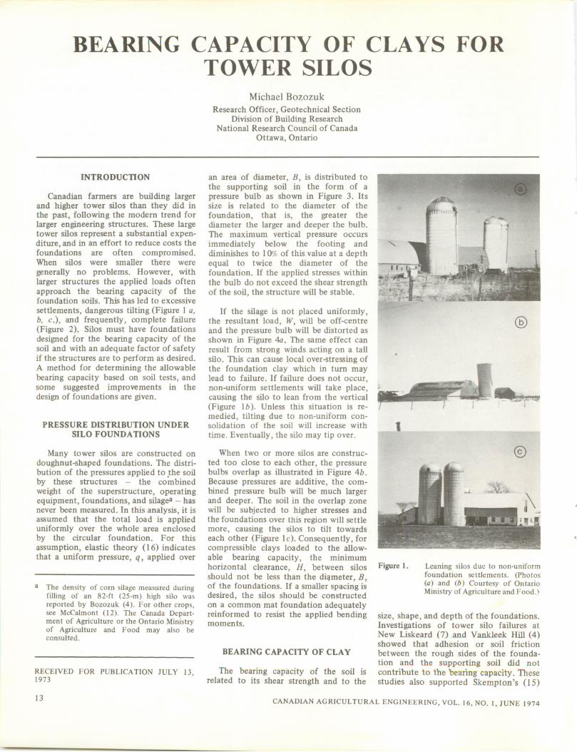
Canadian farmers are building largerand higher tower silos than they did inthe past, following the modern trend forlarger engineering structures. These largetower silos represent a substantial expenditure, and in an effort to reduce costs thefoundations are often compromised.When silos were smaller there were
generally no problems. However, withlarger structures the applied loads oftenapproach the bearing capacity of thefoundation soils. This has led to excessive
settlements, dangerous tilting (Figure 1 a,b, c), and frequently, complete failure(Figure 2). Silos must have foundationsdesigned for the bearing capacity of thesoil and with an adequate factor of safetyif the structures are to perform as desired.A method for determining the allowablebearing capacity based on soil tests, andsome suggested improvements in thedesign of foundations are given.
PRESSURE DISTRIBUTION UNDER
SILO FOUNDATIONS
Many tower silos are constructed ondoughnut-shaped foundations. The distribution of the pressures applied to the soilby these structures — the combinedweight of the superstructure, operatingequipment, foundations, and silage3 —hasnever been measured. In this analysis, it isassumed that the total load is applieduniformly over the whole area enclosedby the circular foundation. For thisassumption, elastic theory (16) indicatesthat a uniform pressure, q, applied over
a The density of corn silage measured duringfilling of an 82-ft (25-m) high silo wasreported by Bozozuk (4). For other crops,see McCalmont (12). The Canada Department of Agriculture or the Ontario Ministryof Agriculture and Food may also beconsulted.
RECEIVED FOR PUBLICATION JULY 13,1973
13
Michael Bozozuk
Research Officer, Geotechnical SectionDivision of Building Research
National Research Council of Canada
Ottawa, Ontario
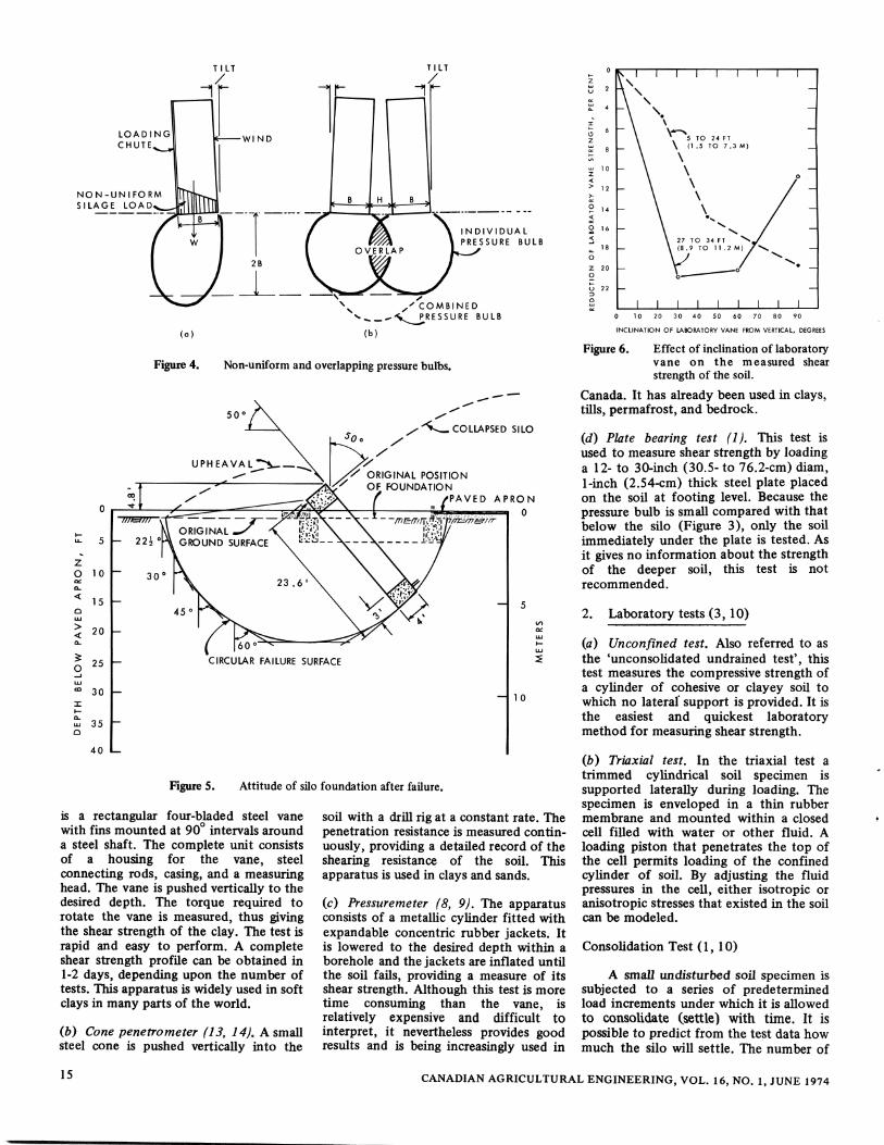
an area of diameter, B, is distributed tothe supporting soil in the form of apressure bulb as shown in Figure 3. Itssize is related to the diameter of the
foundation, that is, the greater thediameter the larger and deeper the bulb.The maximum vertical pressure occursimmediately below the footing anddiminishes to 10% of this value at a depthequal to twice the diameter of thefoundation. If the applied stresses withinthe bulb do not exceed the shear strengthof the soil, the structure will be stable.
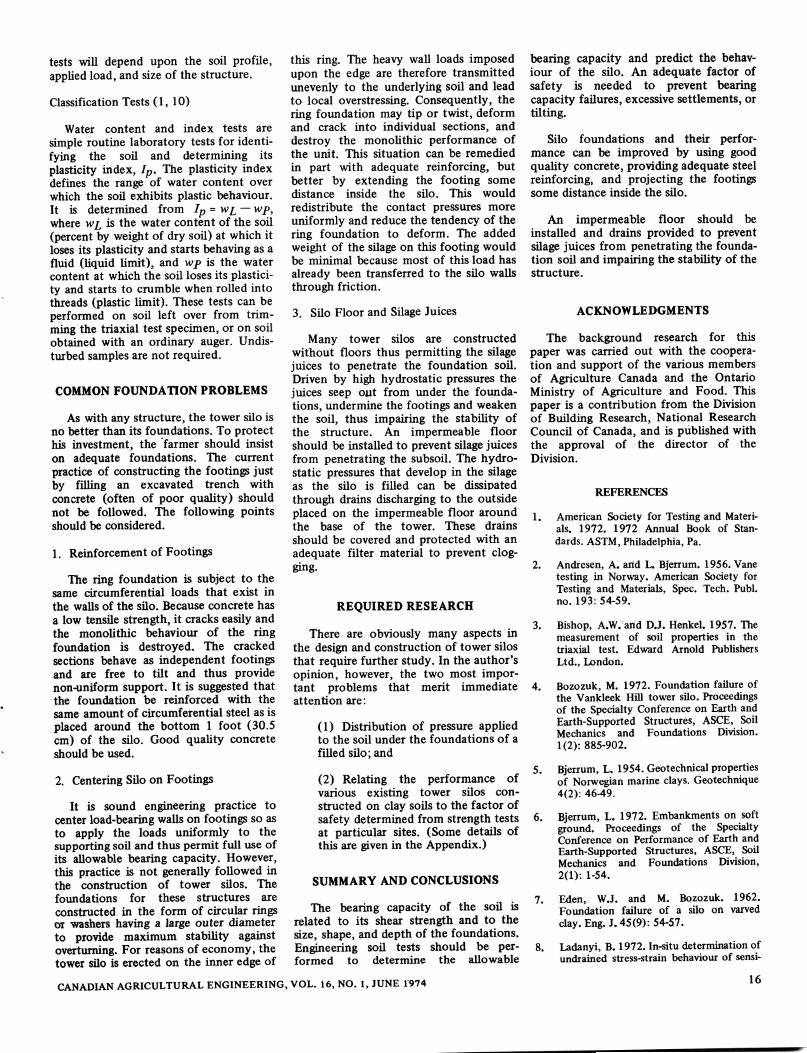
If the silage is not placed uniformly,the resultant load, W, will be off-centreand the pressure bulb will be distorted asshown in Figure 4a. The same effect canresult from strong winds acting on a tallsilo. This can cause local over-stressing ofthe foundation clay which in turn maylead to failure. If failure does not occur,non-uniform settlements will take place,causing the silo to lean from the vertical(Figure \b). Unless this situation is remedied, tilting due to non-uniform consolidation of the soil will increase with
time. Eventually, the silo may tip over.
When two or more silos are construc
ted too close to each other, the pressurebulbs overlap as illustrated in Figure 4b.Because pressures are additive, the combined pressure bulb will be much largerand deeper. The soil in the overlap zonewill be subjected to higher stresses andthe foundations over this region will settlemore, causing the silos to tilt towardseach other (Figure lc). Consequently, forcompressible clays loaded to the allowable bearing capacity, the minimumhorizontal clearance, H, between silosshould not be less than the diameter, B,of the foundations. If a smaller spacing isdesired, the silos should be constructedon a common mat foundation adequatelyreinformed to resist the applied bendingmoments.
BEARING CAPACITY OF CLAY
The bearing capacity of the soil isrelated to its shear strength and to the
©
Figure 1. Leaning silos due to non-uniformfoundation settlements. (Photos(a) and (fi) Courtesy of OntarioMinistry of Agriculture and Food.)
size, shape, and depth of the foundations.Investigations of tower silo failures atNew Liskeard (7) and Vankleek Hill (4)showed that adhesion or soil friction
between the rough sides of the foundation and the supporting soil did notcontribute to the bearing capacity. Thesestudies also supported Skempton's (15)
CANADIAN AGRICULTURAL ENGINEERING, VOL. 16, NO. 1, JUNE 1974
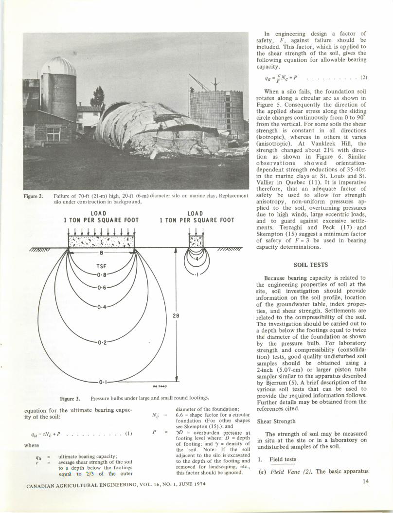
Figure 2. Failure of 70-ft (21-m) high, 20-ft (6-m) diameter silo on marine clay. Replacementsilo under construction in background.
/•VAVW
LOAD
1 TON PER SQUARE FOOTLOAD
1 TON PER SQUARE FOOT
Figure 3. Pressure bulbsunderlarge and small roundfootings.
equation for the ultimate bearing capacity of the soil:
qu =cNc + P
where
(1)
qu = ultimate bearingcapacity;c = average shear strength of the soil
to a depth below the footingsequal to 7)~!> oi the outer
diameter of the foundation;6.6 = shape factor for a circularfoundation (For other shapessee Skempton (15).); andyD = overburden pressure atfooting level where: D = depthof footing; and J = density ofthe soil. Note: If the soil
adjacent to the silo is excavatedto the depth of the footing andremoved for landscaping, etc.,this factor should be ignored.
CANADIAN AGRICULTURAL ENGINEERING, VOL. 16, NO. 1, JUNE 1974
In engineering design a factor ofsafety, F, against failure should beincluded. This factor, which is applied tothe shear strength of the soil, gives thefollowing equation for allowable bearingcapacity.
1a=§Nc+P (2)
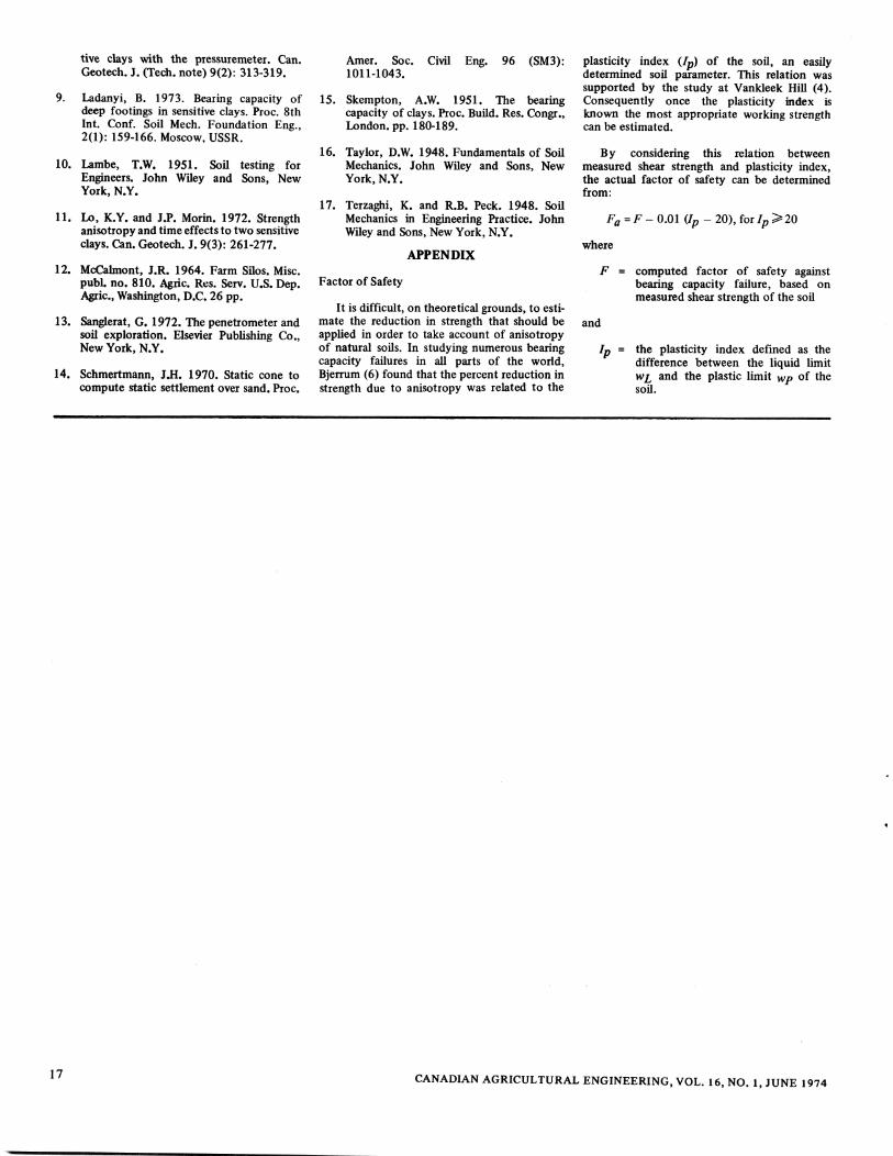
When a silo fails, the foundation soilrotates along a circular arc as shown inFigure 5. Consequently the direction ofthe applied shear stress along the slidingcircle changes continuously from 0 to 90from the vertical. For some soils the shear
strength is constant in all directions(isotropic), whereas in others it varies(anisotropic). At Vankleek Hill, thestrength changed about 21% with direction as shown in Figure 6. Similarobservations showed orientation-
dependent strength reductions of 35-40%in the marine clays at St. Louis and St.Vallier in Quebec (11). It is imperativetherefore, that an adequate factor ofsafety be used to allow for strengthanisotropy, non-uniform pressures applied to the soil, overturning pressuresdue to high winds, large eccentric loads,and to guard against excessive settlements. Terzaghi and Peck (17) andSkempton (15) suggest a minimum factorof safety of F = 3 be used in bearingcapacity determinations.
SOIL TESTS
Because bearing capacity is related tothe engineering properties of soil at thesite, soil investigation should provideinformation on the soil profile, locationof the groundwater table, index properties, and shear strength. Settlements arerelated to the compressibility of the soil.The investigation should be carried out toa depth below the footings equal to twicethe diameter of the foundation as shownby the pressure bulb. For laboratorystrength and compressibility (consolidation) tests, good quality undisturbed soilsamples should be obtained using a2-inch (5.07-cm) or larger piston tubesampler similar to the apparatus describedby Bjerrum (5). A brief description of thevarious soil tests that can be used toprovide the required information follows.Further details may be obtained from thereferences cited.
Shear Strength
The strength of soil may be measuredin situ at the site or in a laboratory onundisturbed samples of the soil.
1. Field tests
(a) Field Vane (2). The basic apparatus
14
NON-UNIFORM
SILAGE LOAD
NDIVIDUAL
ESSURE BULB
' COMBINED
PRESSURE BULB
Non-uniform and overlapping pressure bulbs.
COLLAPSED SILO
jy ORIGINAL POSITION' OF FOUNDATION
PAVED APRON
0
Figure 5. Attitude of silo foundation after failure.
is a rectangular four-bladed steel vanewith fins mounted at 90° intervals arounda steel shaft. The complete unit consistsof a housing for the vane, steelconnecting rods, casing, and a measuringhead. The vane is pushed vertically to thedesired depth. The torque required torotate the vane is measured, thus givingthe shear strength of the clay. The test israpid and easy to perform. A completeshear strength profile can be obtained in1-2 days, depending upon the number oftests. This apparatus is widely used in softclays in many parts of the world.
(b) Cone penetrometer (13, 14). A smallsteel cone is pushed vertically into the
soil with a drill rig at a constant rate. Thepenetration resistance is measured continuously, providing a detailed record of theshearing resistance of the soil. Thisapparatus is used in clays and sands.
(c) Pressuremeter (8, 9). The apparatusconsists of a metallic cylinder fitted withexpandable concentric rubber jackets. Itis lowered to the desired depth within aborehole and the jackets are inflated untilthe soil fails, providing a measure of itsshear strength. Although this test is moretime consuming than the vane, isrelatively expensive and difficult tointerpret, it nevertheless provides goodresults and is being increasingly used in
I I I I 1 i i
0 10 20 30 40 50 60 70 80 90
INCLINATION OF LABORATORY VANE FROM VERTICAL, DEGREES
Figure 6. Effect of inclination of laboratoryvane on the measured shear
strength of the soil.
Canada. It has already been used in clays,tills, permafrost, and bedrock.
(d) Plate bearing test (1). This test isused to measure shear strength by loadinga 12- to 30-inch (30.5- to 76.2-cm) diam,1-inch (2.54-cm) thick steel plate placedon the soil at footing level. Because thepressure bulb is small compared with thatbelow the silo (Figure 3), only the soilimmediately under the plate is tested. Asit gives no information about the strengthof the deeper soil, this test is notrecommended.
2. Laboratory tests (3, 10)
(a) Unconfined test. Also referred to asthe 'unconsolidated undrained test', thistest measures the compressive strength ofa cylinder of cohesive or clayey soil towhich no lateral' support is provided. It isthe easiest and quickest laboratorymethod for measuring shear strength.
(b) Triaxial test. In the triaxial test atrimmed cylindrical soil specimen issupported laterally during loading. Thespecimen is enveloped in a thin rubbermembrane and mounted within a closedcell filled with water or other fluid. Aloading piston that penetrates the top ofthe cell permits loading of the confinedcylinder of soil. By adjusting the fluidpressures in the cell, either isotropic oranisotropic stresses that existed in the soilcan be modeled.
Consolidation Test (1,10)
A small undisturbed soil specimen issubjected to a series of predeterminedload increments under which it is allowed
to consolidate (settle) with time. It ispossible to predict from the test data howmuch the silo will settle. The number of
15 CANADIAN AGRICULTURAL ENGINEERING, VOL. 16, NO. 1, JUNE 1974
tests will depend upon the soil profile,applied load, and size of the structure.
Classification Tests (1,10)
Water content and index tests aresimple routine laboratory tests for identifying the soil and determining itsplasticity index, Ip. The plasticity indexdefines the range of water content overwhich the soil exhibits plastic behaviour.It is determined from Ip = wi~ wp,where wi is the water content of the soil(percent by weight of dry soil) at which itloses its plasticity and starts behaving as afluid (liquid limit), and wp is the watercontent at which the soil loses its plasticity and starts to crumble when rolled intothreads (plastic limit). These tests can beperformed on soil left over from trimming the triaxial test specimen, or on soilobtained with an ordinary auger. Undisturbed samples are not required.
COMMON FOUNDATION PROBLEMS
As with any structure, the tower silo isno better than its foundations. To protecthis investment, the farmer should insiston adequate foundations. The currentpractice of constructing the footings justby filling an excavated trench withconcrete (often of poor quality) shouldnot be followed. The following pointsshould be considered.
1. Reinforcement of Footings
The ring foundation is subject to thesame circumferential loads that exist inthe walls of the silo. Because concrete hasa low tensile strength, it cracks easily andthe monolithic behaviour of the ringfoundation is destroyed. The crackedsections behave as independent footingsand are free to tilt and thus providenon-uniform support. It is suggested thatthe foundation be reinforced with thesame amount of circumferential steel as isplaced around the bottom 1 foot (30.5cm) of the silo. Good quality concreteshould be used.
2. Centering Silo on Footings
It is sound engineering practice tocenter load-bearing walls on footings so asto apply the loads uniformly to thesupporting soil and thus permit full use ofits allowable bearing capacity. However,this practice is not generally followed inthe construction of tower silos. Thefoundations for these structures areconstructed in the form of circular ringsor washers having a large outer diameterto provide maximum stability againstoverturning. For reasons of economy, thetower silo is erected on the inner edge of
this ring. The heavy wall loads imposedupon the edge are therefore transmittedunevenly to the underlying soil and leadto local overstressing. Consequently, thering foundation may tip or twist, deformand crack into individual sections, anddestroy the monolithic performance ofthe unit. This situation can be remediedin part with adequate reinforcing, butbetter by extending the footing somedistance inside the silo. This wouldredistribute the contact pressures moreuniformly and reduce the tendency of thering foundation to deform. The addedweight of the silage on this footing wouldbe minimal because most of this load hasalready been transferred to the silo wallsthrough friction.
3. Silo Floor and Silage Juices
Many tower silos are constructedwithout floors thus permitting the silagejuices to penetrate the foundation soil.Driven by high hydrostatic pressures thejuices seep out from under the foundations, undermine the footings and weakenthe soil, thus impairing the stability ofthe structure. An impermeable floorshould be installed to prevent silage juicesfrom penetrating the subsoil. The hydrostatic pressures that develop in the silageas the silo is filled can be dissipatedthrough drains discharging to the outsideplaced on the impermeable floor aroundthe base of the tower. These drainsshould be covered and protected with anadequate filter material to prevent clogging.
bearing capacity and predict the behaviour of the silo. An adequate factor ofsafety is needed to prevent bearingcapacity failures, excessive settlements, ortilting.
Silo foundations and their performance can be improved by using goodquality concrete, providing adequate steelreinforcing, and projecting the footingssome distance inside the silo.
An impermeable floor should beinstalled and drains provided to preventsilage juices from penetrating the foundation soil and impairing the stability of thestructure.
REQUIRED RESEARCH
There are obviously many aspects inthe design and construction of tower silosthat require further study. In the author'sopinion, however, the two most important problems that merit immediateattention are:
(1) Distribution of pressure appliedto the soil under the foundations of afilled silo; and
(2) Relating the performance ofvarious existing tower silos constructed on clay soils to the factor ofsafety determined from strength testsat particular sites. (Some details ofthis are given in the Appendix.)
SUMMARY AND CONCLUSIONS
The bearing capacity of the soil isrelated to its shear strength and to thesize, shape, and depth of the foundations.Engineering soil tests should be performed to determine the allowable
ACKNOWLEDGMENTS
The background research for thispaper was carried out with the cooperation and support of the various membersof Agriculture Canada and the OntarioMinistry of Agriculture and Food. Thispaper is a contribution from the Divisionof Building Research, National ResearchCouncil of Canada, and is published withthe approval of the director of theDivision.
REFERENCES
1. American Society for Testing and Materials. 1972. 1972 Annual Book of Stan
dards. ASTM, Philadelphia, Pa.
2. Andresen, A. arid L. Bjerrum. 1956. Vanetesting in Norway. American Society forTesting and Materials, Spec. Tech. Publ.no. 193: 54-59.
3. Bishop, A.W. arid DJ. Henkel. 1957. Themeasurement of soil properties in thetriaxial test. Edward Arnold Publishers
Ltd., London.
4. Bozozuk, M. 1972. Foundation failure ofthe Vankleek Hill tower silo. Proceedingsof the Specialty Conference on Earth andEarth-Supported Structures, ASCE, SoilMechanics and Foundations Division.1(2): 885-902.
5. Bjerrum, L. 1954.Geotechnical propertiesof Norwegian marine clays. Geotechnique4(2): 46-49.
6. Bjerrum, L. 1972. Embankments on softground. Proceedings of the SpecialtyConference on Performance of Earth andEarth-Supported Structures, ASCE, SoilMechanics and Foundations Division,2(1): 1-54.
7. Eden, W.J. and M. Bozozuk. 1962.Foundation failure of a silo on varvedclay. Eng. J. 45(9): 54-57.
8. Ladanyi, B. 1972. In-situ determination ofundrained stress-strain behaviour of sensi-
CANADIAN AGRICULTURAL ENGINEERING, VOL. 16, NO. 1, JUNE 1974 16
tive clays with the pressuremeter. Can.Geotech. J. (Tech. note) 9(2): 313-319.
9. Ladanyi, B. 1973. Bearing capacity ofdeep footings in sensitive clays. Proc. 8thInt. Conf. Soil Mech. Foundation Eng.,2(1): 159-166. Moscow, USSR.
10. Lambe, T.W. 1951. Soil testing forEngineers. John Wiley and Sons, NewYork, N.Y.
11. Lo, K.Y. and J.P. Morin. 1972. Strengthanisotropy and time effects to two sensitiveclays. Can. Geotech. J. 9(3): 261-277.
12. McCalmont, J.R. 1964. Farm Silos. Misc.pubL no. 810. Agric. Res. Serv. U.S. Dep.Agric, Washington, D.C. 26 pp.
13. Sanglerat, G. 1972. The penetrometer andsoil exploration. Elsevier Publishing Co.,New York, N.Y.
14. Schmertmann, J.H. 1970. Static cone tocompute static settlement over sand. Proc.
17
Amer. Soc. Civil Eng. 96 (SM3):1011-1043.
15. Skempton, A.W. 1951. The bearingcapacity of clays. Proc. Build. Res. Congr.,London, pp. 180-189.
16. Taylor, D.W. 1948. Fundamentals of SoilMechanics. John Wiley and Sons, NewYork, N.Y.
17. Terzaghi, K. and R.B. Peck. 1948. SoilMechanics in Engineering Practice. JohnWiley and Sons, New York, N.Y.
APPENDIX
Factor of Safety
It is difficult, on theoretical grounds, to estimate the reduction in strength that should beapplied in order to take account of anisotropyof natural soils. In studying numerous bearingcapacity failures in all parts of the world,Bjerrum (6) found that the percent reduction instrength due to anisotropy was related to the
plasticity index (Ip) of the soil, an easilydetermined soil parameter. This relation wassupported by the study at Vankleek Hill (4).Consequently once the plasticity index isknown the most appropriate working strengthcan be estimated.
By considering this relation betweenmeasured shear strength and plasticity index,the actual factor of safety can be determinedfrom:
Fa=F- 0.01 (Ip - 20), for Ip >20
where
F =
and
computed factor of safety againstbearing capacity failure, based onmeasured shear strength of the soil
Ip = the plasticity index defined as thedifference between the liquid limitwi and the plastic limit Wp of thesoil.
CANADIAN AGRICULTURAL ENGINEERING, VOL. 16, NO. 1, JUNE 1974