Embed Size (px)
Citation preview

Limit StateS DeSign
beamS, CoLumnS & HeaDerS
ICBO ES ER-5598 n HUD MR 1310 DSA PA-123 n LAC RR25448 n CCMC 13006-R
2
WOOD—THE MIRACLE MATERIAL
Wood is the right choice for a host of construction applications. It is the earth’s natural, energy efficient and renewable building material.
EngInEERED WOOD IS A BETTER USE Of WOOD
The miracle in today’s wood products is that they make more efficient use of the wood fiber resource to make stronger plywood, oriented strand board, I-joists, glued laminated timbers and laminated veneer lumber. That’s good for the environment, and good for designers seeking strong, efficient and striking building design.
A fEW fACTS ABOUT WOOD
We’re growing more wood every day. Forests fully cover one-third of the United States’ and one-half of Canada’s land mass. American landowners plant more than two billion trees every year.
In addition, millions of trees seed naturally. The forest products industry, which comprises about 15 percent of forestland ownership, is responsible for 41 percent of replanted forest acreage. That works out to more than one billion trees a year, or about three million trees planted every day. This high rate of replanting accounts for the fact that each year, 27 percent more timber is grown than
is harvested. Canada’s replanting record shows a fourfold increase in the number of trees planted between 1975 and 1990.
Life Cycle Assessment shows wood is the greenest building product. A 2004 CORRIM study gave scientific validation to the strength of wood as a green building product. In examining building products’ life cycles—from extraction of the raw material to demolition of the building at the end of its long lifespan—CORRIM found that wood was better for the environment than steel or concrete in terms of embodied energy, global warming potential, air emissions, water emissions, and solid waste production. For the complete details of the report, visit www.CORRIM.org.
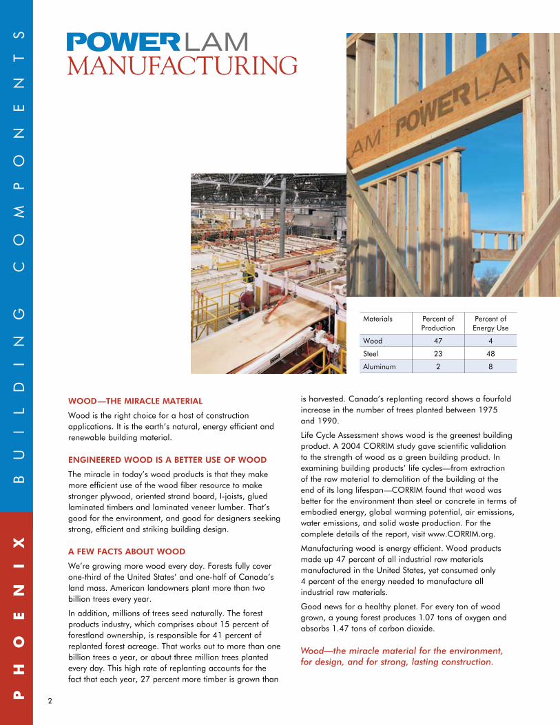
Manufacturing wood is energy efficient. Wood products made up 47 percent of all industrial raw materials manufactured in the United States, yet consumed only 4 percent of the energy needed to manufacture all industrial raw materials.
Good news for a healthy planet. For every ton of wood grown, a young forest produces 1.07 tons of oxygen and absorbs 1.47 tons of carbon dioxide.
Wood—the miracle material for the environment, for design, and for strong, lasting construction.
Materials Percent of Production
Percent of Energy Use
Wood 47 4
Steel 23 48
Aluminum 2 8
Ph
oe
ni
x
B
UI
Ld
In
G
CO
MP
On
En
TS
manufaCturing
3
HanDLing & inStaLLation• POWERLAMshouldbestoredlyingflatandprotected
from the weather.
• Keepthematerialabovegroundtominimizetheabsorption of ground moisture and allow circulation of air.
• POWERLAMisforuseincovered,dryconditionsonly.Protect from the weather on the job site both before and after installation.
• Exceptforcuttingtolength,POWERLAMshallnotbecut,drilled or notched. Heel cuts may be possible. Contact your Phoenix Building Components representative.
•DonotinstallanydamagedLVL.
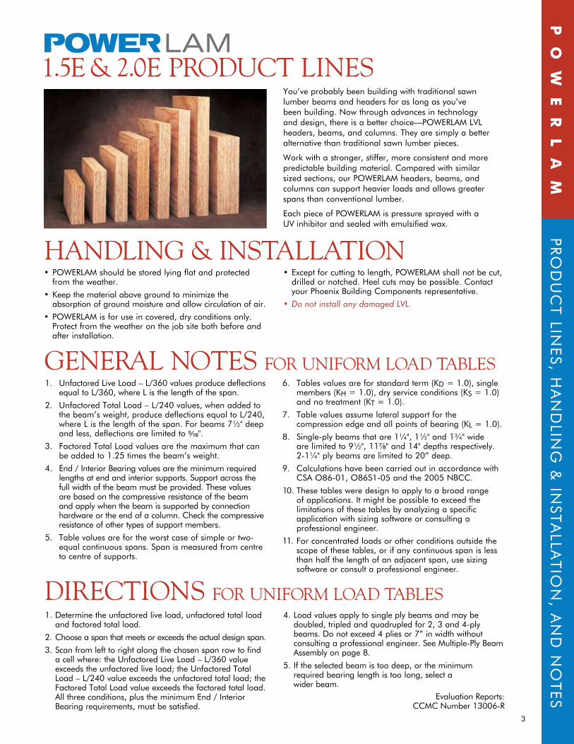
You’ve probably been building with traditional sawn lumber beams and headers for as long as you’ve been building. now through advances in technology and design, there is a better choice—POWERLAM LVL headers, beams, and columns. They are simply a better alternative than traditional sawn lumber pieces.
Work with a stronger, stiffer, more consistent and more predictable building material. Compared with similar sizedsections,ourPOWERLAMheaders,beams,andcolumns can support heavier loads and allows greater spans than conventional lumber.
Each piece of POWERLAM is pressure sprayed with a UV inhibitor and sealed with emulsified wax.
Po
We
RL
AM
PRO
dU
CT LIn
ES, H
An
dLIn
G &
InSTA
LLATIO
n, A
nd
nO
TES
1.5e & 2.0e ProDuCt LineS
1. Unfactored Live Load – L/360 values produce deflections equal to L/360, where L is the length of the span.
2. Unfactored Total Load – L/240 values, when added to the beam’s weight, produce deflections equal to L/240, where L is the length of the span. For beams 7½" deep and less, deflections are limited to B\zn".
3. Factored Total Load values are the maximum that can be added to 1.25 times the beam’s weight.
4. End / Interior Bearing values are the minimum required lengths at end and interior supports. Support across the full width of the beam must be provided. These values are based on the compressive resistance of the beam and apply when the beam is supported by connection hardware or the end of a column. Check the compressive resistance of other types of support members.
5. Table values are for the worst case of simple or two-equal continuous spans. Span is measured from centre to centre of supports.
6. Tablesvaluesareforstandardterm(Kd = 1.0), single members(KH=1.0),dryserviceconditions(KS = 1.0) andnotreatment(KT = 1.0).
7. Table values assume lateral support for the compressionedgeandallpointsofbearing(KL = 1.0).
8. Single-ply beams that are 1¼", 1½" and 1¾" wide are limited to 9½", 11M\," and 14" depths respectively. 2-1¼" ply beams are limited to 20” deep.
9. Calculations have been carried out in accordance with CSA O86-01, O86S1-05 and the 2005 nBCC.
10. These tables were design to apply to a broad range of applications. It might be possible to exceed the limitationsofthesetablesbyanalyzingaspecificapplicationwithsizingsoftwareorconsultingaprofessional engineer.
11. For concentrated loads or other conditions outside the scope of these tables, or if any continuous span is less thanhalfthelengthofanadjacentspan,usesizingsoftware or consult a professional engineer.
1. determine the unfactored live load, unfactored total load and factored total load.
2. Choose a span that meets or exceeds the actual design span.
3. Scan from left to right along the chosen span row to find a cell where: the Unfactored Live Load – L/360 value exceeds the unfactored live load; the Unfactored Total Load – L/240 value exceeds the unfactored total load; the Factored Total Load value exceeds the factored total load. All three conditions, plus the minimum End / Interior Bearing requirements, must be satisfied.
4. Load values apply to single ply beams and may be doubled, tripled and quadrupled for 2, 3 and 4-ply beams. do not exceed 4 plies or 7” in width without consulting a professional engineer. See Multiple-Ply Beam Assembly on page 8.
5. If the selected beam is too deep, or the minimum required bearing length is too long, select a wider beam.
Evaluation Reports: CCMC number 13006-R
generaL noteS for uniform LoaD tabLeS
DireCtionS for uniform LoaD tabLeS
4Po
We
RL
AM
1.
5e
F
AC
TO
RE
d
RE
SI
ST
An
CE
For additional grades and sizes, please contact your Phoenix Building Components representative.
1.5e PoWeRLAM AvAiLAbLe SizeS
11⁄2” 1.5E PoWeRLAM 5Z\x” 7Z\v” 9Z\x” 11M\,” 14” 16”
13⁄4” 1.5E PoWeRLAM 5Z\x” 7Z\v” 9Z\x” 11M\,” 14” 16”
31⁄2” 1.5E PoWeRLAM5Z\x” 7Z\v” 9Z\x” 11M\,” 14” 16”
1.5e faCtoreD reSiStanCe1½” x 1.5E POWERLAMBeam depth 5Z\x” 7Z\v” 9Z\v” 9Z\x” 11Z\v” 11M\,” 14” 16” 18” 18C\v” 20” 22” 23M\,”Factored Moment Resistance [ft-lbs](2) 2757 4532 7027 7373 9995 11017 14817 18842 23292 25068 28156 33426 38728
Factored Shear Resistance [lbs](3) 2104 2773 3538 3634 4303 4542 5355 6120 6885 7172 7650 8415 9132
EI [x 106 lbs-in2](4) 31 71 148 161 267 314 515 768 1094 1236 1500 1997 2552Weight [plf] 2.1 2.8 3.6 3.7 4.4 4.6 5.5 6.2 7.0 7.3 7.8 8.6 9.3
1¾” x 1.5E POWERLAMBeam depth 5Z\x” 7Z\v” 9Z\v” 9Z\x” 11Z\v” 11M\,” 14” 16” 18” 18C\v” 20” 22” 23M\,”Factored Moment Resistance [ft-lbs](2) 3216 5288 8198 8601 11661 12853 17286 21983 27174 29246 32849 38997 45182
Factored Shear Resistance [lbs](3) 2454 3235 4128 4239 5020 5299 6248 7140 8033 8367 8925 9818 10654
EI [x 106 lbs-in2](4) 36 83 173 188 311 366 600 896 1276 1442 1750 2329 2977Weight [plf] 2.5 3.3 4.2 4.3 5.1 5.4 6.4 7.3 8.2 8.5 9.1 10.0 10.9
3½” x 1.5E POWERLAMBeam depth 5Z\x” 7Z\v” 9Z\v” 9Z\x” 11Z\v” 11M\,” 14” 16” 18” 18C\v” 20” 22” 23M\,”Factored Moment Resistance [ft-lbs](2) 6432 10576 16397 17203 23322 25706 34572 43966 54349 58493 65698 77994 90364
Factored Shear Resistance [lbs](3) 4909 6471 8256 8479 10041 10598 12495 14280 16065 16734 17850 19635 21308
EI [x 106 lbs-in2](4) 73 167 346 375 623 733 1201 1792 2552 2884 3500 4659 5954Weight [plf] 5.0 6.6 8.4 8.6 10.2 10.8 12.7 14.5 16.4 17.0 18.2 20.0 21.7
1. Calculations have been carried out in accordance with CSA O86-01 and O86S1-052. �ϕ=0.9;standardterm,Kd=1.0;singlemember,KH=1.0;dryserviceconditions,KSb=1.0;notreatment,KT=1.0;KZb = (12/d)1/5; lateral support at points of bearing and the
compressionedge,KL = 1.03. ϕ=0.9;standardterm,Kd=1.0;dryserviceconditions,KSv=1.0;notreatment,KT=1.0;KZv = 1.04.Dryserviceconditions,KSE=1.0;notreatment,KTE = 1.0
PRoduct identificAtionAPA EWS
0.0E-0000FCCMC 13006-R
PACIFIC WOOdTECH 1047
MM/dd/YY
SPecific GRAvity And equivALent SPecieS foR fASteneR deSiGn
nail or Bolt face(1) Edge(2)
nail—Withdrawal 0.50, d. Fir - Larch 0.47, W. Hemlocknail—Lateral 0.50, d. Fir - Larch 0.50, d. Fir - LarchBolt—Lateral 0.50, d. Fir - Larch 0.50, d. Fir - Larch
1. Face: Member faces showing the face of one veneer, typically the wide faces of the member
2. Edge: Member faces showing the narrow edge of all veneers, typically the narrow faces of the member.
fASteneR SPAcinG—edGe
POWERLAM Dimensions fastener Minimum Spacing
Minimum ¾ inches thick and 3½ inches deep
2½” common wire nail 3”3” common wire nail 4”
3¼” common wire nail 4”3½” common wire nail not Permitted
14 Gage Staple 4”
Minimum 1¼ inches thick and 3½ inches deep
3” common wire nail 4”3¼” common wire nail 4”3½” common wire nail 6”(1)
14 Gage Staple 4”
1. May be 4” when nailing through bottom wall plate and sheathing (maximum 1C\,” penetration)
POWERLAM components shall be designed in accordance with CSA O86-01, EngineeredDesigninWood
1.5E PoWeRLAM Specified Strength and Stiffness(1)
Modulus of Elasticity E (edge) = 1,500,000 psi (flat) = 1,500,000 psi
Flexural Stress Fb (edge) = 4,158 psi(2)
(flat) = 4,158 psi(3)
HorizontalShearFv (edge) = 425 psi Fv (flat) = 255 psi
Compression Perpendicular to Grain Fcp (edge) = 1,365 psi (flat) = 819 psi
Tension Parallel to Grain Ft = 2,360 psi(4)
Compression Parallel to Grain Fc = 3,112 psi
1. Calculations have been carried out in accordance with CSA O86-01 and O86S1-052. MultiplybyKZb = (12/d)1/5, where d = depth of member [in].
KZb = 1.47 for d < 3.5 inches3. MultiplybyKZb = (1.75/d)1/5, where d = depth of member [in].
KZb = 1.00 for d < 1.75 inches4. MultiplybyKZt = (20/L)1/10, where L = length of member [ft].
KZt = 1.17 for L < 4 feet
5
For additional grades and sizes, please contact your Phoenix Building Components representative.
2.0e faCtoreD reSiStanCe1½” x 2.0E POWERLAMBeam depth 5Z\x” 7Z\v” 9Z\v” 9Z\x” 11Z\v” 11M\,” 14” 16” 18” 18C\v” 20” 22” 23M\,”Factored Moment Resistance [ft-lbs](2) 3798 6245 9682 10158 13772 15179 20415 25962 32093 34540 38795 46055 53360
Factored Shear Resistance [lbs](3) 2624 3458 4412 4532 5366 5664 6678 7632 8586 8944 9540 10494 11388
EI [x 106 lbs-in2](4) 42 95 198 214 356 419 686 1024 1458 1648 2000 2662 3402Weight [plf] 2.1 2.8 3.6 3.7 4.4 4.6 5.5 6.2 7.0 7.3 7.8 8.6 9.3
1¾” x 2.0E POWERLAMBeam depth 5Z\x” 7Z\v” 9Z\v” 9Z\x” 11Z\v” 11M\,” 14” 16” 18” 18C\v” 20” 22” 23M\,”Factored Moment Resistance [ft-lbs](2) 4431 7286 11296 11851 16067 17709 23817 30289 37442 40296 45260 53731 62253
Factored Shear Resistance [lbs](3) 3061 4035 5148 5287 6261 6608 7791 8904 10017 10434 11130 12243 13286
EI [x 106 lbs-in2](4) 49 111 231 250 415 488 800 1195 1701 1923 2333 3106 3969Weight [plf] 2.5 3.3 4.2 4.3 5.1 5.4 6.4 7.3 8.2 8.5 9.1 10.0 10.9
3½” x 2.0E POWERLAMBeam depth 5Z\x” 7Z\v” 9Z\v” 9Z\x” 11Z\v” 11M\,” 14” 16” 18” 18C\v” 20” 22” 23M\,”Factored Moment Resistance [ft-lbs](2) 8862 14571 22592 23703 32134 35419 47635 60577 74883 80593 90521 107462 124506
Factored Shear Resistance [lbs](3) 6122 8069 10295 10574 12521 13217 15582 17808 20034 20869 22260 24486 26573
EI [x 106 lbs-in2](4) 97 222 462 500 831 977 1601 2389 3402 3845 4667 6211 7939Weight [plf] 5.0 6.6 8.4 8.6 10.2 10.8 12.7 14.5 16.4 17.0 18.2 20.0 21.7
1. Calculations have been carried out in accordance with CSA O86-01 and O86S1-052. ϕ=0.9;standardterm,Kd=1.0;singlemember,KH=1.0;dryserviceconditions,KSb=1.0;notreatment,KT=1.0;KZb = (12/d)1/5; lateral support at points of bearing and the
compressionedge,KL = 1.03. ϕ=0.9;standardterm,Kd=1.0;dryserviceconditions,KSv=1.0;notreatment,KT=1.0;KZv = 1.04.Dryserviceconditions,KSE=1.0;notreatment,KTE = 1.0
PRoduct identificAtion APA EWS
0.0E-0000FCCMC 13006-R
PACIFIC WOOdTECH 1047
MM/dd/YY
SPecific GRAvity And equivALent SPecieS foR fASteneR deSiGn
nail or Bolt face(1) Edge(2)
nail—Withdrawal 0.50, d. Fir - Larch 0.47, W. Hemlocknail—Lateral 0.50, d. Fir - Larch 0.50, d. Fir - LarchBolt—Lateral 0.50, d. Fir - Larch 0.50, d. Fir - Larch
1. Face: Member faces showing the face of one veneer, typically the wide faces of the member
2. Edge: Member faces showing the narrow edge of all veneers, typically the narrow faces of the member
fASteneR SPAcinG—edGe
POWERLAM Dimensions fastener Minimum Spacing
Minimum ¾ inches thick and 3½ inches deep
2½” common wire nail 3”3” common wire nail 4”
3¼” common wire nail 4”3½” common wire nail not Permitted
14 Gage Staple 4”
Minimum 1¼ inches thick and 3½ inches deep
3” common wire nail 4”3¼” common wire nail 4”3½” common wire nail 6”(1)
14 Gage Staple 4”
1. May be 4” when nailing through bottom wall plate and sheathing (maximum 1C\,” penetration)
POWERLAM components shall be designed in accordance with CSA O86-01, EngineeredDesigninWood.
2.0E PoWeRLAM Specified Strength and Stiffness(1)
Modulus of Elasticity E (edge) = 2,000,000 psi (flat) = 2,000,000 psi
Flexural Stress Fb (edge) = 5,729 psi(2)
(flat) = 5,729 psi(3)
HorizontalShearFv (edge) = 530 psi Fv (flat) = 260 psi
Compression Perpendicular to Grain Fcp (edge) = 1,547 psi (flat) = 819 psi
Tension Parallel to Grain Ft = 3,304 psi(4)
Compression Parallel to Grain Fc = 4,389 psi
1. Calculations have been carried out in accordance with CSA O86-01 and O86S1-052. MultiplybyKZb = (12/d)1/5, where d = depth of member [in].
KZb = 1.47 for d < 3.5 inches3. MultiplybyKZb = (1.75/d)1/5, where d = depth of member [in].
KZb = 1.00 for d < 1.75 inches4. MultiplybyKZt = (20/L)1/10, where L = length of member [ft].
KZt = 1.17 for L < 4 feet
2.0e PoWeRLAM AvAiLAbLe SizeS
11⁄2” 2.0E PoWeRLAM 5Z\x” 7Z\v” 9Z\x” 11M\,” 14” 16” 18”
13⁄4” 2.0E PoWeRLAM 5Z\x” 7Z\v” 9Z\x” 11M\,” 14” 16” 18” 20” 22” 23M\,”
31⁄2” 2.0E PoWeRLAM5Z\x” 7Z\v” 9Z\x” 11M\,” 14” 16” 18”
Po
We
RL
AM
2.
0e
F
AC
TO
RE
d
RE
SI
ST
An
CE
6Po
We
RL
AM
1.
5e
U
nI
FO
RM
L
OA
dS
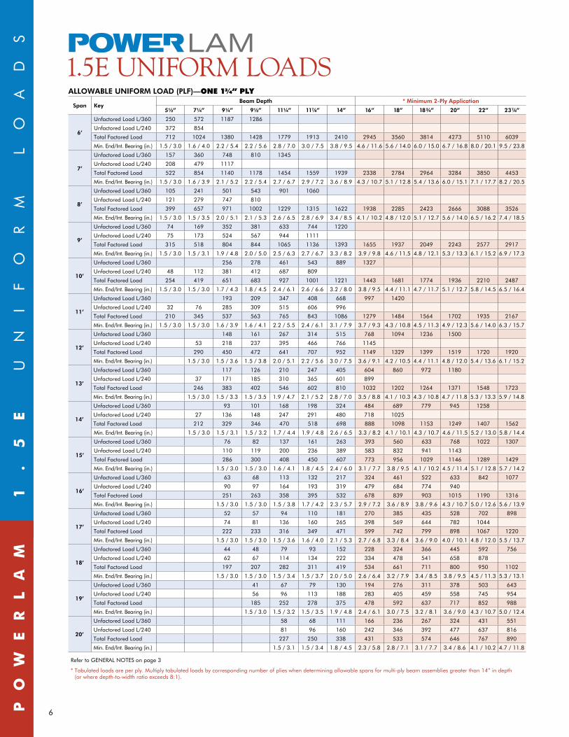
1.5e uniform LoaDS ALLOWABLE UnIfORM LOAD (PLf)—OnE 1¾” Ply
Span KeyBeam Depth * Minimum 2-Ply Application
5Z\x” 7Z\v” 9Z\v” 9Z\x” 11Z\v” 11M\,” 14” 16” 18” 18C\v” 20” 22” 23M\,”
6’
Unfactored Load L/360 250 572 1187 1286
Unfactored Load L/240 372 854
Total Factored Load 712 1024 1380 1428 1779 1913 2410 2945 3560 3814 4273 5110 6039
Min. End/Int. Bearing (in.) 1.5 / 3.0 1.6 / 4.0 2.2 / 5.4 2.2 / 5.6 2.8 / 7.0 3.0 / 7.5 3.8 / 9.5 4.6 / 11.6 5.6 / 14.0 6.0 / 15.0 6.7 / 16.8 8.0 / 20.1 9.5 / 23.8
7’
Unfactored Load L/360 157 360 748 810 1345
Unfactored Load L/240 208 479 1117
Total Factored Load 522 854 1140 1178 1454 1559 1939 2338 2784 2964 3284 3850 4453
Min. End/Int. Bearing (in.) 1.5 / 3.0 1.6 / 3.9 2.1 / 5.2 2.2 / 5.4 2.7 / 6.7 2.9 / 7.2 3.6 / 8.9 4.3 / 10.7 5.1 / 12.8 5.4 / 13.6 6.0 / 15.1 7.1 / 17.7 8.2 / 20.5
8’
Unfactored Load L/360 105 241 501 543 901 1060
Unfactored Load L/240 121 279 747 810
Total Factored Load 399 657 971 1002 1229 1315 1622 1938 2285 2423 2666 3088 3526
Min. End/Int. Bearing (in.) 1.5 / 3.0 1.5 / 3.5 2.0 / 5.1 2.1 / 5.3 2.6 / 6.5 2.8 / 6.9 3.4 / 8.5 4.1 / 10.2 4.8 / 12.0 5.1 / 12.7 5.6 / 14.0 6.5 / 16.2 7.4 / 18.5
9’
Unfactored Load L/360 74 169 352 381 633 744 1220
Unfactored Load L/240 75 173 524 567 944 1111
Total Factored Load 315 518 804 844 1065 1136 1393 1655 1937 2049 2243 2577 2917
Min. End/Int. Bearing (in.) 1.5 / 3.0 1.5 / 3.1 1.9 / 4.8 2.0 / 5.0 2.5 / 6.3 2.7 / 6.7 3.3 / 8.2 3.9 / 9.8 4.6 / 11.5 4.8 / 12.1 5.3 / 13.3 6.1 / 15.2 6.9 / 17.3
10’
Unfactored Load L/360 256 278 461 543 889 1327
Unfactored Load L/240 48 112 381 412 687 809
Total Factored Load 254 419 651 683 927 1001 1221 1443 1681 1774 1936 2210 2487
Min. End/Int. Bearing (in.) 1.5 / 3.0 1.5 / 3.0 1.7 / 4.3 1.8 / 4.5 2.4 / 6.1 2.6 / 6.6 3.2 / 8.0 3.8 / 9.5 4.4 / 11.1 4.7 / 11.7 5.1 / 12.7 5.8 / 14.5 6.5 / 16.4
11’
Unfactored Load L/360 193 209 347 408 668 997 1420
Unfactored Load L/240 32 76 285 309 515 606 996
Total Factored Load 210 345 537 563 765 843 1086 1279 1484 1564 1702 1935 2167
Min. End/Int. Bearing (in.) 1.5 / 3.0 1.5 / 3.0 1.6 / 3.9 1.6 / 4.1 2.2 / 5.5 2.4 / 6.1 3.1 / 7.9 3.7 / 9.3 4.3 / 10.8 4.5 / 11.3 4.9 / 12.3 5.6 / 14.0 6.3 / 15.7
12’
Unfactored Load L/360 148 161 267 314 515 768 1094 1236 1500
Unfactored Load L/240 53 218 237 395 466 766 1145
Total Factored Load 290 450 472 641 707 952 1149 1329 1399 1519 1720 1920
Min. End/Int. Bearing (in.) 1.5 / 3.0 1.5 / 3.6 1.5 / 3.8 2.0 / 5.1 2.2 / 5.6 3.0 / 7.5 3.6 / 9.1 4.2 / 10.5 4.4 / 11.1 4.8 / 12.0 5.4 / 13.6 6.1 / 15.2
13’
Unfactored Load L/360 117 126 210 247 405 604 860 972 1180
Unfactored Load L/240 37 171 185 310 365 601 899
Total Factored Load 246 383 402 546 602 810 1032 1202 1264 1371 1548 1723
Min. End/Int. Bearing (in.) 1.5 / 3.0 1.5 / 3.3 1.5 / 3.5 1.9 / 4.7 2.1 / 5.2 2.8 / 7.0 3.5 / 8.8 4.1 / 10.3 4.3 / 10.8 4.7 / 11.8 5.3 / 13.3 5.9 / 14.8
14’
Unfactored Load L/360 93 101 168 198 324 484 689 779 945 1258
Unfactored Load L/240 27 136 148 247 291 480 718 1025
Total Factored Load 212 329 346 470 518 698 888 1098 1153 1249 1407 1562
Min. End/Int. Bearing (in.) 1.5 / 3.0 1.5 / 3.1 1.5 / 3.2 1.7 / 4.4 1.9 / 4.8 2.6 / 6.5 3.3 / 8.2 4.1 / 10.1 4.3 / 10.7 4.6 / 11.5 5.2 / 13.0 5.8 / 14.4
15’
Unfactored Load L/360 76 82 137 161 263 393 560 633 768 1022 1307
Unfactored Load L/240 110 119 200 236 389 583 832 941 1143
Total Factored Load 286 300 408 450 607 773 956 1029 1146 1289 1429
Min. End/Int. Bearing (in.) 1.5 / 3.0 1.5 / 3.0 1.6 / 4.1 1.8 / 4.5 2.4 / 6.0 3.1 / 7.7 3.8 / 9.5 4.1 / 10.2 4.5 / 11.4 5.1 / 12.8 5.7 / 14.2
16’
Unfactored Load L/360 63 68 113 132 217 324 461 522 633 842 1077
Unfactored Load L/240 90 97 164 193 319 479 684 774 940
Total Factored Load 251 263 358 395 532 678 839 903 1015 1190 1316
Min. End/Int. Bearing (in.) 1.5 / 3.0 1.5 / 3.0 1.5 / 3.8 1.7 / 4.2 2.3 / 5.7 2.9 / 7.2 3.6 / 8.9 3.8 / 9.6 4.3 / 10.7 5.0 / 12.6 5.6 / 13.9
17’
Unfactored Load L/360 52 57 94 110 181 270 385 435 528 702 898
Unfactored Load L/240 74 81 136 160 265 398 569 644 782 1044
Total Factored Load 222 233 316 349 471 599 742 799 898 1067 1220
Min. End/Int. Bearing (in.) 1.5 / 3.0 1.5 / 3.0 1.5 / 3.6 1.6 / 4.0 2.1 / 5.3 2.7 / 6.8 3.3 / 8.4 3.6 / 9.0 4.0 / 10.1 4.8 / 12.0 5.5 / 13.7
18’
Unfactored Load L/360 44 48 79 93 152 228 324 366 445 592 756
Unfactored Load L/240 62 67 114 134 222 334 478 541 658 878
Total Factored Load 197 207 282 311 419 534 661 711 800 950 1102
Min. End/Int. Bearing (in.) 1.5 / 3.0 1.5 / 3.0 1.5 / 3.4 1.5 / 3.7 2.0 / 5.0 2.6 / 6.4 3.2 / 7.9 3.4 / 8.5 3.8 / 9.5 4.5 / 11.3 5.3 / 13.1
19’
Unfactored Load L/360 41 67 79 130 194 276 311 378 503 643
Unfactored Load L/240 56 96 113 188 283 405 459 558 745 954
Total Factored Load 185 252 278 375 478 592 637 717 852 988
Min. End/Int. Bearing (in.) 1.5 / 3.0 1.5 / 3.2 1.5 / 3.5 1.9 / 4.8 2.4 / 6.1 3.0 / 7.5 3.2 / 8.1 3.6 / 9.0 4.3 / 10.7 5.0 / 12.4
20’
Unfactored Load L/360 58 68 111 166 236 267 324 431 551
Unfactored Load L/240 81 96 160 242 346 392 477 637 816
Total Factored Load 227 250 338 431 533 574 646 767 890
Min. End/Int. Bearing (in.) 1.5 / 3.1 1.5 / 3.4 1.8 / 4.5 2.3 / 5.8 2.8 / 7.1 3.1 / 7.7 3.4 / 8.6 4.1 / 10.2 4.7 / 11.8
Refer to GEnERAL nOTES on page 3
* Tabulated loads are per ply. Multiply tabulated loads by corresponding number of plies when determining allowable spans for multi-ply beam assemblies greater than 14” in depth (or where depth-to-width ratio exceeds 8:1).
7
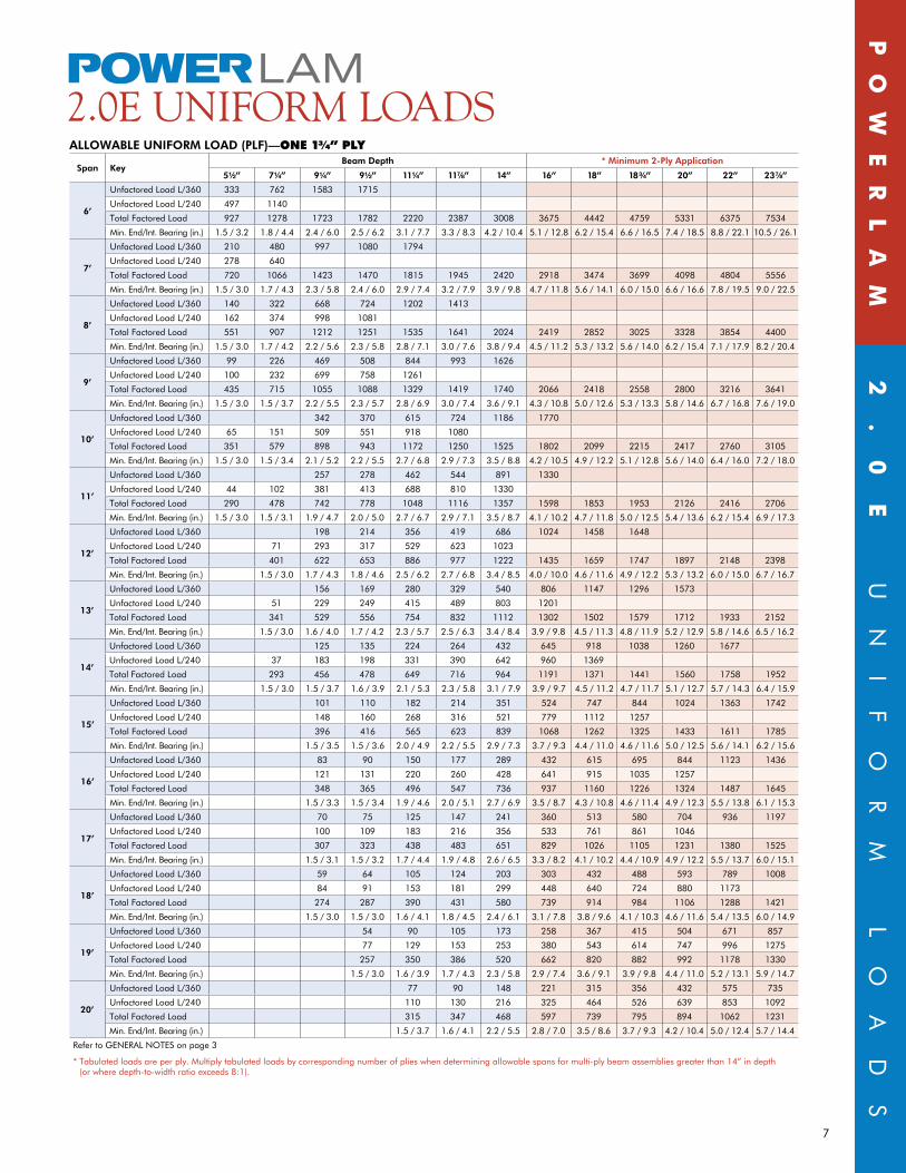
ALLOWABLE UnIfORM LOAD (PLf)—OnE 1¾” Ply
Span KeyBeam Depth * Minimum 2-Ply Application
5Z\x” 7Z\v” 9Z\v” 9Z\x” 11Z\v” 11M\,” 14” 16” 18” 18C\v” 20” 22” 23M\,”
6’
Unfactored Load L/360 333 762 1583 1715
Unfactored Load L/240 497 1140
Total Factored Load 927 1278 1723 1782 2220 2387 3008 3675 4442 4759 5331 6375 7534
Min. End/Int. Bearing (in.) 1.5 / 3.2 1.8 / 4.4 2.4 / 6.0 2.5 / 6.2 3.1 / 7.7 3.3 / 8.3 4.2 / 10.4 5.1 / 12.8 6.2 / 15.4 6.6 / 16.5 7.4 / 18.5 8.8 / 22.1 10.5 / 26.1
7’
Unfactored Load L/360 210 480 997 1080 1794
Unfactored Load L/240 278 640
Total Factored Load 720 1066 1423 1470 1815 1945 2420 2918 3474 3699 4098 4804 5556
Min. End/Int. Bearing (in.) 1.5 / 3.0 1.7 / 4.3 2.3 / 5.8 2.4 / 6.0 2.9 / 7.4 3.2 / 7.9 3.9 / 9.8 4.7 / 11.8 5.6 / 14.1 6.0 / 15.0 6.6 / 16.6 7.8 / 19.5 9.0 / 22.5
8’
Unfactored Load L/360 140 322 668 724 1202 1413
Unfactored Load L/240 162 374 998 1081
Total Factored Load 551 907 1212 1251 1535 1641 2024 2419 2852 3025 3328 3854 4400
Min. End/Int. Bearing (in.) 1.5 / 3.0 1.7 / 4.2 2.2 / 5.6 2.3 / 5.8 2.8 / 7.1 3.0 / 7.6 3.8 / 9.4 4.5 / 11.2 5.3 / 13.2 5.6 / 14.0 6.2 / 15.4 7.1 / 17.9 8.2 / 20.4
9’
Unfactored Load L/360 99 226 469 508 844 993 1626
Unfactored Load L/240 100 232 699 758 1261
Total Factored Load 435 715 1055 1088 1329 1419 1740 2066 2418 2558 2800 3216 3641
Min. End/Int. Bearing (in.) 1.5 / 3.0 1.5 / 3.7 2.2 / 5.5 2.3 / 5.7 2.8 / 6.9 3.0 / 7.4 3.6 / 9.1 4.3 / 10.8 5.0 / 12.6 5.3 / 13.3 5.8 / 14.6 6.7 / 16.8 7.6 / 19.0
10’
Unfactored Load L/360 342 370 615 724 1186 1770
Unfactored Load L/240 65 151 509 551 918 1080
Total Factored Load 351 579 898 943 1172 1250 1525 1802 2099 2215 2417 2760 3105
Min. End/Int. Bearing (in.) 1.5 / 3.0 1.5 / 3.4 2.1 / 5.2 2.2 / 5.5 2.7 / 6.8 2.9 / 7.3 3.5 / 8.8 4.2 / 10.5 4.9 / 12.2 5.1 / 12.8 5.6 / 14.0 6.4 / 16.0 7.2 / 18.0
11’
Unfactored Load L/360 257 278 462 544 891 1330
Unfactored Load L/240 44 102 381 413 688 810 1330
Total Factored Load 290 478 742 778 1048 1116 1357 1598 1853 1953 2126 2416 2706
Min. End/Int. Bearing (in.) 1.5 / 3.0 1.5 / 3.1 1.9 / 4.7 2.0 / 5.0 2.7 / 6.7 2.9 / 7.1 3.5 / 8.7 4.1 / 10.2 4.7 / 11.8 5.0 / 12.5 5.4 / 13.6 6.2 / 15.4 6.9 / 17.3
12’
Unfactored Load L/360 198 214 356 419 686 1024 1458 1648
Unfactored Load L/240 71 293 317 529 623 1023
Total Factored Load 401 622 653 886 977 1222 1435 1659 1747 1897 2148 2398
Min. End/Int. Bearing (in.) 1.5 / 3.0 1.7 / 4.3 1.8 / 4.6 2.5 / 6.2 2.7 / 6.8 3.4 / 8.5 4.0 / 10.0 4.6 / 11.6 4.9 / 12.2 5.3 / 13.2 6.0 / 15.0 6.7 / 16.7
13’
Unfactored Load L/360 156 169 280 329 540 806 1147 1296 1573
Unfactored Load L/240 51 229 249 415 489 803 1201
Total Factored Load 341 529 556 754 832 1112 1302 1502 1579 1712 1933 2152
Min. End/Int. Bearing (in.) 1.5 / 3.0 1.6 / 4.0 1.7 / 4.2 2.3 / 5.7 2.5 / 6.3 3.4 / 8.4 3.9 / 9.8 4.5 / 11.3 4.8 / 11.9 5.2 / 12.9 5.8 / 14.6 6.5 / 16.2
14’
Unfactored Load L/360 125 135 224 264 432 645 918 1038 1260 1677
Unfactored Load L/240 37 183 198 331 390 642 960 1369
Total Factored Load 293 456 478 649 716 964 1191 1371 1441 1560 1758 1952
Min. End/Int. Bearing (in.) 1.5 / 3.0 1.5 / 3.7 1.6 / 3.9 2.1 / 5.3 2.3 / 5.8 3.1 / 7.9 3.9 / 9.7 4.5 / 11.2 4.7 / 11.7 5.1 / 12.7 5.7 / 14.3 6.4 / 15.9
15’
Unfactored Load L/360 101 110 182 214 351 524 747 844 1024 1363 1742
Unfactored Load L/240 148 160 268 316 521 779 1112 1257
Total Factored Load 396 416 565 623 839 1068 1262 1325 1433 1611 1785
Min. End/Int. Bearing (in.) 1.5 / 3.5 1.5 / 3.6 2.0 / 4.9 2.2 / 5.5 2.9 / 7.3 3.7 / 9.3 4.4 / 11.0 4.6 / 11.6 5.0 / 12.5 5.6 / 14.1 6.2 / 15.6
16’
Unfactored Load L/360 83 90 150 177 289 432 615 695 844 1123 1436
Unfactored Load L/240 121 131 220 260 428 641 915 1035 1257
Total Factored Load 348 365 496 547 736 937 1160 1226 1324 1487 1645
Min. End/Int. Bearing (in.) 1.5 / 3.3 1.5 / 3.4 1.9 / 4.6 2.0 / 5.1 2.7 / 6.9 3.5 / 8.7 4.3 / 10.8 4.6 / 11.4 4.9 / 12.3 5.5 / 13.8 6.1 / 15.3
17’
Unfactored Load L/360 70 75 125 147 241 360 513 580 704 936 1197
Unfactored Load L/240 100 109 183 216 356 533 761 861 1046
Total Factored Load 307 323 438 483 651 829 1026 1105 1231 1380 1525
Min. End/Int. Bearing (in.) 1.5 / 3.1 1.5 / 3.2 1.7 / 4.4 1.9 / 4.8 2.6 / 6.5 3.3 / 8.2 4.1 / 10.2 4.4 / 10.9 4.9 / 12.2 5.5 / 13.7 6.0 / 15.1
18’
Unfactored Load L/360 59 64 105 124 203 303 432 488 593 789 1008
Unfactored Load L/240 84 91 153 181 299 448 640 724 880 1173
Total Factored Load 274 287 390 431 580 739 914 984 1106 1288 1421
Min. End/Int. Bearing (in.) 1.5 / 3.0 1.5 / 3.0 1.6 / 4.1 1.8 / 4.5 2.4 / 6.1 3.1 / 7.8 3.8 / 9.6 4.1 / 10.3 4.6 / 11.6 5.4 / 13.5 6.0 / 14.9
19’
Unfactored Load L/360 54 90 105 173 258 367 415 504 671 857
Unfactored Load L/240 77 129 153 253 380 543 614 747 996 1275
Total Factored Load 257 350 386 520 662 820 882 992 1178 1330
Min. End/Int. Bearing (in.) 1.5 / 3.0 1.6 / 3.9 1.7 / 4.3 2.3 / 5.8 2.9 / 7.4 3.6 / 9.1 3.9 / 9.8 4.4 / 11.0 5.2 / 13.1 5.9 / 14.7
20’
Unfactored Load L/360 77 90 148 221 315 356 432 575 735
Unfactored Load L/240 110 130 216 325 464 526 639 853 1092
Total Factored Load 315 347 468 597 739 795 894 1062 1231
Min. End/Int. Bearing (in.) 1.5 / 3.7 1.6 / 4.1 2.2 / 5.5 2.8 / 7.0 3.5 / 8.6 3.7 / 9.3 4.2 / 10.4 5.0 / 12.4 5.7 / 14.4
Refer to GEnERAL nOTES on page 3
* Tabulated loads are per ply. Multiply tabulated loads by corresponding number of plies when determining allowable spans for multi-ply beam assemblies greater than 14” in depth (or where depth-to-width ratio exceeds 8:1).
Po
We
RL
AM
2.
0e
U
nI
FO
RM
L
OA
dS
2.0e uniform LoaDS
8
muLtiPLe-PLy beam aSSembLy
Po
We
RL
AM
MU
LT
IP
LE
-P
LY
B
EA
M
AS
SE
MB
LY
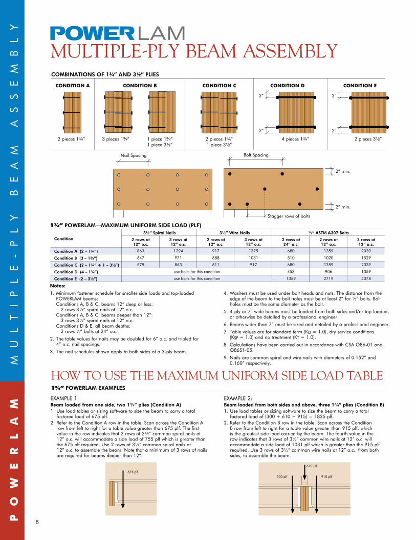
ExAMPLE 1:Beam loaded from one side, two 1¾” plies (Condition A)1. Useloadtablesorsizingsoftwaretosizethebeamtocarryatotal
factored load of 675 plf.2. Refer to the Condition A row in the table. Scan across the Condition A
row from left to right for a table value greater than 675 plf. The first value in the row indicates that 2 rows of 3½” common spiral nails at 12” o.c. will accommodate a side load of 755 plf which is greater than the 675 plf required. Use 2 rows of 3½” common spiral nails at 12” o.c. to assemble the beam. note that a minimum of 3 rows of nails are required for beams deeper than 12”.
ExAMPLE 2:Beam loaded from both sides and above, three 1¾” plies (Condition B)1. Useloadtablesorsizingsoftwaretosizethebeamtocarryatotal
factored load of (300 + 610 + 915) = 1825 plf.2. Refer to the Condition B row in the table. Scan across the Condition
B row from left to right for a table value greater than 915 plf, which is the greatest side load carried by the beam. The fourth value in the row indicates that 3 rows of 3½” common wire nails at 12” o.c. will accommodate a side load of 1031 plf which is greater than the 915 plf required. Use 3 rows of 3½” common wire nails at 12” o.c., from both sides, to assemble the beam.
915 plf
610 plf
300 plf
1¾” POWERLAM ExAMPLES
675 plf
COMBInATIOnS Of 1C\v” AnD 3Z\x” PLIES
How to uSe tHe maximum uniform SiDe LoaD tabLe
1¾” POWERLAM—MAxIMUM UnIfORM SIDE LOAD (PLf)
Condition3½” Spiral nails 3½” Wire nails ½” ASTM A307 Bolts
2 rows at 12” o.c.
3 rows at 12” o.c.
2 rows at 12” o.c.
3 rows at 12” o.c.
2 rows at 24” o.c.
2 rows at 12” o.c.
3 rows at 12” o.c.
Condition A (2 – 1C\v”) 863 1294 917 1375 680 1359 2039
Condition B (3 – 1C\v”) 647 971 688 1031 510 1020 1529
Condition C (2 – 1C\v” + 1 – 3Z\x”) 575 863 611 917 680 1359 2039
Condition D (4 – 1C\v”) use bolts for this condition 453 906 1359
Condition E (2 – 3Z\x”) use bolts for this condition 1359 2719 4078
2 pieces 1C\v” 2 pieces 1C\v”1 piece 3Z\x”
4 pieces 1C\v”
2”
2”
3 pieces 1C\v” 1 piece 1C\v”1 piece 3Z\x”
nail Spacing
2”
2 pieces 3Z\x”
2”
Bolt Spacing
2” min.
2” min.
Stagger rows of bolts
condition A condition b condition c condition d condition e
2 pieces 1C\v” 3 pieces 1C\v” 4 pieces 1C\v” 2 pieces 3Z\x” 1 piece 1C\v”
1 piece 3Z\x” 2 pieces 1C\v”
1 piece 3Z\x”
notes:
1. Minimum fastener schedule for smaller side loads and top-loaded POWERLAM beams:
Conditions A, B & C, beams 12” deep or less: 2 rows 3½” spiral nails at 12” o.c. Conditions A, B & C, beams deeper than 12”: 3 rows 3½” spiral nails at 12” o.c. Conditions d & E, all beam depths: 2 rows Z\x” bolts at 24” o.c.
2. The table values for nails may be doubled for 6” o.c. and tripled for 4” o.c. nail spacings.
3. The nail schedules shown apply to both sides of a 3-ply beam.
4. Washers must be used under bolt heads and nuts. The distance from the edge of the beam to the bolt holes must be at least 2” for ½” bolts. Bolt holes must be the same diameter as the bolt.
5. 4-ply or 7” wide beams must be loaded from both sides and/or top loaded, or otherwise be detailed by a professional engineer.
6. Beamswiderthan7”mustbesizedanddetailedbyaprofessionalengineer.
7. Tablevaluesareforstandardterm(Kd = 1.0), dry service conditions (KSF=1.0)andnotreatment(KT = 1.0).
8. Calculations have been carried out in accordance with CSA O86-01 and O86S1-05.
9. nails are common spiral and wire nails with diameters of 0.152” and 0.160” respectively.
9
The properties that make POWERLAM a superior beam material make it ideal for column use as well. In POWERLAM columns, you’ll find only quality construction, free of deep cracks, checks or twists. These columns are desirable enough to leave exposed, for a beautiful finish.
2.0e CoLumnS
POWERLAM COLUMnS—fACTORED RESISTAnCE [LBS]
Length1.5E grade 2.0E grade
3½” x 3½” 3½” x 5½” 3½” x 7¼” 3½” x 3½” 3½” x 5½” 3½” x 7¼”
6’ 11260 17690 23320 15440 24270 31990
7’ 9670 15200 20040 13220 20770 27380
8’ 8240 12950 17070 11220 17630 23240
9’ 6980 10980 14470 9480 14900 19650
10’ 5910 9290 12240 8010 12580 16580
11’ 5000 7860 10360 6760 10620 14000
12’ 4240 6660 8770 5720 8980 11840
13’ 3600 5650 7450 4840 7610 10030
14’ 3060 4810 6340 4120 6470 8530
> 14’ not Permitted not Permitted
1. Table values apply to solid, one-piece columns with an effective length equal to the actual column length.2.Tablevaluesareforstandardterm(Kd=1.0),dryserviceconditions(KS=1.0)andnotreatment(KT = 1.0).3. Table values apply to axially-loaded columns. A load eccentricity equal to the worst case of one-sixth of either column dimension is assumed.
Refer to CSA-O86 when designing for combined bending and axial loads or other load eccentricities.4. Calculations have been carried out in accordance with CSA O86-01, O86S1-05 and the 2005 nBCC
POWERLAM nAILED, BUILT-UP COLUMnS—fACTORED RESISTAnCE [LBS]
Length
1.5E grade 2.0E grade
2-Ply 1½” x 2-Ply 1¾” x 2-Ply 1½” x 2-Ply 1¾” x
3½” 5½” 7¼” 3½” 5½” 7¼” 3½” 5½” 7¼” 3½” 5½” 7¼”
6’ 5020 7890 10410 6750 10610 13990 6860 10790 14220 9270 14560 19190
7’ 4160 6530 8610 5800 9120 12020 5660 8890 11720 7930 12460 16430
8’ 3420 5380 7090 4940 7770 10240 4640 7300 9620 6730 10580 13950
9’ 2810 4420 5830 4190 6590 8680 3810 5980 7890 5690 8940 11790
10’ 2310 3640 4790 3550 5570 7350 3130 4910 6470 4800 7550 9950
11’ 1910 3000 3950 3000 4710 6220 2570 4040 5330 4060 6370 8400
12’ 1580 2480 3270 2540 3990 5260 2130 3340 4400 3430 5390 7100
13’
not Permitted
2160 3390 4470
not Permitted
2910 4570 6020
14’ 1840 2880 3800 2470 3880 5120
> 14’ not Permitted not Permitted
1. Table values apply to solid, one-piece columns with an effective length equal to the actual column length.2.Tablevaluesareforstandardterm(Kd=1.0),dryserviceconditions(KS=1.0)andnotreatment(KT = 1.0).3. Table values apply to axially-loaded columns. A load eccentricity equal to the worst case of one-sixth of either column dimension is assumed.
Refer to CSA-O86 when designing for combined bending and axial loads or other load eccentricities.4. Calculations have been carried out in accordance with CSA O86-01, O86S1-05 and the 2005 nBCC
nAIL SCHEDULE
1½” Plies 1¾” Plies
2” minimum length 3” minimum length
9” maximum spacing along column 10½” maximum spacing along column
One row for 3½” wide plies One row for 3½” wide plies
Two rows for 5½” & 7¼” wide plies Two rows for 5½” & 7¼” wide plies
Maximum row spacing = 20 nail diameters Maximum row spacing = 20 nail diameters
Alternate from face to face when driving nails Alternate from face to face when driving nails
CoLumn LoaD tabLeS
Po
We
RL
AM
2.
0e
C
OL
UM
nS

10
Po
We
RL
AM
BE
AR
In
G
LE
nG
TH
R
Eq
UI
RE
ME
nT
S
POWERLAM BEARIng LEngTH REqUIREMEnTS(1)(2)(3)(4)(5)
Support Material S-P-f(6) Douglas
fir – Larch(6) northern Species(6) 1.5E POWERLAM(7) 2.0E POWERLAM(7)
factored Resistance 615 psi 812 psi 406 psi 1092 psi (edge bearing) 1238 psi (edge bearing)
number of 1¾” LVL Plies 1-Ply 2-Ply 3-Ply 4-Ply 1-Ply 2-Ply 3-Ply 4-Ply 1-Ply 2-Ply 3-Ply 4-Ply 1-Ply 2-Ply 3-Ply 4-Ply 1-Ply 2-Ply 3-Ply 4-Ply
fact
ore
d R
eact
ion
(x
1000 l
bs)
1 1½” 1½” 1½” 1½” 1½” 1½” 1½” 1½” 1½” 1½” 1½” 1½” 1½” 1½” 1½” 1½” 1½” 1½” 1½” 1½”
2 2” 1½” 1½” 1½” 1½” 1½” 1½” 1½” 3” 1½” 1½” 1½” 1½” 1½” 1½” 1½” 1½” 1½” 1½” 1½”
3 3” 1½” 1½” 1½” 2¼” 1½” 1½” 1½” 4¼” 2¼” 1½” 1½” 1¾” 1½” 1½” 1½” 1½” 1½” 1½” 1½”
4 3¾” 2” 1½” 1½” 3” 1½” 1½” 1½” 5¾” 3” 2” 1½” 2¼” 1½” 1½” 1½” 2” 1½” 1½” 1½”
5 4¾” 2½” 1¾” 1½” 3¾” 2” 1½” 1½” 7¼” 3¾” 2½” 2” 2¾” 1½” 1½” 1½” 2½” 1½” 1½” 1½”
6 5¾” 3” 2” 1½” 4¼” 2¼” 1½” 1½” 8½” 4¼” 3” 2¼” 3¼” 1¾” 1½” 1½” 3” 1½” 1½” 1½”
7 6¾” 3½” 2¼” 1¾” 5” 2½” 1¾” 1½” 10” 5” 3½” 2½” 3¾” 2” 1½” 1½” 3¼” 1¾” 1½” 1½”
8 7½” 3¾” 2½” 2” 5¾” 3” 2” 1½” 5¾” 4” 3” 4¼” 2¼” 1½” 1½” 3¾” 2” 1½” 1½”
9 8½” 4¼” 3” 2¼” 6½” 3¼” 2¼” 1¾” 6½” 4¼” 3¼” 4¾” 2½” 1¾” 1½” 4¼” 2¼” 1½” 1½”
10 9½” 4¾” 3¼” 2½” 7¼” 3¾” 2½” 2” 7¼” 4¾” 3¾” 5¼” 2¾” 1¾” 1½” 4¾” 2½” 1¾” 1½”
11 10¼” 5¼” 3½” 2¾” 7¾” 4” 2¾” 2” 7¾” 5¼” 4” 6” 3” 2” 1½” 5¼” 2¾” 1¾” 1½”
12 11¼” 5¾” 3¾” 3” 8½” 4¼” 3” 2¼” 8½” 5¾” 4¼” 6½” 3¼” 2¼” 1¾” 5¾” 3” 2” 1½”
13 6¼” 4¼” 3¼” 9¼” 4¾” 3¼” 2½” 9¼” 6¼” 4¾” 7” 3½” 2½” 1¾” 6¼” 3¼” 2¼” 1¾”
14 6¾” 4½” 3½” 10” 5” 3½” 2½” 10” 6¾” 5” 7½” 3¾” 2½” 2” 6½” 3¼” 2¼” 1¾”
15 7” 4¾” 3½” 10¾” 5½” 3¾” 2¾” 10¾” 7¼” 5½” 8” 4” 2¾” 2” 7” 3½” 2½” 1¾”
16 7½” 5” 3¾” 5¾” 4” 3” 7¾” 5¾” 8½” 4¼” 3” 2¼” 7½” 3¾” 2½” 2”
17 8” 5½” 4” 6” 4” 3” 8” 6” 9” 4½” 3” 2¼” 8” 4” 2¾” 2”
18 8½” 5¾” 4¼” 6½” 4¼” 3¼” 8½” 6½” 9½” 4¾” 3¼” 2½” 8½” 4¼” 3” 2¼”
19 9” 6” 4½” 6¾” 4½” 3½” 9” 6¾” 10” 5” 3½” 2½” 9” 4½” 3” 2¼”
20 9½” 6¼” 4¾” 7¼” 4¾” 3¾” 9½” 7¼” 10½” 5¼” 3½” 2¾” 9¼” 4¾” 3¼” 2½”
21 10” 6¾” 5” 7½” 5” 3¾” 10” 7½” 11” 5½” 3¾” 2¾” 9¾” 5” 3¼” 2½”
22 10¼” 7” 5¼” 7¾” 5¼” 4” 10½” 7¾” 11¾” 6” 4” 3” 10¼” 5¼” 3½” 2¾”
23 10¾” 7¼” 5½” 8¼” 5½” 4¼” 11” 8¼” 12¼” 6¼” 4¼” 3¼” 10¾” 5½” 3¾” 2¾”
24 11¼” 7½” 5¾” 8½” 5¾” 4¼” 8½” 12¾” 6½” 4¼” 3¼” 11¼” 5¾” 3¾” 3”
25 7¾” 6” 9” 6” 4½” 9” 6¾” 4½” 3½” 11¾” 6” 4” 3”
26 8¼” 6¼” 9¼” 6¼” 4¾” 9¼” 7” 4¾” 3½” 12¼” 6¼” 4¼” 3¼”
27 8½” 6½” 9¾” 6½” 5” 9¾” 7¼” 4¾” 3¾” 12½” 6¼” 4¼” 3¼”
28 8¾” 6¾” 10” 6¾” 5” 10” 7½” 5” 3¾” 13” 6½” 4½” 3¼”
29 9” 6¾” 10¼” 7” 5¼” 10¼” 7¾” 5¼” 4” 6¾” 4½” 3½”
30 9½” 7” 10¾” 7¼” 5½” 10¾” 8” 5¼” 4” 7” 4¾” 3½”
31 9¾” 7¼” 11” 7½” 5½” 11” 8¼” 5½” 4¼” 7¼” 5” 3¾”
32 10” 7½” 7¾” 5¾” 8½” 5¾” 4¼” 7½” 5” 3¾”
33 10¼” 7¾” 7¾” 6” 8¾” 6” 4½” 7¾” 5¼” 4”
34 10¾” 8” 8” 6” 9” 6” 4½” 8” 5¼” 4”
35 11” 8¼” 8¼” 6¼” 9¼” 6¼” 4¾” 8¼” 5½” 4¼”
36 11¼” 8½” 8½” 6½” 9½” 6½” 4¾” 8½” 5¾” 4¼”
37 8¾” 8¾” 6¾” 9¾” 6½” 5” 8¾” 5¾” 4½”
38 9” 9” 6¾” 10” 6¾” 5” 9” 6” 4½”
notes:1. Tablevaluesareforstandardterm(Kd=1.0, no adjustment permitted,
dryserviceconditions(KSCP=1.0),andnotreatment(KT=1.0)2. The minimum required bearing length is 1Z\x”.3. All beams require support across their full width and lateral support at
bearing points.4.Thesupportmembermustbesizedtocarrytheloadfromthebeam.5. Calculations have been carried out in accordance with CSA O86-01,
O86S1-05, and the 2005 nBCC.
6. Use these values when the beam is supported by a wall plate, sill plate, timber, or built-up girder.
7. Use these values when the beam is supported by the end of a column or connection hardware.
1¾” PLieSbearing LengtH requirementS
11
Po
We
RL
AM
BE
AR
In
G
An
d
HO
LE
d
ET
AI
LS
¹⁄₃ Span¹⁄₄ Span
See note 4
¹⁄₃ Depth
¹⁄₃ Depth
¹⁄₃ Depth
End Support Interior Support
bearing DetaiLS
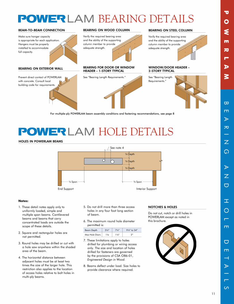
For multiple-ply POWERLAM beam assembly conditions and fastening recommendations, see page 8
BEAM-TO-BEAM COnnECTIOn
Make sure hanger capacity is appropriate for each application. Hangers must be properly installed to accommodate full capacity.
BEARIng On STEEL COLUMn
Verify the required bearing area and the ability of the supporting column member to provide adequate strength.
BEARIng On ExTERIOR WALL
Prevent direct contact of POWERLAM with concrete. Consult local building code for requirements.
BEARIng On WOOD COLUMn
Verify the required bearing area and the ability of the supporting column member to provide adequate strength.
BEARIng fOR DOOR OR WInDOW HEADER – 1-STORy TyPICAL
See “Bearing Length Requirements.”
WInDOW/DOOR HEADER – 2-STORy TyPICAL
See “Bearing Length Requirements.”
HoLe DetaiLSHOLES In POWERLAM BEAMS
notes:
1. These detail notes apply only to uniformly loaded, simple and multiple span beams. Cantilevered beams and beams that carry concentrated loads are outside the scope of these details.
2. Square and rectangular holes are not permitted.
3. Round holes may be drilled or cut with a hole saw anywhere within the shaded area of the beam.
4.Thehorizontaldistancebetweenadjacent holes must be at least two timesthesizeofthelargerhole.Thisrestriction also applies to the location of access holes relative to bolt holes in multi-ply beams.
5. do not drill more than three access holes in any four foot long section of beam.
6. The maximum round hole diameter permitted is:
Beam depth 5Z\x” 7Z\v” 9Z\x” to 24”
Max Hole diam. 1Z\, 1Z\x” 2”
7. These limitations apply to holes drilled for plumbing or wiring access only.Thesizeandlocationofholesdrilled for fasteners are governed by the provisions of CSA O86-01, EngineeredDesigninWood.
8.Beamsdeflectunderload.Sizeholestoprovide clearance where required.
nOTCHES & HOLES
do not cut, notch or drill holes in POWERLAM except as noted in this brochure.

SALES OFFICE 106 Saunders Rd., Unit 12
Barrie, On L4n 9A8(705) 733-3843 local
(888) 262-2524 toll free(705) 733-3718 fax
MAnUFACTURInG FACILITY2 Greengage Road
new Lowell, On L0M 1n0(705) 424-3905 local(705) 424-4305 fax
www.phoenixbuilding.caPrinted in Canada 080608
PHoenixbuiLDing
ComPonentS
Dedicated to bui lding a s t rong future—inherent in our qual i ty products ,
and our s t rong commitment to value creat ion for both our employees and customers .