Embed Size (px)
Citation preview

1
Beamforming with Optimal Aliasing Cancellation inSpherical Microphone Arrays
David Lou Alon, Member, IEEE, Boaz Rafaely, Senior Member, IEEE
Abstract—Spherical microphone arrays facilitate three-dimensional processing and analysis of sound fields in applica-tions such as music recording, beamforming and room acoustics.The frequency bandwidth of operation is constrained by the arrayconfiguration. At high frequencies, spatial aliasing leads to side-lobes in the array beam pattern, which limits array performance.Previous studies proposed increasing the number of microphonesor changing other characteristics of the array configuration toreduce the effect of aliasing. In this paper we present a method todesign beamformers that overcome the effect of spatial aliasingby suppressing the undesired side-lobes through signal processingwithout physically modifying the configuration of the array.This is achieved by modeling the expected aliasing pattern ina maximum-directivity beamformer design, leading to a higherdirectivity index at frequencies previously considered to be outof the operating bandwidth, thereby extending the microphonearray frequency range of operation. Aliasing cancellation is thenextended to other beamformers. A simulation example with a 32-element spherical microphone array illustrates the performanceof the proposed method. An experimental example validates thetheoretical results in practice.
Index Terms—Array processing, aliasing cancellation, beam-forming, directivity, maximum-directiviy beamformer, optimalbeamformer, spherical microphone arrays, spherical harmonics,spatial aliasing, white-noise gain.
I. INTRODUCTION
SPHERICAL microphone arrays, composed of micro-phones arranged on the surface of a sphere, have been
studied extensively in the past decade. The spherical symmetryfacilitates steering of the directional beam pattern over theentire directional space. This was found to be useful forvarious applications such as music recording, beamforming[2], [3], and sound field analysis [4], [5]. By decomposing thesound field into spherical harmonics (SH) [6], [7], Rafaely [8]presented a performance analysis that specifies the limitationsof the spherical microphone array operating bandwidth. Atlow frequencies, a trade-off between array robustness andspatial resolution leads to limitations in array performance [2],[5]. As the frequency increases, the function representing thesound field pressure around the sphere is of higher order. Thisorder may be higher than the maximum order of the array, asdetermined by the number of microphones, leading to spatialaliasing [7]. Spatial aliasing and the formation of undesiredside-lobes in the microphone array directional beam pattern are
Manuscript received May 13, 2015; revised Octoer 22, 2015; acceptedNovember 9, 2015. This work was supported by the European Union’s SeventhFramework Programme (FP7/2007-2013) under grant agreement no. 609465
D. L. Alon and B. Rafaely are with the Department of Electrical andComputer Engineering, Ben-Gurion University of the Negev, Beer-Sheva84105, Israel (e-mail: [email protected], [email protected]).
Parts of this work have been previously presented in reference [1] .
the dominant reasons for performance degradation at high fre-quency [4]. Some methods previously presented that attemptto reduce aliasing [9], [10] work well, but only for sound fieldswith specific characteristics. Other methods that tend to reducethe level of the side-lobes, also known as grating-lobes, werepreviously presented. These include increasing the numberof microphones; limiting the allowable steering angle [11];incorporating microphones with large membranes [2], or otherforms of directional microphones [12], [13], [14]; or usingirregular sampling [15]. The shortcoming of these methods isthat they involve physical changes to the microphone array.
A new method for designing a beamformer which eliminatesthe negative effect of spatial aliasing is presented in this paper.The new method is developed assuming a general sound fieldand without requiring physical modification of the microphonearray. This method is based on an aliasing projection matrixin the SH domain [12], [16], [17], which facilitates analysisof the aliasing pattern, i.e. the way in which high SH ordersare aliased into lower orders. The aliasing projection matrixis utilized to develop a new beamforming equation that in-corporates information about spatial aliasing. Using the newbeamforming equation, a formulation of a new maximum-directivity (MD) beamformer that minimizes the aliasing is de-veloped, and is referred to as a maximum-directivity aliasing-cancellation (MDAC) beamformer. The MDAC beamformerdesign is followed by a design for maximum white noisegain (WNG) and a least-squares (LS) based design, both withaliasing cancellation.
The advantage and novelty of the proposed method is thataliasing cancellation is achieved solely through array signalprocessing, with respect to the given array sampling scheme,and can therefore be applied to any existing spherical array.The beamformer achieves high directivity at frequencies previ-ously considered to be out of the microphone array operatingrange and, therefore, increases the overall frequency range ofoperation.
The proposed method is based on aliasing cancellation,previously presented for spherical arrays [1] and for circulararrays [18]. In this paper a more detailed formulation of thenovel aliasing-cancellation method is presented, including per-formance and robustness analyses and a more comprehensivesimulation study. Moreover, the design of other beamformerswith aliasing cancellation, such as minimum-variance distor-tionless response (MVDR), maximum WNG and LS baseddesign, is also presented. In addition, an experimental inves-tigation using a real microphone array system is presented,providing validation of the new method’s performance.
This paper is organized as follows. Section II reviews the

2
theory of spherical microphone array processing. Section IIIpresents a matrix formulation that describes how high soundfield orders are aliased into the lower microphone array orders.In sections IV and V the proposed method for designingan aliasing-cancellation beamformers is developed. A detailedsimulation study and a validation experiment are then givenin sections VI, VII and VIII. Section IX concludes the paper.
II. SPHERICAL MICROPHONE ARRAY PROCESSING
The theory of spherical microphone array processing isbriefly revised in this section. The formulation provided inthis section will be used in the following sections to developthe aliasing-cancellation beamformer.
A. Array Equation in the SH Domain
Consider the sound pressure due to a unit-amplitude incidentplane-wave, arriving from direction (θ0, φ0) with wave numberk. The pressure is measured at (r, θ, φ), which is the spatiallocation of a microphone in the standard spherical coordinatesystem[19]. Using SH, the pressure can be written as [6]
p0 (k, r, θ, φ) =
∞∑n=0
n∑m=−n
[Y mn (θ0, φ0)]∗bn (kr)Y mn (θ, φ),
(1)where Y mn (θ, φ) is the SH function of order n and degree m[19], and bn (kr) is the mode strength generalized for variousarray configurations (such as an array configured around arigid sphere, which is assumed for this paper [20]). For themore general case, where the sound field is composed of aninfinite number of plane-waves with plane-wave amplitudedensity a (k, θ, φ), the pressure can be written as [8]
p (k, r, θ, φ) =∞∑n=0
n∑m=−n
anm (k) bn (kr)Y mn (θ, φ), (2)
where anm (k) is the spherical Fourier transform of a (k, θ, φ).Using the spherical Fourier transform of the measured pressurep (k, r, θ, φ), the pressure coefficients pnm can be computedfrom the expression
pnm (k, r) = anm (k) bn (kr) . (3)
At low frequencies, higher orders of mode strength bn (kr) areextremely small and, therefore, can be neglected. For operatingfrequencies that satisfy kr ≤ N the measured pressure can beapproximated as order limited, meaning pnm = 0 ∀n > N [8].In this case the infinite summation in (2) can be replaced witha finite summation over n up to order N ,
p (k, r, θ, φ) =N∑n=0
n∑m=−n
anm (k) bn (kr)Y mn (θ, φ). (4)
The (N + 1)2 pressure coefficients pnm can hence be calcu-
lated by approximating the spherical Fourier transform by afinite summation over spatial samples on the sphere. Usinga spherical microphone array with microphones located at(r, θj , φj), 1 ≤ j ≤M , the pressure is sampled at M spatialpositions. Dividing the approximated pressure coefficients
pnm by bn (kr) gives us an estimated value of the plane-wave amplitude coefficients. This is referred to as plane-wavedecomposition [21],
anm (k) =M∑j=1
αj (k)
bn (k, r)[Y mn (θj , φj)]
∗p (k, r, θj , φj) , (5)
where the weighting parameters αj (k) are introduced toapproximate the spherical Fourier integral with a summationover the positions (r, θj , φj), and the values of αj (k) are de-termined by the sampling scheme. Several sampling schemesthat offer a trade-off between the total number of samplingpoints and the complexity of the scheme have been previouslypresented [22], [23], [4]. The advantage of sampling schemessuch as the equal-angle, Gaussian and uniform is that αj (k)can be calculated analytically [4]. When using other samplingschemes, the weighting parameters αj (k) may need to becalculated numerically. Defining a new set of coefficients, cjnm,replacing αj (k) [Y mn (θj , φj)]
∗/bn (k, r) in equation (5) ,we
get a new expression for the plane-wave decomposition:
anm (k) =M∑j=1
cjnm (k) p (k, rj , θj , φj) . (6)
Using the plane-wave decomposition result in (6), which isrepresented in the SH domain, the array output y (k) can nowbe computed using beamforming formulated in the SH domainas
y (k) =N∑n=0
n∑m=−n
d∗nm (θl, φl) anm (k) , (7)
where the beamformer coefficients dnm (θl, φl) control thebeam pattern, which has a desired look direction denotedby (θl, φl). Different beam patterns can be designed us-ing different sets of beamforming coefficients. Such beam-forming coefficients may include the axis-symmetric modalbeamformer with dnm = dnY
m∗n (θl, φl) [2]; the maximum
WNG beamformer with dnm = |bn (kr)|2 Y m∗n (θl, φl) [24];or the MD beamformer, also referred to as the plane-wavedecomposition beamformer, with dnm = 4π
(N+1)2Y m∗n (θl, φl)
[25]. These beamformers work well at frequencies that satisfykr ≤ N , where the small contribution of higher sound fieldorders can be neglected. However, at higher frequencies theenergy of higher orders increases and the performance of thesebeamformers deteriorates due to spatial aliasing. Improving theperformance of beamformers at high frequencies is the maingoal of this paper.
The beamforming equation (7) in the SH domain can alsobe written in the more standard spatial domain as a weightedsum of the pressure, which is spatially sampled by the arrayand is given by [26]
y (k) =M∑j=1
w∗j (k) p (k, rj , θj , φj) , (8)
where the weights w∗j (k) operate as a spatialfilter or beamformer. This defines the arrayequation in the space domain. Using the relationw∗j (k) =
∑Nn=0
∑nm=−n d
∗nm (θl, φl) c
jnm (k), beamformers
3
designed in the SH domain can be easily applied in thespace domain. A comparison between space domain and SHdomain processing is presented in the following sections.
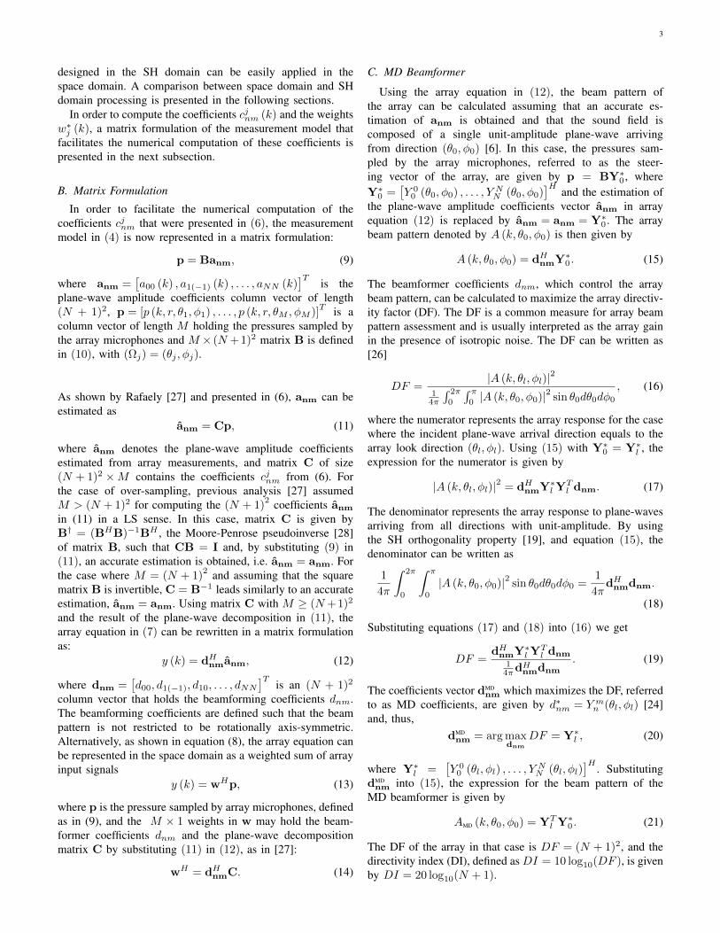
In order to compute the coefficients cjnm (k) and the weightsw∗j (k), a matrix formulation of the measurement model thatfacilitates the numerical computation of these coefficients ispresented in the next subsection.
B. Matrix Formulation
In order to facilitate the numerical computation of thecoefficients cjnm that were presented in (6), the measurementmodel in (4) is now represented in a matrix formulation:
p = Banm, (9)
where anm =[a00 (k) , a1(−1) (k) , . . . , aNN (k)
]Tis the
plane-wave amplitude coefficients column vector of length(N + 1)2, p = [p (k, r, θ1, φ1) , . . . , p (k, r, θM , φM )]
T is acolumn vector of length M holding the pressures sampled bythe array microphones and M × (N + 1)2 matrix B is definedin (10), with (Ωj) = (θj , φj).
As shown by Rafaely [27] and presented in (6), anm can beestimated as
anm = Cp, (11)
where anm denotes the plane-wave amplitude coefficientsestimated from array measurements, and matrix C of size(N + 1)2 ×M contains the coefficients cjnm from (6). Forthe case of over-sampling, previous analysis [27] assumedM > (N + 1)2 for computing the (N + 1)
2 coefficients anm
in (11) in a LS sense. In this case, matrix C is given byB† = (BHB)−1BH , the Moore-Penrose pseudoinverse [28]of matrix B, such that CB = I and, by substituting (9) in(11), an accurate estimation is obtained, i.e. anm = anm. Forthe case where M = (N + 1)
2 and assuming that the squarematrix B is invertible, C = B−1 leads similarly to an accurateestimation, anm = anm. Using matrix C with M ≥ (N +1)2
and the result of the plane-wave decomposition in (11), thearray equation in (7) can be rewritten in a matrix formulationas:
y (k) = dHnmanm, (12)
where dnm =[d00, d1(−1), d10, . . . , dNN
]Tis an (N + 1)2
column vector that holds the beamforming coefficients dnm.The beamforming coefficients are defined such that the beampattern is not restricted to be rotationally axis-symmetric.Alternatively, as shown in equation (8), the array equation canbe represented in the space domain as a weighted sum of arrayinput signals
y (k) = wHp, (13)
where p is the pressure sampled by array microphones, definedas in (9), and the M × 1 weights in w may hold the beam-former coefficients dnm and the plane-wave decompositionmatrix C by substituting (11) in (12), as in [27]:
wH = dHnmC. (14)
C. MD Beamformer
Using the array equation in (12), the beam pattern ofthe array can be calculated assuming that an accurate es-timation of anm is obtained and that the sound field iscomposed of a single unit-amplitude plane-wave arrivingfrom direction (θ0, φ0) [6]. In this case, the pressures sam-pled by the array microphones, referred to as the steer-ing vector of the array, are given by p = BY∗0 , whereY∗0 =
[Y 0
0 (θ0, φ0) , . . . , Y NN (θ0, φ0)]H
and the estimation ofthe plane-wave amplitude coefficients vector anm in arrayequation (12) is replaced by anm = anm = Y∗0 . The arraybeam pattern denoted by A (k, θ0, φ0) is then given by
A (k, θ0, φ0) = dHnmY∗0 . (15)
The beamformer coefficients dnm, which control the arraybeam pattern, can be calculated to maximize the array directiv-ity factor (DF). The DF is a common measure for array beampattern assessment and is usually interpreted as the array gainin the presence of isotropic noise. The DF can be written as[26]
DF =|A (k, θl, φl)|2
14π
∫ 2π
0
∫ π0|A (k, θ0, φ0)|2 sin θ0dθ0dφ0
, (16)
where the numerator represents the array response for the casewhere the incident plane-wave arrival direction equals to thearray look direction (θl, φl). Using (15) with Y∗0 = Y∗l , theexpression for the numerator is given by
|A (k, θl, φl)|2 = dHnmY∗l YTl dnm. (17)
The denominator represents the array response to plane-wavesarriving from all directions with unit-amplitude. By usingthe SH orthogonality property [19], and equation (15), thedenominator can be written as
1
4π
∫ 2π
0
∫ π
0
|A (k, θ0, φ0)|2 sin θ0dθ0dφ0 =1
4πdHnmdnm.
(18)
Substituting equations (17) and (18) into (16) we get
DF =dHnmY∗l Y
Tl dnm
14πdHnmdnm
. (19)
The coefficients vector dMDnm which maximizes the DF, referred
to as MD coefficients, are given by d∗nm = Y mn (θl, φl) [24]and, thus,
dMDnm = arg max
dnm
DF = Y∗l , (20)
where Y∗l =[Y 0
0 (θl, φl) , . . . , YNN (θl, φl)
]H. Substituting
dMDnm into (15), the expression for the beam pattern of the
MD beamformer is given by
AMD (k, θ0, φ0) = YTl Y∗0 . (21)
The DF of the array in that case is DF = (N + 1)2, and thedirectivity index (DI), defined as DI = 10 log10(DF ), is givenby DI = 20 log10(N + 1).

4
B =
b0 (kr1)Y 0
0 (Ω1) b1 (kr1)Y −11 (Ω1) · · · bN (kr1)Y N
N (Ω1)
b0 (kr2)Y 00 (Ω2) b1 (kr2)Y −1
1 (Ω2) · · · bN (kr2)Y NN (Ω2)
......
. . ....
b0 (krM )Y 00 (ΩM ) b1 (krM )Y −1
1 (ΩM ) · · · bN (krM )Y NN (ΩM )
(10)
III. ARRAY EQUATION WITH ALIASING MODEL
In the previous section the measured sound field was as-sumed to be order limited at frequencies that satisfy kr ≤ Nand, therefore, spatial aliasing was neglected. In this paperwe aim to extend the operating bandwidth to include higherfrequencies. The measurement model is therefore modified tosupport a more general case where the maximal operatingfrequency kr is not limited by the array order N , but byorder N ≥ N , which represents the actual sound fieldorder. In other words, for operating frequencies that satisfykr ∈ (0, N ] it is assumed that the order of the plane-waveamplitude coefficients anm is merely limited by N and thatanm = 0 ∀n > N ; spatial aliasing is no longer neglected.The microphone array properties that were described in theprevious section are assumed in the following sections; thus,an M microphone array of order N satisfying (N + 1)
2 ≤Mis assumed. Equation (9) is adapted to support the new spatial-aliasing model:
p = Banm, (22)
where anm = [a00 (k) , . . . , aNN (k) , . . . , aNN (k)]T is the
plane-wave amplitude coefficients column vector of length(N+1)2, with the tilde (˜) sign denoting the higher SH orderN . p is a column vector of length M holding the pressuresampled by the array microphones, as in (9). The M×(N+1)2
matrix B is defined in a similar manner to matrix B in (10),only it has a larger number of columns in accordance with thehigher orders in anm.
anm can be calculated from the pressure sampled by thearray microphones by replacing p with p in (11). Thus, usingthe expression for p in (22) and multiplying matrix C withp, a new formulation for anm is developed:
anm = Cp = CBanm = Danm. (23)
Since the array is designed for order N , matrix C is computedin the same manner as in (11) using the pseudoinverse ofmatrix B, and does not include matrix B in the computation.Matrix D, of size (N + 1)2 × (N + 1)2, referred to asthe aliasing projection matrix, holds the information aboutthe spatial-aliasing pattern [12], [16]. In addition, matrixD is frequency dependent and affected only by the arrayconfiguration, e.g. microphone positions. In order to describethe structure of matrix D, we separate matrix B into twosmaller matrices B =
[B B∆
], which leads to
D = CB = B†[
B B∆
]=[
I ∆ε
], N < N, (24)
where the first (N + 1)2 columns of matrix B are definedas B in (10) and B∆ is introduced to incorporate the con-tribution from higher sound field orders in anm. The spatialaliasing can be presented explicitly by separating vector anm
into two shorter vectors anm =[
aTnm aT∆]T
, where anm
represents the plane-wave amplitude coefficients up to orderN (which we typically wish to estimate from array measure-ments) and a∆ represents plane-wave amplitude coefficientsof orders higher than the array order N . By substituting (24)in (23) we get a new expression for the plane-wave amplitudecoefficients estimation with spatial aliasing:
anm = Danm =[
I ∆ε
] [ anm
a∆
]= anm + ∆εa∆, N < N.
(25)
Each element in vector anm results from summing the equiv-alent element in vector anm with a weighted sum of elementsin vector a∆. The contribution from elements in vector a∆
leads to an error in the estimation of anm by anm. This erroris referred to as the spatial-aliasing error and it represents thecontribution of higher SH orders in the sound field, which arealiased into the lower array orders. The aliasing error elements∆ε on the right hand part of matrix D are structured to formthe same aliasing pattern described by Rafaely et al. in [12].
In the case where the operating frequency is limited by thearray order, i.e. kr ≤ N , no significant aliasing is present andit can be assumed that N = N and that the aliasing projectionmatrix D is reduced to an (N + 1)2 × (N + 1)2 square unitmatrix:
D = CB = B†B = I, N = N. (26)
With no aliasing error, the estimation obtained by substituting(26) in (23) is exact and
anm = anm = anm, N = N. (27)
However, for operating frequencies N < kr ≤ N , whichare higher than the array order N , the sound field is composedfrom SH orders up to N ; the orthogonality property is notsatisfied as in (26) and aliasing error, which may no longer benegligible, is added to the estimated value of the plane-waveamplitude coefficients, as described in (25).
IV. MAXIMUM-DIRECTIVITY BEAMFORMER WITHOPTIMAL ALIASING CANCELLATION
In the previous sections, the array equation was representedin the SH domain (12) or in the space domain (13). Assumingthat aliasing can be neglected, the MD beamformer was devel-oped in the SH domain, as in (21); it was previously shownthat an equivalent solution is obtained in the space domain[24]. In this section, a new array equation is formulated byincorporating the aliasing model developed in (22) and (23).Using the new array equations facilitates the development of anew version of MD beamformers, in the SH and in the spacedomains, that eliminate the negative effect of spatial aliasing.

5
A. SH Domain Formulation
The new array equation in the SH domain is obtained bysubstituting (23) in (12):
y (k) = dHnmCBanm = dHnmDanm. (28)
Using the new array equation, a new formulation of a MDbeamformer can be developed. A sound field composed ofa single unit-amplitude plane-wave arriving from direction(θ0, φ0) with high SH orders up to N is assumed. Inorder to calculate the array beam pattern, the plane-waveamplitude coefficients vector anm in (28) is replaced by
anm = Y∗0 =[Y 0
0 (θ0, φ0) , . . . , Y NN
(θ0, φ0)]H
and the newexpression for the array beam pattern then becomes
A (k, θ0, φ0) = dHnmDY∗0 . (29)
This leads to a new expression for the standard MD beampattern; by substituting dMD
nm into (29) the expression for thebeam pattern of the MD beamformer is given by
AMD (k, θ0, φ0) = YTl DY∗0 . (30)
This expression of the MD beam pattern includes the effectof spatial aliasing, represented by matrix D, unlike the stan-dard MD beam pattern in (21) that was developed assumingaliasing-free conditions.
In order to develop a new version of the MD beam-former with aliasing-cancellation capabilities, the DF in (16)is evaluated again, including the new spatial-aliasing model.Using equation (29), with Y∗0 = Y∗l indicating the directionsequality (θ0, φ0) = (θl, φl), we get the expression for the DFnumerator:
|A (k, θl, φl)|2 = dHnmDY∗l YTl DHdnm. (31)
Using the fact that the projection matrix D is independentof the sound field direction of arrival, as well as using theorthogonality property, as in (18), and the array equation in(29), the denominator in (16) can be reformulated as:
1
4π
∫ 2π
0
∫ π
0
|A (k, θ0, φ0)|2 sin θ0dθ0dφ0
=1
4πdHnmD
∫ 2π
0
∫ π
0
Y∗0YT0 sin θ0dθ0dφ0D
Hdnm
=1
4πdHnmDDHdnm.
(32)
Substituting (31) and (32) into (16) we get
DF =dHnmDY∗l Y
Tl DHdnm
14πdHnmDDHdnm
. (33)
Next, we wish to find the coefficients vector dnm whichmaximizes the DF. We therefore bring (33) into a generalizedRayleigh quotient form [24]. We define (N + 1)
2× (N + 1)2
matrices G and H as the products of the numerator and thedominator matrices, respectively:
G = DY∗l YTl DH (34)
H = DDH . (35)
Substituting (34) and (35) into (33), the generalized Rayleighquotient form of the DF is obtained:
DF = 4πdHnmGdnm
dHnmHdnm, (36)
where matrix G = ggH is composed from the (N + 1)2 × 1
vector g = DY∗l . As previously presented [24], the maximumvalue of the DF for the generalized Rayleigh quotient is givenby
DFmax = 4πgHH−1g = 4πYTl DH
(DDH
)−1DY∗l (37)
and the MDAC beamforming coefficients vector dnm whichachieves MD with optimal aliasing-cancellation is given by
dMDACnm = arg max
dnm
DF = H−1g =(DDH
)−1DY∗l . (38)
By substituting the optimal coefficient vector dMDACnm in (29),
the expression for the array beam pattern with look direction(θl, φl) and due to a single unit-amplitude plane-wave arrivingfrom direction (θ0, φ0) is given by
AMDAC (k, θ0, φ0) = YTl DH
(DDH
)−1DY∗0 . (39)
This expression for the beam pattern of the new MDACbeamformer can be described as a generalized version for thebeam pattern of the standard MD beamformer in (30), whichhas been adjusted to handle high sound field orders N .
B. Space Domain Formulation
Both the MD beamformer in (30) and the new MDACbeamformer in (39) were formulated in the SH domain.Assuming aliasing-free conditions, it can be shown that thesame MD beamformer will be obtained in the space domainas well [24]. The reason for this is that in the aliasing-freecase the sound field order is assumed to be limited by arrayorder N and increasing the number of microphones M withoutincreasing N will not change the maximum achievable DI,which is (N + 1)
2.Using the new array equation with the aliasing model,
the sound field order N is no longer assumed to be limitedby the array order N and, hence, increasing the number ofmicrophones may increase the degrees of freedom offered bythe array in the space domain, leading to a higher DI. Inthis subsection a new version of the MDAC beamformer isdeveloped in the space domain. A space domain array equationwhich embodies the new spatial-aliasing model is formulatedby substituting (22) in (13):
y (k) = wH p = wHBanm. (40)
Assuming that the sound field is composed of a single unit-amplitude plane-wave, anm = Y∗0 , the expression forthe measured pressure represents the array steering vector,p = BY∗0 [26], and the array beam pattern is given by
A (k, θ0, φ0) = wHBY∗0 . (41)
Unlike the new SH domain MDAC beamformer which wasformulated by optimizing coefficient vector dnm, in thissubsection a new MDAC beamformer is derived in the space

6
domain, i.e. the beamforming weights w are optimized withrespect to the pressure sampled by array microphones p. Usingthe new beam pattern in (41), the expression for the DF in thespace domain becomes
DF =wHBY∗l Y
Tl BHw
14πwHBBHw
. (42)
Equation (42) is developed following the same steps as out-lined for (31) to (33), replacing D with B and using the spacedomain beamforming weights w instead of dnm. The spacedomain version of the MD with optimal aliasing-cancellation(SMDAC) beamformer is formulated by maximizing the ex-pression for the DF in the space domain, leading to the newSMDAC beamforming solution
wSMDAC = arg maxw
DF =(BBH
)−1
BY∗l . (43)
Using the new beamforming weights wSMDAC, the expressionfor the SMDAC beam pattern with look direction (θl, φl) in(41) is reformulated to give
ASMDAC (k, θ0, φ0) = YTl BH
(BBH
)−1
BY∗0 . (44)
Matrix D of size (N + 1)2 × (N + 1)2 in the expressionfor the MDAC in (39) is replaced with the M × (N + 1)2
matrix B in the SMDAC beam pattern. In the case of anarray with spatial over-sampling, M > (N + 1)
2, the SMDACbeamformer will, therefore, offer more degrees of freedom andmight improve the overall array directivity. For the specialcase where M = (N + 1)
2, using the expression for matrix C(which is a square matrix in this case) and matrix D, it canbe shown that both beam patterns are identical:
ASMDAC (k, θ0, φ0) = YTl BH
(BBH
)−1
BY∗0
= YTl BHCH
(CH
)−1(BBH
)−1
C−1CBY∗0
= YTl DH
(CBBHCH
)−1
DY∗0 =YTl DH
(DDH
)−1DY∗0
= AMDAC (k, θ0, φ0) , M = (N + 1)2.
(45)
V. OTHER BEAMFORMING METHODS WITH ALIASINGCANCELLATION
The formulation of beamforming methods with aliasingcancellation is extended in this section to beamformers thatachieve maximum WNG, to an MVDR design, and to a LSdesign.
A. Maximum WNG with Aliasing Cancellation
The WNG is a common measure for array robustness andit represents the improvement in signal to noise ratio (SNR)at the array output compared to at the array input, where themicrophone noise at the array input is assumed to be zeromean and uncorrelated across the microphones. Moreover, as-suming that the beamformer includes a distortionless responseconstraint, such that |A (k, θl, φl)| = 1, and assuming the array
look direction is the same as the wave arrival direction, theWNG can be written as [26], [27]
WNG =1
wHw, (46)
where w are the beamforming weights defined in (14). Forthe case of spatial-aliasing error, the distortionless responseconstraint is not necessarily satisfied and the WNG is thereforegiven by [26]
WNG =|A (k, θl, φl)|2
wHw, (47)
where A (k, θl, φl) is the array beam pattern that was pre-viously presented in (31). These expressions for WNG weredeveloped assuming an open-sphere array configuration [4].For a rigid-sphere configuration, which is considered through-out this paper, equations (46) and (47) will be used as anapproximation of the WNG, which might, nevertheless, belower by up to 3dB at high frequencies [4].
The problem of finding beamforming coefficients vector thatmaximize the WNG is similar to the problems concerning MDdefined in three different versions in equations (20),(38) and(43). Three versions of the max WNG (MG) beamformers aretherefore suggested next. By substituting equation (12) into(47), we derive an expression of the WNG with beamformercoefficients vector:
WNG =dnm
HY∗l YTl dnm
dnmHCCHdnm
, (48)
which leads to the standard SH domain MG beamformingcoefficients vector [29]:
dMGnm = arg max
dnm
WNG =(CCH
)−1Y∗l . (49)
In the special case where the array microphones are arrangedin a nearly uniform scheme, the expression of the MG is givenby [29]
dMGnm =
4π
Mdiag (b)
2Y∗l , (50)
where b = [|b0 (kr)| , . . . , |bN (kr)|]T . Substituting equa-tions (31) and (14) into (47), leads to an expression for WNGwith an aliasing model:
WNG =dnm
HDY∗l YTl DHdnm
dnmHCCHdnm
. (51)
Following the same steps in equations (33) to (37), themax WNG with aliasing cancellation (MGAC) beamformingcoefficients vector is derived in the SH domain:
dMGACnm = arg max
dnm
WNG =(CCH
)−1DY∗l . (52)
Using the relation CCH =(BHB
)−1, the expression for the
MGAC beamforming coefficients vector can be written in acompact form:
dMGACnm = BHBDY∗l , (53)
with the corresponding maximal value of WNG given by
WNGmax = YTl DH
(CCH
)−1DY∗l . (54)

7
The MGAC beam pattern can now be written as
AMGAC (k, θ0, φ0) = YTl DHBHBDY∗0 . (55)
The third version of the MG beeamformer is developed inthe space domain. By substituting equation (41) into (47) theWNG can be written as:
WNG =wHBY∗l Y
Tl BHw
wHw, (56)
which leads to the space domain MGAC (SMGAC) beam-forming coefficients vector:
wSMGAC = arg maxw
WNG = BY∗l . (57)
Thus, the SMGAC beamformer is simply the array steeringvector. Moreover, this formulation implies that in the casewhere processing is preformed in the space domain, AC maybe obtained without explicitly requiring the aliasing projectionmatrix D.
B. MVDR Beamforming with Aliasing Cancellation
The MD beamformer is calculated assuming a plane-wavesignal, which arrives from the beamformer look direction,and a noise sound field, which is diffuse or isotropic, i.e.contains plane-waves from all directions. The MG beamformeris calculated in a similar way with a different assumptionregarding the noise, which, in this case, is assumed to bezero mean and uncorrelated across microphones. The MVDRbeamformer formulation is a more general approach whichenables designing a beamformer that minimizes the varianceof the noise for a given spatial cross-spectrum matrix. Aspecial case of the MVDR, which is equivalent to a normalizedversion of the MD beamformer [30], [29], is obtained byassuming that the noise is generated by a diffuse sound field.The performance of such a MVDR beamformer was previouslyinvestigated for both the space domain [26], [24], [31] andthe SH domain [30], [29]. However, the performance analysispreviously presented was limited to aliasing-free frequenciesto avoid spatial aliasing. For the special case of noise generatedby a diffuse sound field and using the new MDAC andSMDAC beamformers, an MVDR with aliasing cancellationcan be obtained for the SH domain, as well as for the spacedomain. The general expression for the MVDR beam patternis given by
AMVDR (k, θ0, φ0) = wHMVDRv0, (58)
where v0 is the steering vector of the array and the beam-forming weights wMVDR are given by
wHMVDR =
vHl S−1nn
vHl S−1nnvl
, (59)
with the steering vector vl and the cross-spectrum matrix de-noted by Snn. Assuming that the noise is generated by a unit-amplitude diffuse sound field, i.e. the plane-wave amplitudedensity a (k, θ, φ) has a unit magnitude and a random phasein all directions, the MVDR with an aliasing-cancellationbeamformer (MVDR-AC) is obtained in the space domainby setting the steering vector vl to be vSpace
l = BY∗l andby setting the cross-spectrum matrix to be SSpace
nn = BBH .
The SH solution is obtained in a similar manner by settingthe steering vector to be vSH
l = anm = DY∗l and the cross-spectrum matrix to be SSH
nn = DDH . Using these expressionsin (58), with the steering vector v0 defined as vl but with adifferent direction Y∗0, the MVDR-AC beam pattern is givenfor the space domain as
ASpaceMVDR-AC (k, θ0, φ0) =
ASMDAC (k, θ0, φ0)
YTl BH
(BBH
)−1
BY∗l
, (60)
and for the SH domain as
ASHMVDR-AC (k, θ0, φ0) =
AMDAC (k, θ0, φ0)
YTl DH(DDH)
−1DY∗l
, (61)
i.e. the space and SH domain MVDR-AC beam patterns for adiffuse noise field are identical to the SMDAC and MDACbeam patterns, except for a scalar multiplier which doesnot affect the array directivity. As previously presented [31],space domain MVDR beamforming using spherical micro-phone arrays with over-sampling has the potential advantageof obtaining a higher DI compared to the standard MD beam-former, similar to the advantage mentioned for the SMDACbeamformer.
In a similar way, it can be shown that when the microphonenoise at the array input is assumed to be zero mean anduncorrelated across the microphones, this leads to an MVDRwhich is equivalent to a normalized version of the MGAC andSMGAC beamformers previously presented.
The design of an MVDR with an aliasing-cancellationbeamformer for noise with a more general cross-spectrummatrix is out of the scope of this paper and is suggested forfuture work.
C. Beam Pattern Matching with Aliasing Cancellation
In the previous sections, aliasing cancellation was integratedinto beamformers that achieve MD and MG. In order to studyaliasing cancellation for more general beamformers, aliasingcancellation is developed next for beamformers that aim tomatch a given desired beam pattern. Assuming a desiredaliasing-free array beam pattern Ades. (k, θ0, φ0) is given witha corresponding set of (N + 1)2 beamforming coefficients,ddes. = [d00, · · · , dNN ]
T , then equation (29) can be reformu-lated as
Ades. (k, θ0, φ0) = dHdes.Y∗0 . (62)
Using the expression for the array beam pattern with beam-forming coefficients ddes. in equation (29), the squared errorbetween the desired and another arbitrary array beam patterncan be calculated, assuming plane-waves arriving from theentire directional space with equal unit amplitude:
ε(dnm, ddes.
)=
=
∫ 2π
0
∫ π
0
|Ades. (k, θ0, φ0)−A (k, θ0, φ0)|2 sin θ0dθ0dφ0
=
∫ 2π
0
∫ π
0
∣∣∣(dHdes. − dHnmD)
Y∗0
∣∣∣2 sin θ0dθ0dφ0
=∥∥∥ddes. −DHdnm
∥∥∥2
, (63)

8
where the SH orthogonality property [19],∫ 2π
0
∫ π0
Y∗0YT0 sin θ0dθ0dφ0 = I, was used in the last
step of the derivation. The squared error ε(dnm, ddes.
)is
composed of two parts, which can be expressed explicitly byseparating the desired beamforming coefficients vector ddes.
and by substituting equation (24) into (63) in the followingway:
ε(dnm, ddes.
)=∥∥∥ddes. −DHdnm
∥∥∥2
=
∥∥∥∥[ dNdes.
d∆des.
]−[
I∆Hε
]dnm
∥∥∥∥2
=∥∥∥dNdes. − dnm
∥∥∥2
+∥∥∥d∆
des. −∆Hε dnm
∥∥∥2
. (64)
Thus, in addition to the error due the difference between dNdes.
and dnm, as the frequency rises, the increase in the magnitudeof the elements in matrix ∆ε due to spatial aliasing maylead to an increase in the overall squared error. A coefficientsvector which will minimize the squared error should, therefore,decrease these two parts of the error simultaneously.The squared error, ε
(ddes.,dnm
), is a positive definite
quadratic function, so that it has a single minimum value whichcan be found by differentiating the squared error with respectto the beamforming coefficients dHnm and equating the resultto zero:
∂ε
∂dHnm
= DDHdnm −Dddes.. (65)
The desired LS beamforming coefficients, ddes.LS , which mini-
mize the squared error, are therefore given by
ddes.LS =
(DDH
)−1Dddes.. (66)
Substituting the new solution in equation (29), the expressionfor the new desired array beam pattern with aliasing cancel-lation is given by
Ades.LS (k, θ0, φ0) = dHdes.D
H(DDH
)−1DY∗0 . (67)
It is important to note that even though any desired arraybeam pattern can be used in equation (67), the actual LS beampattern Ades.
LS (k, θ0, φ0) might not match the desired one.In the next sections, the new aliasing-cancellation beam-
formers are evaluated through a simulation study and anexperimental investigation.
VI. SIMULATION STUDY I - MDAC
A simulation study is presented to demonstrate the improvedperformance achieved by using the new MDAC beamformer. Amicrophone array of order N = 4 with M = 32 microphonesis considered, where the microphones are mounted on a rigidsphere with a radius of r = 4.2 cm in accordance with theem32 Eigenmike mnicrophone array [32].
In order to satisfy aliasing-free conditions with the em32array, the operating frequency range needs to be limited bykr ≤ N or fmax = 5.16 kHz. However, it is worthwhileto note that the em32 array is configured with over-sampling,M > (N + 1)
2, the microphones are closer to each other, rela-tive to a tight-sampling configuration with M = N + 12 = 25microphones, and the actual frequency at which spatial aliasingbecomes noticeable may be higher. One way to compute theactual aliasing frequency is by using the over-sampling factorof 32/25 in the calculation of an effective array order N .This result can be used to roughly approximate a highermaximal aliasing-free frequency fmax = 6 kHz. Nevertheless,the aliasing-free limit throughout the rest of the paper will bethe more strict limit fmax = 5.16 kHz.
The sound field simulated in the following sections isassumed to be of higher order than the array order N = 20.In accordance, the same high order N = 20 is used to designthe evaluated aliasing cancellation beamformers such as theMDAC.
The performance of the new MDAC beamformer is analyzedand compared to the standard MD beamformer in sectionsVI-A to VI-C.
A. Beam Pattern Comparison
The beam patterns of the MD and MDAC beam-formers with an arbitrary look direction steered towards(θl, φl) = (90, 80) are compared over two different frequen-cies, f1 = 4.64 kHz and f2 = 10.4 kHz, which correspondto k1r = 3.6 and k2r = 8.1, respectively. The sound fieldis assumed to be composed of a single unit-amplitude plane-wave of order N = 20 arriving from different directions alongthe longitude. Fig. 1(a) shows the beam pattern of the MDbeamformer, AMD (k, 90, φ0), obtained using equation (30)at the two analyzed frequencies. At the lower frequency,k1r = 3.6, a standard fourth order MD beam pattern isachieved with relatively low side lobes. However, at the higherfrequency, k2r = 8.1, the beam pattern is negatively affectedwith a wider and distorted shaped main lobe and larger side-lobes. The performance degradation observed at k2r comparedwith k1r can be explained by the fact that in order to satisfyaliasing-free conditions, the operating frequency range needsto be limited by fmax = 5.16 kHz. At the lower analyzedfrequency, k1r < N , the array output can be consideredaliasing-free, while at the higher frequency, k2r > N , it cannotand significant energy from sound field orders higher than Nis aliased into the array response, causing aliasing error (asdescribed in section III) with respect to (25).
Fig. 1(b) shows a comparison between the beam patterns ofthe MD and the MDAC beamformers at k2r = 8.1. In contrastto the poor performance of the MD beamformer at k2r = 8.1,the side-lobes level of the MDAC beamformer is significantlylower at the same frequency. Moreover, the main lobe of theMDAC beamformer is much narrower compared with the MDbeamformer. This result illustrates the advantage of the newoptimal MDAC beamformer, compared with the standard MDbeamformer, at high frequencies. A more quantitative compar-ison between the MD and MDAC beamformers is obtained by

9
calculating their DIs. Two factors that are significant for theDI are the width of the main lobe and the side-lobes level. TheMDAC beamformer achieves better DI due to a narrower mainlobe and lower side-lobes, where at k2r the DI is improvedfrom DI = 8.5 dB with the MD beamformer to DI = 14.4 dBwith the new MDAC beamformer. It is important to note thateven though the MDAC beamformer at k2r has larger side-lobes compared with the MD beamformer at k1r, the mainlobe of the MDAC beamformer is narrower at k2r, resultinga similar DI. In addition, the array response at k1r is almostaliasing free and, therefore, no significant difference betweenthe MD and MDAC beamformers is expected, as opposedto the case of the higher analyzed frequency, k2r, at whichthe presence of higher sound field orders creates potential fordemonstrating the improvement of the MDAC.
0.6 0.8 1
30
210
60
240
90270
120
300
150
330
180
0
φ o [deg
]
(a)
MD, kr=3.6, DI=13.9 dBMD, kr=8.1, DI=8.5 dB
0.6 0.8 1
30
210
60
240
90270
120
300
150
330
180
0
φ o [deg
]
(b)
MD, kr=8.1, DI=8.5 dBMDAC, kr=8.1, DI=14.4 dB
Fig. 1. Beam pattern of a fourth order array with look direc-tion (θl, φl) = (90, 80) (a) comparison between operating frequenciesk1r = 3.6 (f = 4.64 kHz) and k2r = 8.1 (f = 10.4 kHz) with MDbeamformer, and (b) comparison between MD and MDAC beamformers atk2r = 8.1 (f = 10.4 kHz)
A comparison of the beam patterns and the DIs of theMD and MDAC beamformers is further studied over a wideoperating frequency range. Fig. 2 shows the DI of the MD andMDAC beamformers over a wide frequency range. Calculatingthe DI provides a measure to assess the performance improve-ment of the MDAC relative to the MD beamformer. Fig. 3shows the normalized beam patterns of the correspondingbeamformers in a surface plot. The horizontal axis representsthe frequency and the vertical axis represents the plane-wave directions of arrival. These figures illustrate that atlow frequencies the beam patterns of the two beamformersare practically identical. This is a result of the negligiblecontribution of high sound field orders at low frequencies, atwhich matrix ∆ε degenerates to zero and matrix D reducesto D =
[I 0
]. Substituting D =
[I 0
]in (39) and
comparing with (21) or (30) shows that the beam pattern ofthe MD and MDAC beamformers are identical in that case.Furthermore, Fig. 2 and Fig. 3 show that at high frequency,as the aliasing error elements in matrix ∆ε become moresignificant, the MD beamformer is characterized by a greateraliasing error and poor directivity. On the other hand, theoverall directivity of the MDAC beamformer does not diminishas the frequency increases. This result confirms that theimprovement holds for a broad operating frequency range.
B. DI for All Steering Directions
In the previous subsections a design example that illustratedthe improvement achieved by using the optimal MDAC beam-
0 2000 4000 6000 8000 10000 12000
5
10
15
20
frequency [Hz]
DI [
dB]
Aliasing−free limitMDMDAC
Fig. 2. Array DI: comparison between the MD and MDAC beamformers witha fourth order array.
2000 4000 6000 8000 10000 12000
−100
0
100
(a)
φ o [deg
]
0.2
0.4
0.6
0.8
1
2000 4000 6000 8000 10000 12000
−100
0
100
(b)
f[Hz]
φ o [deg
]
0.2
0.4
0.6
0.8
1
Aliasing−free limit
Fig. 3. Beam pattern over a wide operating frequency range for a fourth orderarray with (a) MD beamformer (b) MDAC beamformer.
former was presented for a single look direction. However,some applications, such as sound field analysis, require steer-ing the beam pattern over the entire directional space. The per-formance of the MDAC beamformer is therefore investigatedfor different array look directions in this subsection, using thespherical array processing method described in section IV.
The DI is computed for a single unit-amplitude plane-wavewith the same direction of arrival as the array look directionand is, therefore, generally dependent on the array lookdirection (θl, φl). Within the aliasing-free operating range, thedirectivity of the MD beamformer was found to be constantat DI = 20 log (N + 1), regardless of the array look directionor frequency [25]. The MDAC beamformer is practicallyidentical to the MD beamformer at those frequencies and thedirectivity of the MDAC beamformer is, therefore, frequencyand direction independent as well. However, at higher fre-quencies the aliasing error might lead to the MDAC not beingnecessarily frequency or directionally independent.
In section VI-A it was shown that, for this design example,the DI of the MDAC remains high over a broad operatingfrequency range. To further investigate the performance of theMDAC beamformer the DI is calculated for different arraylook directions at high frequency corresponding to k2r, wheresignificant aliasing is expected. Fig. 4 shows a comparison

10
between the DI of the MDAC beamformer and the DI ofthe MD beamformer. The DI is presented in the figure as afunction of the array look direction, assuming the plane-wavearrives from the same direction, where light colors indicatea high DI and dark colors indicate a low DI. As shown inFig. 4, at high frequencies such as k2r, the MDAC beamformerachieves a better DI than the MD beamformer at all directions.Furthermore, the high DI achieved by the MDAC is preservedover the entire directional space with a high DI ranging from9.56 dB to 14.88 dB, compared to the low DI achieved by theMD beamformer, with values between 6.2 dB and 10.5 dB.That is to say, even though the DI of the MDAC is notnecessarily frequency or directionally independent, for thisdesign example, high DIs of the MDAC were obtained over abroad operating frequency range and over the entire directionalspace.
φ [deg]
θ [d
eg]
(a)
0 100 200 300
50
100
150
φ [deg]
θ [d
eg]
(b)
0 100 200 300
50
100
150
6
8
10
12
14
Fig. 4. Array DI [dB] for different look directions at k2r = 8.1 and with(a) MDAC beamformer (b) MD beamformer
C. WNG Comparision
The MDAC beamformer coefficients vector dMDACnm , which
was derived in the previous section, maximizes the DI even atfrequencies higher than the aliasing-free limit frequency. Aspreviously shown [25], increasing the directivity may come atthe cost of reducing array robustness. It is therefore importantto analyze robustness in addition to directivity. The robustnessof the MD and MDAC beamformers is analyzed next bycomparing the WNG of the two beamformers.
0 2000 4000 6000 8000 10000 12000
5
10
15
20
frequency [Hz]
WN
G [d
B]
Aliasing−free limitMDMDAC
Fig. 5. Array WNG - comparison between the MD and MDAC beamformers
Fig. 5 presents a comparison between the WNG of thearray with the MD and with the MDAC beamformers. At lowfrequencies, the WNG of both beamformers is low due to thelow values of the mode strength, bn(kr), at these frequencies
[25]. However, at high frequencies the WNG of the MDACbeamformer outperforms the WNG of the MD beamformer.Thus, in addition to the improvement in DI, the new MDACbeamformer in this design example displays an improvementin array WNG with respect to the MD beamformer.
VII. SIMULATION STUDY II - AC WITH OTHERBEAMFORMING TECHNIQUES
In the previous section the MDAC beamfomer was evaluatedthrough a simulation study. In this section the AC methodwith other beamforming techniques is studied using the samesimulation setup that was previously used. The MGAC isevaluated first in section VII-A. Beam pattern matching withLS method is presented in section VII-B. Further analysis ofthe space domain SMDAC is presented in section VII-C.
A. MGAC Beamformer
The MGAC beamformer, with coefficients dMGACnm that were
presented in equation (52), is evaluated and compared to theconventional MG beamformer in this section. Figure 6 presentsa comparison between the MG and the MGAC beamfomers,where figures 6(a) and 6(b) show the WNG and the DI of thetwo beamformers, respectively. The MGAC not only achieveshigh WNG, but also high DI throughout the entire frequencyrange, displaying a significant improvement when comparedto the poor performance of the conventional MG beamformerat high frequencies. The improved performance of the MGACin terms of DI and WNG are similar to the performance ofthe MDAC beamformer at high frequencies. Equation (51)shows that the WNG is affected by spatial aliasing mainlyat the numerator through a distorted beam pattern in the lookdirection. Therefore, the improved DI of the MGAC is notobvious because maximizing the WNG does not necessarilymean increasing the DI, which requires a narrow main lobe andlower side-lobes. This result shows that although maximizingthe WNG is different from maximizing the DI, in the studiedexamples both solutions yield similar performance at highfrequencies, which is a known property of aliasing-free MDand MG beamformers at high frequencies [25].
B. Beam pattern Matching with LS
The concept of using LS for designing a set of beamformingcoefficients that match a desired beam pattern was presentedearlier in this paper. The motivation for this method is in itsflexibility - any desired beam pattern can be employed. In thissection an evaluation of two versions of the MD beam patternare considered as two simple examples. First, a standard orderN MD beam pattern can be chosen as the desired beampattern; thus, in this case
ddes. = dLoMD =
[dMD
nm
0
]=
[Y∗l0
], (68)
where 0 is a (N + 1)2 − (N + 1)
2 zero column vector.Substituting equation (68) in equation (66) leads to the loworder MD LS (LoMD-LS) beamforming coefficients given by
dLoMDLS =
(DDH
)−1Y∗l . (69)

11
0 2000 4000 6000 8000 10000 12000
5
10
15
20
frequency [Hz]
WN
G [d
B]
(a)
Aliasing−free limitMGMGAC
0 2000 4000 6000 8000 10000 12000
5
10
15
20
frequency [Hz]
DI [
dB]
(b)
Aliasing−free limitMGMGAC
Fig. 6. Comparison of MG and MGAC beamformer performance using (a)array WNG (b) array DI
The dLoMDLS and the MDAC solution dMDAC
nm in equation (38) havea similar form. The difference between the two beamformingcoefficients is that the LoMD uses a standard order N planewave Y∗l , while the MDAC uses an aliased order N planewave DY∗l .
The second version of a desired MD beam patternthat is evaluated here is a high order MD (HoMD) withddes. = dHoMD = Y∗l , which leads to the high order MD LS(HoMD-LS):
dHoMDLS =
(DDH
)−1DY∗l (70)
The HoMD-LS solution is identical to the MDAC solution.Hence, it interesting to note that in the case of MD beamform-ing the AC solution is also the LS solution with a referenceto the high order MD.
A performance evaluation of the proposed beamformersis presented next by calculating the squared error of eachbeamformer. A normalized version of the squared error, ε asin equation (63) is calculated for each beamformer using thefollowing expression:
ε(dnm, ddes.
)=ε(dnm, ddes.
)ε(0, ddes.
) =
∥∥∥ddes. −DHdnm
∥∥∥2
∥∥∥ddes.
∥∥∥2 ,
(71)
where 0 is a zero column vector of length (N + 1)2.
Figure 7 shows the normalized squared error of the HoMD-LS and LoMD-LS beamformers, compared with the MDbeamformer. The error of the MD and LoMD-LS beamform-ers is calculated with respect to the ideal low order MDbeamformer coefficients dLoMD. The HoMD-LS is designed tominimize the error relative to dHoMD and, therefore, the squarederror is calculated with respect to dHoMD as well. It can beseen that although the squared error of the LoMD-LS and
MD beamfomers increases due to aliasing as the frequencyincreases, the LoMD-LS achieves better error results at allfrequencies, compared with the MD beamformer. At veryhigh frequencies, the normalized squared error tends towardszero dB, which means that the beamformer coefficients areequivalent to setting the array output to zero. Thus, the LoMD-LS beamformer might not be considered useful at very highfrequencies and, indeed, in this case the relatively high valuesof the squared error indicate a decrease in the array DI aswell. However, a normalized error with values close to zerodB may not necessarily indicate poor beamforming perfor-mance. For example, even though the HoMD-LS beamformer(which is equivalent to the MDAC beamfomer) achieves apoor normalized squared error of around −0.25 dB, othercharacteristics of the beamformer (such as DI and WNG) werefound to be significantly improved in the previous section. Thisresult can be explained by the fact that although the desiredbeamformer dHoMD is not achievable with a low order array,the LS solution leads to other improved characteristics. This
0 2000 4000 6000 8000 10000 12000−15
−10
−5
0
5
10
frequency [Hz]
squa
red
erro
r [d
B]
Aliasing−free limitMDLoMD−LSHoMD−LS
Fig. 7. Comparision of the squared error of MD, LoMD-LS and HoMD-LSbeam patterns
implies that the squared error measure does not always reflectoverall performance. The main limitation of the LS methodis that all the degrees of freedom offered by the array orderare utilized to approximate the desired beam pattern and inthe case where the desired beam pattern cannot be obtainedby the array, the squared error will be high. However, usingmeasures such as DI, or WNG allows more flexibility in thedesign of the beam pattern and, therefore, might lead to betterAC results.
C. Space Domain Beamforming
In this section the performance of the space domain beam-former SMDAC is compared to the SH domain beamformerMDAC. The DI and WNG of these beamfomers are comparedfor the same fourth order (N = 4) array with M = 32microphones that was considered in the preceding sections.It is important to note that this array introduces over-samplingbecause M = 32 > (N + 1)2. Fig. 8(a) shows the DI of thetwo beamformers. Even though the beamformers achieve highDI at frequencies higher than the aliasing-free limit, theSMDAC in this case achieves a higher DI than the MDACbeamformer. Furthermore, at low frequencies, where the MDor MDAC beamformer is supposed to reach the maximumachievable DI, given by DImax = 20log10 (N + 1) = 14 dB,

12
the SMDAC achieves DI = 15 dB. This result can beexplained by the fact that the SMDAC uses additional degreesof freedom obtained by the larger number of microphones.This demonstrates another benefit of the aliasing-cancellationformulation, i.e. the ability to take advantage of the array over-sampling to enhance DI to a level, which is higher than themaximum DI that is achievable in the SH domain.
Fig. 8(b) shows the WNG of the two beamformers. At lowfrequencies, the SMDAC achieves a inferior WNG comparedto the MDAC. Thus, in this case, the improved directivityat low frequencies comes at the expense of lower WNG. Inaddition, at frequencies higher than the aliasing free limit, theSMDAC achieves a higher WNG than the MDAC beamformer.In conclusion, at high frequencies, the exploitation of addi-tional degrees of freedom available due to the over-samplingconfiguration, may improve both the DI and the WNG of thearray.
2000 4000 6000 8000 10000 12000
5
10
15
20
frequency [Hz]
DI [
dB]
(a)
Aliasing−free limitSMDACMDAC
2000 4000 6000 8000 10000 12000
5
10
15
20
frequency [Hz]
WN
G [d
B]
(b)
Aliasing−free limitSMDACMDAC
Fig. 8. Space domain and SH domain beamfomring comparison using a fourthorder array with over-sampling (N + 1)2 < M = 32 (a) array DI (b) arrayWNG
As shown in section IV, the MDAC and SMDAC beamform-ers are identical in the special case of an array with no over-sampling M = (N+1)2. Thus, in the case of a microphone ar-ray configuration with no over-sampling the above advantagesof the space domain processing with the aliasing model are notobtained. However, as practical microphone arrays are oftendesigned with over-sampling [33], [34], [32], the advantagesof the space domain processing may be exploited in practice.
VIII. EXPERIMENTAL INVESTIGATION
In this section an experimental example with a real mi-crophone array system is presented. The experiment providesvalidation for the theoretical MDAC beamformer performance.
A. Experimental Procedure
The experimental measurements were conducted in an ane-choic chamber with internal dimensions 2 m × 2 m × 2 m, lo-cated at the Acoustics Laboratory at Ben-Gurion University ofthe Negev. Fig. 9 shows the experimental setup, which includesa single Genelec 8030A loudspeaker located at a constant posi-tion and a fourth order (N = 4) microphone array that was re-alized using the em32 Eigenmike. The em32 array is composedof 32 microphones, which provide an over-sampling factor of28% compared to the minimum of (N+1)2 = 25 microphonesrequired to compute the (N + 1)2 significant SH coefficientsthat compose the sound field. The microphone array wasleveled and positioned at (x0, y0, z0) = (1.70, 1.65, 1.25) mand rotated towards the source. The sound source was placedat (xsrc, ysrc, zsrc) = (0.35, 0.35, 1.25) m, i.e. at direction(θ, φ) = (90, 80) relative to the microphone array.
Fig. 9. Experimental setup: (1) em32 array and (2) Genelec loudspeaker inan anechoic chamber
Measuring the array beam pattern at different frequencieswas performed by applying beamformer coefficients that cor-respond to different azimuth and elavation look directions onthe plane-wave measured by the array, as described by (30) and(39). The advantage of steering the beamfomer is that the beampattern can be measured in three dimensions, which facilitatescalculating the DI of the array. The expression for the arraybeam pattern in equation (39) is symmetric; thus steeringthe beamformer look direction is equivalent to changing theplane-wave direction of arrival when using the MDAC. Theexpression for the beam pattern of the conventional MDbeamfomer in equation (30) is not symmetric, and steeringthe beamformer instead of the plane-wave will lead to differentresults. However, as shown in figure 11, in terms of DI (which,in our case, represents the amount of spatial aliasing), steeringthe beamformer or rotating the plane wave will lead to similarresults.
B. Experimental Results
The array beam pattern presented in this section wasmeasured for a plane-wave direction of arrival (θ0, φ0) =(90, 80) with array look direction (θl, φl) steered towardsdifferent azimuthal directions. The beam patterns of the MDand MDAC beamformers are compared at two frequencies,

13
k1r = 3.6 and k2r = 10.23, that correspond to f1 = 4.64 kHzand f2 = 13.2 kHz, respectively. A plane-wave order N = 20is assumed to calculate the MDAC beamfomer, which allowsan accurate model of the plane-wave. Figure 10(a) showsa comparison between the beam patterns of the MD andMDAC beamformers at the first frequency, which is lowerthan the aliasing-free limit frequency by 10%. No spatialaliasing is therefore expected at k1r = 3.6 and a similarbeam pattern is achieved by the two compared beamformers.The DIs of the measured beam pattern of both beamformerswere calculated and found to be identical, with a value ofDI = 13.7 dB, which is close to the theoretical MD valueDI = 20 log10(N + 1) = 14 dB. Figure 10(b) presents afurther comparison between the beam patterns at the secondfrequency, k2r, which is higher than the aliasing-free limit by155%. Significant spatial aliasing is therefore evident in thebeam pattern of the MD beamformer. In contrast to the highside-lobes and distorted main lobe of the MD beamformer,the beam pattern of the MDAC beamformer has suppressedside-lobes, and a main lobe that is very narrow, even whencompared with the main lobe at the lower frequency, k1r.Moreover, despite the higher side-lobes level of the the MDACbeam pattern at k2r compared with k1r, the narrower mainlobe preserves the overall high directivity of the beam patternwith DI = 13.3 dB, compared with DI = 13.7 dB at k1r.This result demonstrates the improvement in beam patterncharacteristics achieved by the new MDAC beamformer, com-pared to the standard MD beamformer, which achieves a lowDI = 8.2 dB due to spatial aliasing.
0.6 0.8 1
30
210
60
240
90270
120
300
150
330
180
0
φ l [deg
]
(a)
MD, DI=13.7 dBMDAC, DI=13.7 dB
0.6 0.8 1
30
210
60
240
90270
120
300
150
330
180
0
φ l [deg
]
(b)
MD, DI=8.2 dBMDAC, DI=13.3 dB
Fig. 10. Beam pattern of a third order array: comparison between MD andMDAC beamformers at different frequencies, (a) kr = 3.6 (f = 4.64 kHz)and (b) kr = 10.23 (f = 13.2 kHz)
Further analysis of the MDAC beamformer is provided bycomparing the DI of the MD and the MDAC beamformers overa broad operating frequency in the range f ∈ [0.3, 13.5] kHz.In practice, due to measurement errors such as microphonenoise a regularization of the low values of the mode strength,bn (kr), which composes matrix C in the estimation of anm
(equations (11) and (23)) was performed based on soft-limiting, as presented by Bernschutz et al. in[35] Figures 11and 12 show a comparison between the DI of the two beam-formers over the entire operating frequency, where Fig. 11presents a simulation result obtained with the same parametersand regularization as in the experiment. An additional resultin Fig. 11, noted by MD*, presents the original DI obtainedfor the same array in section VI for comparison. Fig. 12presents the measurement result. Both in the simulation andin the experimental results, the DI of the MDAC remains
high with the increase in frequency while the DI of theMD decreases. This result shows that the MDAC improvesperformance significantly, with respect to the MD, and thatsimulation results describe quite accurately the experimentalresults.
The directional response of the MD and the MDAC beam-formers is now compared over the same broad operatingfrequency. Figures 13 and 14 show a comparison betweenthe directional response of the two beamformers over theentire operating frequency range, where light and dark colorsindicate high and low responses, respectively. Fig. 13 showsa simulation result and Fig. 14 shows an experimental result.
At low frequencies the expressions for the MD and theMDAC directional responses in equations (21) and (39) werefound to be identical, as described in section VI-A andas can be seen in Fig. 14. However, at higher frequenciesFig. 14 shows that the MDAC beamformer achieves lowerside lobes compared to the MD beamformer at the samefrequencies, as well as a narrower main lobe compared to allfrequencies. These improvements in the directional responseincrease array directivity at high frequencies and increase theoverall operating frequency of the array.
0 2000 4000 6000 8000 10000 12000
6
8
10
12
14
16
frequency [Hz]
DI [
dB]
Aliasing−free limitMDMD*MDAC
Fig. 11. Simulation array DI: comparison between the MD and MDAC beam-formers. The simulation was carried out with the experimental parameters
0 2000 4000 6000 8000 10000 12000
6
8
10
12
14
16
frequency [Hz]
DI [
dB]
Aliasing−free limitMDMDAC
Fig. 12. Measured array DI: comparison between the MD and MDACbeamformers. Experimental results

14
2000 4000 6000 8000 10000 12000
−100
0
100
(a)φ o [d
eg]
0.2
0.4
0.6
0.8
1
2000 4000 6000 8000 10000 12000
−100
0
100
(b)
f[Hz]
φ o [deg
]
0.2
0.4
0.6
0.8
1
Aliasing−free limit
Fig. 13. Simulated directional response of a fourth order array over allfrequencies. Comparison between (a) MD beamformer and (b) MDAC beam-former. The simulation was carried out with the experimental parameters
IX. CONCLUSION
A new spherical microphone array equation with an aliasingmodel for describing high sound field orders, aliased into thelower array orders, was developed. This formulation was foundto be useful for the design of an optimal MDAC beamformer.The new beamformers achieve higher DIs with a narrowermain lobe and lower side lobes, compared with the standardMD beamformer, especially at high frequencies previouslyconsidered to be out of the microphone array operating range.It was also found that the MDAC beamformer achieves higherWNG at high frequencies. Moreover, it was found that thespace domain processing with SMDAC can obtain a DI thatis higher than the spherical-harmonics domain MD, at highand low frequencies. The SMDAC also achieves a WNGwhich is higher than the SH domain MG at high frequencies.In addition to the MDAC beamformer, other beamformingtechniques with aliasing cancellation, such as MVDR, MG,and LS based design, were developed. A simulation studyand an experimental validation that demonstrates the improvedperformance of the proposed beamformers were presented.
In this paper it was assumed that the array microphones arearranged on the surface of a rigid sphere. The MDAC beam-formers can also be generalized for other array configurationssuch as microphones arranged in the volume enclosed by asphere. The array geometry and sampling scheme determinethe spatial aliasing pattern and might, therefore, affect theperformance of the aliasing cancellation beamformer. Thedesign of an array geometry that would make it possible toachieve optimum performance using the aliasing cancellationbeamformer is suggested for future research. Furthermore,optimizing the aliasing-cancellation beamformer with respectto other criteria, such as maximum side-lobe level [24], whichmight better suit different broadband applications, is alsosuggested for future work.
2000 4000 6000 8000 10000 12000
−100
0
100
(a)
φ o [deg
]
0.2
0.4
0.6
0.8
1
2000 4000 6000 8000 10000 12000
−100
0
100
(b)
f[Hz]
φ o [deg
]
0.2
0.4
0.6
0.8
1
Aliasing−free limit
Fig. 14. Measured directional response of a fourth order array over allfrequencies. Comparison between (a) MD beamformer and (b) MDAC beam-former. Experimental results
REFERENCES
[1] D. Alon and B. Rafaely, “Spherical microphone array with optimalaliasing cancellation,” in Electrical Electronics Engineers in Israel(IEEEI), 2012 IEEE 27th Convention of, Nov 2012, pp. 1–5.
[2] J. Meyer and G. Elko, “A highly scalable spherical microphone arraybased on an orthonormal decomposition of the soundfield,” in Acoustics,Speech, and Signal Processing (ICASSP), 2002 IEEE InternationalConference on, vol. 2, May 2002, pp. II–1781–II–1784.
[3] Z. Li and R. Duraiswami, “Flexible and optimal design of sphericalmicrophone arrays for beamforming,” Audio, Speech, and LanguageProcessing, IEEE Transactions on, vol. 15, no. 2, pp. 702–714, Feb2007.
[4] B. Rafaely, “Analysis and design of spherical microphone arrays,”Speech and Audio Processing, IEEE Transactions on, vol. 13, no. 1,pp. 135–143, Jan 2005.
[5] T. Abhayapala and D. B. Ward, “Theory and design of high ordersound field microphones using spherical microphone array,” in Acoustics,Speech, and Signal Processing (ICASSP), 2002 IEEE InternationalConference on, vol. 2, May 2002, pp. II–1949–II–1952.
[6] E. G. Williams, Fourier Acoustics: Sound Radiation and NearfieldAcoustic Holography. London, UK: Academic Press, 1999.
[7] J. R. Driscoll and D. M. Healy, “Computing fourier transforms andconvolutions on the 2-sphere,” Advances in applied mathematics, vol. 15,no. 2, pp. 202–250, 1994.
[8] B. Rafaely, “Plane-wave decomposition of the sound field on a sphere byspherical convolution,” The Journal of the Acoustical Society of America,vol. 116, no. 4, pp. 2149–2157, October 2004.
[9] B. Bernschutz, “Bandwidth extension for microphone arrays,” in AudioEngineering Society Convention 133. Audio Engineering Society, Oct2012.
[10] J. Dmochowski, J. Benesty, and S. Affes, “On spatial aliasing inmicrophone arrays,” Signal Processing, IEEE Transactions on, vol. 57,no. 4, pp. 1383–1395, April 2009.
[11] A. Macovski, “Ultrasonic imaging using arrays,” Proceedings of theIEEE, vol. 67, no. 4, pp. 484–495, April 1979.
[12] B. Rafaely, B. Weiss, and E. Bachmat, “Spatial aliasing in sphericalmicrophone arrays,” Signal Processing, IEEE Transactions on, vol. 55,no. 3, pp. 1003–1010, March 2007.
[13] M. Agmon, B. Rafaely, and J. Tabrikian, “Maximum directivity beam-former for spherical-aperture microphones,” in Applications of SignalProcessing to Audio and Acoustics, 2009. WASPAA ’09. IEEE Workshopon, Oct 2009, pp. 153–156.
[14] V. Tourbabin and B. Rafaely, “Sub-nyquist spatial sampling using arraysof directional microphones,” in Hands-free Speech Communication andMicrophone Arrays (HSCMA), 2011 Joint Workshop on, May 2011, pp.76–80.
15
[15] J. Townsend and K. Donohue, “Beamfield analysis for statisticallydescribed planar microphone arrays,” in Southeastcon, 2009. SOUTH-EASTCON ’09. IEEE, 2009, pp. 7–12.
[16] P. Plessas, “Rigid sphere microphone arrays for spatial recording andholography,” Ph.D. dissertation, Graz University of Technology, Graz,Austria, 2009.
[17] F. M. Fazi, “Sound field reproduction,” Ph.D. dissertation, University ofSouthampton, Southampton, UK, 2010.
[18] D. Alon and B. Rafaely, “Spatial aliasing-cancellation for circular micro-phone arrays,” in Hands-free Speech Communication and MicrophoneArrays (HSCMA), 2014 4th Joint Workshop on, May 2014, pp. 137–141.
[19] G. Arfken and H. J. Weber, Mathematical Methods For Physicists, 5thed. San Diego: Academic Press, 2001.
[20] B. Rafaely, “Open-sphere designs for spherical microphone arrays,”Audio, Speech, and Language Processing, IEEE Transactions on, vol. 15,no. 2, pp. 727–732, Feb 2007.
[21] B. Rafaely, I. Balmages, and L. Eger, “High-resolution plane-wavedecomposition in an auditorium using a dual-radius scanning sphericalmicrophone array,” The Journal of the Acoustical Society of America,vol. 122, no. 5, pp. 2661–2668, 2007.
[22] J. Fliege and U. Maier, “The distribution of points on the sphere andcorresponding cubature formulae,” IMA Journal of Numerical Analysis,vol. 19, no. 2, pp. 317–334, 1999.
[23] I. Sloan and R. Womersley, “Extremal systems of points andnumerical integration on the sphere,” Advances in ComputationalMathematics, vol. 21, no. 1-2, pp. 107–125, 2004. [Online]. Available:http://dx.doi.org/10.1023/B%3AACOM.0000016428.25905.da
[24] B. Rafaely, Y. Peled, M. Agmon, D. Khaykin, and E. Fisher, “Sphericalmicrophone array beamforming,” in Speech Processing in Modern Com-munications: challenges and perspectives, Springer-Verlag, I. Cohen andJ. Benesty and S. Gannot, February 2010, pp. 281 –305.
[25] B. Rafaely, “Phase-mode versus delay-and-sum spherical microphonearray processing,” Signal Processing Letters, IEEE, vol. 12, no. 10, pp.713–716, Oct 2005.
[26] H. L. Van Trees, Frontmatter and Index, in Optimum Array Processing:Part IV of Detection, Estimation, and Modulation Theory. New York,USA: John Wiley and Sons, Inc., 2002.
[27] B. Rafaely, “The spherical-shell microphone array,” Audio, Speech, andLanguage Processing, IEEE Transactions on, vol. 16, no. 4, pp. 740–747, May 2008.
[28] R. Penrose, “A generalized inverse for matrices,” Mathematical Proceed-ings of the Cambridge Philosophical Society, vol. 51, pp. 406–413, Jul1955.
[29] B. Rafaely, Fundamentals of Spherical Array Processing, ser. SpringerTopics in Signal Processing. vol, 8. Springer, 2015.
[30] S. Yan, H. Sun, U. Svensson, X. Ma, and J. Hovem, “Optimal modalbeamforming for spherical microphone arrays,” Audio, Speech, andLanguage Processing, IEEE Transactions on, vol. 19, no. 2, pp. 361–371, Feb 2011.
[31] A. Schlesinger and M. M. Boone, “Application of mvdr beamforming tospherical arrays,” in Ambisonics Symposium, Graz, Austria, June 2009.
[32] em32 Eigenmike microphone array release notes, v15.0, mh acoustics,2013.
[33] Z. Li and R. Ruraiswami, “Hemispherical microphone arrays for soundcapture and beamforming,” in Applications of Signal Processing to Audioand Acoustics, 2005. IEEE Workshop on. IEEE, 2005, pp. 106–109.
[34] A. Parthy, C. Jin, and A. van Schaik, “Measured and theoretical perfor-mance comparison of a co-centred rigid and open spherical microphonearray,” in Audio, Language and Image Processing, 2008. ICALIP 2008.International Conference on, July 2008, pp. 1289–1294.
[35] B. Bernschutz, C. Porschmann, S. Spors, and S. Weinzierl, “Soft-limitingder modalen amplitudenverstarkung bei spharischen mikrofonarraysim plane wave decomposition verfahren,” in Proceedings of the 37.Deutsche Jahrestagung fur Akustik (DAGA 2011), 2011, pp. 661–662.
David Lou Alon (S13) received the B.Sc. and theM.Sc. degrees in electrical engineering from Ben-Gurion University, Beer-Sheva, Israel, in 2009 and2013, respectively.He is currently working towards the Ph.D. degree inelectrical and computer engineering at Ben-GurionUniversity. His current research focuses on sphericalmicrophone arrays with efficient spatial samplingand extended frequency bandwidth.Mr. Alon is a recipient of the Negev Tsin fellowship.
Boaz Rafaely (SM01) received the B.Sc. degree(cum laude) in electrical engineering from Ben-Gurion University, Beer-Sheva, Israel, in 1986, theM.Sc. degree in biomedical engineering from Tel-Aviv University, Israel, in 1994, and the Ph.D.degree from the Institute of Sound and Vibration Re-search (ISVR), Southampton University, Southamp-ton, U.K., in 1997.At the ISVR, he was appointed Lecturer in 1997 andSenior Lecturer in 2001, working on active controlof sound and acoustic signal processing. In 2002, he
spent six months as a Visiting Scientist at the Sensory Communication Group,Research Laboratory of Electronics, Massachusetts Institute of Technology(MIT), Cambridge, investigating speech enhancement for hearing aids. Hethen joined the Department of Electrical and Computer Engineering at Ben-Gurion University as a Senior Lecturer in 2003, and was appointed AssociateProfessor in 2010, and Professor in 2013. He is currently heading the Acous-tics Laboratory, investigating sound fields by microphone and loudspeakerarrays. Since 2010, he is serving as an associate editor for IEEE Transactionson Audio, Speech, and Language Processing, and since 2013 as a member ofthe IEEE Audio and Acoustic Signal Processing Technical Committee.Prof. Rafaely was awarded the British Council’s Clore Foundation Scholarship