Embed Size (px)
Citation preview
ENDS 231 Note Set 13 F2007abn
1
R
V
M
A
A
B
B
F
F′F
F
FF′
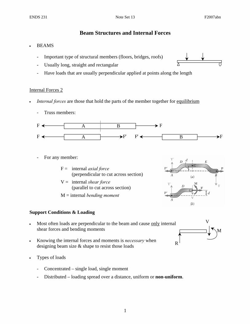
Beam Structures and Internal Forces
• BEAMS
- Important type of structural members (floors, bridges, roofs)
- Usually long, straight and rectangular
- Have loads that are usually perpendicular applied at points along the length
Internal Forces 2 • Internal forces are those that hold the parts of the member together for equilibrium
- Truss members:
- For any member:
F = internal axial force (perpendicular to cut across section) V = internal shear force (parallel to cut across section) M = internal bending moment Support Conditions & Loading • Most often loads are perpendicular to the beam and cause only internal
shear forces and bending moments • Knowing the internal forces and moments is necessary when
designing beam size & shape to resist those loads • Types of loads
- Concentrated – single load, single moment
- Distributed – loading spread over a distance, uniform or non-uniform.
T´
V
T´
T
ENDS 231 Note Set 13 F2007abn
2
V
M
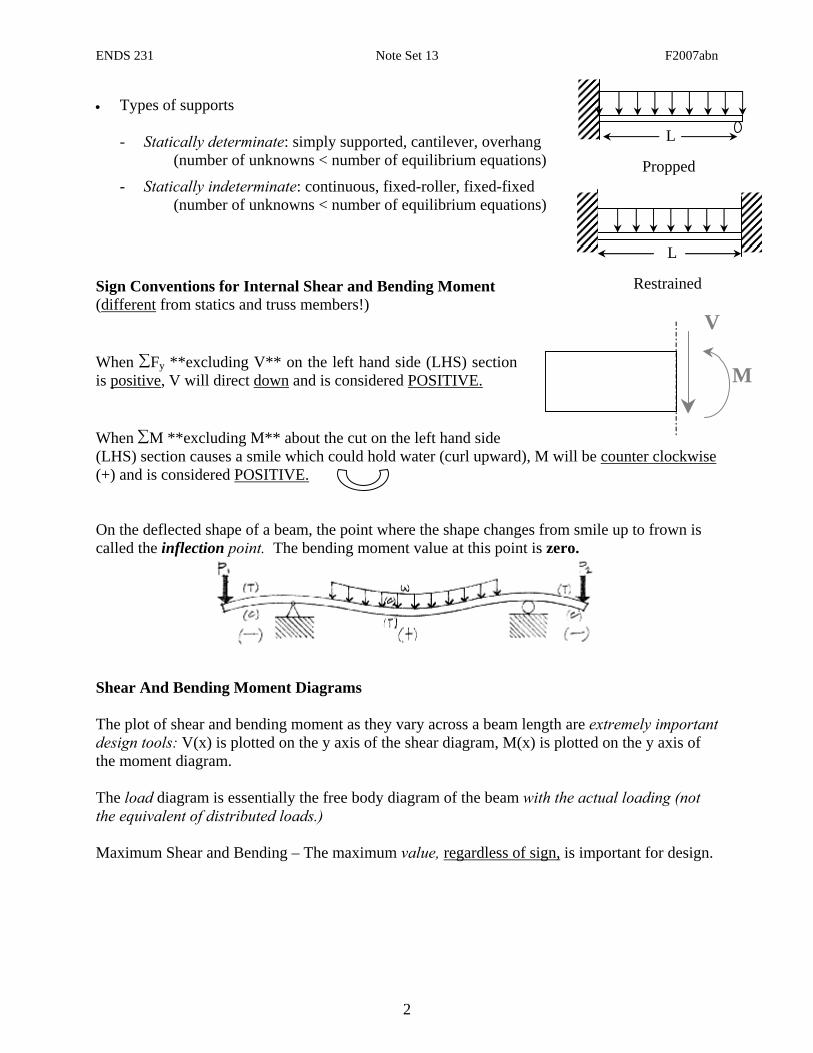
• Types of supports
- Statically determinate: simply supported, cantilever, overhang (number of unknowns < number of equilibrium equations)
- Statically indeterminate: continuous, fixed-roller, fixed-fixed (number of unknowns < number of equilibrium equations)
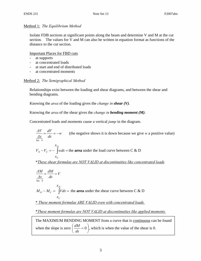
Sign Conventions for Internal Shear and Bending Moment (different from statics and truss members!) When ∑Fy **excluding V** on the left hand side (LHS) section is positive, V will direct down and is considered POSITIVE. When ∑M **excluding M** about the cut on the left hand side (LHS) section causes a smile which could hold water (curl upward), M will be counter clockwise (+) and is considered POSITIVE. On the deflected shape of a beam, the point where the shape changes from smile up to frown is called the inflection point. The bending moment value at this point is zero.
Shear And Bending Moment Diagrams The plot of shear and bending moment as they vary across a beam length are extremely important design tools: V(x) is plotted on the y axis of the shear diagram, M(x) is plotted on the y axis of the moment diagram. The load diagram is essentially the free body diagram of the beam with the actual loading (not the equivalent of distributed loads.) Maximum Shear and Bending – The maximum value, regardless of sign, is important for design.
L
L
Propped
Restrained
ENDS 231 Note Set 13 F2007abn
3
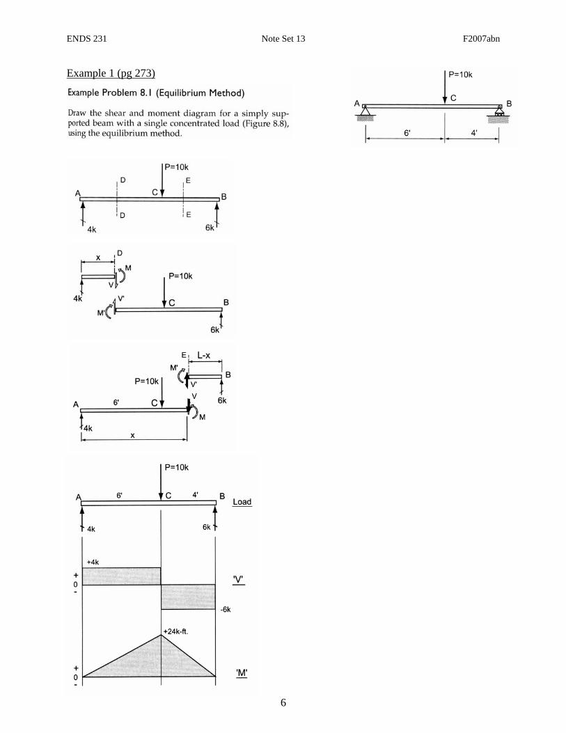
Method 1: The Equilibrium Method
Isolate FDB sections at significant points along the beam and determine V and M at the cut section. The values for V and M can also be written in equation format as functions of the distance to the cut section. Important Places for FBD cuts - at supports - at concentrated loads - at start and end of distributed loads - at concentrated moments
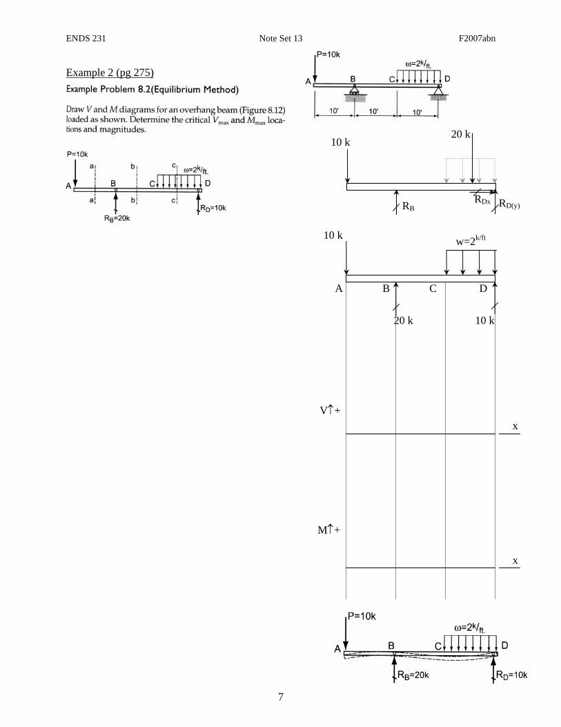
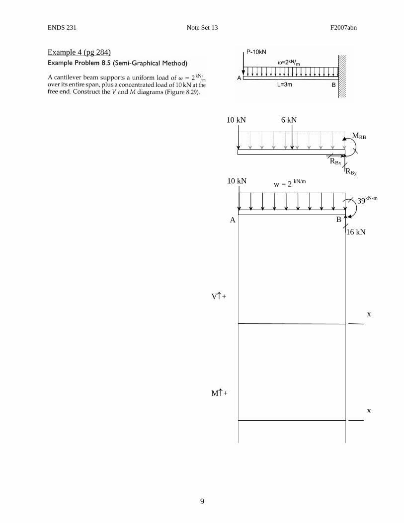
Method 2: The Semigraphical Method
Relationships exist between the loading and shear diagrams, and between the shear and bending diagrams. Knowing the area of the loading gives the change in shear (V). Knowing the area of the shear gives the change in bending moment (M). Concentrated loads and moments cause a vertical jump in the diagram.
wdxdV
ΔxΔV
−==
0lim
(the negative shows it is down because we give w a positive value)
∫ =−=−D
C
CD
x
xwdxVV the area under the load curve between C & D
*These shear formulas are NOT VALID at discontinuities like concentrated loads
Vdx
dMΔxΔM
==
0lim
∫ ==−D
C
CD
x
xVdxMM the area under the shear curve between C & D
* These moment formulas ARE VALID even with concentrated loads. *These moment formulas are NOT VALID at discontinuities like applied moments. The MAXIMUM BENDING MOMENT from a curve that is continuous can be found
when the slope is zero ⎟⎠⎞
⎜⎝⎛ = 0
dxdM , which is when the value of the shear is 0.
ENDS 231 Note Set 13 F2007abn
4
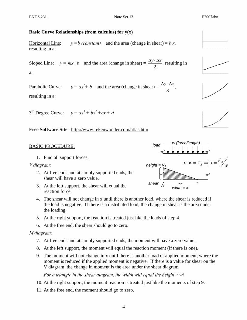
Basic Curve Relationships (from calculus) for y(x) Horizontal Line: y =b (constant) and the area (change in shear) = b·x, resulting in a:
Sloped Line: y = mx+b and the area (change in shear) = 2
xy Δ⋅Δ , resulting in
a:
Parabolic Curve: y = ax2+ b and the area (change in shear) = 3
xy Δ⋅Δ ,
resulting in a: 3rd Degree Curve: y = ax3 + bx2 +cx + d Free Software Site: http://www.rekenwonder.com/atlas.htm BASIC PROCEDURE:
1. Find all support forces. V diagram:
2. At free ends and at simply supported ends, the shear will have a zero value.
3. At the left support, the shear will equal the reaction force.
4. The shear will not change in x until there is another load, where the shear is reduced if the load is negative. If there is a distributed load, the change in shear is the area under the loading.
5. At the right support, the reaction is treated just like the loads of step 4. 6. At the free end, the shear should go to zero.
M diagram: 7. At free ends and at simply supported ends, the moment will have a zero value. 8. At the left support, the moment will equal the reaction moment (if there is one). 9. The moment will not change in x until there is another load or applied moment, where the
moment is reduced if the applied moment is negative. If there is a value for shear on the V diagram, the change in moment is the area under the shear diagram.
For a triangle in the shear diagram, the width will equal the height ÷ w! 10. At the right support, the moment reaction is treated just like the moments of step 9. 11. At the free end, the moment should go to zero.
shear
load
height = VA
w (force/length)
width = x A
wVxVwx A
A =⇒=⋅
ENDS 231 Note Set 13 F2007abn
5
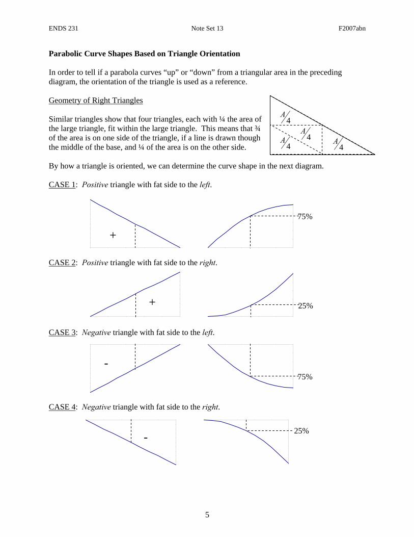
Parabolic Curve Shapes Based on Triangle Orientation In order to tell if a parabola curves “up” or “down” from a triangular area in the preceding diagram, the orientation of the triangle is used as a reference. Geometry of Right Triangles Similar triangles show that four triangles, each with ¼ the area of the large triangle, fit within the large triangle. This means that ¾ of the area is on one side of the triangle, if a line is drawn though the middle of the base, and ¼ of the area is on the other side. By how a triangle is oriented, we can determine the curve shape in the next diagram. CASE 1: Positive triangle with fat side to the left.
CASE 2: Positive triangle with fat side to the right.
CASE 3: Negative triangle with fat side to the left.
CASE 4: Negative triangle with fat side to the right.
4A
4A
4A
4A
25% -
75% -
25% +
75%
+
ENDS 231 Note Set 13 F2007abn
6
Example 1 (pg 273)
ENDS 231 Note Set 13 F2007abn
7
Example 2 (pg 275)
20 k 10 k
RDxRB RD(y)
10 k w=2k/ft
20 k 10 k
x V↑+
x
M↑+
A B C D
ENDS 231 Note Set 13 F2007abn
8
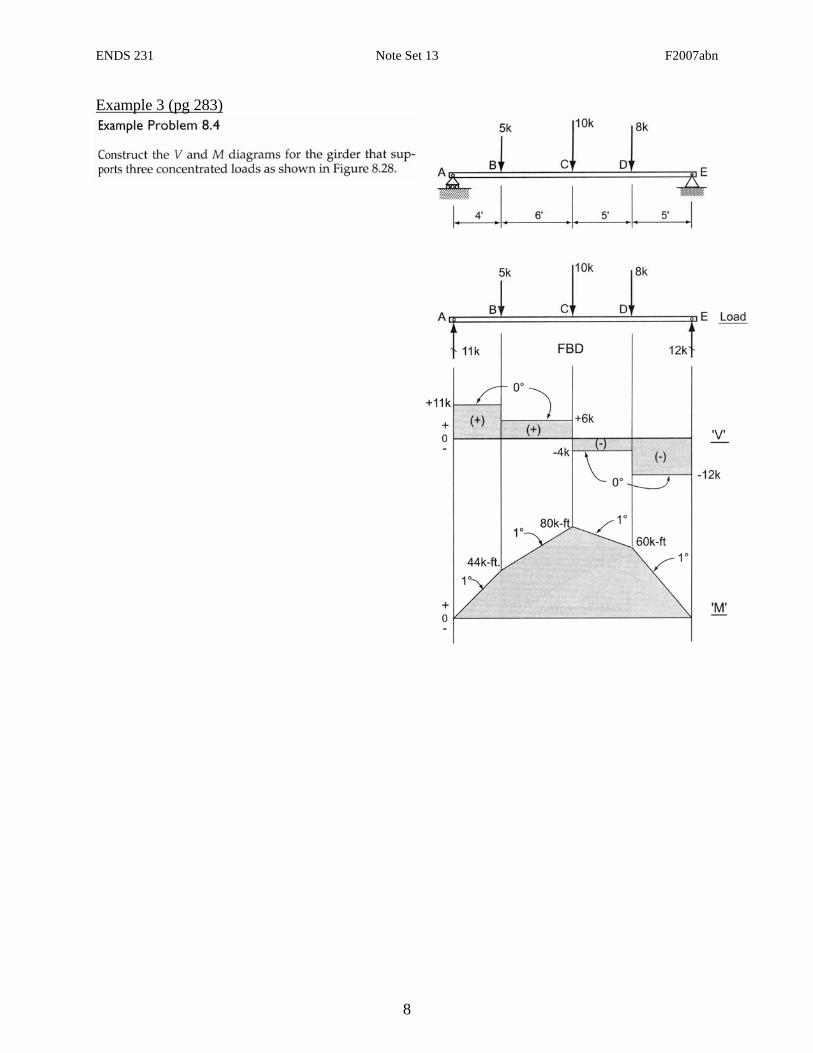
Example 3 (pg 283)
ENDS 231 Note Set 13 F2007abn
9
Example 4 (pg 284)
6 kN 10 kN
RBx
RBy
MRB
x
V↑+
x
M↑+
10 kN
16 kN
39kN-m
w = 2 kN/m
A B
ENDS 231 Note Set 13 F2007abn
10
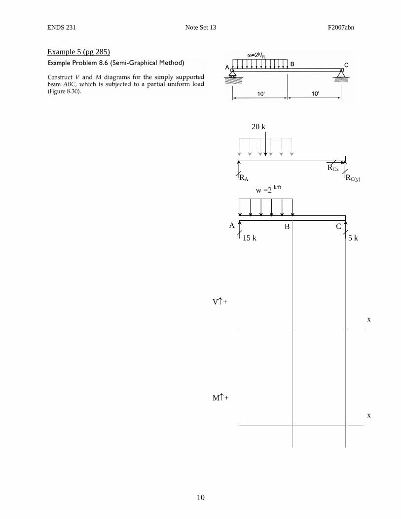
Example 5 (pg 285)
20 k
RCx
RC(y)
x
V↑+
x
M↑+
5 k
RA
15 k
w =2 k/ft
A B C
ENDS 231 Note Set 13 F2007abn
11
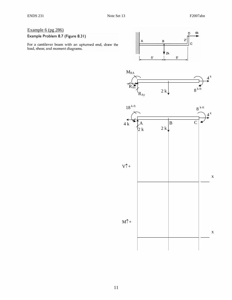
Example 6 (pg 286)
2 k
RAx
RAy 8 k-ft
x
V↑+
x
M↑+
8 k-ft
A
MRA
2 k
2 k
18 k-ft
B C4 k
4 k
4 k

ENDS 231 Note Set 13 F2007abn
12
Example 7 (pg 287)
450 N
RBx
RB(y)
x
V↑+
x
M↑+
450 N
A B
RA(y)
450 N
C
450 N
w = 300N/m