Embed Size (px)
Citation preview
Beam Shear Design with Welded Wire Fabric:
ACI318 vs. AASHTO LRFD
by Brian A. Green
A Thesis Submitted to the Graduate
Faculty of Rensselaer Polytechnic Institute
in Partial Fulfillment of the
Requirements for the Degree of
MASTER OF SCIENCE
Approved:
Larry J. Peeser Thesis Advisor
Äpsgovsd tor piiciic r&Leoaei '
[»TIC QUALITY INSPECTED S
Rensselaer Polytechnic Institute Troy, New York
April 1996 (for Graduation May 1996)
19960607 167

CONTENTS
Page
LIST OF TABLES iv
LIST OF FIGURES v
ABSTRACT ^
1. INTRODUCTION AND HISTORY 1
a. ACI318-95 Design Method 1
b. AASHTO LRFD Design Method 3
c. Welded Wire Fabric (WWF) 4
2. THEORY 7
a. ACI 318-95 8
b. AASHTO LRFD 9
c. Significant Equations-ACI 318-95 12
d. Significant Equations-AASHTO LRFD 13
3. RESULTS 15
a. ACI 318-95 vs. AASHTO LRFD 15
b. Welded Wire Fabric (WWF) 20
4. DISCUSSION AND CONCLUSIONS 25
a. ACI 318-95 vs. AASHTO LRFD 25
b. Welded Wire Fabric (WWF) 26
LITERATURE CrTED 28

Page
LITERATURE REFERENCED 31
APPENDIX 1 (Design Examples IA and IB) 35
a. Example IA: Prestressed Concrete Bulb Tee 35
(1) Method A: ACI318-95 37
(2) Method B: AASHTO LRFD 38
b. Example IB: Prestressed Concrete Type IV Girder 40
(1) Method A: ACI 318-95 41
(2) Method B: AASHTO LRFD 41
APPENDDC 2 (Computer program RESPONSE analysis) 43
a. Example IA: Computer analysis 43
b. Example IB: Computer analysis 49

LIST OF TABLES
Page
Table 1. Allowable Yield Strengths 5
Table 2. Experimental Verification of 528 Tests 18
Table 3. Strength Predictions Using ACI318-95 and the General Method 24
Table 4. Critical Locations and Loads- Example IA 36
IV

LIST OF FIGURES
Page
Figure 1. Number of Papers on Shear Design Published in ACI Journal 2
Figure 2. Number of Equations for Shear Design in ACI Code 3
Figure 3. Types of Cracking in Concrete Beams 7
Figure 4. Reinforced Concrete Panels Subjected to Shear 9
Figure 5. ACI 318-95 Shear Design Equations 12
Figure 6. AASHTO LRFD (General Method) Shear Design Equations 13
Figure 7. Values of 6 and ß for Members with Web Reinforcement 14
Figure 8. Values of 8 and ß in Members without Web Reinforcement 14
Figure 9. Influence of Member Size and Maximum Aggregate Size on Shear 16
Figure 10. Experimental and Predicted Failure Shears for 528 Tests 19
Figure 11. Anchorage of WWF in Concrete Beams 21
Figure 12. Reinforcement Details: Beams with WWF Shear Reinforcement 22
Figure 13. Crack Patterns of Four Beams 23
Figure 14. Girder Cross Section Example IA 35
Figure 15. Prestressing Steel Harping Pattern Example IA 36
Figure 16. Girder Cross Section Example IB 40
Figure 17. Transformed Cross Section Example IB 40

ABSTRACT
Since 1963, the shear design of reinforced and prestressed concrete beams has
become unnecessarily complicated. There are currently two different procedures used to
design and detail the steel shear reinforcement in concrete beams. The first method, used
by the American Concrete Institute (ACI), is purely empirical. Their current design guide,
the Building Code Requirements for Structural Concrete (ACI 318-95) and Commentary
(ACI 318R-95)1 uses the results of beam tests to produce the current code shear
reinforcement requirements. The second method, recently adopted by the American
Association of State Highway and Transportation Officials (AASHTO) in their Load and
Resistant Factor Design (LRFD) code2 is called the Modified Compression Field Theory
(MCFT) approach. The MCFT approach, also referred to as the General method, was
developed by Professor Michael P. Collins at the University of Toronto. The MCFT
approach models the beam's steel reinforcement as a variable angle truss. According to
Collins, the resulting steel shear reinforcement is designed based on a "physically
significant" quantity.3 The method relates the average strain in the longitudinal steel
reinforcement with the principal strains in the beam. The AASHTO method greatly
simplifies the design approach, since the same equations apply to both prestressed and
non-prestressed concrete beams and to any beam geometry.
According to two separate studies conducted by Collins and Mitchell,3,4 the MCFT
approach produces more accurate answers than the empirical ACI method. Collins
VI

concludes that the "General method" is more accurate than the ACI method, especially
when used to determine the shear reinforcing required in "large, lightly reinforced
members and members subjected to high axial compression where the ACI equations can
be seriously unconservative" (Collins, 1996). He further states that the ACI approach is
overly conservative for "uniformly loaded members, members with inclined prestressing
tendons and members subjected to high axial tension" (Collins, 1996). In his study,
Mitchell predicted the shear capacity of four beams based on both the ACI and MCFT
approaches. His predictions were then verified by experimental testing. In his
conclusions, he states that "the predictions of shear capacity using the modified
compression field theory are more accurate than the predictions using ACI 318M-895
expressions" (Mitchell, 1994).
The ACI and AASHTO shear design methods seem to be diverging in approach.
While both methods provide safe designs, they present a different methodology towards
shear reinforcement design. As Robert W. Cannon states in Concrete International, the
changes in shear design are "due to academic research and not based on past performance
of structures, or (their) impact on construction procedures."6 The MCFT approach
adopted by AASHTO is not a result of the failure of the ACI code in design practice.
Rather, it is an attempt to provide a rational approach to shear design.
A recent development in thin-webbed precast concrete beams is the use of Welded
Wire Fabric (WWF) as shear reinforcement. The use of WWF has been shown to greatly
reduce the time, cost and the difficulty of on-site construction.7
vu

INTRODUCTION AND HISTORICAL REVIEW
Over the last several years, two methods have primarily been used to design the
shear reinforcement in prestressed and non-prestressed concrete beams. The focus of my
research was prestressed concrete beams using Welded Wire Fabric (WWF) as shear
reinforcement. Specifically, I wanted to compare the shear design approach used by ACI
318 with that used by the AASHTO LRFD design specifications for WWF.
The history of shear design methods can be traced back to about the year 1890 as
is shown in Figure 1. About the turn of this century, Morsch8 investigated the diagonal
cracking in concrete railroad beams and developed the 45 degree truss analogy still used
as the basis for the ACI code provisions today.
ACI 318 Method
In 1955, a failure of an air force warehouse910 led to the first major changes in the
ACI shear provisions. During the 1960's, ACI-ASCE Committee 326 refined the ACI
shear provisions based on the results of tests conducted on over 924 beams. Similarly,
during the 1970's, ACI-ASCE Committee 426 further refined the shear provisions based
on beam tests. As shown in Figure 1, research in the shear behavior of concrete beams
has increased dramatically in recent years.

NUMBER OF PAPERS ON SHEAR DESIGN PUBLISHED IN ACI JOURNAL
50 -I
45 -
40
35
30
25
20 -
15 -
10
5
0
Morsch's Book
Air Force Warehouse Failure
YEAR
'I
oooooooooo OOi-CMCD^tirjCDh-CD 0005050505050)050)0)
_l_
o o O) o O) o
Figure 1. Number of papers on shear design (Collins, 1996)
The history of the ACI empirical approach to shear design has a well-documented
history. The ACI 318 specifications have become increasingly complex over the years.
As shown in Figure 2, the number of equations required for beam shear design has risen
significantly. Up until approximately 1963, the ACI 318 specifications included only 4
equations for shear design and analysis. The ACI 318-95 specification currently includes
over 40 equations for shear design and analysis. Even though these equations do not all

need to used or checked for each design, the number of complex equations in the ACI
code makes it extremely difficult to use without adequate training and experience.
45
40
35
30
25
20
15
10
5
0
NUMBER OF EQUATIONS FOR SHEAR DESIGN IN ACI CODE
o o CD
n o CVJ CD
O CO CD
o CD
o IT) CD
YEAR
o o CO CD
i
o o CD O CD o i- CNJ
Figure 2. Number of equations for Shear Design in ACI Code (Collins, 1996)
AASHTO LRFD Method
The recently adopted 1994 AASHTO LRFD design guide uses the Modified
Compression Field Theory (MCFT) approach developed by Professor M.P. Collins at the
University of Toronto. The approach is "based on equilibrium, compatibility and the
stress-strain characteristics of cracked reinforced concrete" (Collins, 1996). In fact,

Collins developed the MCFT approach based on the desire of the 1973 ACI-ASCE Shear
Committee11 that the "design regulations for shear strength can be integrated, simplified,
and given a physical significance." Testing done since 1971 has shown that, "in general,
the angle of inclination of the concrete compression is not 45 degrees, and that equations
based on a variable angle truss provide a more realistic basis for shear design" (Collins,
1996). The MCFT method provides a rational and simplified approach to shear design.
As a result, it has been adopted by several design codes in Canada and in the AASHTO
LRFD specifications in the United States.
In his text, Reinforced Concrete: Mechanics and Desien ,12 James G. MacGregor
disagrees with the MCFT approach used by Collins. He states that one cannot predict
flexure-shear cracks based on the principal tensile stresses in a section, unless web shear
cracks precede them (which sometimes occurs in prestressed concrete beams but rarely
occurs in reinforced concrete beams). MacGregor, a member of the ACI 318 committee,
believes an empirical approach (such as ACI 318-95) is the only way to predict beam
cracking. He and several other "subject matter experts" advocate the use of arching
action in "disturbed" regions of a beam (such as near a support) to explain shear failure.
Welded Wire Fabric
Recently, the use of Welded Wire Fabric (WWF), primarily in prestressed concrete
construction, has taken on added importance. For instance, in Germany, WWF constitutes
over 40% of the steel reinforcement market and has been used successfully for over 50

years (Mitchell, 1994). The use of prefabricated WWF cages instead of conventional L-
shaped or U-shaped stirrups for shear reinforcement has led to time savings of 70-75%
during actual construction (Mitchell, 1994). In addition, it has greatly reduced the amount
of steel reinforcement required in a given concrete beam, thereby greatly reducing the
cost. However, here in North America, the use of WWF for shear reinforcement is just
beginning to be an accepted practice. For instance, in 1980, the Precast Concrete Institute
(PCI) and the Wire Reinforcing Institute (WRI) formed an ad hoc joint PCI/WRI
committee to study the use of WWF for shear reinforcement.13 This has led to ACI
acceptance of WWF for use as shear reinforcement. ACI has currently restricted the
allowable yield strengths in the wire material (see Table 1 below).
ACI Code Version Allowable Yield Strength. Fv (ksi)
ACI 318-77 60 ksi
ACI 318-89 (Revised 1992) 60 ksi
ACI 318-95 60+ ksi (up to stress corresponding to 0.35 percent strain)
Table 1. Allowable Yield Strength for Wire Reinforcement Based on ACI 318-XX.
One of the main advantages of using WWF is that it may be fabricated with
whatever size wires or spacings that the designer deems necessary. Instead of the
standard WWF typically used for concrete slabs, the designer can now specify exactly

what types of steel reinforcement he wishes to use. If crack control is a concern, he can
reduce the wire spacing. If strength is a primary concern, the designer can use stronger
deformed wire or increase the wire size in the fabric.
Most of the recent testing of wire reinforcing has focused on the wire properties:
ductility, yield strength and bonding characteristics (smooth and deformed wire). Other
parameters investigated were the requirements for proper anchorage, the quality and
strength of welds at wire intersections and the need for proper wire sizes and spacings
when WWF is used for shear reinforcement (Mitchell, 1994). In fact, Mansur, Lee and
Lee14,15 concluded that the use of WWF as shear reinforcement results in smaller measured
maximum crack widths than those cracks resulting from the use of regular mild steel
stirrups. They found that these smaller cracks were a direct result of the smaller steel
spacings and the more effective "staple action" across the potential crack. They also
concluded that deformed WWF performed better than the smooth WWF in terms of
anchorage and overall crack control. This was verified by tests done by Pincheira,
Rizkalla, and Attiogbe.16 Mitchell confirmed that deformed WWF did lead to smaller
cracks at service loads than those beams reinforced with conventional stirrups. He also
stated that there was sufficient anchorage of the WWF when two horizontal wires were
used and that WWF exhibited sufficient ductility for use as shear reinforcement. Mitchell
also concluded that the "nominal yield stress of 500 Mpa (about 72.5 ksi) could be used
in design calculations" (Mitchell, 1994). This eventually led to ACI Committe 318
adoption of the ultimate yield stress of 60+ ksi (that is, up to the stress corresponding to a
0.35 percent strain) in ACI 318-95.

THEORY
Different types of cracking behavior are shown in Figure 3 below. Overall, there
are two critical types of inclined cracking in concrete beams. Flexure-shear cracks start as
vertical flexure cracks. The flexure-shear crack then develops "when the combined shear
and tensile stress exceeds the tensile strength of the concrete" (ACI 318-95). Web-shear
cracking "begins from an interior point in a member when the principal tensile stresses
exceed the tensile strength of the concrete" (ACI 318-95).
APPLIED LOAD
f^wF77 CONTINUOUS SUPPORT
< »
FLEXURALAND FLEXURE-SHEAR
WEB- SHEAR
FLEXURAL AND FLEXURE- SHEAR
IT SIMPLE SUPPORT
< *«
WEB- SHEAR
Figure 3. Types of Cracking in Concrete Beams (Adapted from ACI 318-95)
Over the years, more research was done to look specifically at the failure
mechanisms along the diagonal cracks. Phenomenon such as "aggregate interlock" at the

crack interface and "dowel action" of the reinforcing steel with the concrete became more
important for continued research.
ACI318-95 Method
ACI Committee 318 established empirical shear reinforcement equations based on
the results of numerous beam tests. The model for the equations is based on a 45 degree
truss analogy. The ACI 318-95 expression for the shear strength of non-prestressed
concrete beams is:
Vn=Vc + Vs=2jJ;bwd + ^- where s
Vn = nominal total shear capacity of the section
Vc = nominal shear capacity of the concrete
Vs = nominal shear capacity of the steel reinforcement
//= concrete compressive strength
bw = effective web width of section
d = effective depth of section from extreme compression fiber to centroid of
longitudinal steel reinforcement
Av = cross sectional area of steel shear reinforcement
/ = yield strength of steel reinforcement
s = spacing of shear reinforcement
For prestressed concrete beams, the ACI equations are slightly more complex and
will not be given here (see ACI 318-95).

AASHTO LRFD Method
The MCFT approach is based on the strain compatibility in the cracked concrete
beam and allows for the fact that "even after cracking, tensile stresses in the concrete
between the cracks can resist shear stresses." (Collins, 1996). In fact, Collins rationalizes
that the "loss of tensile stresses in the concrete at the crack must be replaced by increased
steel stresses" which are ultimately taken up by the longitudinal steel. This fact is shown
in Figure 4 below:
1 ■ A f
(b) Calculated average stresses (c) Local stresses at crack
Figure 4. Reinforced concrete panels subjected to shear (Collins, 1996)
According to the MCFT, the nominal shear strength of a section is given by:
vn = vc + vd + vp

10
where V = shear load taken by a component of the prestressing steel p
A fd cot0 But, V = v where 0 = angle of principle compression
and Vc = ßVZ'Mv where ß = tensile stress factor
However, ß and 0 are functions of the average longitudinal strain, ex, the shear stress,
v, and the crack spacing, sx, at the section such that:
ttla 4cote , 216 where P 1 + V5ÖÖ17 03+ 24Wcr
a+ 0.63
a! = reinforcement bonding characteristics (1.0 for deformed bars)
a 2 = load factor (1.0 for short term monotonic loading)
8! = principle tensile strain
wcr= crack width
a = maximum aggregate size
but we also must calculate the shear stress at the critical section using the expression
V -V ' n p v = - bd "v V
and the average strain in the longitudinal steel reinforcement given by
M -!L + 0.5(Nu + VucotQ)-Apsfpo
e =A ESAS + EpAp
where

11
Mu = ultimate bending moment load on the section
Nu = ultimate axial load on section
Vu = ultimate shear load on section
A = effective cross sectional area of prestressing steel ps
f 0 = stress in prestressed tendon when surrounding concrete is at zero stress
Es = elastic modulus of longitudinal reinforcement
As = effective cross sectional area of longitudinal steel reinforcement
Ep = elastic modulus of prestressing steel
A = effective cross sectional area of prestressing steel
The significant equations from both methods are summarized in Figures 5 and 6 below:
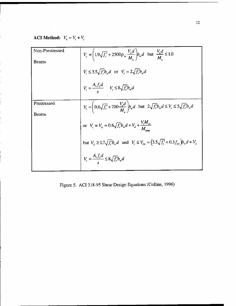
ACI Method: Vn = Vc + Vs
12
Non-Prestressed
Beams vc = l.94f] + 2500p w^-
V Mu) hd but ^<1.0
VeZ*5jTXd or Vc=2jf~Xd
s
Prestressed
Beams vc =
f r~, Vd) 0.6A/^ + 700-^-
V lV1u )
bj but 2jf;bwd<vc<5jTxd
r— VM or Vc = Vci=0.6jf;bwd + Vd+-^
max
but Vci > LlJTXd and Vc < Vm = (3.5^+03fpc )bwd + Vp
vs=^-<%4i:bj s
Figure 5. ACI 318-95 Shear Design Equations (Collins, 1996)

13
General Method (AASHTO LRFD/MCFT): Vn = Vc + Vs + V
ve = ßVIVv ^ = ^ dv cote s
where ß and 0 are functions of the strain, £^,
shear stress, v , and crack spacing, *x
Vn-V where v = — -
bd V V
d and ex=—v-
+ 0.5{NU + Vucote)- ■A f psJ po
Note: All equations use U.S. units.
Figure 6. General Method Shear Design Equations (Collins, 1996)
To ease the design process and to insure that concrete crushing does not occur,
Professor Collins developed two tables to use with the General method. These tables give
values for 9 and ß based on the average strain in the longitudinal reinforcing steel,
ex, and the shear stress, v, at the critical section of the beam. The critical section for
beams is located at a distance dv cot 6 from the middle of the support. The tables are
given for beams with and without steel reinforcement respectively. The table values shown
are for U.S. units.

14
V Longitudinal strain e_, x 1000
s: <0 <0.25 <0.50 2 1.00 5 1.50 5 2.00
< 0.050 6deg 27.0 28.5 29.0 36.0 41.0 43.0
ß 4.88 3.49 2.51 2.23 1.95 1.72
< 0.075 edcg 27.0 27.5 30.0 36.0 40.0 42.0
ß 4.88 3.01 2.47 2.16 1.90 1.65
< 0.100 Gdeg 23.5 26.5 30.5 36.0 38.0 39.0
ß 3.26 2.54 2.41 2.09 1.72 1.45
< 0.150 Gdeg 25.0 29.0 32.0 36.0 36.5 37.0
ß 2.55 2.45 2.28 1.93 1.50 1.24
< 0.200 Gdeg 27.5 31.0 • 33.0 34.5 35.0 36.0
ß 2.45 2.33 2.10 1.58 1.21 1.00
5 0.250 edcg 30.0 32.0 33.0 35.5 38.5 41.5
ß 2.30 2.01 1.64 1.40 1.30 1.25
Figure 7. Values of 0 and ß for members with web reinforcement (U.S. units).
(Collins, 1996)
Longitudinal strain tx x 1000
*I
£0 £0.25 £0.50 £1.00 £1.50 £2.00
£5 in. 6deg 27.0 29.0 31.0 34.0 36.0 deg 38.0 deg
ß 4.94 3.78 3.19 2.56 2.19 1.93
£ 10 in. 9 deg 30.0 34.0 37.0 40.0 43.0 45.0 deg
P 4.65 3.45 2.83 2.19 1.87 1.65
£ IS in. 9 deg 32.0 37.0 40.0 45.0 48.0 50.0 deg
P 4.47 3.21 2.59 1.98 1.65 1.45
£25 in. Odeg 35.0 41.0 45.0 51.0 54.0 57.0 deg
P 4.19 2.85 2.26 1.69 1.40 1.18
£ 50 in. 9deg 38.0 48.0 53.0 59.0 63.0 66.0 deg
P 3.83 2.39 1.82 1.27 1.00 0.83
£100 Odeg 42.0 55.0 62.0 69.0 72.0 75.0 deg in. P 3.47 1.88 1.35 0.87 0.65 0.52
Figure 8. Values of 9 and ß for members without web reinforcement (U.S. units).
(Collins, 1996)

RESULTS
To test the difference between using the two methods, I chose two specific
example problems to demonstrate the procedures for shear design. These design examples
are contained in Appendix 1. In addition, I used the RESPONSE17 computer program
developed by Collins to analyze the two example problems. The results of this computer
analysis are outlined in Appendix 2.
Both the ACI 318-95 and the AASHTO LRFD approach produce safe, economical
designs. The MCFT approach better approximates experimental test results. In a study
conducted by Xuan, Rizkalla and Maruyama18 in 1987, the authors concluded that "ACI
code underestimates the ultimate shear capacity for beams with shear reinforcement by 43
to 79 percent." They go on to state that this is due to the measured shallow angle, 6, of
the diagonal cracks which measured about 25 degrees instead of the 45 degrees assumed
by the ACI code.
The benefit of using the General method, according to Collins, is that "prestressed
concrete beams, non-prestressed concrete beams and partially prestressed concrete beams
having a wide variety of cross-sectional shapes can all be designed using the same basic
expressions. The beneficial effects of prestressing are accounted for in the design by
allowing lower values of theta to be used which will result in less transverse
reinforcement."19
15

16
Durrani and Robertson conclude that "the observed concrete shear strengths are
between 28 and 54 percent higher than the ACI Code predicted values" (Durrani, 1987).
Their testing also resulted in cracks at 0 = 30 degrees to the longitudinal axis of the
beams. The nominal shear failure loads that they observed were 37 to 55 percent greater
than the ACI predicted values.
Perhaps the best comparison between the ACI 318-95 and the AASHTO LRFD
shear design methods is done by Collins. Based on parameters such as member size and
maximum aggregate size, Collins compares the results of the two approaches with his own
experimental results as shown below in Figure 9.
psi o units
3.2-
2.8-
2.4-
0.5 dim)
1.0 1.5 2.0 2.5 3.0
(3 = 2.0F \\
JT 1.6-
1.2
0.8-
0.4-
UilllUIUUUUllllUUlUUU i
-dh
t-v -12rf-
calculated here
V
\
ACI 318-95 Prediction
\ t3-.„ General Method Prediction
Experimental • ~-^ ^-^^ 'o- ^
-• .
t>A 9 = -ÜT- = 0.004 bd /; = 3500 psi (24.1 MPa)
fy = 52 ksi (386 MPa)
J I I I I I I I L
MPa units
0.25
0.20
0.15
0.10
0.05
01 23456789 10 d (feet)
Figure 9. Influence of member size and maximum aggregate size on shear stresses at
failure (Collins, 1996).

17
Figure 9 shows the predicted shear failure levels based on ACI318-95, the General
Method and the experimental results. On the vertical axis, the tensile stress factor, ß, is
plotted. Increasing beam depth is plotted on the horizontal axis. In this case, the ACI
318-95 method is unconservative, since it overestimates the concrete strength of the
section. The General method, while also unconservative, gives a much better
approximation of the experimental beam behavior. Collins summarizes his results with
those done by several researchers in recent years as shown in Table 2. A total of over 528
beams were tested. Based on a number of parameters such as beam size, loading, and
concrete strength, this table shows that the ACI approach can be very inaccurate and
unconservative for large, lightly reinforced members and members under high axial
compression. For members with uniform loads, members with inclined prestressing
tendons and members under high axial tension, the ACI approach is unnecessarily
conservative (Collins, 1996).

18
Date
Number and specimen
type Loading Depth, in. Concrete,
psi
Stirrups
psi
Experiment/predicted
ACI General
Reference Mean
Coefficient of variation.
percent Mean
Coefficient of variation.
percent
Kani'9 1979 68
rectangular beams
2 point loads on simple span
6to48 2230 to 5320 0 1.23 14.9 1.35 8.0
Kani" 1979 95T-beams 2 point loads on simple span
12 2510 to 5550 0 1.60 11.5 1.63 10.1
Shioya15 1989 13
rectangular beams
Uniformly distributed load on
simple span 5 to 124 2860to4130 0 0.86 42.9 0.98 25.1
Gupta20 1993 10
rectangular beams
End loads applying shear and
compression 12 8700 to 9120 0 to 170 0.85 27.3 1.13 16.8
Adebar and Collins2'
1996 7 rectangular
columns End loads applying shear and tension
12 6700 to 8500 0 2.75 51.4 0.90 12.8
Gregor and Collins22 1993
öprestressed bridge girders
Uniformly distributed load on continuous span
36 6500 to 8400 psi 370 to 590 1.06 17.5 1.37 12.7
Collins and Vegh23 1993 14
rectangular beams
Point loads on continuous span
11 to 36 7250 to 13.500 0 to 120 0.84 18.2 1.07 15.9
Griezic, Cook, and Mitchell24 1993 4T-beams
Uniformly distributed load on
simple span 16 5800 225 to 350 1.34 12.2 1.34 12.6
Haddadin. Hong, and Mattock23 1971 59T-beams
Point loads on beams with tension or compression
18.5 1950 to 6500 0 to 700 1.61 32.3 1.45 18.7
Elzanaty, Nilson, and Slate26 1986
33 prestressed
I-beams
2 point loads on simple span
14 and 18 6000 to 11.400 0to700 1.07 11.6 1.35 9.5
Pasley. Gogoi. Darwin, and
McCabe27 1990 13T-beams
Point loads on continuous span
18 4500 0to82 0.99 12.0 1.27 7.0
Mattock2" 1969 31
rectangular beams
Point loads on beams with tension or compression
12 2200 to 8000 0 1.56 24.7 1.45 14.0
Bennett and Balasooriya29 1971
20 prestressed
I-beams
2 point loads on simple span
10 and 18 4400 to 6460 630 to 1900 1.71 19.4 1.46 18.2
Bennett and Debaikey2»
1974 22
prestressed I-beams
Point load on simple span
13 6000 to 10.500 103 to 5600 1.15 9.9 1.54 10.9
Moody, Viest, Elstner. and Hognestad3'
1954 12
rectangular beams
Point load on simple span
12 880 to 4600 0 1.27 14.2 1.27 13.5
MacGregcc32 1960 33
prestressed I-beams
Point load on simple span
12 2400 to 7000 0 to 470 1.09 25.8 1.54 22.5
Oleson. Sozen. and Siess33 1967
27 prestressed
I-beams
Point load on simple span
12 2450 to 6700 0u>350 1.06 18.8 1.59 15.3
Roller and Russell34 1990 10
rectangular beams
Point load on simple span
25 to 34 10,500 to 18,170 0 to 1176 1.05 20.0 1.19 13.5
Shahiwy, Robinson, and Batchelor53 1993
39 full-size prestressed
bridge girders
Point load on simple spaa
44 6000 165 to 1670 1.09 19.5 1.13 15.8
Yoon. Cook, and Mitchell36 1996
12 rectangular
beams
Point load on simple span
30 5220 to 12,615 0 to 145 1.14 13.8 1.07 10.3
528 beams | Average 1.32 33.7 1J9 19.7
Table 2. Experimental verification of ACI 318 vs. General Method (Collins, 1996)

19
Based on the results of Table 2 and Figure 10 below, it can easily be seen that the
General method better represents the actual physical behavior of the beam under loading
(Collins, 1996).
800
0 100 200 300 400 500 600 700 800 vcalc iki?s>
,/j Mean = 1.32 COV = 30.1%
0 20 40 60 80 100
%e <kiPs>
(a) ACI
I
700-
600
_ 500 </) a * 400-
a
'"" 300
200
100
0
vcalc /
/'./>'
A<V
/ /
&L x
0 100 200 300 400 500 . 600 700 800 vca-c (kiPs'
100
80
s- 60
S- 40
20
0
/ '/*• ■•-■'• . /,. r
•y--.y > • fly-/
my/ -1 W*/ y V
Mean = 1.44 COV = 18.2%
0 20 40 60 80 100 vcalc (kiPs)
(b) General
Figure 10. Experimental and predicted failure shears for 528 tests: ACI vs. General
method (Collins, 1996).

20
Welded Wire Fabric
While the tensile strength of WWF turns out to be higher than that of
conventional stirrups, Xuan notes that the ductility of the WWF is significantly less than
that of the stirrups. He states that "the ultimate strain of the WWF is usually less than 2
percent while that of conventional stirrups is greater than 15 percent." (Xuan, 1988).
However, he also states that WWF "used as shear reinforcement should exhibit adequate
ductility to insure the overall ductility of the member." Xuan also concludes that
anchorage by using two horizontal wires (as outlined in both the ACI 318 and AASHTO
LRFD codes) at the top and the bottom of the vertical wires is sufficient to prevent
premature beam failure (Xuan, 1988).
In testing completed by Pincheira, Rizkalla and Attiogbe20 in 1988, the authors
state that the "deformed WWF seems to provide a slightly better crack width control
compared to conventional double-legged and single-legged stirrups." They also conclude
that anchorage of the WWF by two horizontal wires at the top and bottom of the shear
reinforcement was sufficient. However, they found that deformed "WWF is not as
effective as conventional stirrups under cyclic loading" (Pincheira, 1989).
Durrani and Robertson indicate that the "observed shear strength contribution of
the mesh reinforcement (WWF) was consistently higher than the ACI Code value by more
than 50 percent (Durrani, 1987). They also conclude that two anchorage wires are
sufficient for guarding against shear failure. Based on their testing, they conclude that
both horizontal wires are "active" in taking the load and that premature failure of one wire

21
did not lead to beam failure. However, in beams with only one horizontal wire for
anchorage, there was premature failure. The authors directly relate the strength of the
anchorage to the strength and quality of the welds in the fabric. They further state that
deformed WWF forms a better bond with the concrete than that formed by smooth WWF
(Durrani, 1987). Some details of WWF anchorage based on ACI318-95 are shown in
Figure 11:
ai d/4 maximum
■minimum of 2'
8 Wir« diameter tend (minimum)
d/4 maximum
smooth or deformed vertical wire» as required:
mid -depth of member l'd/2)
prvnory reinforcement
-2 horizontal wires top a bottom.
2 "mm.
at least the greater of d/4 or T
at least the greater of d/4 or 2"
2" min.
uter wire not above lowest prvnory reinforcement
Figure 11. Anchorage of WWF in Concrete Beams (ACI 318-95)

22
Mitchell, Griezic and Cook compared the shear strength ofWWF using both the
ACI and General method approaches (Mitchell, 1994). In their study, they tested 4 beams
using either WWF or conventional stirrups as shear reinforcement. They also kept the
same steel ratio so that they could make a direct comparison of the results between the
beams. The reinforcement details of two of the beams with deformed WWF shear
reinforcement are shown in Figure 12:
8SOO - Uedwat« StiMr ho»
Tzza •7.J—) I— im\n- ~L • JJ7.J-4
— 4tM •
tSOO - High Shaor a*om
' 4700 ~ " 1
■ I
1 USAJ ECfcfl
IM H I— ««us - "L -saoo-
2-fto. 10 tomj. 2-H». 10 ' •250mm *MC*"g"
0mm tfm* ttl^mp
tUi
•100—1 i-;
U.-U — 200 4
tMom covw 40 mm t|^, •tob cw«r 20 mm *•»
Figure 12. Detail of WWF Reinforcement in Beams A500 and B500 (Mitchell, 1994)

The cracking patterns of the four beams are shown in Figure 13:
23
A500
A400
p&rm B500
B400 "T^
Tim- 7mm, Figure 13. Cracking patterns of the four test beams (Mitchell, 1994).
The results of the comparison between the ACI empirical method and the General
method are outlined below in Table 3:

24
Test results ACI318M-89 predictions MCFT predictions
Beam Vmax at d,
kN Failure mode
V„atrf, kN
Failure mode
Vmax
VACI
Vn at d, kN
Failure mode
Vmax
VMCFT
A500 332 Flexure 200 Shear 1.66 330 Flexure 1.01
A400 334 Flexure 212 Shear 1.58 316 Flexure 1.06
B500 291 Flexure 162 Shear 1.80 267 Flexure 1.09
B400 272 Flexure 169 Shear 1.61 266 Flexure 1.02
Table 3. Strength predictions using ACI 318 and General method (Mitchell, 1994)
As a result, Mitchell concludes that the smaller diameter WWF prevents larger
cracks as compared to conventional stirrups with equivalent amounts of steel. This is a
result of the smaller wires effectively "stapling" any diagonal cracks before they can open
up. He also concludes that two horizontal wires are sufficient for anchorage. Mitchell
states that "cold-rolled deformed welded wire fabric stirrups exhibited large strains and
sufficient ductility to redistribute the stresses in the stirrups to avoid a sudden, brittle shear
failure." He goes on to state that the "predictions of shear capacity using the modified
compression field theory are more accurate that the predictions using ACI 318
expressions." In addition, he recommends using the full nominal yield stress of
500Mpa(about 72 ksi) for design calculations (Mitchell, 1994).
DISCUSSION AND CONCLUSIONS
Both the ACI 318-95 approach and the AASHTO LRFD (General method)
approach to shear design produce safe beam designs. The empirical ACI 318
specifications are the result of years of testing and code refinement. While much can be
said about the improvements in ACI shear design methods in the last 40 years, the code
has been slow to change. One of the main reasons for this is that changes in the ACI 318
code specification must be approved by a voting committee. Another reason that the ACI
318 code is slow to change is that the current specifications have "passed the test of time."
That is, they have been used successfully for many years. Despite the desire of the 1973
ACI 318 committee to have a "physically significant and rational method for shear
design," the code has remained strictly empirical in its approach to shear design.
The General method adopted by the AASHTO LRFD specifications provides a
"simplified, physically significant and rational" approach to beam shear design. This
method offers several advantages:
- it is a rational approach based on the physical properties (stress-strain,
equilibrium and compatibility conditions) of the beam
- it more accurately represents the "true condition" of the concrete beam by
considering the strain in the longitudinal steel and the level of cracking in the beam. It
accounts for the ability of the concrete between the cracks to carry some tensile load. It
25

26
also accounts for the vertical component of the prestressing force to help carry some of
the shear load.
- it uses fewer equations than the complex equations found in the ACI318
specifications. The same General method equations cover all beam types, sizes and
geometries.
The biggest obstacle faced by the General (MCFT) method is that it is relatively
unproven in the construction industry. It will be interesting to see the level of acceptance
of the AASHTO LRFD approach once many designers and steel detailers have a chance to
become familiar with the procedure.
Welded Wire Fabric
Welded Wire Fabric greatly reduces the time, effort and material required for shear
reinforcement design and placement. It can be an effective shear reinforcing material
when proper attention is given to anchorage details and weld quality. Although WWF is
less ductile than conventional cold rolled steel stirrups, its higher yield strength makes it a
desirable material.
The two design examples done in Appendices 1 and 2 yield approximately the
same answers using both the ACI 318-95 and the AASHTO LRFD approaches. In the
first example problem, a 115 foot long, prestressed concrete bulb tee girder with
composite slab is analyzed for shear reinforcement requirements. The web thickness of

27
the girder is only 6 inches, thus making it a candidate for WWF shear reinforcement based
on the confined work area for steel placement. The prestressing tendons are harped. The
ACI318-95 strength, minimum area and maximum spacing criteria are checked. In this
case, the strength criteria controls and the steel wire spacing is selected at 1.5 inches.
Next, the same girder is analyzed with the AASHTO LRFD procedure. After checking
the maximum spacing, minimum reinforcement and strength criteria, we find that strength
criteria controls. The steel wire spacing is selected at 4 inches.
The second example problem consists of a 75 foot long, prestressed concrete Type
IV girder with composite slab. Once again, after checking the strength, minimum area and
maximum spacing criteria according to ACI 318-95, we find that strength controls. The
steel spacing is selected at 3 inches. Next, the same girder is analyzed with the AASHTO
LRFD procedure. After checking the maximum spacing, minimum reinforcement and
strength criteria, we find that minimum reinforcement controls. This time the spacing is
selected at 3 inches, the same as determined for the ACI 318-95 method.

LITERATURE CITED
1 ACI Committee 318 "Building Code Requirements for Structural Concrete (ACI 318-
95) and Commentary (ACI 318R-95)," American Concrete Institute, Farmington Hills,
Michigan, October 1995, 369 pp.
2 "AASHTO LRFD Bridge Design Specifications and Commentary," First Edition,
American Association of State Highway and Transportation Officials, Washington,
D.C.,1994, 1091 pp.
3 Collins, Michael P.; Mitchell, Denis; Adebar, Perry and Vecchio, Frank J., "A General
Shear Design Method," ACI Structural Journal, V. 93, No. 1, January-February 1996, pp.
36-45.
4 Mitchell, Denis; Griezic, Andrew and Cook, William D., "Tests to Determine
Performance of Deformed Welded Wire Fabric Stirrups,"AC/ Structural Journal, V. 91,
No. 2, March-April 1994, pp. 211-220.
5 ACI Committee 318, "Building Code Requirements for Reinforced Concrete (ACI 318-
89)(Revised 1992) and Commentary-ACI 318R-89 (Revised 1992)," American Concrete
Institute, Detroit, Michigan, September 1992, 347 pp.
6 Cannon, Robert W., "Discussion of December 1994 Issue of Concrete International pp.
76-128," Concrete International, July 1995, pp. 67-94.
7 Durrani, Ahmad J. and Robertson, Ian N., "Shear Strength of Prestressed Concrete T-
Beams with Welded Wire Fabric as Shear Reinforcement," PCI Journal, V. 32, No. 2,
March-April 1987, pp. 46-61.
28

29
9
8 Morsch, Emil, Concrete-Steel Construction (Der Eisenbetonbau'). Translation from the
Third (1908) German edition, Engineering News Publishing Co., 1909, 368 pp.
Anderson, Boyd G., "Rigid Frame Failures," ACI Journal, Proceedings, Volume 53,
No. 1, January 1957, pp. 625-636.
10 Elstner, Richard C. and Hognestad, Eivind, "Laboratory Investigation of Rigid Frame
Failure," ACI Journal, Proceedings, Volume 53, No. 1, January 1957, pp. 637-668.
11 ACI-ASCE Committee 426, "Shear Strength of Reinforced Concrete Members,"
Journal of the Structural Division, ASCE, V. 99, No. ST6, June 1973, pp. 1091-1187.
12 MacGregor, James G., Reinforced Concrete: Mechanics and Design, Prentice-Hall,
1988, 799 pp.
13 Joint PCI/WRI ad hoc Committee on Welded Wire Fabric for Shear Reinforcement,
"Welded Wire Fabric for Shear Reinforcement," PCI Journal, V. 25, No. 4, July-August
1980, pp. 32-36.
14 Mansur, M.A.; Lee, C.K. and Lee, S.L., "Anchorage of Welded Wire Fabric Used as
Shear Reinforcement in Beams," Magazine of Concrete Research, V. 38, No. 134, March
1986, pp. 36-46.
15 Mansur, M.A.; Lee, C.K. and Lee, S.L., "Deformed Wire Fabric as Shear
Reinforcement in Concrete Beams," ACI Journal, Proceedings, V.84, No. 5, September-
October 1987, pp. 392-399.

30
16 Pincheira, J.A.; Rizkalla, S.H. and Attiogbe, E., "Welded Wire Fabric as Shear
Reinforcement under Cyclic Loading," Proceedings, 1988 CSCE Annual Conference,
May 1988, pp. 643-663.
17 Collins, Michael P., RESPONSE VI.0 Computer software, Prestressed Concrete
Structures. Prentice-Hall Inc., New Jersey, 1991.
18 Xuan, Xiaoyi; Rizkalla, Sami and Maruyama, Kyuichi, "Effectiveness of Welded Wire
Fabric as Shear Reinforcement in Pretensioned Prestressed Concrete T-Beams," ACI
Structural Journal, V. 85, No. 4, July-August 1988, pp. 429-436.
19 Collins, Michael P. and Mitchell, Denis, "Shear and Torsion Design of Prestressed and
Non-Prestressed Concrete Beams," PCI Journal, Vol. 25, No. 5, September-October
1980, pp.32-100.
20 Pincheira, Jose A.; Rizkalla, Sami H. and Attiogbe, Emmanuel K., "Performance of
Welded Wire Fabric as Shear Reinforcement under Cyclic Loading." ACI Structural
Journal, Vol. 86, No. 6, November-December 1989, pp. 728-735.
21 Feeser, Larry J. and O'Rourke, Michael, "New York State Department of
Transportation (NYSDOT) Seminar," July 1994, pp. 1-1 to XVI-6.
LITERATURE REFERENCED
ACI-ASCE Committee 326, "Shear and Diagonal Tension," ACIJournal, Proceedings,
Volume 59, No. 1-3, January-March 1962, pp. 1-30, 277-333.
ACI-ASCE Committee 426, "Suggested Revisions to Shear Provisions for Building
Codes," ACI Journal, Proceedings, Volume 74, No. 9, September 1977, pp. 458-469.
ACI-ASCE Committee 426, "The Shear Strength of Reinforced Concrete Members-
Chapters 1 to 4," Journal of the Structural Division, ASCE, Volume 99, No. ST6, June
1973, pp. 1091-1188.
ACI Committee 318, "Proposed Revisions to Building Code Requirements for Reinforced
Concrete (ACI 318-89)(Revised 1992) and Commentary ACI 318R-89 (Revised 1992),"
Concrete International, Volume 16, No. 12, December 1994, pp. 76-128.
Ayyub, Bilal M.; Chang, Peter C. and Al-Mutairi, Naji A., "Welded Wire Fabric for
Bridges.I: Ultimate Strength and Ductility," and "Welded Wire Fabric for Bridges.II:
Fatigue Strength," ASCE Journal of Structural Engineering, Volume 120, No. 6, June
1994, pp. 1866-1892.
31

32
Bresler, Boris, Reinforced Concrete Engineering, Wiley & Sons, Volume 1,1974, pp.
219-244, 272-277.
Cannon, Robert W., "Commentary "Concrete International, July 1995, pp. 67-94.
Collins, M.P. and Mitchell, Denis, "Design Proposals for Shear and Torsion," PCI
Journal, Volume 25, No. 5, September-October 1980, pp. 72-74.
Collins, M.P. and Mitchell, Denis, "Shear and Torsion Design of Prestressed and Non-
Prestressed Concrete Beams," PCI Journal, Volume 25, No. 5, September-October 1980,
pp.32-100.
Elzanaty, A.H.; Nilson, Arthur H. and Slate, Floyd O., "Shear Capacity of Reinforced
Concrete Beams using High Strength Concrete," ACI Journal, Proceedings, Volume 83,
No. 2, March-April 1986, pp. 297-305.
Lee, S.L.; Mansur, M.A.; Tan, K.H.; and Kasiraju, K., "Cracking Behavior of Concrete
Tension Members Reinforced with Welded Wire Fabric," ACI Structural Journal,
November-December 1987, pp. 481-491.
Lin, T.Y.. Prestressed Concrete Structures. 1st Edition, 1955, pp. 192-223.

33
Lin, T.Y. and Bums, Ned H., Design of Prestressed Concrete Structures. 3rd Edition,
Wiley & Sons, Inc., 1981, pp. 241-274.
Kreger, Michael E.; Bachman, Patrick M. and Breen, John E., "An Exploratory Study of
Shear Fatigue Behavior of Prestressed Concrete Girders," PCI Journal, July-August
1989, pp. 104-125.
Mansur, M.A.; Tan, K.H.; Lee, SL. and Kasiraju, K., "Crack Width in Concrete Members
Reinforced with Welded Wire Fabric," ACI Structural Journal, March-April 1991, pp.
147-154.
Marti, Peter, "Basic Tools of Reinforced Concrete Beam Design," ACI Journal,
Proceedings, Volume 82, No. 1, January-February 1985, pp. 46-56.
Mphonde, A.G. and Frantz, Gregory C, "Shear Tests for High and Low Strength
Concrete Beams without Stirrups," ACI Journal, Proceedings, Volume 81, No. 4, July-
August 1984, pp. 350-357.
Park, R. and Paulay, T., Reinforced Concrete Structures, Wiley & Sons Publishing, 1975,
pp. 270-345.

34
Ramirez, Julio A. and Breen, John E., "Evaluation of a Modified Truss-Model Approach
for Beams in Shear," ACT Structural Journal, July-August 1992, pp. 470-472.
Rogowsky, David M. and MacGregor, James G., "Design of Reinforced Concrete Deep
Beams," Concrete International: Design and Construction, Volume 8, No. 8, August
1986, pp. 49-58.
Schlaich, Jorg; Schaefer, Kurt and Jennewein, Mattias, "Towards a Consistent Design of
Structural Concrete," PCI Journal, Volume 32, No. 3, May-June 1987, pp. 74-149.
Vecchio, Frank J. and Collins, M.P., 'The Modified Compression Field Theory for
Reinforced Concrete Elements Subjected to Shear," ACI Journal,Proceedings, Volume
83, No. 2, March-April 1986, pp. 219-231.
Zsutty, Theodore C, "Shear Strength Prediction for Separate Categories of Simple Beam
Tests," ACI Journal, Proceedings, Volume 68, No. 2, February 1971, pp. 138-143.

APPENDIX 1: DESIGN EXAMPLES USING ACI 318-95 AND
AASHTO LRFD GENERAL METHOD
Example IA: Prestressed Concrete Bulb Tee Girder with composite slab. Span
length is 115 feet. Consider HS 25 loading 21
Deck 8"
78" JZ-
f 3.5". _L__l_
36.6"
Lc b.
i 8.5" Build-up
77PracMtH^oM
Figure 14. Girder Cross-Section Example IA (Feeser, 1994)
35

36
FigurelS. Prestressing Steel Harping Pattern Example IA (Feeser, 1994)
Table 4. Critical locations and loads for Example IA (Feeser, 1994)

37
Method A: ACI318-95:
Based on the table above, the critical point is located at a distance h/2 or 3.41 feet
from the support. At this distance, the shear component required to be carried by the
reinforcing steel, V, = 70.6 kips. Since 4jf\bwd < 70.6 kips (Spec. 11.5.4.3), the shear
reinforcement spacing is either less than 3/4 of the height or 24" whichever is smaller.
That is, s < 0.75 h or 24" (Sped 1.5.4.1). Checking the shear component for its
maximum value, Vs < &Jf\bwd (Sped 1.5.6.8) is okay. We therefore need to check the
shear reinforcement based on three criteria: strength (Sped 1.5.6.2), minimum area
(Sped 1.5.5.3) and maximum spacing (Sped 1.5.4.1).
A.fvd (0.031in2)(60ksi)(63.56in) . ,_„ , , . . .. . Strength* s = = = 1.67 based on the assumption that
6 ' Vs 70.6kips
\ = 0.031in2 using D4.0 wire WWF. (Durrani, 1987).
A,fy (0.031in2)(60,000psi) Minimum Area: s = = — o.z
50^ 50(6in)
[0.15h = 0.75(80.5) = 60.4") Maximum Spacing: s<< >
Therefore, strength criteria controls and we would choose D4.0 wire shear reinforcement
at approximately 1.67" (say 1.5") on center. We would then check anchorage
requirements (Spec.12.13.2) and figure R12.13.2.4. We would also need to check
development length requirements (Spec. 12.7).

38
Method B: AASHTOLRFD:
The critical section using this approach is located at either a distance
0.5dv cot 6 or a distance dv from the support. We assume 8 = 30 degrees and the strain
in the longitudinal steel, £x = 0 near the support. Thus, dv = 0.9de or 0.12h = 67.05."
Therefore, 0.5dv cot0 = 0.5(67.05)(cot30) = 58.06" and the previous value of
dv = 67.05" controls.
Therefore, based on the critical loads shown in Table 4 and using Specification
5.8.3.4.2, the shear stress is approximately:
VU-(?VP (279.7X0.85) - (0.85)(36)(0.153)(183.6) v _ _if—i—L _ ^ il 1—1 ^—'-± = 0.68ksi assuming that we are
<|>Vv 0.85(6" )(67.05")
using 1/2" diameter stress relieved strand prestressing steel. Assuming also that /c'=5 ksi,
we have the following:
v 0.68 — = = 0.136 // 5ksi
Therefore, from Table 5.8.3.4.2-1 with ex =0, we arrive at 6 = 24degand ß = 2.57.
Using these new values, we calculate e^, according to Specification 5.8.3.4.2:
^ + 0.5Ar„+0.5y„cote-A/K/po
£ =-^ < 0.002 ESAS + EpAps
Substituting our values, we get:
(3962.8k-ft)(12 in/ft) + 0.5(279.7)(0.85)(cot24deg)-36(0.153)(184ksi) P = 67.05in = -0.16
29(2.65) + 28.5(5.508)

39
We now calculate the required steel reinforcement according to the maximum spacing
(Spec.5.8.2.7), minimum reinforcement (Spec.5.8.2.5) and strength (Spec.5.8.3.3) criteria:
0.4J„1 Maximumspacing: since Vu > Q.\fc
rbvdv then s < ■ 12"
J0.4(67.05in) = 26.8inl Substituting our values: ^)ir |
Kfy (0.031in2)(60ksi) _ „ Minimum reinforcement: s = j=— = nM^, r^r~^^- ^ _43y
0.0316^v 0.0316(V5ksi)(6m)
\fdcotQ (0.031in2)(60ksi)(67X)5in)(cot24deg)_ Strength: s = = ZZTT- Jy' fe Vs 70.6 kips
Therefore, strength criteria controls and we would choose a spacing of 4 inches. We
would use D4.0 wire WWF at 4" spacing.
Comparing the two methods, with ACI 318-95 we would use D4.0 wire WWF at
1.5" spacing. With AASHTO LRFD, we would use D4.0 wire WWF at 4" spacing.
In the AASHTO analysis, we started with a conservative estimate that
0 = 30 degrees. Based on the critical loading and the section properties, we found that
0 = 24 degrees. The computer analysis done in Appendix 2 shows that the maximum
shear capacity of the section occurs at 0 = 29 degrees.

40
Example IB: Prestressed concrete Type IV girder with composite slab.
Slab length is 75 feet. Single span with two traffic lanes. HS-20 loading. 21
^ 20' .,
\
8
Z
C-9
\
26'
3 = X X
Stctlon Proptrtlts
Ac . 789 In.2
I - 260,730 1n.4
yb - 24.73 1n.
Sb - 10,543 1n.3
St - 8908 1n.3
wQ • 822 plf
Figure 16. Cross Section of Girder Example IB (Feeser, 1994)
_ 0.89(96) - 85.4- ^
a
>
c.fl BtUI
1 C9 COMPOSItt
<*
Figure 17. Transformed section of Girder Example IB (Feeser, 1994)

41
Based on HS-20 loading, we calculate the design loads at the critical section as:
Vu = 99.95 kips and Mu = 2779 kip - ft.
Method A: ACI 318-95. Using a similar procedure as in Example IA, the shear required
to be carried by the steel reinforcement is found to be: Vs = 35.12 kips
e* .u A-// (0.031in2)(60ksi)(57.5in) Strength: s = — = = 3.05
Vs 35.12kips
\fy (0.031in2)(60,000psi) Minimum Area: s = = ; = 4.o:>
50fcw 50(8in)
\0.75h = 0.75(61.5") = 46.1"] Maximum Spacing: s < < >
Therefore, we would choose D4.0 wire at 3" on center. We would also need to check
anchorage requirements (Spec. 12.13.2) and development length requirements (Spec. 12.7)
as well.
Method B: AASHTO LRFD. Using the same method as Example IA, the critical section
is located at dv = 57.5" from the support. We then calculate the shear stress at this point:
VU-$VP 99.95kips(0.85)-0.85(36)(0.153X183.6ksi) V_ tybvdv ~ 0.85(8in)(575in)
v Assuming that fc'=5 ksi, we calculate the ratio — = -0.40
J c

42
From Table 5.8.3.4.2-1 with Ex = 0,6 = 27deg, ß = 4.88, we calculate the average
longitudinal steel strain according to Specification 5.8.3.4.2:
^+ 0.5Ar„+0.5Vu cote-A^ e =A so
ESAS + EpAps
Now, calculate the reinforcing steel according to maximum spacing (Spec.5.8.2.7),
minimum reinforcement (Spec.5.8.2.5) and strength (Spec. 5.8.3.3) criteria:
Maximum spacing: Since V„ < 0.1/>v dv then
f0.8Jv=0.8(57.5in) = 46"]
^124» J
Kfy (0.031in2)(60ksi) _ Minimum reinforcement: s = j=— = ^„^ rrr-r.n- x _ Jzy
0.03 \6jTX 0.0316V5ksT(8in)
A,//vcote (0.031in2)(60ksi)(57.5in)(cot27deg) _ gno„ Strength: s = = „^ -,*,- Dy
6 Vs 35.12 taps
Minimum reinforcement controls and we would use D4.0 wire WWF at 3" on center
spacing.
Based on both ACI 318-95 and the AASHTO LRFD specifications, we would use
D4.0 wire WWF at a spacing of 3" on center.
Once again, in the AASHTO analysis we started with a conservative estimate that
0 = 30 degrees. Based on the critical loading and the section properties, we found that
6 = 27 degrees. The computer analysis done in Appendix 2 shows that the maximum
shear capacity of the section occurs at 0 = 32 degrees.

APPENDIX 2: DESIGN EXAMPLE ANALYSIS USING RESPONSE
COMPUTER PROGRAM
EXAMPLE IA
Name of beam? Example IA
Web width in ?6
Shear depth DV in ? 67.05
Total concrete area AC in2 ? 1314
Cylinder strength of concrete FCP psi e.g. 3500 ? 5000
Peak strain x 1000 ECP e.g. -2.2 ? -3
Cracking strength of concrete FCR psi ? 300
Maximum aggregate size MAGG in. e.g. 0.75 ? 0.75
Tension stiffening factors e.g. 1.0, 0.7 or 0.49 ? 1
Total area of longitudinal rebars ASX in2 ? 2.65
Yield strength of longitudinal rebars FYX ksi ? 60
Area of longitudinal tendons APX in2 ? 5.508
Ultimate strength of tendons FPU ksi ? 189
Modulus of tendons/1000 EP ksi e.g.29? 28.5
Ram-Os parameters of tendon A,B,C e.g. 0.025,118,10? 0.017,134,10
Strain difference of tendonxlOOO DEP e.g. 6? 5.4
Area of stirrup legs AV in2 ? 0.031
Spacing of stirrups S in? 4
43

44
Yield strength of stirrups FYV ksi ? 60
Crack spacing controlled by long, reinf. SMX in ? 38.75
Crack spacing controlled by stirrups SMV in ? 31.07
***********************************************************
SHEAR RESPONSE OF MEMBER Example IA
***************************************************************
SECTION PROPERTIES
BV= 6 in DV= 67.05 in AC= 1314 in2 MAGG= .75 in
FCP=5000psi ECP=-3 FCR=300psi TSF= 1
ASX=2.65in2 FYX=60ksi
APX= 5.508 in2 FPU= 189 ksi A= .017 B= 134 C= 10
AV=.031 in2 FYV= 60 ksi
SMX= 38.75 in SMV= 31.07 in
**************************************************************
If axial load constant type 1 if N/V constant type 2? 1
Axial load N kips ? 0
Axial Load N= 0 kips
***************************************************************
Value of prin.tens.str.xlOOO El e.g. 2 Input 99 to change N.Input 100 to end. ? 0.01
THETA= 12.84 N= -0.0 kips V= 58.9 kips
ETx 1000=-0.00 EXx 1000=-0.19 GAMMAxl000= 0.09

45
Fl= 33psi F2= 642 psi F2MAX= 5000 psi
Crack spacing = 26.9 in Crack width = 0.000 in
Concrete tension limited by crack slipping.
************************************************************
Value of prin.tens.str.xlOOO El e.g. 2 Input 99 to change N.Input 100 to end. ? 0.02
THETA= 17.45 N= -0.0 kips V= 85.3 kips
ETx 1000=-0.00 EXx 1000=-0.19 GAMMAxl000= 0.13
Fl= 67 psi F2= 675 psi F2MAX= 5000 psi
Crack spacing = 26.0 in Crack width = 0.001 in
Concrete tension limited by crack slipping.
*****************************************************************
Value of prin.tens.str.xlOOO El e.g. 2 Input 99 to change N.Input 100 to end. ? 0.03
THETA= 20.61 N= -0.0 kips V= 107.0 kips
ETx 1000=-0.00 EXxl000=-0.19 GAMMAxl000= 0.16
Fl=100psi F2= 707 psi F2MAX= 5000 psi
Crack spacing = 25.5 in Crack width = 0.001 in
Concrete tension limited by crack slipping.
*****************************************************************
Value of prin.tens.str.xlOOO El e.g. 2 Input 99 to change N.Input 100 to end. ? 0.04
THETA= 23.01 N= 0.1 kips V= 126.3 kips
ETx 1000=-0.00 EXxl000=-0.19 GAMMAxl000= 0.19

46
Fl= 133 psi F2= 739 psi F2MAX= 5000 psi
Crack spacing = 25.2 in Crack width = 0.001 in
***********************************************************
Value of prin.tens.str.xlOOO El e.g. 2 Input 99 to change N.Input 100 to end. ? 0.05
THETA= 24.93 N= -0.0 kips V= 144.3 kips
ETx 1000=-0.00 EXxl000=-0.19 GAMMAxl000= 0.22
Fl=167psi F2= 772 psi F2MAX= 5000 psi
Crack spacing = 25.0 in Crack width = 0.001 in
*****************************************************************
Value of prin.tens.str.xlOOO El e.g. 2 Input 99 to change N.Input 100 to end. ? 0.06
THETA= 26.51 N= 0.0 kips V= 161.3 kips
ETx 1000=-0.00 EXxl000=-0.19 GAMMAxl000= 0.25
Fl=200psi F2= 804 psi F2MAX= 5000 psi
Crack spacing = 24.8 in Crack width = 0.001 in
*****************************************************************
Value of prin.tens.str.xlOOO El e.g. 2 Input 99 to change N.Input 100 to end. ? 0.07
THETA= 27.85 N= 0.0 kips V= 177.7 kips
ETx 1000=-0.00 EXxlOOO=-0.19 GAMMAxl000= 0.27
Fl= 233 psi F2= 836 psi F2MAX= 5000 psi
Crack spacing = 24.7 in Crack width = 0.002 in
*****************************************************************

47
Value of prin.tens.str.xlOOO El e.g. 2 Input 99 to change N.Input 100 to end. ? 0.08
THETA= 28.99 N= 0.0 kips V= 193.6 kips
ETx 1000=-0.00 EXxl000=-0.19 GAMMAxl000= 0.30
Fl=267psi F2= 868 psi F2MAX= 5000 psi
Crack spacing = 24.6 in Crack width = 0.002 in
*********************************************************
Value of prin.tens.str.xlOOO El e.g. 2 Input 99 to change N.Input 100 to end. ? 0.09
THETA= 28.27 N= 0.0 kips V= 185.5 kips
ETxl000= 0.01 EXxl000=-0.19 GAMMAxl000= 0.30
Fl=247psi F2= 858 psi F2MAX= 5000 psi
Crack spacing = 24.6 in Crack width = 0.002 in
*****************************************************************
Value of prin.tens.str.xlOOO El e.g. 2 Input 99 to change N.Input 100 to end. ? 0.1
THETA= 28.13 N= 0.0 kips V= 185.1 kips
ETxl000= 0.02 EXxl000=-0.19 GAMMAxl000= 0.31
Fl=245psi F2=861psi F2MAX= 5000 psi
Crack spacing = 24.7 in Crack width = 0.002 in
*****************************************************************
Value of prin.tens.str.xlOOO El e.g. 2 Input 99 to change N.Input 100 to end. ? 0.5
THETA= 25.04 N= -0.1 kips V= 183.3 kips
ETxl000= 0.35 EXxl000=-0.17 GAMMAxl000= 0.62

48
Fl='200psi F2= 989 psi F2MAX= 5000 psi
Crack spacing = 24.9 in Crack width = 0.012 in
Concrete tension limited by crack slipping.
**************************************************************
Value of prin.tens.str.xlOOO El e.g. 2 Input 99 to change N.Input 100 to end. ? 100

49
EXAMPLE IB
Name of beam? Example IB
Web width in ?8
Shear depth DV in ? 57.75
Total concrete area AC in2 ? 1429
Cylinder strength of concrete FCP psi e.g. 3500 ? 5000
Peak strain x 1000 ECP e.g. -2.2 ? -3
Cracking strength of concrete FCR psi ? 300
Maximum aggregate size MAGG in. e.g. 0.75 ? 0.75
Tension stiffening factors e.g. 1.0, 0.7 or 0.49 ? 1
Total area of longitudinal rebars ASX in2 ? 2.65
Yield strength of longitudinal rebars FYX ksi ? 60
Area of longitudinal tendons APX in2 ? 3.672
Ultimate strength of tendons FPU ksi ? 189
Modulus of tendons/1000 EP ksi e.g.29? 28.5
Ram-Os parameters of tendon A,B,C e.g. 0.025,118,10? 0.017,134,10
Strain difference of tendonxlOOO DEP e.g. 6? 5.4
Area of stirrup legs AV in2 ? 0.031
Spacing of stirrups S in? 3
Yield strength of stirrups FYV ksi ? 60
Crack spacing controlled by long, reinf. SMX in ? 34.48

50
Crack spacing controlled by stirrups SMV in ? 27.34
***************************************************************
SHEAR RESPONSE OF MEMBER exampleffi
***************************************************************
SECTION PROPERTIES
BV= 8 in DV= 57.75 in AC= 1429 in2 MAGG= .75 in
FCP=5000psi ECP=-3 FCR=300psi TSF= 1
ASX=2.65in2 FYX=60ksi
APX= 3.672 in2 FPU= 189 ksi A= .017 B= 134 C= 10
AV= .031 in2 FYV= 60 ksi
SMX= 34.48 in SMV= 27.34 in
**************************************************************
If axial load constant type 1 if N/V constant type 2? 1
Axial load N kips ? 0
Axial Load N= 0 kips
***************************************************************
Value of prin.tens.str.xlOOO El e.g. 2 Input 99 to change N.Input 100 to end. ? 0.01
THETA= 15.88 N= 0.1 kips V= 54.2 kips
ETx 1000=-0.00 EXx 1000=-0.12 GAMMAxl000= 0.07
Fl= 33psi F2= 412 psi F2MAX= 5000 psi
Crack spacing = 23.2 in Crack width = 0.000 in

51
Concrete tension limited by crack slipping.
**************************************************************
Value of prin.tens.str.xlOOO El e.g. 2 Input 99 to change N.Input 100 to end. ? 0.02
THETA= 21.16 N= 0.0 kips V= 79.6 kips
ETx 1000=-0.00 EXxl000=-0.12 GAMMAxl000= 0.11
Fl= 67psi F2= 445 psi F2MAX= 5000 psi
Crack spacing = 22.4 in Crack width = 0.000 in
Concrete tension limited by crack slipping.
*****************************************************************
Value of prin.tens.str.xlOOO El e.g. 2 Input 99 to change N.Input 100 to end. ? 0.03
THETA= 24.59 N= 0.1 kips V= 101.0 kips
ETxl000=-0.00 EXx 1000=-0.12 GAMMAxl000= 0.13
Fl=100psi F2= 478 psi F2MAX= 5000 psi
Crack spacing = 22.1 in Crack width = 0.001 in
*****************************************************************
Value of prin.tens.str.xlOOO El e.g. 2 Input 99 to change N.Input 100 to end. ? 0.04
THETA= 27.07 N= -0.0 kips V= 120.6 kips
ETx 1000=-0.00 EXx 1000=-0.12 GAMMAxl000= 0.16
Fl=133psi F2= 511 psi F2MAX= 5000 psi
Crack spacing = 21.8 in Crack width = 0.001 in
*****************************************************************
52
Value of prin.tens.str.xlOOO El e.g. 2 Input 99 to change N.Input 100 to end. ? 0.05
THETA= 28.99 N= 0.0 kips V= 139.0 kips
ETx 1000=-0.00 EXxl000=-0.12 GAMMAxl000= 0.18
Fl= 167 psi F2= 543 psi F2MAX= 5000 psi
Crack spacing = 21.7 in Crack width = 0.001 in
**********************************************************
Value of prin.tens.str.xlOOO El e.g. 2 Input 99 to change N.Input 100 to end. ? 0.06
THETA= 30.52 N= 0.0 kips V= 156.8 kips
ETxl000=-0.00 EXxl000=-0.12 GAMMAxl000= 0.21
Fl=200psi F2= 576 psi F2MAX= 5000 psi
Crack spacing = 21.6 in Crack width = 0.001 in
*****************************************************************
Value of prin.tens.str.xlOOO El e.g. 2 Input 99 to change N.Input 100 to end. ? 0.07
THETA= 31.78 N= 0.0 kips V= 174.1 kips
ETx 1000=-0.00 EXx 1000=-0.12 GAMMAxl000= 0.23
Fl=233psi F2= 608 psi F2MAX= 5000 psi
Crack spacing = 21.6 in Crack width = 0.002 in
*****************************************************************
Value of prin.tens.str.xlOOO El e.g. 2 Input 99 to change N.Input 100 to end. ? 0.08
THETA= 32.83 N= 0.0 kips V= 191.0 kips
ETx 1000=-0.00 EXx 1000=-0.12 GAMMAxl000= 0.25

53
Fl=267psi F2= 641 psi F2MAX= 5000 psi
Crack spacing = 21.5 in Crack width = 0.002 in
*****************************************************************
Value of prin.tens.str.xlOOO El e.g. 2 Input 99 to change N.Input 100 to end. ? 0.09
THETA= 31.89 N= 0.0 kips V= 180.5 kips
ETxl000= 0.01 EXxl000=-0.12 GAMMAxl000= 0.26
Fl= 243 psi F2= 628 psi F2MAX= 5000 psi
Crack spacing = 21.6 in Crack width = 0.002 in
Longitudinal reinforcement yielding at crack.
*****************************************************************
Value of prin.tens.str.xlOOO El e.g. 2 Input 99 to change N.Input 100 to end. ? 0.1
THETA= 31.70 N= 0.0 kips V= 180.3 kips
ETxl000= 0.02 EXxl000=-0.11 GAMMAxl000= 0.26
Fl=240psi F2= 633 psi F2MAX= 5000 psi
Crack spacing = 21.6 in Crack width = 0.002 in
Longitudinal reinforcement yielding at crack.
*****************************************************************
Value of prin.tens.str.xlOOO El e.g. 2 Input 99 to change N.Input 100 to end. ? 0.5
THETA= 27.15 N= 0.0 kips V= 181.2 kips
ETxl000= 0.35 EXxl000=-0.09 GAMMAxl000= 0.60
Fl=188psi F2=778psi F2MAX= 5000 psi

54
Crack spacing = 21.8 in Crack width = 0.011 in
Longitudinal reinforcement yielding at crack.
Value of prin.tens.str.xlOOO El e.g. 2 Input 99 to change N.Input 100 to end. ? 100