Embed Size (px)
Citation preview

PRAMANA c© Indian Academy of Sciences Vol. 80, No. 5— journal of May 2013
physics pp. 855–871
Beam lifetime measurement and analysis in Indus-2electron storage ring
PRADEEP KUMAR∗, A D GHODKE and GURNAM SINGHIndus operation and Accelerator Physics Design Division, Raja Ramanna Centre for AdvancedTechnology, Indore 452 013, India∗Corresponding author. E-mail: [email protected]
MS received 31 August 2012; revised 29 November 2012; accepted 6 December 2012
Abstract. In this paper, the beam lifetime measurement and its theoretical analysis are presentedusing measured vacuum pressure and applied radio frequency (RF) cavity voltage in Indus-2 elec-tron storage ring at 2 GeV beam energy. Experimental studies of the effect of RF cavity voltageand bunched beam filling pattern on beam lifetime are also presented. An equation of stable beamcurrent decay is evolved and this equation closely follows the observed beam current decay pat-tern. It shows that the beam is stable and the beam current decay is due to the beam–residual gasinteraction (vacuum lifetime) and electron–electron interaction within a bunch (Touschek lifetime).The estimated vacuum, Touschek and total beam lifetimes from analytical formulations are alsocompared with the measured beam lifetime.
Keywords. Indus-2 storage ring; beam lifetime; vacuum lifetime, Touschek lifetime.
PACS Nos 29.27.–a; 29.20.db; 41.75.Ht; 34.80.Bm
1. Introduction
Indus-2 is an electron storage ring designed for 2–2.5 GeV beam energy [1] for produc-ing synchrotron radiation (hard X-rays) from its bending magnets. For the last two years,the ring has been regularly operated at 2 GeV beam energy with ∼100 mA stored beamcurrent for synchrotron radiation users. At the start of operation two years back, the mea-sured beam lifetime was ∼1.5 h. Short beam lifetime is attributed to increase in pressure(at 100 mA stored current, average pressure in the ring: 1.3 × 10⁻⁸ Torr) resulting fromthe photoinduced desorption of gases from the vacuum chamber caused by the incidentsynchrotron radiation emitted by the circulating electron beam. The pressure in the ringwas gradually reduced (at 100 mA stored current, average pressure: 1.2 × 10⁻⁹ Torr) dueto cleaning of the vacuum chamber by synchrotron radiation. This pressure reduction,closed orbit correction and optimization of RF phase with electron beam have led to theimprovement in beam lifetime from 1.5 h to ∼22 h at 100 mA stored beam current.
DOI: 10.1007/s12043-013-0525-4; ePublication: 20 April 2013 855
Pradeep Kumar, A D Ghodke and Gurnam Singh
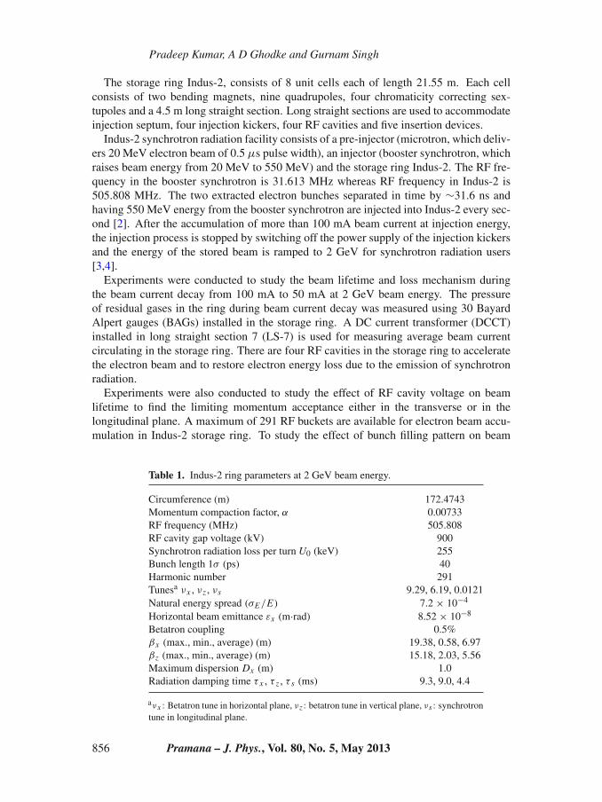
The storage ring Indus-2, consists of 8 unit cells each of length 21.55 m. Each cellconsists of two bending magnets, nine quadrupoles, four chromaticity correcting sex-tupoles and a 4.5 m long straight section. Long straight sections are used to accommodateinjection septum, four injection kickers, four RF cavities and five insertion devices.
Indus-2 synchrotron radiation facility consists of a pre-injector (microtron, which deliv-ers 20 MeV electron beam of 0.5 μs pulse width), an injector (booster synchrotron, whichraises beam energy from 20 MeV to 550 MeV) and the storage ring Indus-2. The RF fre-quency in the booster synchrotron is 31.613 MHz whereas RF frequency in Indus-2 is505.808 MHz. The two extracted electron bunches separated in time by ∼31.6 ns andhaving 550 MeV energy from the booster synchrotron are injected into Indus-2 every sec-ond [2]. After the accumulation of more than 100 mA beam current at injection energy,the injection process is stopped by switching off the power supply of the injection kickersand the energy of the stored beam is ramped to 2 GeV for synchrotron radiation users[3,4].
Experiments were conducted to study the beam lifetime and loss mechanism duringthe beam current decay from 100 mA to 50 mA at 2 GeV beam energy. The pressureof residual gases in the ring during beam current decay was measured using 30 BayardAlpert gauges (BAGs) installed in the storage ring. A DC current transformer (DCCT)installed in long straight section 7 (LS-7) is used for measuring average beam currentcirculating in the storage ring. There are four RF cavities in the storage ring to acceleratethe electron beam and to restore electron energy loss due to the emission of synchrotronradiation.
Experiments were also conducted to study the effect of RF cavity voltage on beamlifetime to find the limiting momentum acceptance either in the transverse or in thelongitudinal plane. A maximum of 291 RF buckets are available for electron beam accu-mulation in Indus-2 storage ring. To study the effect of bunch filling pattern on beam
Table 1. Indus-2 ring parameters at 2 GeV beam energy.
Circumference (m) 172.4743Momentum compaction factor, α 0.00733RF frequency (MHz) 505.808RF cavity gap voltage (kV) 900Synchrotron radiation loss per turn U0 (keV) 255Bunch length 1σ (ps) 40Harmonic number 291Tunesa νx , νz , νs 9.29, 6.19, 0.0121Natural energy spread (σE/E) 7.2 × 10⁻⁴
Horizontal beam emittance εx (m·rad) 8.52 × 10⁻⁸
Betatron coupling 0.5%βx (max., min., average) (m) 19.38, 0.58, 6.97βz (max., min., average) (m) 15.18, 2.03, 5.56Maximum dispersion Dx (m) 1.0Radiation damping time τ x , τ z , τ s (ms) 9.3, 9.0, 4.4
aνx : Betatron tune in horizontal plane, νz : betatron tune in vertical plane, νs : synchrotrontune in longitudinal plane.
856 Pramana – J. Phys., Vol. 80, No. 5, May 2013

Beam lifetime measurement and analysis in Indus-2 electron storage ring
lifetime, experiments were conducted by accumulating electron beam current uniformlyin all the 291 RF buckets and also accumulating the same amount of current in two-thirdof the RF buckets keeping the rest empty. During all these experiments, safety shuttersof all working beamlines (open for synchrotron radiation users) were kept closed to avoidany variation in storage ring pressure through beamlines.
An equation of stable beam current decay is evolved that closely follows the observedbeam current decay pattern. It shows that the beam is stable and the beam current decay isdue to the beam–gas scattering and electron–electron scattering within a bunch. An anal-ysis was carried out using analytical formulations to estimate the vacuum, Touschek andtotal beam lifetimes with existing vacuum pressure and applied RF cavity voltages. Theestimated vacuum, Touschek and total beam lifetimes are compared with the measuredbeam lifetimes. The parameters used in the analysis are given in table 1.
2. Factors affecting beam lifetime
In an electron storage ring, the stored beam current gradually decreases because elec-trons are constantly lost due to scattering in the finite aperture available for their betatronand synchrotron oscillations. There are four major beam loss mechanisms [5–7]: (1)elastic collisions between electrons and nuclei of the residual gas atoms (Coulombscattering), (2) inelastic collisions between electrons and nuclei of the residual gas atoms(bremsstrahlung), (3) collisions between electrons within a bunch (Touschek scattering)and (4) synchrotron radiation emission (quantum excitation).
Quantum excitation due to synchrotron radiation emission contributes only when theacceptance of the storage ring is smaller than about seven times the beam dimensions.The transverse and longitudinal acceptances of Indus-2 electron storage ring are muchlarger than this limit. So the contribution of quantum excitation in the total beam lifetimeis negligible.
As electrons circulate in an electron storage ring they collide within the bunch and alsowith residual gas atoms. The rate of particle loss can be written as [8],
−dI
dt= aI + bI 2, (1)
where a and b are the arbitrary constants.After integration of eq. (1) we get,
I (t) = I0
eat + (b/a) I0 (eat − 1), (2)
where I0 is the initial stored beam current at time t = 0.
3. Beam lifetime experiments
3.1 Beam current decay and lifetime with 900 kV RF cavity voltage
Approximately 100 mA beam current at 2 GeV beam energy was stored with 900 kVtotal RF cavity peak voltage by energizing all four RF cavities at the same voltage.In this condition electron beam was accumulated uniformly in all the 291 RF buckets
Pramana – J. Phys., Vol. 80, No. 5, May 2013 857

Pradeep Kumar, A D Ghodke and Gurnam Singh
45
60
75
90
105B
eam
cur
rent
(m
A)
Time (hours)(a) (b)0 5 10 15 20 50 60 70 80 90 100 110
21
24
27
30
33
Bea
m li
fetim
e (h
ours
)
Beam current (mA)
Figure 1. (a) Measured beam current decay and (b) beam lifetime at different storedbeam current during beam current decay.
(∼0.34 mA, equivalent to 1.23 × 10⁹ electrons in a bunch per bucket). Beam currentdecay from 100 to 50 mA stored beam current was measured and is shown in figure 1a.During the beam current decay, vacuum pressure in the ring was also measured. Betatronand synchrotron tunes during the beam current decay remained unchanged. It shows thatthe beam optics also remains unchanged during the experiments. From the beam cur-rent decay data, decay rate (−dI/dt) and instantaneous beam lifetime [−I/(dI/dt)] wereestimated. The beam lifetime at different stored beam current is shown in figure 1b.
3.2 Beam current decay and lifetime with 750 kV RF cavity voltage
Coulomb scattering of charged particles in a stored beam causes an exchange of energybetween transverse and longitudinal oscillations. Due to this scattering, a small transversemomentum can be transferred to a large longitudinal momentum. The amplification of themomentum change is a relativistic effect so that the change in the longitudinal momentumof the electron is increased by the Lorentz factor γ . A momentum change to a valueoutside the momentum acceptance of the storage ring will cause loss of electron, leading
0 1 2 3 484
87
90
93
96
99
102
0 1 2 3 484
87
90
93
96
99
102
750kV
900kV
Bea
m c
urre
nt (
mA
)
Time (hours)(a) (b)84 88 92 96 100 104
19
20
21
22
23
24
84 88 92 96 100 104
19
20
21
22
23
24
Bea
m li
fetim
e (h
ours
)
Beam current (mA)
750kV
900kV
Figure 2. (a) Beam current decay at different RF voltages and (b) beam lifetime atdifferent stored current at different RF voltages.
858 Pramana – J. Phys., Vol. 80, No. 5, May 2013

Beam lifetime measurement and analysis in Indus-2 electron storage ring
Figure 3. (a) Wall current monitor signal at 100 mA stored current when all 291 RFbuckets are filled and (b) wall current monitor signal at 100 mA stored current whentwo-third of the RF buckets are filled.
to a finite Touschek lifetime. To study the limiting momentum acceptance, an experimentwas conducted with 750 kV RF cavity peak voltage. In this condition, a comparisonin beam current decay and beam lifetime from 102 to 85 mA with 750 and 900 kV RFvoltage are shown in figures 2a and 2b respectively. In this condition, all the 291 RFbuckets were filled uniformly. It shows that by increasing cavity voltage, RF acceptanceincreases leading to increase in beam lifetime.
Pramana – J. Phys., Vol. 80, No. 5, May 2013 859

Pradeep Kumar, A D Ghodke and Gurnam Singh
0 1 2 3 480
85
90
95
100
105
0 1 2 3 480
85
90
95
100
105
194 RF buckets
291 RF buckets
Bea
m c
urre
nt (
mA
)
Time (hours)(a) (b)84 88 92 96 100 104
17
18
19
20
21
84 88 92 96 100 104
17
18
19
20
21
194 RF buckets
291 RF buckets
Bea
m li
fetim
e (h
ours
)
Beam current (mA)
Figure 4. (a) Beam current decay and (b) beam lifetime when 291 and 194 RFbuckets were filled.
3.3 Beam current decay and lifetime in different bunch filling pattern
To study the effect of increase in the number of electrons in a bunch assuming that thevolume of the bunch remains the same (increase in bunch density, i.e. number of electronsin a bunch/volume), beam current was stored uniformly in two-third of the RF buckets(194) keeping the rest (97) empty. Stored beam current (∼100 mA) was filled uniformlyin 194 RF buckets (∼0.51 mA, equivalent to 1.85 × 10⁹ electrons in a bunch per bucket).The applied cavity peak voltage was 750 kV. The wall current monitor signal stored onCRO indicating the bunch filling pattern for 291 and 194 RF buckets filled are shown infigures 3a and 3b respectively. The beam current decay and beam lifetime in both casesat the same RF cavity peak voltage of 750 kV were compared and are shown in figures 4aand 4b respectively. The vacuum pressure during the beam current decay was measuredand found to be the same at the same stored beam current in both the cases.
4. Analysis of measured beam lifetime
From the measured beam current decay curve (figure 1a), we have tried to obtain anequation that follows the beam current decay pattern. Let us assume that the beam currentdecay is due to the beam–gas scattering and Touschek scattering. So the beam currentdecay rate should follow eq. (1).
We take 100 data points of the measured stored beam current Ii (i = 1, 2, ..., 100) andits decay rate − dIi
dt (say di ). Using the data of stored beam current and decay rate, a curvefitting of the form di = aIi + bI 2
i was generated. To estimate the coefficients a and b weuse the least square minimization method as follows:
error χ2(a, b) =100∑
i=1
[1
σi
(di − aIi − bI 2
i
)]2
, (3)
where σ i is the uncertainty in measured data.
860 Pramana – J. Phys., Vol. 80, No. 5, May 2013

Beam lifetime measurement and analysis in Indus-2 electron storage ring
For the minimization of χ2, put(∂χ2/∂a
) = 0 and(∂χ2/∂b
) = 0, and we findcoefficients a, b as
[ab
]=
⎡
⎢⎢⎢⎢⎣
100∑
i=1
I 2i
σ 2i
100∑
i=1
I 3i
σ 2i
100∑
i=1
I 3i
σ 2i
100∑
i=1
I 4i
σ 2i
⎤
⎥⎥⎥⎥⎦
−1 ⎡
⎢⎢⎢⎢⎣
100∑
i=1
di Ii
σ 2i
100∑
i=1
di I 2i
σ 2i
⎤
⎥⎥⎥⎥⎦,
[ab
]= 1
�×
⎡
⎢⎢⎢⎢⎣
100∑
i=1
I 4i
σ 2i
−100∑
i=1
I 3i
σ 2i
−100∑
i=1
I 3i
σ 2i
100∑
i=1
I 2i
σ 2i
⎤
⎥⎥⎥⎥⎦×
⎡
⎢⎢⎢⎢⎣
100∑
i=1
di Ii
σ 2i
100∑
i=1
di I 2i
σ 2i
⎤
⎥⎥⎥⎥⎦,
� =
∣∣∣∣∣∣∣∣∣∣
100∑
i=1
I 2i
σ 2i
100∑
i=1
I 3i
σ 2i
100∑
i=1
I 3i
σ 2i
100∑
i=1
I 4i
σ 2i
∣∣∣∣∣∣∣∣∣∣
=100∑
i=1
I 2i
σ 2i
100∑
i=1
I 4i
σ 2i
−(
100∑
i=1
I 3i
σ 2i
)2
.
From this expression we get a and b as
a = 1
�×
[100∑
i=1
I 4i
σ 2i
100∑
i=1
di Ii
σ 2i
−100∑
i=1
I 3i
σ 2i
100∑
i=1
di I 2i
σ 2i
], (4)
b = 1
�×
[100∑
i=1
I 2i
σ 2i
100∑
i=1
di I 2i
σ 2i
−100∑
i=1
I 3i
σ 2i
100∑
i=1
di Ii
σ 2i
]. (5)
We take beam current data using the same DC current transformer (DCCT). So uncertaintyin all measurements is assumed to be the same and so σ i = σ and is given [9] as
σ 2 = 1
N − m
100∑
i=1
[di − aIi − bI 2
i
]2, (6)
where N − m is the number of degrees of freedom which is equal to the number ofmeasurements minus the number of parameters determined from the fit. In our case N =100, m = 2 and so the number of degree of freedom is 98.
Putting the measured data in eqs (4)–(6) we get
σ = 1.6788 × 10⁻⁵ mA/s
a = 4.3943 × 10⁻⁶ /s
b = 8.4766 × 10⁻⁸ /mA · s
χ2 = 98.
Pramana – J. Phys., Vol. 80, No. 5, May 2013 861

Pradeep Kumar, A D Ghodke and Gurnam Singh
Estimation of uncertainties in the coefficients a and b
In order to find the uncertainty in the estimation of the coefficients a and b, errorpropagation method [9] is used. Uncertainty is given as
σ 2a =
100∑
i=1
[σ 2
i (∂a/∂di )2] and σ 2
b =100∑
i=1
[σ 2
i (∂b/∂di )2].
Estimating partial derivative of a and b with respect to di , we get
σ 2a = 1
�×
100∑
i=1
I 4i
σ 2i
, (7)
σ 2b = 1
�×
100∑
i=1
I 2i
σ 2i
. (8)
Using the measured data we get uncertainty σ a and σ b in a and b respectively.
σa = ±1.2829 × 10⁻⁷/s,
σb = ±1.5524 × 10⁻⁹/mA·s.
Equation of beam current decay with uncertainty in coefficients a and b is written as
−dIi
dt= (
4.3943 × 10⁻⁶ ± 1.2829 × 10⁻⁷)Ii
+ (8.4766 × 10⁻⁸ ± 1.5524 × 10⁻⁹
)I 2i . (9)
The instantaneous beam lifetime τ is estimated as [−Ii/(dIi/dt)] from the measuredbeam current decay data. Due to the uncertainty in coefficients a and b, there is ∼2.5%uncertainty in the measured beam lifetime.
The measured beam current decay rate and fitted decay rate curve with coefficients aand b at different stored beam current is shown in figure 5a.
50 60 70 80 90 100 110
0.0004
0.0006
0.0008
0.0010
0.0012
0.0014 Measured datafitted with coefficients a and b-dI/dt=0.4394x10-5×I+0.8476x10-7×I2
deca
y ra
te -
dI/d
t(m
A/s
econ
d)
Beam current I(mA)(a) (b)0 5 10 15 20
50
60
70
80
90
100Measured beam current decaydecay curve with coefficients a and b
Bea
m c
urre
nt (
mA
)
Time (hours)
Figure 5. (a) Measured beam current decay rate and fitted curve at different beamcurrent and (b) measured beam current decay and decay curve with coefficients aand b.
862 Pramana – J. Phys., Vol. 80, No. 5, May 2013
Beam lifetime measurement and analysis in Indus-2 electron storage ring
Substituting the values of coefficients a and b in eq. (2) and initial beam current I0 =102 mA, the measured beam current decay and current decay curve using coefficients aand b with time are shown in figure 5b.
It is seen from figures 5a and 5b that all the points in the measured beam current decaycurve satisfies the fitted equation of the curve with coefficients a and b. So the measuredbeam decay is due to the beam–gas scattering and Touschek scattering only.
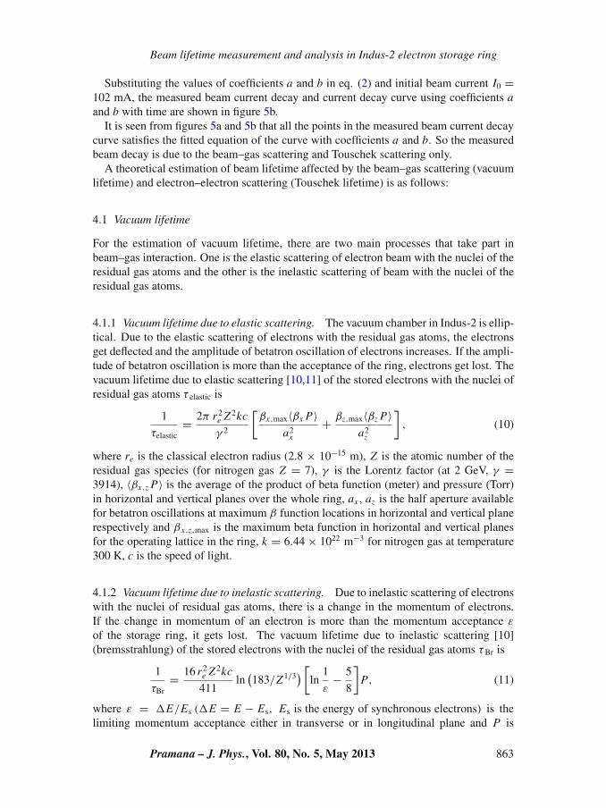
A theoretical estimation of beam lifetime affected by the beam–gas scattering (vacuumlifetime) and electron–electron scattering (Touschek lifetime) is as follows:
4.1 Vacuum lifetime
For the estimation of vacuum lifetime, there are two main processes that take part inbeam–gas interaction. One is the elastic scattering of electron beam with the nuclei of theresidual gas atoms and the other is the inelastic scattering of beam with the nuclei of theresidual gas atoms.
4.1.1 Vacuum lifetime due to elastic scattering. The vacuum chamber in Indus-2 is ellip-tical. Due to the elastic scattering of electrons with the residual gas atoms, the electronsget deflected and the amplitude of betatron oscillation of electrons increases. If the ampli-tude of betatron oscillation is more than the acceptance of the ring, electrons get lost. Thevacuum lifetime due to elastic scattering [10,11] of the stored electrons with the nuclei ofresidual gas atoms τ elastic is
1
τelastic= 2π r2
e Z2kc
γ 2
[βx,max〈βx P〉
a2x
+ βz,max〈βz P〉a2
z
], (10)
where re is the classical electron radius (2.8 × 10⁻¹⁵ m), Z is the atomic number of theresidual gas species (for nitrogen gas Z = 7), γ is the Lorentz factor (at 2 GeV, γ =3914), 〈βx,z P〉 is the average of the product of beta function (meter) and pressure (Torr)in horizontal and vertical planes over the whole ring, ax , az is the half aperture availablefor betatron oscillations at maximum β function locations in horizontal and vertical planerespectively and βx,z,max is the maximum beta function in horizontal and vertical planesfor the operating lattice in the ring, k = 6.44 × 10²² m−3 for nitrogen gas at temperature300 K, c is the speed of light.
4.1.2 Vacuum lifetime due to inelastic scattering. Due to inelastic scattering of electronswith the nuclei of residual gas atoms, there is a change in the momentum of electrons.If the change in momentum of an electron is more than the momentum acceptance ε
of the storage ring, it gets lost. The vacuum lifetime due to inelastic scattering [10](bremsstrahlung) of the stored electrons with the nuclei of the residual gas atoms τBr is
1
τBr= 16 r2
e Z2kc
411ln
(183/Z1/3
) [ln
1
ε− 5
8
]P, (11)
where ε = �E/Es (�E = E − Es, Es is the energy of synchronous electrons) is thelimiting momentum acceptance either in transverse or in longitudinal plane and P is
Pramana – J. Phys., Vol. 80, No. 5, May 2013 863

Pradeep Kumar, A D Ghodke and Gurnam Singh
the average pressure in the storage ring. From the experiment of RF voltage effect onbeam lifetime, it is clear that by increasing cavity voltage from 750 kV to 900 kV, thereis an increase in beam lifetime and so the momentum acceptance due to RF (longitudinalplane) is a limiting factor for electron loss. For 900 kV, the calculated RF accep-tance ε = ±0.9% (�E = ±0.9% of synchronous energy) was used for beam lifetimeestimation. The RF acceptance is reduced to 0.76% for 750 kV RF voltage.
For the estimation of vacuum lifetime due to elastic and inelastic scattering, averagepressure P , average of βx P and β z P over the whole ring was estimated as follows:
4.1.3 Estimation of average pressure P̄ and average of βx P and βz P. The resid-ual gas pressure in Indus-2 was measured using thirty Bayard Alpert ionization gauges(BAGs) calibrated for nitrogen equivalent gas pressure installed in the storage ring. Thelocation of the BAGs and the vacuum pumps in one unit cell is shown in figure 6.
From the measured vacuum pressure data at thirty BAGs in the ring, a vacuum pressureprofile along the beam path was generated. From the pressure profile, average pressure P̄was estimated as
P̄ =∑n
i=1 Pili∑ni=1 li
, i = 1, 2, 3, . . . , n,
where Pi is the measured pressure at location i representing the vacuum condition overthe length li from −li/2 to +li/2 over which Pi is taken as constant. The average pressureduring beam current decay from 100 mA to 50 mA in steps of 10 mA is shown in figure 7.The linear curve fit of the average pressure graph shows that the average pressure withoutbeam (I = 0) is 0.55 × 10⁻⁹ Torr, which is close to the real measured value 0.60 ×10⁻⁹ Torr in the storage ring. The horizontal and vertical beta functions βx and β z ofthe operating lattice were measured using quadrupole scan method. The measured betafunction in the ring was found to be very close to the theoretical operating value. So wehave used the theoretical value of beta functions for the analysis. The lattice functions βx
and β z in one unit cell are shown in figure 8. From the pressure profile and beta functions,
Figure 6. BA Gauge and vacuum pump locations in one unit cell.
864 Pramana – J. Phys., Vol. 80, No. 5, May 2013

Beam lifetime measurement and analysis in Indus-2 electron storage ring
50 60 70 80 90 100
0.84
0.90
0.96
1.02
1.08
1.14
1.20
P(n.Torr)= 0.55+0.00663*I
Measured data Linear fit of measured data
Vac
uum
pre
ssur
e (n
Tor
r)
Beam current (mA)
Figure 7. Measured vacuum pressure during the beam current decay.
average value of βx P and β z P in the whole ring was calculated. The average value ofβx P and β z P during beam current decay is shown in figure 9.
4.1.4 Estimation of available aperture for beam motion [11]. The physical apertureavailable in the vacuum chamber of Indus-2 is ±32 mm (outward and inward from thecentre of the beam axis) in the horizontal plane and ±17 mm (upward and downwardfrom the centre of the beam axis) in the vertical plane. Due to the presence of sex-tupoles, magnet multipole errors and magnet misalignment errors, aperture available forstable motion of the electrons, which is known as dynamic aperture, is reduced. A sin-gle particle tracking in the presence of magnet multipole errors and magnet misalignmenterrors was carried out to find the aperture available for stable beam motion at maximum
0 5 10 15 20 25-5
0
5
10
15
20
z
x
QD
QF
QD
BMQF
QD
QFBM
QD
QF
QD
Latti
ce fu
nctio
ns
x, z (
m)
Path length (m)
Figure 8. Beta functions βx , βz in one unit cell. QD is the defocussing quadrupole,QF is the focussing quadrupole and BM is the bending magnet.
Pramana – J. Phys., Vol. 80, No. 5, May 2013 865

Pradeep Kumar, A D Ghodke and Gurnam Singh
50 60 70 80 90 100
5
6
7
8
9
<z.P>
<x.P>
<.P
> (
m.n
Tor
r)
Beam current (mA)
Figure 9. Variation of 〈βx P〉, 〈βz P〉 during the beam current decay.
beta function location. The tracking studies show that aperture available at βmax locationincluding closed orbit (closed orbit was corrected to less than 1 mm rms in both horizon-tal and vertical plane) is ±18 and ±12 mm in horizontal and vertical plane respectively.By using these values of the dynamic apertures, vacuum lifetime due to elastic scatteringusing eq. (10) was estimated.
The estimation of vacuum lifetime due to elastic scattering τ elastic, and due to inelasticscattering τBr, was carried out using eqs (10) and (11).
Total vacuum lifetime τ v is given by
1
τv= 1
τelastic+ 1
τBr. (12)
The estimated total vacuum lifetime τ v along with the contribution of elastic scatteringτ elastic, inelastic scattering τBr, assuming nitrogen equivalent gas pressure during beamcurrent decay is shown in figure 10.
4.2 Estimation of Touschek lifetime (τtous)
The Touschek lifetime (τ tous) [12,13] due to electrons scattering within a bunch is givenby
τtous = γ 3σ ′xε
2V√π r2
e cN ln 2C(ζ ), (13)
where
V = 8 π3/2σxσzσs, ζ =(
ε
γ σ ′x
)2
,
V is the bunch volume, σ x , σ z and σ s are the horizontal, vertical and longitudinal rmsbeam sizes respectively, ε is the limiting momentum acceptance either in transverse or in
866 Pramana – J. Phys., Vol. 80, No. 5, May 2013

Beam lifetime measurement and analysis in Indus-2 electron storage ring
50 60 70 80 90 100
30
40
50
60
70
80
90
100
v
Br
elastic
Vac
uum
life
time
(hou
rs)
Beam current (mA)
Figure 10. Vacuum lifetime during beam current decay.
longitudinal plane, σ ′x is the horizontal divergence of the electron beam, N is the number
of electrons per bunch where
C(ζ ) = −3
2e−ζ + ζ
2
∫ ∞
ζ
ln u
ue−udu + 1
2(3ζ − ζ ln ζ + 2)
∫ ∞
ζ
e−u
udu.
For the estimation of Touschek lifetime, the particle tracking code ELEGANT [14]was used. For Indus-2, the momentum acceptance [15] for positive and negative off-momentum electrons was estimated by six-dimension particle tracking [16]. The trackingresult shows that the momentum acceptance is limited by RF acceptance, for RF voltage900 kV, ε is ±0.9%. It was also confirmed experimentally by studying the effect of RFvoltage on the beam lifetime.
The motion of the electrons is stable inside the RF bucket. If the momentum changeduring Touschek scattering in two electrons is more than the RF acceptance ε, the elec-trons will come out of the RF bucket and is lost. The synchronous phase φs is the phase
0 60 120 180 240 300
-0.0105
-0.0070
-0.0035
0.0000
0.0035
0.0070
0.0105
0 60 120 180 240 300
-0.0105
-0.0070
-0.0035
0.0000
0.0035
0.0070
0.0105 900kV
750kV
Phase (degree)
Figure 11. RF buckets for different RF voltages.
Pramana – J. Phys., Vol. 80, No. 5, May 2013 867

Pradeep Kumar, A D Ghodke and Gurnam Singh
50 60 70 80 90 100
120
150
180
210
240
Tou
sche
k lif
etim
e (h
ours
)
Beam current (mA)
Figure 12. Touschek lifetime during beam current decay.
of the right energy electron called synchronous electron, φs = sin−1 (U0/eV ) where U0 isthe energy loss per turn due to synchrotron radiation and V is the applied RF cavity peakvoltage. For RF cavity voltage = 900 kV, φs = 163.7◦ whereas for 750 kV it is 160.5◦.The RF buckets in Indus-2 at 750 and 900 kV RF cavity voltages are shown in figure 11.
For estimating the vertical beam size σ z , betatron coupling (ratio of the vertical beamemittance to the horizontal beam emittance) was measured using minimum tune separa-tion method and found to be 0.5% [17]. Using 0.9% RF momentum acceptance and 0.5%measured betatron coupling, the estimated Touschek lifetime for beam current decay from100 to 50 mA using formula (13) is shown in figure 12.
The total beam lifetime τ is given by
1
τ= 1
τv+ 1
τtous. (14)
50 60 70 80 90 100
21
24
27
30
33 _____Measured beam lifetime..........Estimated beam lifetime
Bea
m li
fetim
e (h
ours
)
Beam current (mA)
Figure 13. Comparison of the estimated and the measured beam lifetime.
868 Pramana – J. Phys., Vol. 80, No. 5, May 2013

Beam lifetime measurement and analysis in Indus-2 electron storage ring
A comparison of the estimated beam lifetime and the measured beam lifetime duringbeam current decay is shown in figure 13.
The theoretical analysis shows that the estimated beam lifetime using analytical formu-lations is close to the measured beam lifetime at different stored beam current during itsnatural decay.
5. Estimation of vacuum and Touschek lifetimes from measured beam lifetime
From the measured beam lifetime, the contribution of vacuum and Touschek lifetimeswas determined using measured vacuum pressure. In the above experiment, we havetaken beam current decay from 102 to 50 mA, the measured beam lifetime at 100 mAwas 21.6 h and at 50 mA it was 32 h.
Let (τ tous)100 mA and (τ tous)50 mA be the values of Touschek lifetime at 100 mA and50 mA stored beam current respectively. From Touschek lifetime formula (13), we seethat if the volume of the bunch is the same (no change in horizontal, vertical rms beamsize and rms bunch length during beam current decay) then Touschek lifetime is inverselyproportional to the number of electrons in the bunch. The number of electrons in onebunch at 50 mA beam current will be half the number of electrons at 100 mA current. Sothe Touschek lifetime at 50 mA stored current will be twice that of the Touschek lifetimeat 100 mA stored current and
(τtous)50 mA = 2 × (τtous)100 mA. (15)
Let (τ v)100 mA and (τ v)50 mA be the vacuum lifetimes at 100 mA and 50 mA stored beamcurrent respectively. The measured average vacuum pressure at 100 mA (P100 mA) is 1.2nTorr and at 50 mA (P50 mA) is 0.87 nTorr.
We know that the vacuum lifetime τ v is inversely proportional to the pressure in thering. So
(τv)100 mA
(τv)50 mA= P50 mA
P100 mA= 0.87
1.2= 0.725 ⇒ (τv)100 mA = 0.725 (τv)50 mA.
(16)
If τ 100 mA and τ 50 mA are the total beam lifetime at 100 mA and 50 mA stored beamcurrent respectively, then
1
τ100 mA= 1
(τv)100 mA+ 1
(τtous)100 mA
and
1
τ50 mA= 1
(τv)50 mA+ 1
(τtous)50 mA. (17)
Using the conditions (τtous)50 mA = 2(τtous)100 mA and (τv)100 mA = 0.725(τv)50 mA, wefind that
(τv)100 mA = 27.7 h and (τtous)100 mA = 98 h,
(τv)50 mA = 38.2 h and (τtous)50 mA = 196 h.
Pramana – J. Phys., Vol. 80, No. 5, May 2013 869

Pradeep Kumar, A D Ghodke and Gurnam Singh
The vacuum lifetime and Touschek lifetime estimated for 50 and 100 mA stored cur-rent is close to the value estimated from analytical formulations using measured vacuumpressure, cavity voltage and horizontal and vertical apertures.
Accumulating electron beam in different bunch filling pattern is also carried out to findthe contribution of Touschek and vacuum lifetimes in total measured beam lifetime. Itwas found experimentally that at the same stored current, average pressure remains thesame when either all or two-third of the RF buckets are filled. So the vacuum lifetimeat the same stored beam current in both the cases is the same. From the measured beamlifetime at 100 mA in both cases and considering vacuum lifetime the same, vacuum andTouschek lifetimes at 100 mA stored current was estimated using formula (14) and foundto be close to the estimated results from analytical formulations.
6. Conclusions
Beam lifetime studies have been conducted in Indus-2 storage ring at 2 GeV beamenergy. Beam lifetime was measured during beam current decay from stored beam cur-rent 100 mA to 50 mA. An equation of the stable beam current decay was evolved thatclosely follows the observed beam current decay pattern. It shows that the beam is stableand the beam current decay is only from the beam–gas scattering and electron–electronscattering within a bunch. The effect of RF cavity voltage on beam lifetime was studied.It shows that the RF acceptance is a major limiting momentum acceptance in the stor-age ring. The effect of Touschek scattering was also studied by accumulating beam withdifferent bunch filling patterns. To analyse the measured beam lifetimes, an estimationof vacuum and Touschek lifetimes was carried out with measured gas pressure, appliedRF cavity voltage and apertures for beam motion using analytical formulations. From themeasured beam lifetime, contribution of vacuum lifetime and Touschek lifetime at 50 mAand 100 mA stored beam current was estimated. The vacuum, Touschek and total beamlifetimes estimated by analytic formulations are found to be close to the measured beamlifetimes. The effect of different bunch filling pattern on beam lifetime was also studiedto separate the contribution of vacuum and Touschek lifetimes from the measured beamlifetime. With the reduction in residual gas pressure, closed orbit correction and RF phaseoptimization with electron beam, the beam lifetime in Indus-2 was increased to ∼22 h at100 mA stored beam current. There is a scope for improvement in beam lifetime with thereduction in residual gas pressure and increase in applied RF cavity gap voltage in future.
Acknowledgements
Authors are thankful to Dr P D Gupta, Director, RRCAT, Dr Pitamber Singh, Head,Ion Accelerator Development Division, BARC, and Mr P R Hannurkar, Head, IOAPDD,for their encouragement and support for this work. The authors would like to thank DrM Borland, APS Lab for providing help and for the useful discussion to implement anduse ELEGANT code for the simulation of Touschek lifetime. They would also like tothank UHV group and Indus Accelerator Complex shift crewmembers for their help inconducting the beam experiments.
870 Pramana – J. Phys., Vol. 80, No. 5, May 2013

Beam lifetime measurement and analysis in Indus-2 electron storage ring
References
[1] D D Bhawalkar, G Singh and R V Nandedkar, Pramana – J. Phys. 50(6), 467 (1998)[2] D Angal-Kalinin and G Singh, Proceedings of EPAC 2002 (Paris, France) p. 641[3] A D Ghodke, ICFA Newsletter, No. 4, December 2006, p. 77[4] V C Sahani, Proceedings of APAC-2007 (Indore, India)[5] X Huang and J Corbett, Nucl. Instrum. Methods A 629, 31 (2011)[6] J Le Duff, Nucl. Instrum. Methods A 239, 83 (1985)[7] H Wiedemann, Particle accelerator physics third edition (Springer-Verlag, Berlin, 2007)[8] J Corbett, X Huang, M Lee and P Lui, Proceedings of PAC 2007, p. 4153[9] Philip R Bevington and D Keith Robinson, Data reduction and error analysis for the physical
sciences second edition (McGraw-Hill, New York, 1992)[10] Michael S Zisman, S Chattopadhyay and J J Bisognano, ZAP User’s Manual, LBL-21270,
ESG-15, December 1986[11] Erik Wallen, Nucl. Instrum. Methods A 508, 487 (2003)[12] Jim Murphy, Synchrotron light source data book, BNL 42333, May 1996[13] Tae-Yeon Lee, Jinhyuk Choi and H S Kang, Nucl. Instrum. Methods A 554, 85 (2005)[14] M Borland, ELEGANT: A flexible SDDS-compliant code for accelerator simulation[15] C Steier, D Robin, L Nadolski, W Decking, Y Wu and J Laskar, Phys. Rev. E 65, 056506
(2002)[16] M Borland, Momentum aperture determination with ELEGANT, OAG-TN-2006[17] A D Ghodke, Riyasat Husain, Pradeep Kumar, Surendra Yadav and T A Puntambekar, Rev.
Sci. Instrum. 83, 103303 (2012)
Pramana – J. Phys., Vol. 80, No. 5, May 2013 871


![Low Voltage Electron Microscope - Melbourne...PROJECTION LENS electrostatic double lens ELECTRON GUN SE Cathode ZrO/W[100] Current density 0.3 mAsr-1 Lifetime >2,000 hours TEM IMAGE](https://img.pdfslide.us/doc/110x75/5f3bb4292356f6711a41ed06/low-voltage-electron-microscope-melbourne-projection-lens-electrostatic-double.jpg)