Embed Size (px)
Citation preview

Rev. 13.03.01
BEAM 201
User Manual / Instrucciones de Usuario
STATEMENTThe product is good packing when ship out the factory. All users should strictly abide by the warnings and nstructions stated in this manual, any damage and results due to misuse and the neglect of this operating manual will be excluded from the deal responsibility this manual will not informed in additionally if have technical changes.
DISPLAY PRODUCTION DESCRIPTIONThank you for choose this B200 products, this model is the moving head light which is the latest development of the smart, efficient products, beautiful shape, smooth R & D, combined with the advanced technology of today's stage lighting products with international advanced electronic control technology and excellent user-friendly industrial design , fully comply with CE standard, accepted international standard DMX512 signal mode.This moving head lights, use ceramic luminescent film reflector as a condenser system, coupled with the high-quality optical lens components, broadband voltage, a clear pattern, sharp and uniform output light efficiency. Intelligent LED display module, the English language selection mode, intuitive operating menu, shortcut.B200, have 16/20 international standard DMX512 channels optional Horizontal scan: 540 ° vertical scanning 270 ° (16bit precision scanning) electronic correction, dot-matrix display, four touch switch LCD + single-Key flying shuttle can spin. The can be inverted 180 °, the color wheel is combined with white and 14 colors. Gobo wheel: 7 patterns + white effect round by eight prism and atomization function. 0-100% mechanical dimmer, support mechanical strobe and variable strobe effect, strobe macro function. The optical system of the lens group electric focusing, the beam angle of 0 to 4 ° with overheating protection function.Moving head lights are widely used in television, disco, dance halls, nightclubs, large-scale performances and other professional venues
1. PRODUCT INTRODUCTION
Size:395(L)×287(W)×495(H)mmNet Weight:17.5KG
2. SAFETY INFORMATION
Safety warning messageThis product is only suitable for professional use, and does not apply to security for other purposes.After you got the lights, please check the package whether have any damage caused by transportation. If there is any damage, do not use this fixture, and please contact the dealer or
1.1 BEAM SIZE
BEAM 201 User Manual/Manual de uso Page 1
EN
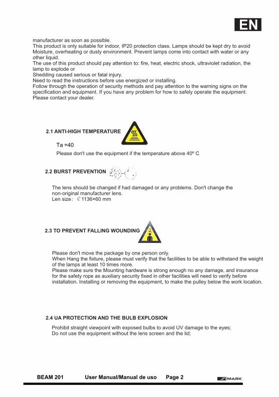
Ta =40
manufacturer as soon as possible.This product is only suitable for indoor, IP20 protection class. Lamps should be kept dry to avoid Moisture, overheating or dusty environment. Prevent lamps come into contact with water or any other liquid.The use of this product should pay attention to: fire, heat, electric shock, ultraviolet radiation, the lamp to explode orShedding caused serious or fatal injury. Need to read the instructions before use energized or installing. Follow through the operation of security methods and pay attention to the warning signs on the specification and equipment. If you have any problem for how to safely operate the equipment. Please contact your dealer.
Please don't use the equipment if the temperature above 40º C
The lens should be changed if had damaged or any problems. Don't change the non-original manufacturer lens.Len size:¢1136×60 mm
Please don't move the package by one person only.When Hang the fixture, please must verify that the facilities to be able to withstand the weight of the lamps at least 10 times more.Please make sure the Mounting hardware is strong enough no any damage, and insurance for the safety rope as auxiliary security fixed in other facilities will need to verify before installation. Installing or removing the equipment, to make the pulley below the work location.
Prohibit straight viewpoint with exposed bulbs to avoid UV damage to the eyes;Do not use the equipment without the lens screen and the lid;
2.1 ANTI-HIGH TEMPERATURE
2.2 BURST PREVENTION
2.3 TO PREVENT FALLING WOUNDING
2.4 UA PROTECTION AND THE BULB EXPLOSION
BEAM 201 User Manual/Manual de uso Page 2
EN
3. PACKAGE
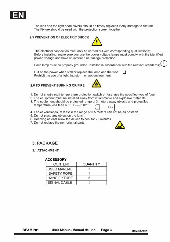
ACCESSORY
CONTENT QUANTITY
1
1
HANG FIXTURE 2
SIGNAL CABLE 1
The lens and the light head covers should be timely replaced if any damage to ruptureThe Fixture should be used with the protection screen together.
The electrical connection must only be carried out with corresponding qualifications;Before installing, make sure you use the power voltage lamps must comply with the identified power, voltage and have an overload or leakage protection;
Each lamp must be properly grounded, installed in accordance with the relevant standards;
Cut off the power when stall or replace the lamp and the fuse;Prohibit the use of a lightning storm or wet environment.
1. Do not short-circuit temperature protection switch or fuse, use the specified type of fuse.2. The equipment must be installed away from inflammable and explosive materials.3. The equipment should be projected range of 3 meters away objects and projectiles temperature less than 60 ° C; ---- 3.0m.
4. Fan or ventilation, at least in the range of 0.5 meters can not be an obstacle.5. Do not place any object on the lens.6. Handling at least allow the device to cool for 20 minutes.7. Do not replace the non-original parts.
2.5 PREVENTION OF ELECTRIC SHOCK
2.6 TO PREVENT BURNING OR FIRE
3.1 ATTACHMENT
USER MANUAL
SAFETY ROPE
BEAM 201 User Manual/Manual de uso Page 3
EN
PACAKGE SIZE
FLY-CASE 2 IN 1 985*450*735
1. Before packed, make sure power is off, and wait for at least 20mins for cooling down.
2. Before clean the fixture, make sure X, Y axis protect lock closed.
3. After packed by plastic bag, high-lift the fixture with two handles besides the product. put
the product into the fly-case up-side-down.
4. After packed the product, put the accessory into the accessory case, then closed and lock the
fly-case.
5. Fly-case only up stacked two layers. Prohibited upside down
In order to protect the light, there is a protect lock; During the transport , the lock will closed keeping the item in safety state.
Note: Before unpacking check the damage is whether due to the transportation or not, if you find any such damage, please do not use this item, and contact with the dealer or manufacturer as soon as possible.
1. Open the fly-case, and discover the inside plastic bag.2. High-lift the product by two handles beside the bottom base and move it out.3. Before power on, make sure you have opened the X, Y axis lock!
BEAM 201 can be placed on the stage, or mounted in an arbitrary direction of the truss. Two fast locks system could fix the item easily
1. Before installation must verify the fast lock is keep in good state, and can withstand at least 10 times the weight of product. Verify that the truss can withstand at least 10 times of the total weight of the product and accessory equipments.2. Fix the hang fixture into the hole, which located on the base of the price. Seize handle of fasteners, clockwise rotate 1/4 turn and lock. Installed other one fastener in the same method. 3. Using the safety cable which can withstand 10 times the weight of the equipment.
4. INSTALL STANDARD
3.2 TRANSPORT PROTECT LOCK
3.3 ABOUT PACK STAGE
3.4 UNPACKING
4.1 INSTALL LOCK
4.2 EQUIPMENT FIXED
BEAM 201 User Manual/Manual de uso Page 4
EN
5. ALTERNATING CURRENT POWER SUPPLY
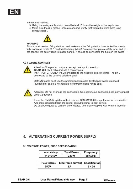
Input Voltage Total Power Frequency
110~240V 230W 50/60Hz
Fuse voltage Electronic current Specification
250V 6A 5×20
in the same method. 3. Using the safety cable which can withstand 10 times the weight of the equipment. 4. Make sure the X,Y protect locks are opened, Verify that within 3 meters there is no combustibles .
WARNINGFixture must use two fixing devices, and make sure the fixing device have locked! And only fully clockwise rotate 90 ° can lock the hang fixture! Do remember plus a safety rope, and do not connect the safety rope to plastic handle. It should be connect to the hole on the base!
Attention! One product only can accept one input one output.BEAM 201 DMX cable include 3 contact pins: Pin 1, FOR GROUND; Pin 2 connected to the negative polarity signal; The pin 3 connected to the positive polarity signal.
DMX512 cable must use the professional shielded twisted pair cable; standard loudspeaker cable is not reliable to control the long-range data.
Attention! Do not overload the connection. One continuous connection can only connect up to 32 devices.
If use the DMX512 splitter. At first connect DMX512 Splitter input terminal to controller. And then connected from the splitter output terminal to next device.Do as above guide to connect other device, and finally coupled with terminal insertion
4.3 FIXTURE CONNECT
5.1 VOLTAGE, POWER, FUSE SPECIFICATION
BEAM 201 User Manual/Manual de uso Page 5
EN
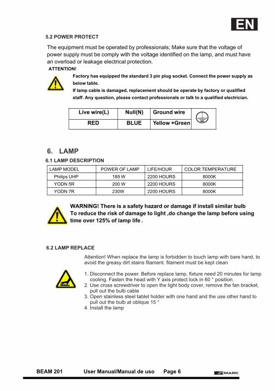
The equipment must be operated by professionals; Make sure that the voltage of
power supply must be comply with the voltage identified on the lamp, and must have
an overload or leakage electrical protection.ATTENTION!
Factory has equipped the standard 3 pin plug socket. Connect the power supply as
below table.
If lamp cable is damaged, replacement should be operate by factory or qualified
staff. Any question, please contact professionals or talk to a qualified electrician.
Live wire(L) Null(N) Ground wire
RED BLUE Yellow +Green
6. LAMP
LAMP MODEL POWER OF LAMP LIFE/HOUR COLOR TEMPERATURE
Philips UHP 189 W 2200 HOURS 8000K
YODN 5R 200 W 2200 HOURS 8000K
YODN 7R 230W 2200 HOURS 8000K
WARNING! There is a safety hazard or damage if install similar bulb
To reduce the risk of damage to light ,do change the lamp before using
time over 125% of lamp life .
Attention! When replace the lamp is forbidden to touch lamp with bare hand, to avoid the greasy dirt stains filament. filament must be kept clean
1. Disconnect the power. Before replace lamp, fixture need 20 minutes for lamp cooling. Fasten the head with Y axis protect lock in 60 ° position.2. Use cross screwdriver to open the light body cover, remove the fan bracket, pull out the bulb cable3. Open stainless steel tablet holder with one hand and the use other hand to pull out the bulb at oblique 15 °4. Install the lamp
6.2 LAMP REPLACE
6.1 LAMP DESCRIPTION
5.2 POWER PROTECT
BEAM 201 User Manual/Manual de uso Page 6
EN
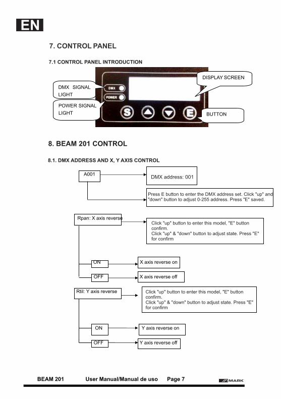
7. CONTROL PANEL
A001
Rpan: X axis reverse
ON X axis reverse on
OFF X axis reverse off
Rtil: Y axis reverse
ON Y axis reverse on
OFF Y axis reverse off
POWER SIGNAL
LIGHT
DMX SIGNAL
LIGHT
DISPLAY SCREEN
BUTTON
DMX address: 001
Press E button to enter the DMX address set. Click "up" and "down" button to adjust 0-255 address. Press "E" saved.
Click "up" button to enter this model, "E" button confirm. Click "up" & "down" button to adjust state. Press "E"for confirm
Click "up" button to enter this model, "E" button confirm. Click "up" & "down" button to adjust state. Press "E"for confirm
7.1 CONTROL PANEL INTRODUCTION
8.1. DMX ADDRESS AND X, Y AXIS CONTROL
8. BEAM 201 CONTROL
BEAM 201 User Manual/Manual de uso Page 7
EN
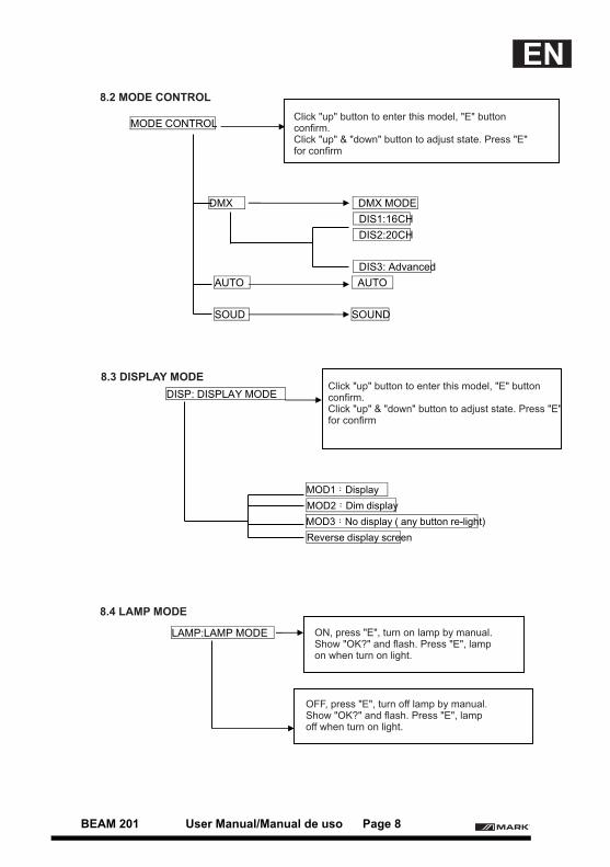
MODE CONTROL
DMX DMX MODE
DIS1:16CH
DIS2:20CH
DIS3: Advanced
AUTO AUTO
SOUD SOUND
DISP: DISPLAY MODE
MOD1:Display
MOD2:Dim display
MOD3:No display ( any button re-light)
Reverse display screen
LAMP:LAMP MODE
Click "up" button to enter this model, "E" button confirm. Click "up" & "down" button to adjust state. Press "E"for confirm
Click "up" button to enter this model, "E" button confirm. Click "up" & "down" button to adjust state. Press "E"for confirm
ON, press "E", turn on lamp by manual.Show "OK?" and flash. Press "E", lampon when turn on light.
OFF, press "E", turn off lamp by manual.Show "OK?" and flash. Press "E", lampoff when turn on light.
8.2 MODE CONTROL
8.3 DISPLAY MODE
8.4 LAMP MODE
BEAM 201 User Manual/Manual de uso Page 8
EN
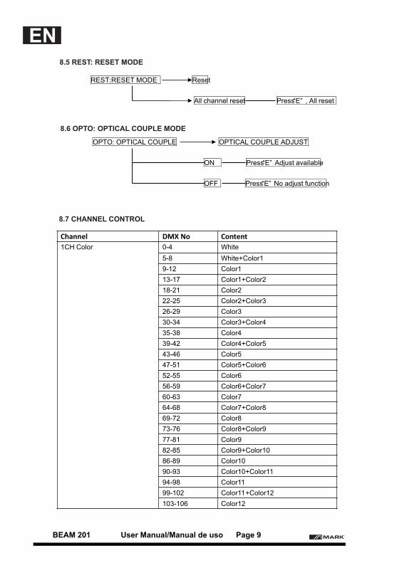
REST:RESET MODE Reset
All channel reset Press“E” , All reset
OPTO: OPTICAL COUPLE OPTICAL COUPLE ADJUST
ON Press“E” Adjust available
OFF Press“E” No adjust function
Channel DMX No Content
1CH Color 0-4 White
5-8 White+Color1
9-12 Color1
13-17 Color1+Color2
18-21 Color2
22-25 Color2+Color3
26-29 Color3
30-34 Color3+Color4
35-38 Color4
39-42 Color4+Color5
43-46 Color5
47-51 Color5+Color6
52-55 Color6
56-59 Color6+Color7
60-63 Color7
64-68 Color7+Color8
69-72 Color8
73-76 Color8+Color9
77-81 Color9
82-85 Color9+Color10
86-89 Color10
90-93 Color10+Color11
94-98 Color11
99-102 Color11+Color12
103-106 Color12
8.5 REST: RESET MODE
8.6 OPTO: OPTICAL COUPLE MODE
8.7 CHANNEL CONTROL
BEAM 201 User Manual/Manual de uso Page 9
EN
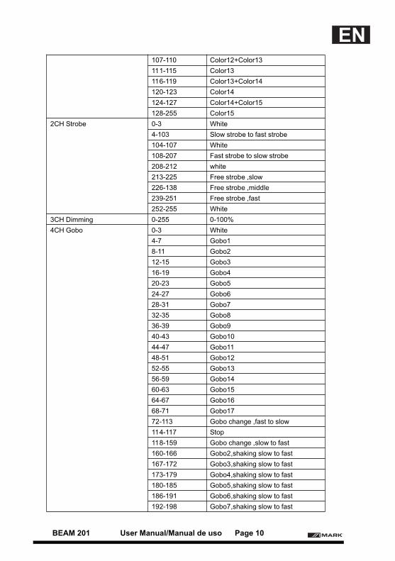
107-110 Color12+Color13
111-115 Color13
116-119 Color13+Color14
120-123 Color14
124-127 Color14+Color15
128-255 Color15
2CH Strobe 0-3 White
4-103 Slow strobe to fast strobe
104-107 White
108-207 Fast strobe to slow strobe
208-212 white
213-225 Free strobe ,slow
226-138 Free strobe ,middle
239-251 Free strobe ,fast
252-255 White
3CH Dimming 0-255 0-100%
4CH Gobo 0-3 White
4-7 Gobo1
8-11 Gobo2
12-15 Gobo3
16-19 Gobo4
20-23 Gobo5
24-27 Gobo6
28-31 Gobo7
32-35 Gobo8
36-39 Gobo9
40-43 Gobo10
44-47 Gobo11
48-51 Gobo12
52-55 Gobo13
56-59 Gobo14
60-63 Gobo15
64-67 Gobo16
68-71 Gobo17
72-113 Gobo change ,fast to slow
114-117 Stop
118-159 Gobo change ,slow to fast
160-166 Gobo2,shaking slow to fast
167-172 Gobo3,shaking slow to fast
173-179 Gobo4,shaking slow to fast
180-185 Gobo5,shaking slow to fast
186-191 Gobo6,shaking slow to fast
192-198 Gobo7,shaking slow to fast
BEAM 201 User Manual/Manual de uso Page 10
EN
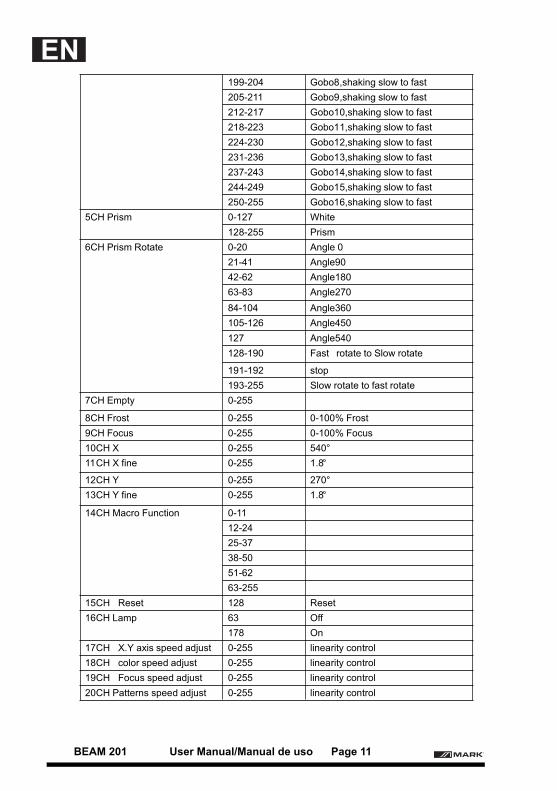
199-204 Gobo8,shaking slow to fast
205-211 Gobo9,shaking slow to fast
212-217 Gobo10,shaking slow to fast
218-223 Gobo11,shaking slow to fast
224-230 Gobo12,shaking slow to fast
231-236 Gobo13,shaking slow to fast
237-243 Gobo14,shaking slow to fast
244-249 Gobo15,shaking slow to fast
250-255 Gobo16,shaking slow to fast
5CH Prism 0-127 White
128-255 Prism
6CH Prism Rotate 0-20 Angle 0
21-41 Angle90
42-62 Angle180
63-83 Angle270
84-104 Angle360
105-126 Angle450
127 Angle540
128-190 Fast rotate to Slow rotate
191-192 stop
193-255 Slow rotate to fast rotate
7CH Empty 0-255
8CH Frost 0-255 0-100% Frost
9CH Focus 0-255 0-100% Focus
10CH X 0-255 540°
11CH X fine 0-255 1.8°
12CH Y 0-255 270°
13CH Y fine 0-255 1.8°
14CH Macro Function 0-11
12-24
25-37
38-50
51-62
63-255
15CH Reset 128 Reset
16CH Lamp 63 Off
178 On
17CH X.Y axis speed adjust 0-255 linearity control
18CH color speed adjust 0-255 linearity control
19CH Focus speed adjust 0-255 linearity control
20CH Patterns speed adjust 0-255 linearity control
BEAM 201 User Manual/Manual de uso Page 11
EN
DECLARACIONEl producto está bien empaquetado cuando envían de la fábrica. Todos los usuarios deben acatar estrictamente las advertencias e instrucciones que se indican en este manual, los daños y los resultados debido al mal uso y el descuido de este manual serán excluidos de la responsabilidad .
DESCRIPCION DEL PRODUCTOGracias por elegir BEAM 201, este modelo es una cabeza móvil que representa el último desarrollo de productos inteligentes y eficientes, gran combinación I + D, junto con la avanzada tecnología de iluminación con control electrónico avanzado y excelente diseño de fácil uso, cumple plenamente con las normas CE, aceptabdo la norma internacional DMX512 como modo de señal.
Esta cabeza móvil, usar un reflector cerámico de película luminiscente y un sistema de condensador, junto con componentes de alta calidad en lentes ópticas y la luz de salida uniforme y eficiente. BEAM 201, tienen 16/20 canales DMX512 estándar internacional. PAN scan: 540 ° Tilt scan: 270 ° (escaneo de precisión de 16 bits) Corrección electrónica, de matriz de puntos, cuatro teclas táctiles LCD+ Single-Key. La unidad puede colocarse invertida 180 º, la rueda de color combina el color blanco y14 colores. Rueda de gobos: 7 patrones circulares + efecto blanco por ocho prisma y la función de atomatización. dimmer mecánico 0-100%, luz estroboscópica, soporte mecánico y efecto estroboscópico variable, función estroboscópica macro. El sistema óptico del grupo de lentes con enfoque eléctrico y ángulo de haz entre 0 y 4º con función de protección ante sobrecalentamiento.
Las cabezas móviles son ampliamente utilizadas en televisión, discoteca, salas de baile, grandes actuaciones, etc.
1. INTRODUCCION AL PRODUCTO
Dimensiones:395(L)×287(W)×495(H)mmPeso neto:17.5KG
2. INFORMACION DE SEGURIDAD
Mensaje de advertencia de seguridadEste producto sólo es adecuado para el uso profesional, y no se aplica a la seguridad para otros fines.Después de recibir este dispositivo, por favor compruebe si el paquete tiene daños causados por el transporte.Si hay algún daño, no utilice este aparato, y por favor, póngase en contacto con el distribuidor o
1.1 DIMENSIONES Y PESO
BEAM 201 User Manual/Manual de uso Page 12
ES
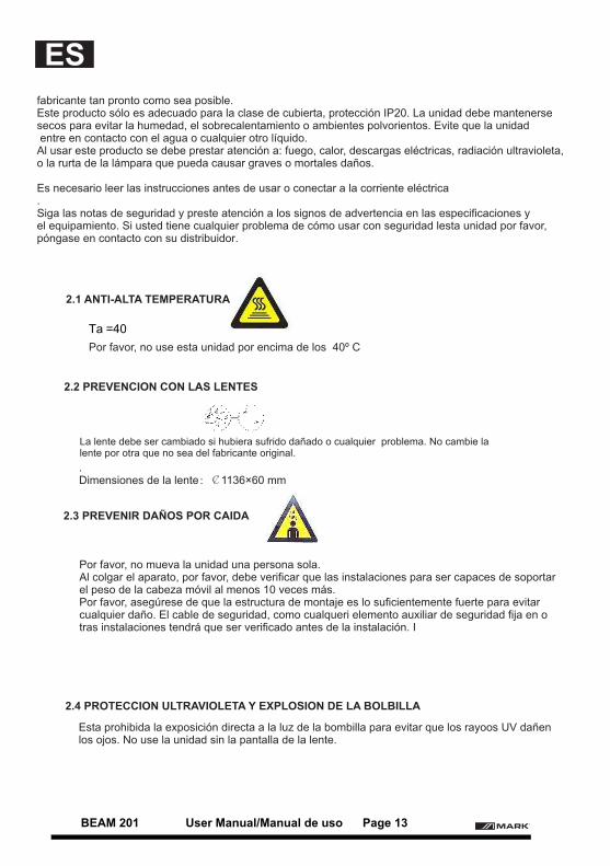
Ta =40
fabricante tan pronto como sea posible.Este producto sólo es adecuado para la clase de cubierta, protección IP20. La unidad debe mantenerse secos para evitar la humedad, el sobrecalentamiento o ambientes polvorientos. Evite que la unidad entre en contacto con el agua o cualquier otro líquido.Al usar este producto se debe prestar atención a: fuego, calor, descargas eléctricas, radiación ultravioleta, o la rurta de la lámpara que pueda causar graves o mortales daños.
Es necesario leer las instrucciones antes de usar o conectar a la corriente eléctrica.Siga las notas de seguridad y preste atención a los signos de advertencia en las especificaciones y el equipamiento. Si usted tiene cualquier problema de cómo usar con seguridad lesta unidad por favor, póngase en contacto con su distribuidor.
Por favor, no use esta unidad por encima de los 40º C
.Dimensiones de la lente:¢1136×60 mm
Por favor, no mueva la unidad una persona sola.Al colgar el aparato, por favor, debe verificar que las instalaciones para ser capaces de soportar el peso de la cabeza móvil al menos 10 veces más.Por favor, asegúrese de que la estructura de montaje es lo suficientemente fuerte para evitarcualquier daño. El cable de seguridad, como cualqueri elemento auxiliar de seguridad fija en otras instalaciones tendrá que ser verificado antes de la instalación. I
Esta prohibida la exposición directa a la luz de la bombilla para evitar que los rayoos UV dañen los ojos. No use la unidad sin la pantalla de la lente.
2.1 ANTI-ALTA TEMPERATURA
2.2 PREVENCION CON LAS LENTES
2.3 PREVENIR DAÑOS POR CAIDA
2.4 PROTECCION ULTRAVIOLETA Y EXPLOSION DE LA BOLBILLA
La lente debe ser cambiado si hubiera sufrido dañado o cualquier problema. No cambie lalente por otra que no sea del fabricante original.
BEAM 201 User Manual/Manual de uso Page 13
ES
3.
1
1
2
1
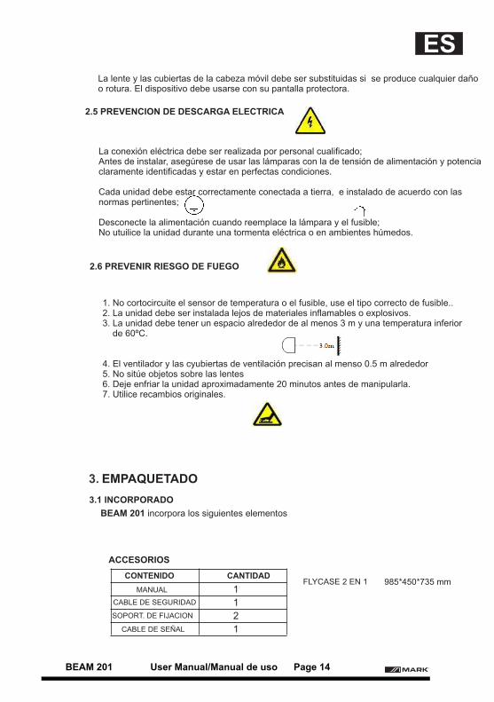
La lente y las cubiertas de la cabeza móvil debe ser substituidas si se produce cualquier daño o rotura. El dispositivo debe usarse con su pantalla protectora.
La conexión eléctrica debe ser realizada por personal cualificado;Antes de instalar, asegúrese de usar las lámparas con la de tensión de alimentación y potencia claramente identificadas y estar en perfectas condiciones.
Cada unidad debe estar correctamente conectada a tierra, e instalado de acuerdo con las normas pertinentes;
Desconecte la alimentación cuando reemplace la lámpara y el fusible;No utuilice la unidad durante una tormenta eléctrica o en ambientes húmedos.
1. No cortocircuite el sensor de temperatura o el fusible, use el tipo correcto de fusible..2. La unidad debe ser instalada lejos de materiales inflamables o explosivos.3. La unidad debe tener un espacio alrededor de al menos 3 m y una temperatura inferior de 60ºC.
4. El ventilador y las cyubiertas de ventilación precisan al menso 0.5 m alrededor5. No sitúe objetos sobre las lentes6. Deje enfriar la unidad aproximadamente 20 minutos antes de manipularla.7. Utilice recambios originales.
BEAM 201 incorpora los siguientes elementos
2.5 PREVENCION DE DESCARGA ELECTRICA
2.6 PREVENIR RIESGO DE FUEGO
3.1 INCORPORADO
EMPAQUETADO
ACCESORIOS
CONTENIDO CANTIDAD
MANUAL
CABLE DE SEGURIDAD
SOPORT. DE FIJACION
CABLE DE SEÑAL
985*450*735 mmFLYCASE 2 EN 1
BEAM 201 User Manual/Manual de uso Page 14
ES
Con el fin de proteger la unidad, hay una protección de bloqueo; Durante el transporte, el bloqueo se cierra para mantener el producto en estado de seguridad
Nota: Antes de desembalar comprobar si se ha producido daños debidos al transporte, si encuentra algún daño, por favor no utilice este elemento, y el contacto con el
distribuidor o fabricante tan pronto como sea posible.
1. Abra los gendarmes de seguridad del flycase para acceder a,la bolsa de plástico2. Saque la unidad cogiendo de las dos asas la base inferior.3. Antes de encenderlo, asegúrese de que ha desbloqueado el bloqueo de seguridad de los ejes X e Y.
BEAM 201 puede ser situado sobre un escenario o montado en una dirección arbritraria sobreun truss. Los dos soportes incorporados le permitirán fijarlo.
1. Antes de la instalación debe verificar que los soportes está en buen estado, y pueden soportar al menos 10 veces el peso del producto. Verificar que la instalación puede soportar al menos 10 veces el peso total de los equipos y accesorios.2. Fije el soporte en el agujero que se encuentra en la parte inferior de la unidad. Gire la palomilla 1/4 de vuelta y bloquee la unidad. Haga la misma operación con el otro soporte.3. El cable de seguridad debe permitirle soportar 10 veces el peso del equipo.
4. INSTALACION STANDARD
3.2 BLOQUEO DE SEGURIDAD DURANTE EL TRANPORTE
3.3 SOBRE EL FLYCASE
3.4 DESEMBALANDO
4.1 SOPORTES DE INSTALACION
4.2 FIJANDO LA UNIDAD
1. Antes de guardar la unidad, espere unos 20 minutos para que se enfríe.2. Antes de limpiar la unidad, asegúrese que el bloqueo de los ejes X e Y está bloqueado.3. Antes de meterlo en la bolsa de plástico, coja la unidad desde las asas y coloque la unidad en el flycase boca abajo.4. Después de empaquetar el producto, coloque los accesorios dentro del flycase y ciérrelo.5. El flycase sólo permite otro flycase encima. No apile mas de 2 unidades
BEAM 201 User Manual/Manual de uso Page 15
ES
5.
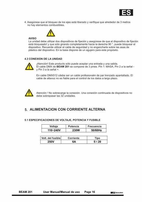
110~240V 230W 50/60Hz
250V 6A 5×20
4. Asegúrese que el bloqueo de los ejes está liberado y verifique que alrededor de 3 metros no hay elementos combustibles.
AVISOLa unidad debe utilizar dos dispositivos de fijación y asegúrese de que el dispositivo de fijación está bloqueado! y que sólo girando completamente hacia la derecha 90 °, puede bloquear el dispositivo. Recuerde utilizar el cable de seguridad y no engancharle sobre las asas deplástico del dispositivo. En la base dispone de un agujero para este propósito.
¡Atención! Este producto sólo puede aceptar una entrada y una salida.El cable DMX de BEAM 201 se compone de 3 pines. Pin 1: MASA, Pin 2 a la señal -y Pin 3 a la señal +.
En cable DMX512 cdebe ser un cable profesionalm de par trenzado apantallado. Elcable de altavoz no es fiable para el control de los datos a largo plazo.
Atención ! No sobrecarge la conexión. Una conexión continuada de dispositivos nodebe sobrepasar las 32 unidades.
4.3 CONEXION DE LA UNIDAD
5.1 ESPECIFICACIONES DE VOLTAJE, POTENCIA Y FUSIBLE
ALIMENTACION CON CORRIENTE ALTERNA
Voltaje Potencia Frecuencia
Volt. del fusible Corriente Tipo
BEAM 201 User Manual/Manual de uso Page 16
ES
6.
Philips UHP 189 W 2200 8000K
YODN 5R 200 W 2200 8000K
YODN 7R 230W 2200 8000K
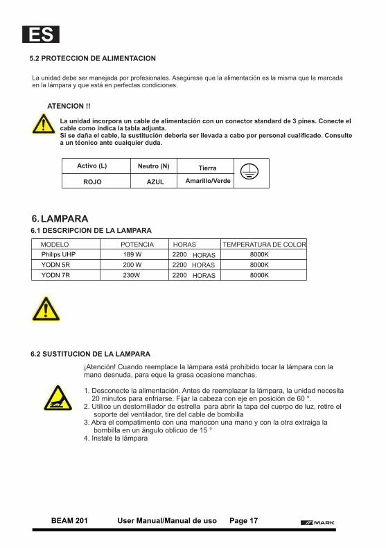
¡Atención! Cuando reemplace la lámpara está prohibido tocar la lámpara con la mano desnuda, para eque la grasa ocasione manchas.
1. Desconecte la alimentación. Antes de reemplazar la lámpara, la unidad necesita 20 minutos para enfriarse. Fijar la cabeza con eje en posición de 60 °.2. Utilice un destornillador de estrella para abrir la tapa del cuerpo de luz, retire el soporte del ventilador, tire del cable de bombilla3. Abra el compatimento con una manocon una mano y con la otra extraiga la
bombilla en un ángulo oblicuo de 15 °4. Instale la lámpara
6.2 SUSTITUCION DE LA LAMPARA
5.2 PROTECCION DE ALIMENTACION
La unidad debe ser manejada por profesionales. Asegúrese que la alimentación es la misma que la marcada en la lámpara y que está en perfectas condiciones.
ATENCION !!
La unidad incorpora un cable de alimentación con un conector standard de 3 pines. Conecte elcable como indica la tabla adjunta.Si se daña el cable, la sustitución debería ser llevada a cabo por personal cualificado. Consultea un técnico ante cualquier duda.
Activo (L) Neutro (N) Tierra
ROJO AZUL Amarillo/Verde
LAMPARA6.1 DESCRIPCION DE LA LAMPARA
MODELO POTENCIA HORAS TEMPERATURA DE COLOR
HORAS
HORAS
HORAS
BEAM 201 User Manual/Manual de uso Page 17
ES
7.
A001
ON
OFF
ON
OFF
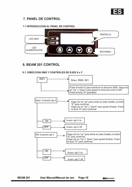
Direc. DMX: 001
Pulse el botón E para introducir la dirección DMX. Haga clic en "up" y "down" para ajustar la dirección entre 0-255 Pulse la tecla "E" guardado.
Haga clic en "up" para entrar en este modelo, el botón "E" para confirmar.Haga clic en "up" y "down" para ajustar Estado. Pulse la tecla "E" para confirmar
Haga clic en "up" para entrar en este modelo, el botón "E" para confirmar.Haga clic en "up" y "down" para ajustar Estado. Pulse la tecla "E" para confirmar
7.1 INTRODUCCION AL PANEL DE CONTROL
8.1. DIRECCION DMX Y CONTROLES DE EJES X e Y
8. BEAM 201 CONTROL
PANEL DE CONTROL
LED DMX
LED ALIMENTACION
PANTALLA
BOTONES
Rpan: inversión eje X
Rtil: inversión eje Y
Invers. eje X on
Invers. eje Y on
Invers. eje X off
Invers. eje Y off
BEAM 201 User Manual/Manual de uso Page 18
ES

MODE CONTROL
DMX DMX MODE
DIS1:16CH
DIS2:20CH
DIS3: Advanced
AUTO AUTO
SOUD SOUND
DISP: DISPLAY MODE
MOD1:Display
MOD2:Dim display
MOD3:
LAMP:LAMP MODE ON, pulsar la tecla "E", enciende la lámpara manual.Aparece "OK?" y parpadea. Pulse la tecla "E", la lámpara se enciende.
OFF, pulsar la tecla "E", apaga la lámpara manual.Aparece "OK?" y parpadea. Pulse la tecla "E", la lámpara se apaga.
8.2 MODO DE CONTROL
8.3 MODO DISPLAY
8.4 MODO LAMPARA
Haga clic en "up" para entrar en este modelo, el botón "E" para confirmar.Haga clic en "up" y "down" para ajustar Estado. Pulse la tecla "E" para confirmar
Haga clic en "up" para entrar en este modelo, el botón "E" para confirmar.Haga clic en "up" y "down" para ajustar Estado. Pulse la tecla "E" para confirmar
Sin display (cualquier tecla re-ilumina)
Invertir display
BEAM 201 User Manual/Manual de uso Page 19
ES
REST:RESET MODE Reset
OPTO:
ON
OFF
DMX No
1CH Color 0-4
5-8
9-12 Color1
13-17 Color1+Color2
18-21 Color2
22-25 Color2+Color3
26-29 Color3
30-34 Color3+Color4
35-38 Color4
39-42 Color4+Color5
43-46 Color5
47-51 Color5+Color6
52-55 Color6
56-59 Color6+Color7
60-63 Color7
64-68 Color7+Color8
69-72 Color8
73-76 Color8+Color9
77-81 Color9
82-85 Color9+Color10
86-89 Color10
90-93 Color10+Color11
94-98 Color11
99-102 Color11+Color12
103-106 Color12
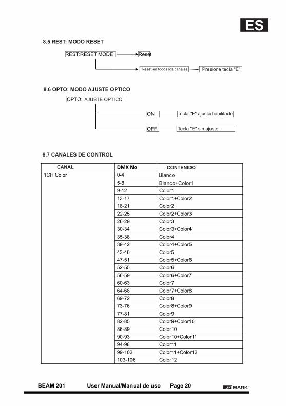
8.5 REST: MODO RESET
8.6 OPTO: MODO AJUSTE OPTICO
8.7 CANALES DE CONTROL
Reset en todos los canales Presione tecla "E"
AJUSTE OPTICO
Tecla "E" ajusta habilitado
Tecla "E" sin ajuste
CANAL CONTENIDO
Blanco
Blanco+Color1
BEAM 201 User Manual/Manual de uso Page 20
ES
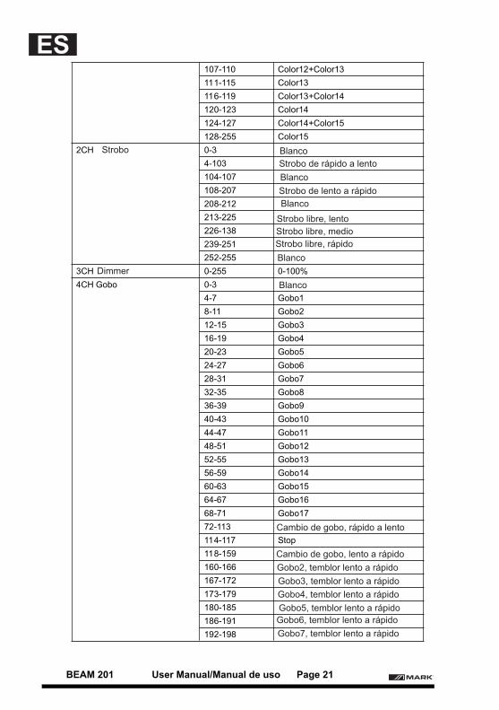
107-110 Color12+Color13
111-115 Color13
116-119 Color13+Color14
120-123 Color14
124-127 Color14+Color15
128-255 Color15
2CH 0-3
4-103
104-107
108-207
208-212
213-225
226-138
239-251
252-255
3CH 0-255 0-100%
4CH Gobo 0-3
4-7 Gobo1
8-11 Gobo2
12-15 Gobo3
16-19 Gobo4
20-23 Gobo5
24-27 Gobo6
28-31 Gobo7
32-35 Gobo8
36-39 Gobo9
40-43 Gobo10
44-47 Gobo11
48-51 Gobo12
52-55 Gobo13
56-59 Gobo14
60-63 Gobo15
64-67 Gobo16
68-71 Gobo17
72-113
114-117 Stop
118-159
160-166
167-172
173-179
180-185
186-191
192-198
Strobo
Dimmer
Blanco
Blanco
Blanco
Blanco
Blanco
Strobo libre, rápido
Strobo libre, medio
Strobo de lento a rápido
Strobo de rápido a lento
Strobo libre, lento
Cambio de gobo, lento a rápido
Cambio de gobo, rápido a lento
Gobo2, temblor lento a rápido
Gobo6, temblor lento a rápido
Gobo4, temblor lento a rápido
Gobo3, temblor lento a rápido
Gobo7, temblor lento a rápido
Gobo5, temblor lento a rápido
BEAM 201 User Manual/Manual de uso Page 21
ES
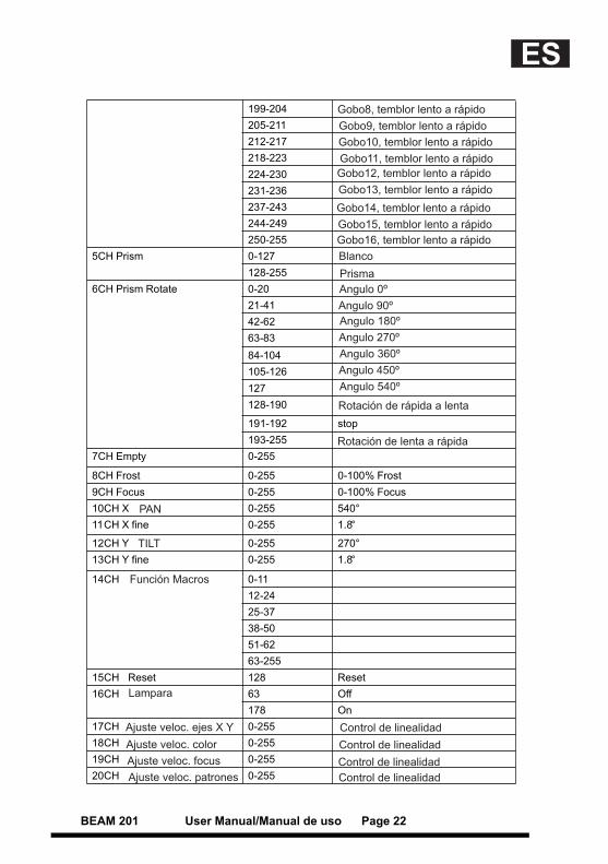
199-204
205-211
212-217
218-223
224-230
231-236
237-243
244-249
250-255
5CH Prism 0-127
128-255
6CH Prism Rotate 0-20
21-41
42-62
63-83
84-104
105-126
127
128-190
191-192 stop
193-255
7CH Empty 0-255
8CH Frost 0-255 0-100% Frost
9CH Focus 0-255 0-100% Focus
10CH X 0-255 540°
11CH X fine 0-255 1.8°
12CH Y 0-255 270°
13CH Y fine 0-255 1.8°
14CH 0-11
12-24
25-37
38-50
51-62
63-255
15CH Reset 128 Reset
16CH 63 Off
178 On
17CH 0-255
18CH 0-255
19CH 0-255
20CH 0-255
Gobo12, temblor lento a rápido
Gobo13, temblor lento a rápido
Gobo8, temblor lento a rápido
Gobo14, temblor lento a rápido
Gobo16, temblor lento a rápido
Gobo10, temblor lento a rápido
Gobo9, temblor lento a rápido
Gobo15, temblor lento a rápido
Gobo11, temblor lento a rápido
Blanco
Prisma
Angulo 0º
Angulo 180º
Angulo 360º
Angulo 540º
Angulo 90º
Angulo 270º
Angulo 450º
Rotación de rápida a lenta
Rotación de lenta a rápida
Control de linealidad
Control de linealidad
Control de linealidad
Control de linealidad
Lampara
Ajuste veloc. ejes X Y
Ajuste veloc. color
Ajuste veloc. focus
Ajuste veloc. patrones
Función Macros
PAN
TILT
BEAM 201 User Manual/Manual de uso Page 22
ES

EQUIPSON, S.A.Avda. El Saler, 14 - Pol. Ind. L´Alteró,46460 - Silla (Valencia) Spain
Tel. +34 96 121 63 01 Fax + 34 96 120 02 42
www.equipson.es [email protected]