Embed Size (px)
Citation preview

REV 3 April 2012
Bead Roller
Operating, Servicing, and Safety Instruction Manual
CAUTION: Read and Understand
These Operating, Servicing, and Safety Instructions, Before Using
This Machine.
1-800-467-2464 10 Cooperative Way Wright City, MO 63390
P.O. Box 110 Foristell, MO 63348 1-636-745-7757 Fax 1-636-745-2874 www.mittlerbros.com

- 2 -
Table of Contents
• Safety Pg.3
• Machine Set Up Pg.4-8
• Operation Pg.9
• Technical Diagrams Pg.10-14
• Bead Roller Accessories Pg.15
• Depth Stop Installation Instructions Pg.16

- 3 -
SAFETY The purpose of the safety section of this manual is to inform operators and
maintenance personnel of the precautions to be taken while operating or servicing the machine. The following are a few basic guidelines to follow, but as with any type of machinery
good judgment and a safe attitude should be applied at all times. 1 Always disconnect power, lock-out and tag-out machine per OSHA regulations before attempting
to service this machine. 2. Always wear safety glasses or other approved eye protection while operating or servicing the
machine. 3. Keep all body parts and any foreign objects away from moving parts. Do not reach into the
machine without first disconnecting all power sources. 4. Do not attempt to override any safety device on the machine. 5. Do not operate the machine if it has been damaged or is not operating properly. 6. Do not wear jewelry (watches, rings, necklaces, etc.), or loose fitting clothing while operating or
servicing the machine. 7. The machine should only be operated or serviced by properly trained, authorized personnel. 8. Replacement parts should have the same specification and operation as the original parts on the
machine. 9. All guards and covers must be in place before operating the machine. 10. Before starting the machine be sure it is set up properly. 11. Make sure the machine is properly grounded. 12. The machine and work area should be kept neat and clean. 13. Do not operate or service any machine while under the influence of drugs or alcohol. NOTE: THESE SAFETY RULES ARE FOR YOUR BENEFIT TO HELP PREVENT INJURY TO YOURSELF
AND/OR YOUR CO-WORKERS. REVIEW ALL SETUP AND OPERATING PROCEDURES, WHETHER COVERED OR NOT, IN THIS MANUAL TO HELP INSURE SAFE OPERATION OF THE MACHINE.
- 4 -
Assembly Instructions Industrial Variable Speed Motor on 36” Powered Bead Roller &
Standard To Industrial Motor Upgrade Kit
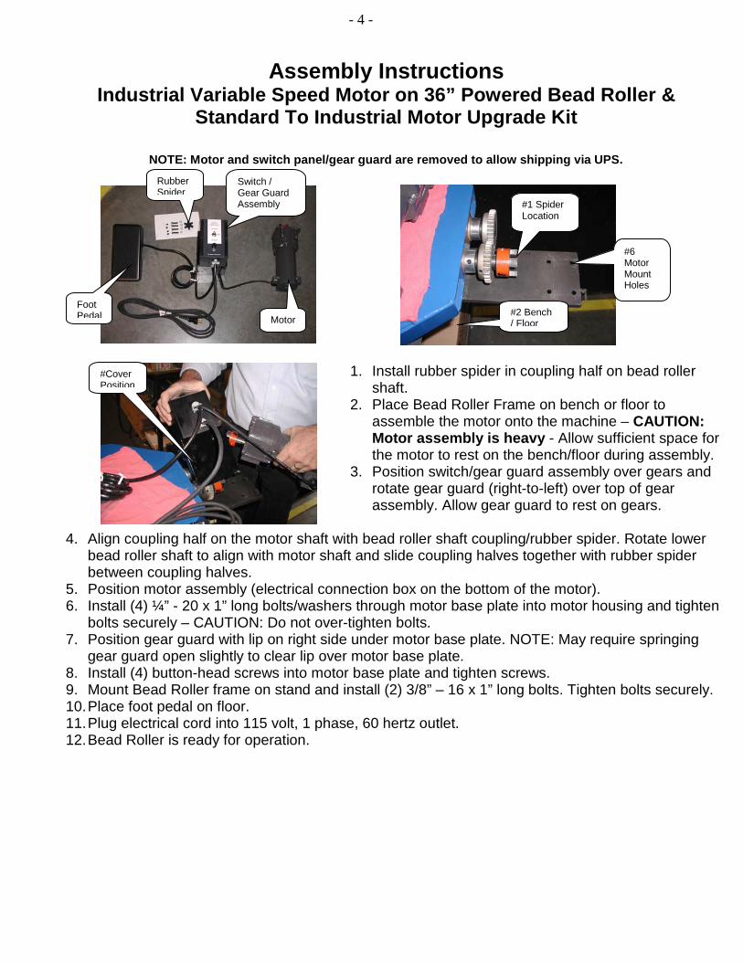
NOTE: Motor and switch panel/gear guard are removed to allow shipping via UPS.
1. Install rubber spider in coupling half on bead roller shaft.
2. Place Bead Roller Frame on bench or floor to assemble the motor onto the machine – CAUTION: Motor assembly is heavy - Allow sufficient space for the motor to rest on the bench/floor during assembly.
3. Position switch/gear guard assembly over gears and rotate gear guard (right-to-left) over top of gear assembly. Allow gear guard to rest on gears.
4. Align coupling half on the motor shaft with bead roller shaft coupling/rubber spider. Rotate lower
bead roller shaft to align with motor shaft and slide coupling halves together with rubber spider between coupling halves.
5. Position motor assembly (electrical connection box on the bottom of the motor). 6. Install (4) ¼” - 20 x 1” long bolts/washers through motor base plate into motor housing and tighten
bolts securely – CAUTION: Do not over-tighten bolts. 7. Position gear guard with lip on right side under motor base plate. NOTE: May require springing
gear guard open slightly to clear lip over motor base plate. 8. Install (4) button-head screws into motor base plate and tighten screws. 9. Mount Bead Roller frame on stand and install (2) 3/8” – 16 x 1” long bolts. Tighten bolts securely. 10. Place foot pedal on floor. 11. Plug electrical cord into 115 volt, 1 phase, 60 hertz outlet. 12. Bead Roller is ready for operation.
Rubber Spider
Switch / Gear Guard Assembly
Foot Pedal Motor
#1 Spider Location
#2 Bench / Floor
#Cover Position
#6 Motor Mount Holes

- 5 -
Motor & Gearbox Assembly For Models: 204-24NV & 204-36NV
Add upper gear box cover, secure with bolts
Bead Roller After Removed From
Shipping Package
Position motor assembly and install bolts / washer through motor base plate into motor
housing and tighten bolts securely CAUTION: Do not over-tighten bolts.
Install motor by aligning coupling half on the motor shaft with bead roller shaft coupling / rubber
spider. Rotate lower bead roller shaft to align with motor shaft and slide coupling halves together with rubber spider between coupling halves.
NOTE: Aluminum Spacers Between Motor &
Motor Plate 1
2
3
4

- 6 -
MACHINE SET UP
Floor Stand Assembly Instructions 1. Remove machine from packaging.
2. Assemble stand by installing 1/2-13 socket head cap screw (SHCS) through the bottom of the H-frame or caster base plate.
3. Install 2) 5/16-18 bolts through top of gusset. 4. Install rigid casters on back of base plate. 5. Install swivel casters on front of base plate. 6. Place machine on top of the bead roller stand and secure using (2) 3/8-16 x 1”
socket head cap screws.
Stationary Floor Stand Assembly #200-031
1/2 -13 SHCS thru Stand Bottom
5/16-18 Bolts thru Gusset Top
3/8-16 SHCS Bolts To Secure Stand To Bead Roller Frame From Side
Bead Roller Frame

- 7 -
FLOOR STAND with CASTERS
#200-150
1/2- 13 SHCS thru Stand Bottom
5/16- 18 SHCS Bolts from Top

- 8 -
MACHINE SET UP (cont.)
1. Remove shoulder bolt holding the aluminum handle to bottom of the bead depth adjuster. 2. Install aluminum handle on top of bead depth adjuster and secure using the shoulder bolt. 3. Remove the (2) 3/8-16 x 1” bolts and washers from the ends of the shafts. 4. Turn the bead depth adjuster counter-clockwise a 1 - 2 turns to allow clearance for rolls to slide
onto the shafts.
5. Place the bead rolls on the shafts with the MB logo stamp facing toward the machine. Either roll can be put on either shaft, but we usually recommend the male Bead Roll go on the top. Note: On 1-1/2” or 2” wide Bead Rolls, the socket head cap screw (SHCS) & washer MUST be installed in the Bead Roll recessed cavity.
6. Secure the rolls to the shafts with the SHCS & washers removed in step #7 and tighten both SHCS.
7. Place power cord and variable speed foot pedal on floor. 8. Plug into 115 volt, 1 phase, 60 hertz power outlet. 9. Machine is now ready for use.
SHCS Bolts and Washers to
Secure Rolls
MB Logo to Machine
Variable Speed Foot Pedal
115 Volt Plug
Bead Depth Adjuster Turn Counter-clockwise to Open
- 9 -
OPERATION
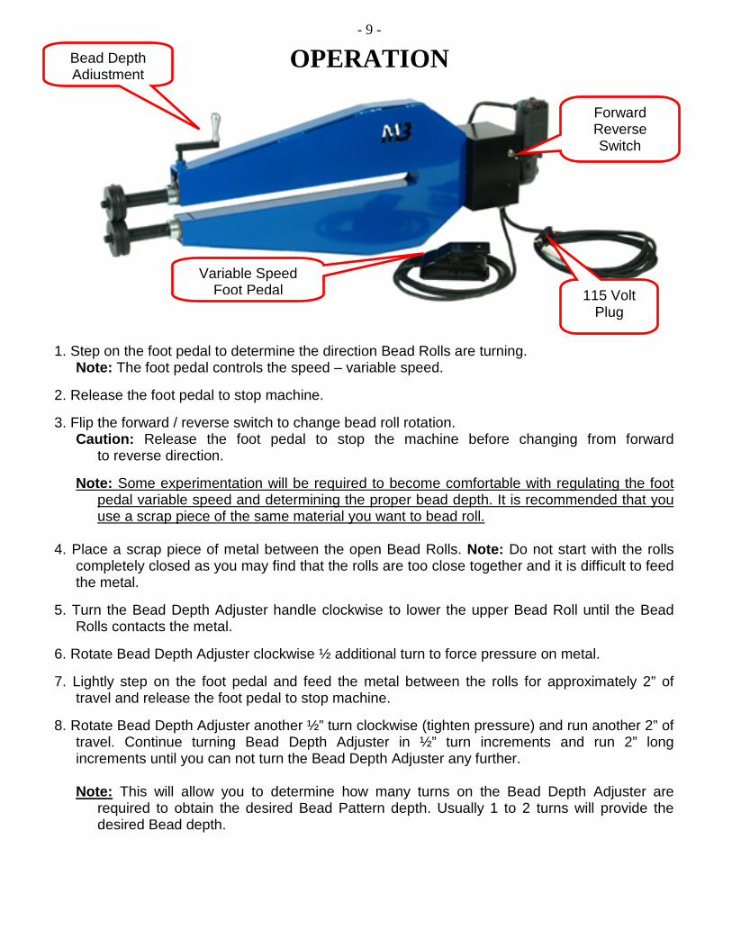
1. Step on the foot pedal to determine the direction Bead Rolls are turning. Note: The foot pedal controls the speed – variable speed.
2. Release the foot pedal to stop machine. 3. Flip the forward / reverse switch to change bead roll rotation.
Caution: Release the foot pedal to stop the machine before changing from forward to reverse direction.
Note: Some experimentation will be required to become comfortable with regulating the foot
pedal variable speed and determining the proper bead depth. It is recommended that you use a scrap piece of the same material you want to bead roll.
4. Place a scrap piece of metal between the open Bead Rolls. Note: Do not start with the rolls
completely closed as you may find that the rolls are too close together and it is difficult to feed the metal.
5. Turn the Bead Depth Adjuster handle clockwise to lower the upper Bead Roll until the Bead
Rolls contacts the metal. 6. Rotate Bead Depth Adjuster clockwise ½ additional turn to force pressure on metal. 7. Lightly step on the foot pedal and feed the metal between the rolls for approximately 2” of
travel and release the foot pedal to stop machine. 8. Rotate Bead Depth Adjuster another ½” turn clockwise (tighten pressure) and run another 2” of
travel. Continue turning Bead Depth Adjuster in ½” turn increments and run 2” long increments until you can not turn the Bead Depth Adjuster any further.
Note: This will allow you to determine how many turns on the Bead Depth Adjuster are
required to obtain the desired Bead Pattern depth. Usually 1 to 2 turns will provide the desired Bead depth.
115 Volt Plug
Variable Speed Foot Pedal
Forward Reverse Switch
Bead Depth Adjustment

- 10 -
PRICE
20
21
11
20
21
11
26
4
4
69
18
13
25
20
212
4
11
310
18
17
1516
19
28
30
24
27
20
12
3
10
5
7
4
11
2314
24" BEAD ROLLER PARTS LIST
Power Cord 16/3130200-520 Foot Pedal, Variable Speed129200-517 1/2" Romex Connector128200-507 Reversing Switch127200-514 Lock Screw226200-516 5/16" x 1 3/4" Handle Bolt325SBHCSCREW 10-32x3/8"224HX-SHCS 1/4"-20x3/4323FW 3/8"421HX-SHCS 3/8"-16x1"620200-048 Switch Box Cover1193/16" Key Stock118200-504 3/4" Coupling Half117200-503 1/2" Coupling Half116
PART NO.QTY.ITEM NO.
200-505 Spider115200-506 Motor114200-110 Aluminum Handle113200-013 Motor Mount Plate112200-502 Set Collar411
200-519 1/4" x 2" Roll Pin210200-023 T-Nut19200-026 Handle Mount18200-017 Adjustable Bearing Block17200-016 Adjustable Bearing Block16200-022U Upper Shaft15200-501 Flanged Bronze Bushing44200-024 Drive Gear23200-022L Lower Shaft12200-060 Frame11PART NO.QTY.ITEM NO.

- 11 -
PRICE
20
21
11
20
21
11
26
4
4
69
18
13
25
20
212
4
11
310
18
17
1516
19
28
30
24
27
20
12
3
10
5
7
4
11
2314
36" BEAD ROLLER PARTS LIST
Power Cord 16/3130200-520 Foot Pedal, Variable Speed129200-517 1/2" Romex Connector128200-507 Reversing Switch127200-514 Lock Screw226200-516 5/16" x 1 3/4" Handle Bolt325SBHCSCREW 10-32x3/8"224HX-SHCS 1/4"-20x3/4"323FW 0 3/8"421HX-SHCS 3/8"-16x1"620200-048 Switch Box Cover1193/16" Key Stock118200-504 3/4" Coupling Half117200-503 1/2" Coupling Half116
PART NO.QTY.ITEM NO.
200-505 Spider115200-506 Motor114200-110 Aluminum Handle113200-013 Motor Mount Plate112200-502 Set Collar411
200-519 1/4" x 2" Roll Pin210200-023 T-Nut19200-026 Handle Mount18200-017 Adjustable Bearing Block17200-016 Adjustable Bearing Block16200-061U Upper Shaft15200-501 Flanged Bronze Bushing44200-024 Drive Gear23200-061L Lower Shaft12200-070 Frame11PART NO.QTY.ITEM NO.

- 12 -
PRICE
20
21
11
20
21
11
26
4
4
69
18
13
25
20
212
4
11
310
18
17
1516
19
28
30
24
27
20
12
3
10
5
7
4
11
2314
42" BEAD ROLLER PARTS LIST
Power Cord 16/3130200-520 Foot Pedal, Variable Speed129200-517 1/2" Romex Connector128200-507 Reversing Switch127200-514 Lock Screw226200-516 5/16" x 1 3/4" Handle Bolt325SBHCSCREW 10-32x3/8"224HX-SHCS 1/4"-20x3/4"323FW 0 3/8"421HX-SHCS 3/8"-16x1"620200-048 Switch Box Cover1193/16" Key Stock118200-504 3/4" Coupling Half117200-503 1/2" Coupling Half116
PART NO.QTY.ITEM NO.
200-505 Spider115200-506 Motor114200-110 Aluminum Handle113200-013 Motor Mount Plate112200-502 Set Collar411
200-519 1/4" x 2" Roll Pin210200-023 T-Nut19200-026 Handle Mount18200-017 Adjustable Bearing Block17200-016 Adjustable Bearing Block16200-062U Upper Shaft15200-501 Flanged Bronze Bushing44200-024 Drive Gear23200-062L Lower Shaft12200-071 Frame11PART NO.QTY.ITEM NO.

- 13 -

- 14 -

- 15 -

- 16 -
#200-009 Depth Stop Installation Instructions
Purpose: Edge guide surface for flat or curved panels to assist in creating straight line bead profiles.
#200-14NV Rotary
#200-10NV) Rotary
#210-24, #200-36, #200-42
INSTRUCTIONS:
1. Insert aluminum “T” block into machine throat opening from the right hand side. 2. (Looking at machine from bead roll end with motor in back). 3. Install proper length bolt and flat strap from the left hand side.
a. NOTE: The aluminum “T” block can be located anywhere within the length of the machine throat to correspond with desired straight line position for creating a bead profile in metal.
4. Install round rod into the aluminum “T” block. NOTE: Round rod will telescope through “T” block to allow for fine-tuning desired location.
5. Tighten “T” handle to secure round rod and edge guide surfaces at desired location.
Requires a 3/8”x16-2 ¼” SHCS
Requires a 3/8”x16-1 ¾”” SHCS
Requires a 3/8”x16-1 ¾”” SHCS