Embed Size (px)
Citation preview
BE1-32R, BE1-32O/U
1
APPLICATIONPages 2 - 4
SPECIFICATIONSPages 4 - 8
EXTERNALCONNECTIONS
Pages 9 - 10
ORDERINGINFORMATIONPages 11 - 12
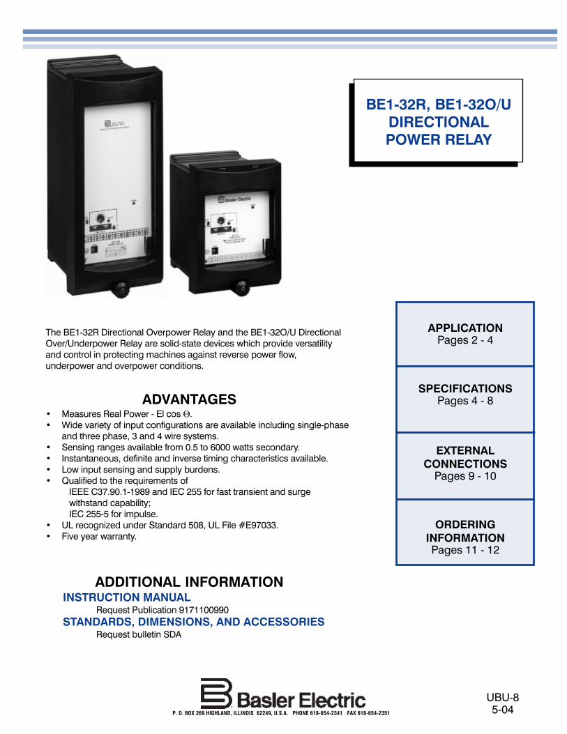
The BE1-32R Directional Overpower Relay and the BE1-32O/U DirectionalOver/Underpower Relay are solid-state devices which provide versatilityand control in protecting machines against reverse power flow,underpower and overpower conditions.
ADVANTAGES� Measures Real Power - El cos Θ.� Wide variety of input configurations are available including single-phase
and three phase, 3 and 4 wire systems.� Sensing ranges available from 0.5 to 6000 watts secondary.� Instantaneous, definite and inverse timing characteristics available.� Low input sensing and supply burdens.� Qualified to the requirements of
IEEE C37.90.1-1989 and IEC 255 for fast transient and surgewithstand capability;IEC 255-5 for impulse.
� UL recognized under Standard 508, UL File #E97033.� Five year warranty.
ADDITIONAL INFORMATIONINSTRUCTION MANUAL
Request Publication 9171100990STANDARDS, DIMENSIONS, AND ACCESSORIES
Request bulletin SDA
UBU-85-04P. O. BOX 269 HIGHLAND, ILLINOIS 62249, U.S.A. PHONE 618-654-2341 FAX 618-654-2351
BE1-32R, BE1-32O/UDIRECTIONALPOWER RELAY

2
BE1-32R, BE1-32O/U
APPLICATION
PURPOSE
The BE1-32R Directional Overpower Relay and the BE1-32 O/U, Directional Over/Underpower Relays sense realpower flow (El cos Θ). These relays are solid-statedevices designed for use in single-phase or three-phasesystems to provide equipment protection for overpowerand/or underpower or to be used for supervisory controlof circuits. Both relay configurations may be used tomonitor either forward or reverse power. In the followingapplication examples, single-phase connections areshown for simplicity.
APPLICATION EXAMPLES
The BE1-32 relays (R and O/U) are typically used inapplications where excessive power flow in the trippingdirection is indicative of undesirable situations. Typicalexamples are discussed below. Notice: This product isnot recommended for power factors below 0.10. ContactBasler Electric for recommended products.
Figure 1 - Power Relay Motoring Protection Figure 2 - Power Relay Start Control
EXAMPLE 1 - ANTI MOTORING
In this example, the power relay is used to protect theprime mover rather than the generator. When an acgenerator, operating in parallel with a power system,loses prime mover torque, it remains in synchronismwith the system and continues to run as a synchronous
motor drawing sufficient power from the system to drivethe prime mover. Sustained motoring can cause severedamage to the prime mover. The Directional PowerRelay, with its wide sensitivity range, can detect levels ofreverse real power flow as low as 0.5 Watts secondaryand provide an alarm or trip the unit off line (See Figure1). In this example, single phase sensing is usuallyconsidered sufficient, since motoring is a balancedcondition.
EXAMPLE 2 - COGENERATOR CONTROL
Given that a co-generation system has automaticengine controls, auto synchronizer, and automatic kWand kVar controls, the system will virtually operate byitself. The only functions not readily apparent are thestart/stop signals to the generators. Two system con-figurations using a Power Relay may be utilized togenerate contact closures for start and/or stop signals.
The first configuration (Figure 2) shows a power relayconnected to the utility to sense kW. The pickup point ofthe relay is set at the maximum desired utility powerlevel. If the power relay contact closes, the generatorwill be started and automatically paralleled with theutility system. A time delay of 15 seconds or more isgenerally included in the �start� circuit to ignoretransient overload conditions.
TRIP52
TRIP
PIN
G D
IRE
CTI
ON
GENERATOR
BE1-32RWITH
E1TIMING
52
52
GENERATOR
BE1-32R WITHE1 TIMING
STARTSIGNAL
ENGINECONTROL
UTILITY
LOAD

BE1-32R, BE1-32O/U
3
APPLICATION, continued
When the generator is paralleled and loaded, the kWsignal will decrease by the amount of load the generatoraccepted. An underpower relay can measure utilitypower and generate a �stop� signal when utility powerdecreased below a selected level. A definite time delaywill generally be provided for the �stop� signal of oneminute or more. The Basler Model BE1-32 O/U PowerRelay incorporates both over and under power sensingin one relay, which makes it ideal for this application.
In the second configuration (Figure 3) the �start� signal isgenerated as in that of Figure 2. The setpoint of the startsignal should be above the import power setting. The�stop� signal will require an underpower relay on thegenerator output. This system is illustrated in Figure 3.
EXAMPLE 3 - GENERATOR OVERLOAD
Refer to Figure 3. Whenever excessive load has beenconnected to a generating system, the Power Relay willinitiate the corrective action by energizing an alarm toalert the station operator or will initiate an automaticsequence to either shed non-critical load or start andparallel an in-house generator to assume the excessload.
EXAMPLE 4 - DISTRIBUTION SYSTEM OVERLOAD
Another typical use, addressing excessive load, con-cerns distribution protection, see Figure 4. A high-voltage bus supplies two transformers. T1 and T2together can supply all connected load. However, neitherT1 or T2 is capable of supplying the total load. Toprovide adequate protection for the distribution system,the overpower function is used to sense overloadconditions on each transformer and the underpowerfunction is used to sense power flowing through thetransformers in an undesired direction.
Figure 3 - Power Relay Start/Stop Control
EXAMPLE 5 - REACTIVE POWER (VARs)DETECTION
This example deals with the Directional Power Relay�sability to measure real or reactive power.
Real power (watts) is supplied to the generator by theprime mover, and reactive power (vars) is supplied tothe field by the exciter. When field excitation is signifi-cantly reduced and the connected system can providesufficient reactive power to maintain the generator�sterminal voltage, reactive power will flow into themachine and cause it to operate as an inductiongenerator with essentially the same kW output. Thissituation causes problems; first, the additional reactiveloading of the faulty generator must be redistributed toother synchronous generators on the system. Secondly,a synchronous generator is not designed to function asan induction generator. Excessive heating occurs in thedamper (Amortisseur) windings, slot wedges, and in thesurface iron of the rotor due to slip frequency currentflow which results when a synchronous generator isoperated as an induction generator. The DirectionalPower Relay can be applied to respond to this reactivepower flow.
The Basler BE1-32 Directional Power Relay is designedto respond to true power as defined by the equation:
P = El cos Θ
where: P = real power (watts)E = effective emf or system voltageI = effective currentΘ = the phase angle between E and I
Figure 4 - Distribution Protection
GENERATOR1
52
LOAD
UTILITY
GEN 2OVERPOWER
STARTSIGNAL
GEN 1UNDERPOWERSTOP SIGNAL
BE1-32 O/UWITH
E1 TIMING
BE1-32R WITHE1 TIMING
52
STARTSIGNAL
ENGINECONTROL
HIGH VOLTAGE BUS
LOW VOLTAGE BUS
OVER-POWER
REVERSEPOWER
32O/U
32O/U
T1 T2
TRIP
PIN
G D
IRE
CTI
ON

4
BE1-32R, BE1-32O/U
APPLICATION, continued
Figure 5 - VARs Measuring
inability of the excitation system to supply adequatereactive power.
With the many options and combinations of optionsavailable, the Basler Electric Directional Power Relayscan be adapted to multitude of systems and situationsto provide the utmost in overpower and underpowerprotection of system equipment.
INPUTS
Current SensingSystem current transformers (CTs) with nominal 5 Asecondaries supply the Directional Power Relay�s inputtransformers with one, two or three phase currents.If sensing input range 1, 4 or 7 is selected, the inputtransformers are capable of 7 A continuous current,10 A for 1 minute and 140 A for 1 second.
However, reactive power is defined by the equation:
Q = El sin Θ
Since the sine of Q equals the cosine of (Q - 90°) therelay can be connected to measure only reactive powerby adding 90° in the connection of the PTs as shown inFigure 5. The relay is now capable of detecting the
FUNCTIONAL DESCRIPTION
The specifications on these pages define the manyfeatures and options that can be combined to exactlysatisfy a specific application requirement. The blockdiagram, Figure 6, illustrates how the various standardfeatures, as well as the options, function together.
SPECIFICATIONS
TRIPPING DIRECTION
TRUE POWER(WATTS)MONITORING
REACTIVE POWER(VARS)MONITORING
TRIPPING DIRECTION
A A
B B
C C
8 89 96 65 5
BE1-32 MODIFIEDTYPE "A" SENSING
BE1-32 MODIFIEDTYPE "A" SENSING
Figure 6 - Functional Block Diagram

BE1-32R, BE1-32O/U
5
SPECIFICATIONS, continued
If sensing input range 2, 3, 5, 6, 8 or 9 is selected, theinput transformers are capable of 10 A continuouscurrent, 15 A for 1 minute and 200 A for 1 second.
Sensing input ranges 1, 4, and 7 have notable burdenwhen the relay is set at maximum sensitivity. Refer tothe Current Sensing Burden table in the BE1-32R,BE1-32O/U Instruction Manual, Section 1, Specifica-tions, for the details.
Voltage SensingSystem potential transformers (PTs) with 120 or 240Vsecondaries supply the Directional Power Relay�s inputtransformers with single or three-phase voltages. Thevoltage sensing inputs are nominally rated at 100 or220V (50 Hz) and 120 or 240V (60 Hz) with a maximumburden of 1 VA per input (2 terminals) over the fre-quency range of 45 to 65 Hz. Maximum continuousvoltage is limited to 150% nominal.
SENSING INPUT TYPESThere are 6 sensing input types as defined by the StyleChart (page 12). The Directional Power Relay�s inputcircuitry receives voltage and current signals fromsystem PTs and CTs. The CT signal is adjusted in levelby a front panel range switch before it is applied to thekW transducer circuitry. Several input circuit configura-tions are available, the selection of which is determinedby the specific application. The following paragraphsprovide a brief description of each input sensing typeand their calibration
Type A Sensing: Single-Phase (Figure 7). The type Asensing configuration monitors line-to-neutral voltageand a single phase current of a three-phase, four-wirecircuit and calculates the power flowing in the trippingdirection. Relays with this sensing type are calibrated insingle-phase watts.
Type B (60 Hz) or Type V (50 Hz) Sensing: Single-Phase(Figure 8) with 30° phase shift. This sensing configurationmonitors a line-to-line voltage and a single phase currentof a three-phase, three-wire circuit and calculates thepower flowing in the tripping direction. Since the inputvoltage leads the input current by 30° (assuming unitypower factor) a 30° lagging phase shift network is de-signed into the voltage input circuit. Relays with thissensing type are calibrated in single-phase watts. Note:Type B or V configurations are phase rotation sensitive.
Type C Sensing: Three-phase Scott Tee (Figure 9). Thetype C sensing configuration monitors three line-to-linevoltages and a single phase current of a three-phase,three-wire circuit and calculates the power flowing in thetripping direction. The relay measures actual power evenif the system voltages are not balanced. Relays with thissensing type are calibrated in three-phase watts.
Figure 7 - Single Phase, Type A Sensing
Figure 9 - Three Phase, Type C Sensing
Figure 8 - Single Phase, Type B or V Sensing
TRIPPING DIRECTION
GENERATOR
P= E (B-N) IB COSθ
9 8 5 6
BE1-32TYPE "A" SENSING
CALIBRATION: SINGLE PHASE WATTS
A
B
IB
C
N
EB-N
θ
P= E (B-C) IB COSθ (∅ - 30°)
3
TRIPPING DIRECTION
GENERATOR
9 8 5 6
CALIBRATION: SINGLE PHASE WATTS
A
B
IB
C
EB-C
θ
BE1-32TYPE "B" OR "V" SENSING

6
BE1-32R, BE1-32O/U
SPECIFICATIONS, continued
Type D Sensing: Three-Phase (Figure 10). The type Dsensing configuration monitors three line-to-neutralvoltages and three phase currents of a three-phase, four-wire circuit and calculates the power flowing in thetripping direction. Relays with this sensing type arecalibrated in three-phase watts.
Type E Sensing: Three-Phase (Figure 11). The type Esensing configuration monitors three line-to-line voltagesand two of the phase currents of a three-phase, three-wire circuit and calculates the power flowing in thetripping direction. The power equation assumes thatconditions are balanced. Relays with this sensing typeare calibrated in three-phase watts. Note: Type E con-figurations are phase rotation sensitive.
Power SupplyOne of five power supply boxes may be selected toprovide internal operating power. They are described inTable 1.
POWER RANGE PICKUP
Overpower pickup of the relay is adjustable by means ofa front panel 10 position rotary TAP select switch used inconjunction with the front panel HIGH/LOW switch overthe defined ranges listed in Table 2. Underpower pickupis continuously adjustable from 10 to 95% of the selectedoverpower tap. Pickup accuracy is ±2% (or ±0.05 wattsone phase; ±0.15 watts 3 phase) of the front panel settingfor unity power factor. Pickup accuracy is ±5% of the frontpanel setting for all other power factors (0.5<pf<1.0). Therange of voltage for proper operation is 40 to 150 percentof the nominal value.
When the calculated value for power exceeds the over-power pickup setting or falls below the underpowerpickup setting and is in the tripping direction, the appro-priate LED is illuminated and timing is initiated. Oneindicating LED is provided for each measuring functionwithin the relay.
KW TRANSDUCER
The kW Transducer samples the current and voltage ofeach phase on a continuous basis. The resulting signalsrepresenting current and voltage are multiplied and in-tegrated to develop a dc voltage level that is representa-tive of true kW.
COMPARATOR CIRCUITS
The dc output of the kW Transducer is then compared tofront panel settings for underpower and/or overpower.When the reference level of the comparator (or compara-tors if applicable) is crossed, the output of the comparatoris used to either energize the appropriate output (ifinstantaneous timing has been specified) or to initiate thetiming circuits (definite, or inverse).
TIMING
Time delay is defined as the elapsed time between theapplication of the condition to the input terminals of therelay and the transition of the output contacts.
Table 1 - Wide Range Power Supply -Voltage Ranges
TRIPPING DIRECTION
GENERATOR
BE1-32TYPE "D" SENSING
CALIBRATION: THREE PHASE WATTS
5 6 7 16
N
C
B
A
812 1415 13 9
IA
IA
IA
IC
IA
IB
EA-N
EA-N
EA-N
EA-N
EB-N
θ
θ
θ
θ
θθ3 =
θ2 =
θ1 =θ
θ
P= 3E L-N IL COSθ
P= EANIA COSθ1 + EBNIB COSθ2 + ECNIC COSθ3
EC-N
IF BALANCED:
WHERE:
IF UNBALANCED:
Figure 10 - Three Phase, Type D Sensing
Figure 11 - Three Phase, Type E Sensing
P3= EABIA COS∅1 + ECBIC COS∅2
IF BALANCED:
WHERE:
IF UNBALANCED:
TRIPPING DIRECTION
GENERATOR
BE1-32TYPE "E" SENSING
CALIBRATION: THREE PHASE WATTS
A
B
C
9 13 12 8 5 6 7
IC
EAB
IAIA
ECB
∅2
∅1
P= 3 EL-L IA COSθ
Power SupplyStyle Chart Identifiers
Nominal Voltage Voltage Range Burden
Mid Range P48/125 Vdc;
120 Vac 24 to 150 Vdc; 90 to 132 Vac
5.2 W; 15.1 VA
Low Range * R 24 Vdc 12 to 32 Vdc 5.1 W
High Range T125/250 Vdc; 120/240 Vac
62 to 280 Vdc; 90 to 270 Vac
5.2 W; 14.0 VA
*The Type R power supply may require 14 Vdc to begin operation. Once operating, the voltage may be reduced to 12 Vdc.

BE1-32R, BE1-32O/U
7
SPECIFICATIONS, continued
Each model, BE1-32R or BE1-32 O/U is capable ofinstantaneous trip, definite time delay trip, or an inversetime delayed trip as defined and selected by the StyleChart.
Instantaneous response time of the relay is within 80 ms(60 Hz) or 100 ms (50 Hz) for a real power magnitude of2 times the setting.
The definite time delay is adjustable over the ranges of0.1 to 9.9 seconds and 01 to 99 seconds. Selection ofthe ranges is accomplished by a front-panel multiplierswitch which selects either 0.1 or 1.0 as a multiplier ofthe front panel Time Dial thumbwheel switch. (A TimeDial setting of 00 enables instantaneous operation.)Definite timing accuracy is ±5% of the setting or 50 ms,whichever is greater.
Inverse time delayed trip is available for the overpowerfunction only. The inverse time delay curve is adjustablefrom 01 to 99 by means of a front-panel thumbwheelswitch. Incrementing the thumbwheel switch moves theinverse curve along the vertical axis. (See Figure 12 forInverse Time Characteristics.) A Time Dial setting of 00enables instantaneous operation. Inverse time isaccurate to within ±5% of the published curve or50 ms, whichever is greater.
POWER SUPPLY STATUS OUTPUT (OPTIONAL)
The power supply status output relay is energized andits NC output contact is opened when power is appliedto the relay. Normal internal relay operating voltagemaintains the power supply status output relay continu-ously energized with its output contact open. If thepower supply output voltage falls below the require-ments of proper operation, the power supply outputrelay is deenergized, closing the NC output contact.
Table 2 - Power Range Pickup Settings
SensingInputType
2.00.5205
100256.01.56015
300754.01.04010
20050
12.03.012030
600150
4.01.04010
20050
12.03.012030
6001508.02.08020
40010024.06.024060
1200300
6.01.56015
30075
18.04.518045
90022512.03.012030
60015036.09.036090
1800450
8.02.08020
40010024.06.024060
120030016.04.016040
80020048.012.0480120
2400600
10.02.510025
50012530.07.530075
150037520.05.020050
100025060.015.0600150
3000750
12.03.012030
60015036.09.036090
180045024.06.024060
120030072.018.0720180
3600900
14.03.514035
70017542.010.5420105
210052528.07.028070
140035084.021.0840210
42001050
16.04.016040
80020048.012.0480120
240060032.08.032080
160040096.024.0960240
48001200
18.04.518045
90022554.013.5540135
270067536.09.036090
1800450
108.027.01080270
54001350
20.05.020050
100025060.015.0600150
300075040.010.0400100
2000500
120.030.01200300
60001500
NominalVolts Range
Switch Positions (in Watts)
A
1 Hi
Lo
Hi
Lo
Hi
Lo
Hi
Lo
Hi
Lo
Hi
Lo
Hi
Lo
Hi
Lo
Hi
Lo
Hi
Lo
Hi
Lo
Hi
Lo
1
4,7
4,7
2
2
5,8
5,8
3
3
6,9
6,9
120
A, B,orV
1∅
A, B,orV
1∅
C, D,orE
3∅
C, D,orE
3∅
120
208or
240
208or
240
B C D E F G H J K

8
BE1-32R, BE1-32O/U
SPECIFICATIONS, continued
TARGETS
Magnetically latched, manually reset target indicators areoptionally available to indicate that a trip output hasenergized. Either internally operated or current operatedtarget may be specified. Current operated targets require0.2 A in the output trip circuit to actuate, and trip currentmust not exceed 30 A for 0.2 seconds, 7 A for 2 minutes,and 3 A continuous. Current operated targets may beselected only when normally open (NO) output contactshave been specified.
PUSH-TO-ENERGIZE-OUTPUT PUSHBUTTONS
Applying a thin non-conducting rod through a hole in thefront panel energizes each output relay for testing theexternal trip circuits.
SURGE WITHSTAND CAPABILITY
Qualified to IEEE C37.90.1-1989 Surge Withstand Capa-bility Test and IEC 255.
FAST TRANSIENT
Qualified to IEEE C37.90.1-1989 Fast Transient Test.
IMPULSE TEST
Qualified to IEC 255-5.
MECHANICAL
Operating Temperature-40°C(-40°F) to +70°C(+158°F).
Storage Temperature-65°C(-85°F) to +100°C(+212°F).
WeightM1 - 18.5 pounds max.S1 - 13.5 pounds max.
ShockIn standard tests, the relay has withstood 15g in each ofthree mutually perpendicular axes without structuraldamage or degradation of performance.
VibrationIn standard tests, the relay has withstood 2g in each ofthree mutually perpendicular axes swept over the range of10 to 500 Hz for a total of six sweeps, 15 minutes eachsweep, without structural damage or degradation ofperformance.
OUTPUTS
Output contacts are rated as follows:
Resistive
120/240 Vac - make 30 A for 0.2 seconds, carry 7 A continuously, break 7 A.
250 Vdc - make and carry 30 A for 0.2 seconds, carry 7 A continuously, break 0.3 A.
500 Vdc - make and carry 15 A for 0.2 seconds, carry 7 A continuously, break 0.1 A.
Inductive
120/240 Vac, 125 Vdc, 250 Vdc - break 0.3 A(L/R = 0.04).
Figure 12 - Overpower Inverse Characteristics
.01
.10
1
10
100
0 1 2 3 4
MULTIPLE OF TAP VALUE
TIM
ED
EL
AY
(SE
CO
ND
S)
5 6 7 8 9 10
99
80
60
40
30
20
10
07
05
03
02
99

BE1-32R, BE1-32O/U
9
CONNECTIONS
Figure 13 - Sensing Connections(Continued next page)
52
BE1-32
A
B
C
N
5
6
8
9
TYPE A SENSING
GENERATOR
TRIP
PIN
G D
IRE
CTI
ON
52
BE1-32
A
B
C
5
6
8
9
TYPE B or V SENSING
GENERATOR
TRIP
PIN
G D
IRE
CTI
ON

10
BE1-32R, BE1-32O/U
CONNECTIONS(continued)
Figure 14 - Control Circuits
52
TRIP
PIN
G D
IRE
CTI
ON
BE1-32
GENERATOR
TYPE D SENSING
6
7
16
8
9
14
15
12
13
A
B
C
N
552
TRIP
PIN
G D
IRE
CTI
ON
BE1-32
GENERATOR
TYPE E SENSING WITH ABC ROTATION
6
7
8
9
12
13
5
A
B
C
52
TRIP
PIN
G D
IRE
CTI
ON
BE1-32
GENERATOR
TYPE E SENSING WITH ACB ROTATION
6
7
8
9
12
13
5
A
B
C
ROLL B AND C PHASES FORCHANGING ABC TO ACB ROTATION.
Figure 13 (continued) - Sensing Connections

BE1-32R, BE1-32O/U
11
ORDERINGMODEL NUMBER
BE1-32R Directional Power Relay and BE1-32 O/UDirectional Over/Underpower Relay.
STYLE NUMBER
The style number appears on the front panel, drawoutcradle, and inside the case assembly. This style numberis an alphanumeric combination of characters identify-ing the features included in a particular unit. Thesample style number below illustrates the manner inwhich the various features are designated. The StyleNumber Identification Chart (page 12) defines each ofthe options and characteristics available for this device.
SAMPLE STYLE NUMBER A1EA1PA0N2F
The style number above describes a BE1-32R Direc-tional Power Relay having the following features.
Sensing Input Type (A) Single-phase current andL-N voltage sensing
HOW TO ORDER:
Designate the model number followed by the completeStyle Number.
Complete the Style Number by selecting one featurefrom each column of the Style Number IdentificationChart and entering its designation letter or number intothe appropriate square. (Two squares are used toindicate time delay characteristics.) All squares must becompleted.
Sensing Input Range (1) 120 Vac, 0.5-20W
Output (E) One Output relay withnormally open contacts
Timing (A1) Instantaneous timing
Power Supply (P) 125 Vdc/120 Vac inputpower supply
Target (A) One internally operated target
Option 1 (0) None
Option 2 (N) None
Option 3 (2) One auxiliary output relaywith normally closed contacts
Option 4 (F) Semi-flush mounting
NOTE: The description of a complete relay mustinclude both the model number and the style number.
STANDARD ACCESSORIES:
The following accessories are available for the BE1-32Ror BE1-32 O/U Directional Power Relays.
Test PlugTo allow testing of the relay without removing systemwiring, order two test plugs, Basler Electric part number10095.
Extender BoardThe extender board permits troubleshooting of theprinted circuit boards outside of the relay cradle. OrderBasler Electric part number 9165500100.

12
BE1-32R, BE1-32O/U
STYLE NUMBER IDENTIFICATION CHART
Route 143, Box 269, Highland, Illinois U.S.A. 62249Tel +1 618.654.2341 Fax +1 618.654.2351
e-mail: [email protected]
328 North Zhongshan Road, Wujiang Economic Development ZoneSuzhou, Jiangsu Province, PRC 215200
Tel +86(0)512 6346 1730 Fax +86(0)512 6346 1760e-mail: [email protected]
®Basle
r
ISO
Regis teredQuality
System
Highland, IL: ISO 9001Wasselonne, France: ISO 9001
Taylor, TX: ISO 9001
www.basler.com
P.A.E. Les Pins, 67319 Wasselonne Cedex FRANCETel +33 3.88.87.1010 Fax +33 3.88.87.0808
e-mail: [email protected]