Embed Size (px)
Citation preview
Power Electronics
Jivnsai Didatek, 09, Savarkar Nagar, Pimprala, Jalgaon, 425001, Maharashtra, India
Email: [email protected] , [email protected], Website: www.jivnsai.com
STUDY OF SCR/MOSFET/IGBT/TRIAC/DIAC CHARACTERISTICS
The set up comes in two parts with provision for high voltage variable power supply (0 to 500
volts), 0 to 10 volts with voltmeter and provision for gate current measurement, anode
current measurement in the range of 0 to 20 mA & 0to 500mA respectively. The part (A)
houses variable power supply and part B provides facility to connect various SCR or MOSFET,
Diac ,Triac, IGBT along with load. Various characteristics of the device with measurement of
latching current, holding current for SCR can be performed.
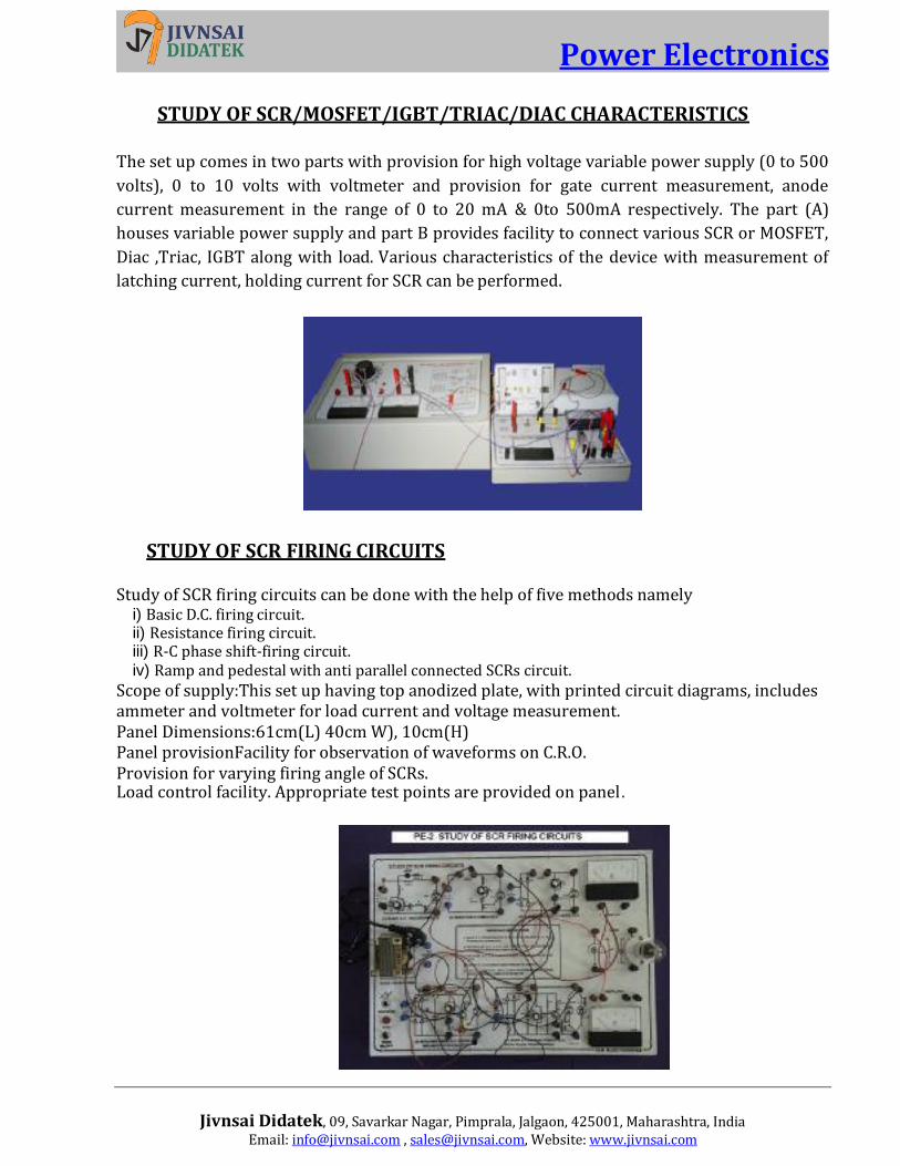
STUDY OF SCR FIRING CIRCUITS
Study of SCR firing circuits can be done with the help of five methods namely i) Basic D.C. firing circuit. ii) Resistance firing circuit. iii) R-C phase shift-firing circuit. iv) Ramp and pedestal with anti parallel connected SCRs circuit.
Scope of supply:This set up having top anodized plate, with printed circuit diagrams, includes ammeter and voltmeter for load current and voltage measurement. Panel Dimensions:61cm(L) 40cm W), 10cm(H) Panel provisionFacility for observation of waveforms on C.R.O. Provision for varying firing angle of SCRs. Load control facility. Appropriate test points are provided on panel.

Power Electronics
Jivnsai Didatek, 09, Savarkar Nagar, Pimprala, Jalgaon, 425001, Maharashtra, India
Email: [email protected] , [email protected], Website: www.jivnsai.com
JONES CHOPPER 25 V d.c. 1A fixed power supply for the chopper and d.c. Voltage is chopped down by main thyristor and commutating thyristor for variation of output from voltage of 5 to 20 volts by varying the on time control and frequency control of the chopping frequency circuit of the main thyristor. Optional analog voltmeter provided for measurement of output voltage. Appropriate test points provided. Size: 52 * 31*10cm (L*B*H)
MORGAN’S CHOPPER
A fixed d.c. Voltage of 25 volts provided for the input of chopper and the same is chopped down to vary from 5 to 20 volts by a single thyristor and resonating L-C circuit. Variable load facility provided. The frequency of chopping also can be varied. Waveforms can be observed with the test points provided on the panel. It is a self- contained unit. Panel size:52*31*10 CM.(L*B*H)

Power Electronics
Jivnsai Didatek, 09, Savarkar Nagar, Pimprala, Jalgaon, 425001, Maharashtra, India
Email: [email protected] , [email protected], Website: www.jivnsai.com
SERIES INVERTER
D.C. unregulated voltage provided for inverter and frequency control potentiometer to vary the firing frequency and the output frequency of series inverter in a limited range.25 watt, 230 V output. Panel size: 61*40*10 cm. Anodized top plate with schematic diagram neatly labeled with appropriate test points 8 Amp. 600V SCR are used.
PARALLEL INVERTER
D.C. unregulated voltage provided for inverter, Mcmurray Bedford type inverter with fixed frequency provided. Inverted output stepped up to drive 2No.230 volt 15W lamps at 50 Hz..Size: 61*40*10 cm.

Power Electronics
Jivnsai Didatek, 09, Savarkar Nagar, Pimprala, Jalgaon, 425001, Maharashtra, India
Email: [email protected] , [email protected], Website: www.jivnsai.com
CHOPPER MOTOR CONTROLLER
This is a d.c. Chopper circuit for getting a variable D.C. Voltage by using on time control and frequency control to feed a 110V load. Circuit demonstrates the use of chopper circuit for smooth speed variation of d.c. motor. Ammeter, voltmeter and test points are provided. JONE’S CHOPPER PRINCIPLE USED FOR OPERATION. Scope of supply¼ HP, 110 Volt, D.C. Series motor mounted on rigid base, 360(L)*250(W)*250(H) mm dimension aprox, BOX TYPE PANEL SUPPLIED Lamp load optional. Anodized & printed aluminum plate on the front panel.
SINGLE PHASE CYCLOCONVERTER
Panel Dimensions:600 (L)*500(W)*100(H) mm approx. 30-0-30 volts a.c. at 50 Hz provides input for a cycloconverter thyristorised bridge from which output is obtained at 25 Hz, 16.66 Hz and 12.5 Hz thus demonstrating the frequency reduction to ½,1/3 and ¼ of the a.c. mains frequency using digital logic circuits. Output of digital logic circuits are coupled to the thyristor gates by using opt isolators. All the waveforms can be observed with the help of the test points. Only lamp load of 24 volt ,30 watt can be used for this set up.
Power Electronics
Jivnsai Didatek, 09, Savarkar Nagar, Pimprala, Jalgaon, 425001, Maharashtra, India
Email: [email protected] , [email protected], Website: www.jivnsai.com
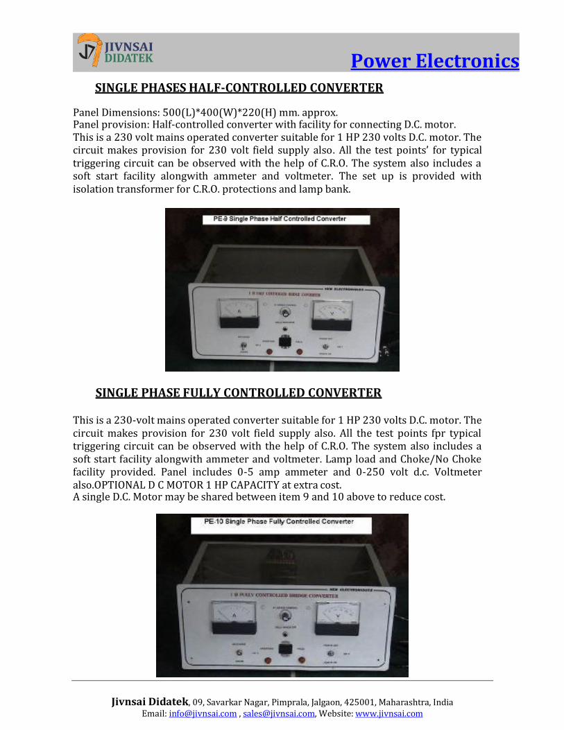
SINGLE PHASES HALF-CONTROLLED CONVERTER
Panel Dimensions: 500(L)*400(W)*220(H) mm. approx. Panel provision: Half-controlled converter with facility for connecting D.C. motor. This is a 230 volt mains operated converter suitable for 1 HP 230 volts D.C. motor. The circuit makes provision for 230 volt field supply also. All the test points’ for typical triggering circuit can be observed with the help of C.R.O. The system also includes a soft start facility alongwith ammeter and voltmeter. The set up is provided with isolation transformer for C.R.O. protections and lamp bank.
SINGLE PHASE FULLY CONTROLLED CONVERTER
This is a 230-volt mains operated converter suitable for 1 HP 230 volts D.C. motor. The circuit makes provision for 230 volt field supply also. All the test points fpr typical triggering circuit can be observed with the help of C.R.O. The system also includes a soft start facility alongwith ammeter and voltmeter. Lamp load and Choke/No Choke facility provided. Panel includes 0-5 amp ammeter and 0-250 volt d.c. Voltmeter also.OPTIONAL D C MOTOR 1 HP CAPACITY at extra cost. A single D.C. Motor may be shared between item 9 and 10 above to reduce cost.

Power Electronics
Jivnsai Didatek, 09, Savarkar Nagar, Pimprala, Jalgaon, 425001, Maharashtra, India
Email: [email protected] , [email protected], Website: www.jivnsai.com
THREE PHASE FULLY CONTROLLED CONVERTER
Panel: Box typePanel Dimensions: 500(L) *400(H)*300(W) mm approx. Panel provisions: 0-3 amp. Ammeter for load Current Measurement. 0-230 volt D.C. Voltmeter for output D.C. voltage.1 HP motor is optional at extra cost. Input 440 volts 3 phase, 50 Hz. 4 wire is stepped down with the help of 6 no. of transformers to form a 170 volt 3 phase system with current capacity of 4 amps. The system includes elaborate triggering circuit arrangement for a six thyristor fully controlled bridge converter with various test points and soft start facility and ammeter and voltmeter. 1 H.P. 230 volt D.C. motor can be driven from the output of this fully controlled converter. The system is provided with load bank.
THREE PHASE HALF CONTROLLED BRIDGE CONVERTER With star/delta connection facility.Panel: Box type. Panel Dimensions: 630(L)*300(H)*260(W) approx. Panel provision. 0-5 Amp Ammeter for load current measurement. 0-230 volt. D.C. voltmeter for output D.C. voltage measurement. Provision for varying of output D.C. smoothly. Facility for observation of attenuated output waveform on C.R.O. Appropriate test points brought on the side panel. Lamp bank as static load provided with the equipment.

Power Electronics
Jivnsai Didatek, 09, Savarkar Nagar, Pimprala, Jalgaon, 425001, Maharashtra, India
Email: [email protected] , [email protected], Website: www.jivnsai.com
THREE PHASE INDUCTION MOTOR SPEED CONTROLLER
(SLIP POWER RECOVERY SCHEME)
1 kw induction motor slip ring type is coupled to D.C. Generator 1 H.P capacity is supplied along with the set up, for demonstration of speed variation of induction motor. Ammeter/Voltmeter is provided along with the set up. Electronic controller includes power supply, firing cct , contactor & 1 phase SCR bridge inverter along with 6 diode bridge converter for rotor side. DV/Dt protection for thyristor included. Various test points are provided. Limiting resistance and choke are mounted on a separate base. D.C. generator o/p can be measured with separate voltmeter & ammeter mounted on the panel. This d.c. generator is used to load induction motor in a smooth fashion.
SINGLE PHASE FULLY CONTROLLED CONVERTER AND HALF CONTROLLED CONVERTER.(COMBINED UNIT)
24 volts a.c. voltage is converted into D.C. with the help of single phase half-controlled converter, or fully controlled converter. It is an open model where all test points can be safely and thoroughly tested without use of any isolation transformer for observation of waveform, Resistive load and R.L. load both can be provided for the output side of the converter. Importance of proper phase relationship for reference signal and line voltage can be demonstrated for single phase fully controlled converter. Panel: Board model. Dimension: 400(L)*200(W)*100(H) mm. approx.

Power Electronics
Jivnsai Didatek, 09, Savarkar Nagar, Pimprala, Jalgaon, 425001, Maharashtra, India
Email: [email protected] , [email protected], Website: www.jivnsai.com
UNIVERSAL (AC/DC) MOTOR CONTROLLER
This unit comes with ¼ HP, 230 volt A.C./D.C. motor which can be controlled from 230 volt. a.c. mains. The firing circuit produces +ve & –ve voltage depending on the setting of the speed control knob and this setting can also control direction of rotation of the motor in a single control, for d.c. operation.A.C. operation can be tested over a limited range of voltage. Appropriate test points are provided. Scope of supply: ¼ HP, 230 volt A.C./D.C. motor with loading arrangement, along with triac controller.Panel: Board Model. Panel Provision:Triac used to achieve the variable voltage control for (AC/DC) motor.Built in facility for D.C. voltage. Balance and gain adjustment pots are provided.Ammeter 0-2 Amp. for measurement of load current.(optional) Appropriate test points are provided.
STUDY OF COMMUTATION METHODS
This set up facilities the study of all the commutation methods on a single panel. The various commutation methods covered include Class A, Class B, Class C, Class D, Class E, and finally Class F operation All the required thyristors, power supply, inductors, Capacitor banks, firing circuit capacitors are provided on a single board. The student himself has to patch up the circuit for a particular class of commutation methods. Appropriate test points for observation of waveforms provided. Panel Size:60cm.* 60cm.* 5 cm.(L*B*H).

Power Electronics
Jivnsai Didatek, 09, Savarkar Nagar, Pimprala, Jalgaon, 425001, Maharashtra, India
Email: [email protected] , [email protected], Website: www.jivnsai.com
SINGLE PHASE INVERTER USING POWER MOSFET IN BRIDGE CONFIGURATION
4 no. of power MOSFETs are connected to the D.C. Source (built in) and circuitry is provided to get a square wave a.c. source with variable frequency. Selection of low frequency and high frequency can be made. Low frequency A.C O/P is stepped up by an O/P transformer, to drive a 40-watt, 230 volt lamp load. For higher frequency operation only resistive load is provided. All the required test points are provided. The system is laid out on a neatly labeled polycarbonate panel with clear marking of the various components and schematic circuits diagrams Opto isolators are provided in driver ccts for power stage. Model size: 60*40*15 cm. approx.
CHOPPER CIRCUIT USING POWER MOSFET/IGBT (Chopper Motor Controller)
The system demonstrates the application of power MOSFET/IGBT to generate a variable D.C. voltage in two ranges, 1) 6 to 24 volts and 2) 10 to 100 volts typically. The chopper frequency can be varied in the range of 30 Hz to 150 Hz with duty cycle varied for 10% to 90% typically. The O/P can drive a 24-volt/30 watt lamp or ¼ HP 110- volt D.C. series motor or 110 volt/60 watt bulb also. Provision is made for all the three loads. You may connect a portable power tool for demonstration. All the components are neatly laid out on anodized panel with block schematic printed on it with various test points. Only ¼ HP D.C. series motor 110 volt is supplied at an extra cost. Model size: 60*40*15 cm.

Power Electronics
Jivnsai Didatek, 09, Savarkar Nagar, Pimprala, Jalgaon, 425001, Maharashtra, India
Email: [email protected] , [email protected], Website: www.jivnsai.com
STEP UP CHOPPER
Step up chopper with built in power supplies, frequency variable between 20 Hz to 100 Hz with duty cycle variable in the range 10% to 90% with 40 watt load. Completely self- contained unit on a neatly labeled anodized plate and detailed instruction manual. I/p 20 volt d.c. is stepped up to 200 volt d.c. through this step up chopper using power mosfet, inductance and high voltage condenser. Suitable test points are also provided. Panel size: 52*31*4 cm.(L*B*H)
D.C. DRIVE TRAINER. (Using Dual Converter) This system makes the use of industrial version of d.c. drive using dual converter there by facilitating motor speed control in both the directions from a single potentiometer. The drive also has built in PID controller for speed regulations. D.C. motor ½ HP/200 volts, 1500 RPM with loading arrangement is provided and dynamic braking of the motor also can be demonstrated. Over current protection is provided. The unit comes with appropriate test points and an ammeter. It has neatly labeled front anodized panel with block schematic clear view of the system. Isolating transformer is provided for waveform observation on C.R.O. Model size: 50*80*22 cms.
D.C. CIRCUIT BREAKER USING SCR The solid state switching characteristics of SCR can be used to advantage for cct making and breaking in a d.c. cct involving high currents. Electro mechanical switching involves log of sparking and resultant wear and tear of contacts. The set up is designed to demonstrate this aspect very clearly. D.C. Power supply with 25 volts 4 amp capacity, main thyristor, auxiliary thyristor & commutating capacitor with start and stop switches are provided. Power control through relay is also included. The system is placed on neatly labeled polycarbonate elegant panel printed with circuit diagrams.

Power Electronics
Jivnsai Didatek, 09, Savarkar Nagar, Pimprala, Jalgaon, 425001, Maharashtra, India
Email: [email protected] , [email protected], Website: www.jivnsai.com
3 PHASE INDUCTION MOTOR CONTROLLER USING V/F SCHEME
& PWM METHOD for 0.5 H.P,230 volt ,3 phase induction Motor
V (voltage) /F (Frequency is variable) & V/F ratio can be calculated and is maintained almost constant. F is variable & indicated by digital indicator and voltage is indicated on analog meter. The system operates to keep V/F ratio constant under software control of microprocessor. The power device is IGBT using PWM technique. Students can study all the functions such as acceleration time, deceleration Time, Over current protection, stall prevention, Motor direction control. Meters are provided to measure input A.C. line current and O/P A.C. Voltage. Test point and isolating transformer is provided to see PWM O/P waveform Unit comes With 0.5 H.P., 230 V, 3 phase, induction motor and loading arrangement.(INDUSTRIAL VERSION Controller)
STUDY OF UPS TRAINER The UPS system as trainer unit is provided with Basic Off Line UPS card with a)Power MOSFET inverter (300 VA capacity) b)Input dimmer c)voltmeter, which can be used to check the I/P an O/P A.C. Voltages. There is a provision for providing input A/C direct from mains supply or through the dimmer. This facility makes it possible to study the effect of incoming line voltage changes on the output. d) 15 min back up time battery is provided with the unit .e)Test points are provided to study PWM stage O/P, Final O/P Of the inverter ,mains a.c.input stage. The unit comes with powder coated sturdy box along with Load bank. Panel Size:59*29*30cm
VOLTAGE COMMUTATED CHOPPER
24 V D.C. 1 A fixed power supply provided for chopper and d.c. voltage is chopped down by main thyristor and auxiliary thyristor (commutating thyristor ) for variation of O/P voltage of 5 to 20 V by varying on time control & frequency control of chopping frequency circuit of the main thyristor. Commutation of the main thyristor is carried out by Voltage commutation principle. Appropriate test points are provided. Panel Size:52*31*10cm

Power Electronics
Jivnsai Didatek, 09, Savarkar Nagar, Pimprala, Jalgaon, 425001, Maharashtra, India
Email: [email protected] , [email protected], Website: www.jivnsai.com
SINGLE PHASE PWM INVERTER USING POWER MOSFET/IGBT
This demonstration unit demonstrates single phase pulse width modulator inverter (PWM) based on IC SG3524. The system comes with built in D.C. power supply(15volts 4amp capacity), Ammeter. This D,C, voltage is inserted into almost square wave A.C. by means of S.G.3524, 2 No. of power MOSFETS (IRFP250N or equivalent or IGBT). Center tap output transformer and lamp load of 40 watts,230 V. The pulse width can be controlled in a wide range thus varying the output voltage. Waveforms can be observed on test points provided. Current limiting and shutdown functions also can be studied. The entire system is mounted on elegant anodized plate with neat labels, circuit diagrams etc. A detailed instruction manual along with circuit diagrams will also be provided. The unit is typically a board model with approx. size of 52 * 31* 10 CM (L * B * H)
STUDY OF IGBT CHARACHTERSTICS
The system is designed to study the transfer characteristics of IGBT.The setup is provided with a variable D.C.supply in the range 0-30 volts, which has good regulation up to 1.5 amp d.c. load current.This variable supply is used to vary the collector to emitter supply. The gate voltage (Vgs) is derived from regulated 12V d.c.supply & is made variable from 0 to 12 V by means of simple potential divider .The panel includes an ammeter ,holder for lamp and provision for connecting external load resistance when lamp is not used.Gate and collector supply controls are provided. It is also possible to use external d.c.voltage by connecting the same at the marked terminal on the panel. Neatly labeled polycarbonate panel is used for the setup along with Powder coated M.S. Box.. Detailed Technical Manual accompanies the system.

Power Electronics
Jivnsai Didatek, 09, Savarkar Nagar, Pimprala, Jalgaon, 425001, Maharashtra, India
Email: [email protected] , [email protected], Website: www.jivnsai.com
STUDY OF IGBT DRIVERS
The setup is designed to demonstrate typical circuits for driving IGBT and are divided into two schemes.1)Isolated scheme 2)Unisolated scheme. The system provides an isolated d.c.source of 40V and an isolated load (lamp).By proper connection of patch cords, d.c.supply and load can be connected into the two schemes .This is indicated on the front panel also.PWM waveform generator circuitry is provided on board . IGBT 402 is used in this system. Duty cycle and frequency controls are provided on board. Appropriate test points are also included. Neatly labeled polycarbonate panel and powder coated M.S. Box is used for the setup. Detailed Technical Manual accompanies the system.
SCR Regulated power supply
The SCR regulated power supplies are more efficient than any of the series pass circuits using transistors. When SCR is OFF , it blocks current and when ON it drops a very small voltage across it thus ensuring little power is lost across it. The set up is developed to demonstrate the working of an SCR regulated power supply with half controlled bridge converter operated from a step down transformer so that average o/p voltage can be varied by changing the firing angle of SCRS. Early gating produces high dc voltage and late gating produces, lower voltage . An error amplifier compares the reference voltage with a sample of the load voltage and any difference will change the gating of the SCRs and reduce the error. The system includes ammeter ,voltmeter and loading arrangement on a neatly labeled poly carbonate panel. Range :24 volt ,2amp capacity. Regulation: Good
Study of SCR flasher
The different types of flashers are basically power flip –flops and are used in a variety of applications such as traffic signals , navigating beacons etc. The SCR or triac offer advantage over power transistor in that they do not require excessive derating of current to handle inrush current for incandescent lamps In the set up designed to demonstrate the working of SCR flashers ,we have 1.UJT relaxation oscillator with controllable frequency 2.2 No thyristors 3.Necessary power supply 24 volt for lamp load. 4.1No. of lamp 24 volt ,30 watt. 5.Appropriate test points. Detailed cct diagram is printed on a polycarbonate panel for easy understanding for students. Detailed manual comes with the system

Power Electronics
Jivnsai Didatek, 09, Savarkar Nagar, Pimprala, Jalgaon, 425001, Maharashtra, India
Email: [email protected] , [email protected], Website: www.jivnsai.com
Study of Zero voltage switches The zero point switches are highly desirable in many applications because they do not generate electromagnetic interference (EMI).A zero point switch controls the sine wave power in such a way that either complete cycles or half cycles of power supply voltage are applied to load . This type of supply is primarily used to control power to resistive load for heating. Two schemes one using op-amp and other using voltage comparator ICLM339 are used, with built in power supply and variable input signal at 50HZ The set up is useful to develop complete understanding of the principle with the help of cct diagram printed on polycarbonate board and resultant cct operation of the system.
Study of SCR Alarm A burglar alarm is demonstrated in this set up by using a light dependant resistance (LDR) as a sensor and SCR as a latching device. As long as the light incident on LDR is not interrupted by an intruder, the buzzer remains off. If the light is interrupted once, the relay is turned on by the comparator circuit in conjunction with SCR. The relay turns on and because SCR is turned on, unless the reset or alarm acknowledge button is pressed, it will not turn off. The entire system is placed on a neatly labeled elegant polycarbonate panel for proper understanding by the students. It is a self-contained unit with input power at 230 volt 50 volts main.
Modified McMurray –Bedford half bridge inverter
The system is having built in D.C. supply of (+22)-GND (-22) Volts with the help of step down transformer TR1 with secondary 0-15,0-15 at 4 amps each.Another 15Volts are used for UJT oscillator supply.The thyristors used are 2N4103 with individual fuses & also additional fuses for each of the power supplies .The switch SW1 is used to supply dual polarity supply to the system .Before turn on of the mains ,the SW1 has to be in off position (left side) .So when system is connected to mains supply,the two LEDs near the power supply are lit up indicating presence of power supply.The D.C. for UJT oscillator is available & you can check waveform for UJT oscillator ,(across the capacitor saw tooth waveform). TP1 &TP2 for both gates & cathodes of TH1 &TH2. Pot P1 is frequency control pot.TR2 is center tapped inductance whereas TR3 is O/P transformer for 230V 25 watt lamp load. When SW2 is in downward position ,simple resistive load is turned on ,while with SW2 in upward position the lamp load with step up transformer is brought into action .The voltage O/P (A.C.) waveforms can be observed for both lamp load and simple resistive load. The entire setup is included with block schematic. As well with neat labels for various components.

Power Electronics
Jivnsai Didatek, 09, Savarkar Nagar, Pimprala, Jalgaon, 425001, Maharashtra, India
Email: [email protected] , [email protected], Website: www.jivnsai.com
Study of SMPS
This system enables the students to develop complete understanding about working of typical SMPS by using various test points.(For observations on CRO ). Effect of the line voltages and effect of load current changes. The Setup is laid on a neatly labeled polycarbonate panel with isolating transformer ,ammeter, loading system and facility to effect input voltage changes. Panel size 38cm * 26 cm
Permanent Magnet Brushless DC Motor (PMBLDM) Drive trainer
Specifications: Input: 230V AC ,Armature Voltage :24V DC ,Armature Current:5A DC Max ,Speed variation: By potentiometer ‘Feedback: Hall sensor Motor type:PMBLDC ,RPM:1500RPM,Torque:6kg cm. Speed selection by Pot or by 0 to 10V dc. Optically isolated enable, Direction and Brake commands. Isolated speed feedback, Unit comes with neatly labeled front panel , loading arrangement for Motor.