Embed Size (px)
Citation preview
Dr. S. & S.S. Ghandhy GEC, Surat. electrical
Topic : basic control system
ENROLLMENT NO. NAME
130230109004 SAGAR BARVALIYA130230109013 MARVIN GAJERA130230109024 PAVAN LETHWALA130230109028 MITESH GANDHI130230109033 PARESH PARMAR130230109047 PARESH RANA130230109052 HARDIK SAPRA130230109059 URVIK VASAVA
Guided by:
“ It is an arrangement of different physical elements connected in such a manner so as to regulate, direct or command itself to achieve a certain objective.”
What is control system?

AccuracySensitivityNoiseStabilityBandwidthSpeedOscillation
Requirements of a good control system
a)Open loop system
b)Closed loop system
Classification of system
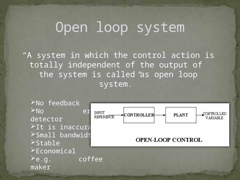
Open loop system“A system in which the control action is totally
independent of the output of the system is called as open loop system.”
No feedbackNo error detectorIt is inaccurateSmall bandwidthStableEconomicale.g. coffee maker

Closed loop system
“A system in which the control action is somehow dependent on the output is called as closed loop system.”
Feedback existsError detector is presentAccurateLarge bandwidthMay become unstableCostlyE.g. guided missile.

Transfer function
Systemg(t) c(t)r(t)
“The transfer function of a linear time invariant system is defined as the Laplace transform of the impulse response,with all
initial condition set to zero.”

Block diagrams“block diagram is pictorial
representation of the cause and effect relationship between input and output of
the system.”
Block diagram of physical systeminput output

Time domain analysis“The response of a system to an applied
excitation is called time response and it is a function of time. It is denoted by c(t).”

Transient & steady state responseTransient response: “That part of the time response which goes to zero as time becomes very large is called as transient response.”
Steady state response: “The part of response that remains after the transients have died out is called as steady state response.”
Damping Factor And Natural Frequency Of Oscillation
1.Damping ratio: the damping is measured by a factor called as damping ratio.It is denoted by ‘ξ’ .
2. Natural frequency of oscillation: when ‘ξ’ is zero; that means there is no opposition to the oscillatory behaviorof a system will oscillate naturally.

System Stability BoundsStable system : if a bounded input is given to the system ,the response of the system is bounded and controllable ,then the system is called stable
unstable system : a linear time invariant system is unstable if the system is excited by a bounded input and output response is unbounded.
Absolutely stable system : if a system response is stable for all variations, it is called absolutely stable system .
Critically stable system : the output does not go on increasing infinitely nor does it go to zero as time increases that’s called critically stable system.

Automatic Controllers I. Two Position Or ON- OFF Controllers
II. Proportional Controllers…..[P]
III.Integral Controllers….[I]
IV.Proportional+integral Controllers [Pi]
V. Proportional+integral + Derivative Controllers [Pid]
VI.Proportional + Derivative Controllers [Pd]
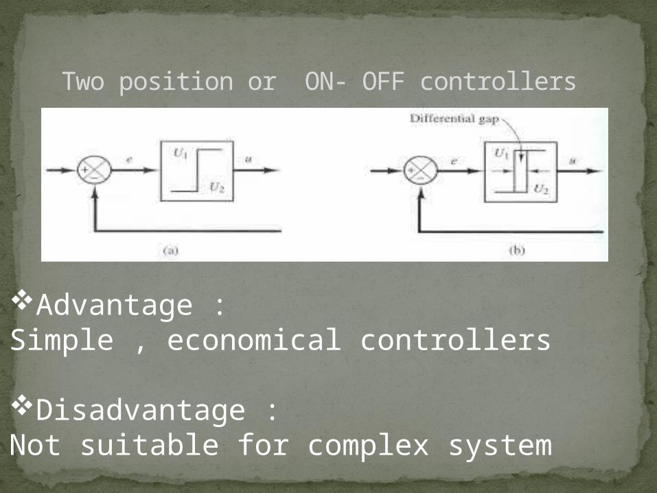
Two position or ON- OFF controllers
Advantage :Simple , economical controllers
Disadvantage : Not suitable for complex system
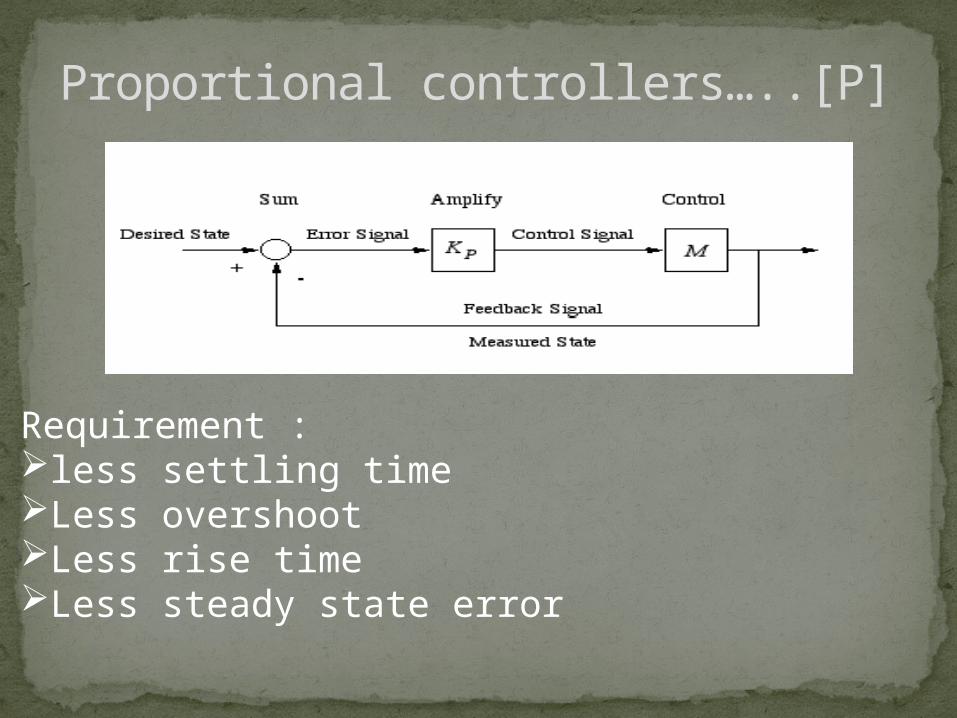
Proportional controllers…..[P]
Requirement : less settling time Less overshoot Less rise time Less steady state error

DIGITAL CONTROL SYSTEMMost digital control apps employ
computer for effective control action.There are two approaches to using
computer for control:1. Supervisory Control2. Direct Digital Control(DDC)

Supervisory Control:Supervisory control
emerged as an intermediate step where in the computer was use to monitor the operation of analog control loop and to detemine appropriate set points.
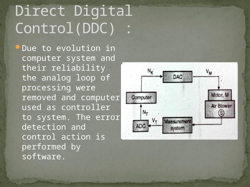
Direct Digital Control(DDC) :Due to evolution in
computer system and their reliability the analog loop of processing were removed and computer used as controller to system. The error detection and control action is performed by software.

Application of DCS
•Electrical power grids•Traffic signals•Radio signals•Oil refining plants•Chemical plants•Sensor network•Water management systems

Automotive control focuses on the following issues : modeling , supervisison,control and diagnosis of automotive system, automotive power trains, propulsion, vehicle dynamic systems, intelligent driver aids, electric, fuel cell , hybrid and alternative drive vehicle.
Automotive control has gone to work off road through expertise and extensive product portfolio. With various propel system solution, machines can now offer advanced automatic transmission functionally. When the operator depresses the accelerator , both the engine rpm and hydrostatic pump and motor displacement are controlled automatically.
Automotive Control

Wheel LoaderTelescopic HandlerRotary TelehandlerTool CarrierRough Terrain ForkliftTruck Mounted ForkliftSite DumperCompactorSpecialty Transporter
Application of Automotive Control
Air Craft Control
•A convincible fixed wing air craft flight control system consist of control system surface, connecting linkage, cockpit controls and necessary operating mechanism to control air crafts direction in flight.
•The fundamental of air craft control are explained in flight dynamics. This article centers on the operating mechanism of flight control.
1. Primary control2. Secondary control3. Air craft control and movement
PRIMARY CONTROL
The primary cockpit controls are arrangement as follows:
1. Controls column or control yoke attached to control column for roll and pitch
2. Rubber paddles to control yaw which move rubber, left foot forward will move the rubber left for instance.
3. Throttle control to control engine speed or thrust for powered air craft.

SECONDARY CONTROLS
•The secondary controls available to give the pilot finer control over flight or to ease the workload.
•The most commonly available control is a wheel or other device to control elevator tree so that pilot doesn’t have to maintain constant backward or forward pressure to hold a specific speech attribute.
•Aircraft have wing flaps control by switch which improve control at the slower speed use for takeoff and landing.
•Other secondary flight control system may be including slats spoilers, air brakes, variable sweep wings.

AIRCRAFT CONTROL AND MOVEMENTS
There are three primary way for aircraft to change its orientation relative to passing air.1. Pitch2. Roll3. Yaw
PITCH : is control by the real part of tail planes, horizontals stabilizer being hinged to create an elevator. By elevator the pilot moves elevator up and downward force on the horizontal tail is increase. The pitch control much simple so when the pilot moves the elevator control backward, it produce nose down pitch and the angle of attack is reduced.
ROLL : to achieve angle of bank when desired change of handling.
YAW : is induced by a movable rubber attached to vertical field usually at the rear of air craft. On a large air craft they may be several independent rubber on single fin for safety and control the inter-linked yaw and roll action.

Missile guidance refers to a variety of methods of guiding a missile or a bomb to its intended target . guidance system improves missile accuracy by improving “single shot kill probability”(sskp).
Missiles and guided bombs generally use similar types of guidance system, the difference between the two being that missiles are powered by an onboard engine , whereas guided bombs rely on the speed and height of the launch aircraft for propulsion.
Missile Guidance

Guidance systems divided into two categories:
1.Go-Onto-Target(GOT)guidance system: it can target either a moving or fixed target.
2.Go-Onto-Target-Location-in-Space(GOLIS) guidance system: it needs to be eliminated in a timely fashion in order to preserve the integrity of the sender
Categories Of Guidance System
DISTRIBUTED CONTROL SYSTEAM•Collection of hardware and instrumentation necessary for implementing control systems
•Provide the infrastructure (platform) for implementing advanced control algorithms
FUNCTION REQUIRED
1. System availability requirements2. System load3. System response4. Environmental requirements

DISTRIBUTED CONTROL SYSTEAMADVANTAGES
1. Data presentation is in a systematic format enabling easy comparison of various parameters and taking decision by a printer
2. Logging of data is done by a printer thereby eliminating human error.
3. Complex computation analysis etc. can be carried out easily.
4. The system is flexible. i.e. changes in systems can be easily made.
DISADVANTAGES
5. To access the data generated by system skills operating required.
6. Failure of one controller effect more than one loop hence it calls for very high MTBF can high degree of


![[CONTROL ] Basic Control Theory](https://img.pdfslide.us/doc/110x75/577cd4f51a28ab9e789992b8/control-basic-control-theory.jpg)