Embed Size (px)
Citation preview
b ffAr'ï
GOVERNM ENT OF BALOCHISTAN
BALOCHISTAN COM M T'NITY IRRIGATIONAND AGRICULTURE PROJ ECT
BCIAP DESIGN MANUI\LPART 4: INFILTRATION GALLERIES
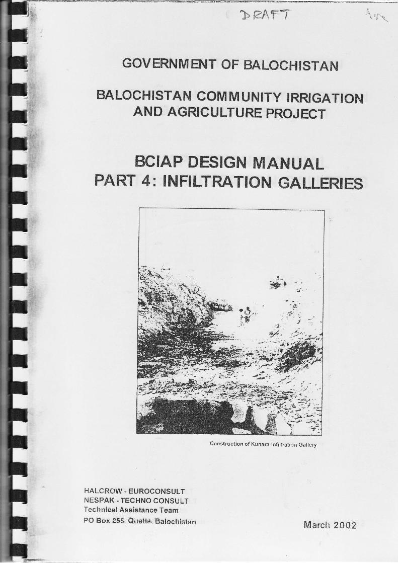
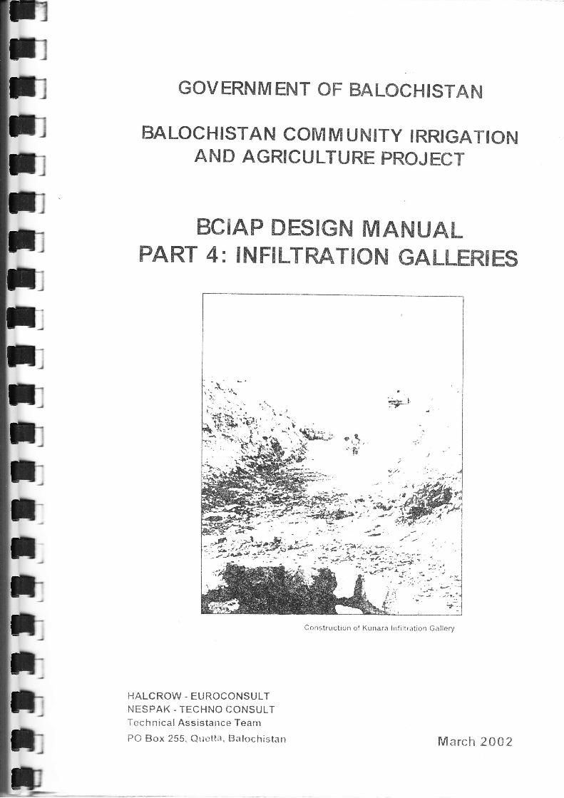
Construction of Kunara Infiltration Gallery
HALCROW. EUROCONSULTNESPAK - TECHNO CONSULÏTechnical Assistance TeamPO Box 2SS, QuËttíi, Balochistan March 20Az
GOVERNM ENT OF BALOCHISTAN
BALOCHISTAN COM M UNITY IRRIGATIONAhID AGRICULTURË PROJECT
BCIAP DESIGN MANUALPART 4: INFILTRATION GALLER|ES
HALCROW - EUROCONSULTNESP,AK - TECHNO CONSULTTechnical Assistance Team
PO Box 255. Qur-.tt;, Balochistarr M arch 2A02
I
z
GOVERNMENT OF BALOCf-t ISTANBALOC H ISTAN COMMU NITY IRRIGATION AN D AG RIC U LTU RE PROJECT
DESIGN MANUALPART 4 - INFILTRATION GALLERIES
TABLE OF CONTENTS
lNTRoDUcrloN ..................1
GALLERY LOCATTON AND ORTENTATTON .......52.1 Introduction 52.2 Command............ s2 3 River Stability.....
..... ............52 4 Water Depth, Depth to Rock and Scour Depth......... ...................62.4.1 Depth of Gailery... ...........62.4.2 Scour Depth......... ........."..62 5 Ownership of the Site...... .............82ulCi:rlleryorientation,Guide-bundsandCut-offs......
CON STRUCTION3 1 lnirodr:ction3 2 Reinforced Concreter 3 Blockwork......3 -1 Perïorated Concrete Pineq-: 5 Galvanised Perforated Corrugated Steel Drainage pipes........... , GalleryAcccss Manholer / Di:irvery Plpeline Í\4anholesi Cnrrstrtrt:tion Sequence and Deuaterinct
.1 HYDRAULIC DËSIGN-: I llirocirictron ......: I Srrrf.tce Flows
-'-' / lnfiltralion Rate.: 2 2 FilterPernreabilitv.
2'3 S/oÍted Area....: 2 -j lvíaintenanceSrrl,-sudace Flows...-l i, ifirc;e anci Sub-surface Flowsi ,i L octlti()n iln..i Slotteci Area.r.r i r.i Pilteline,'Conduit.
.9
.9
.9ItJ
10101'l
17títl17
18totó
..19
...21..21
a.)
FiLTER DESIGN.: rilrli-l:ll
- si.: ii:l ), T;tppir_''g
-: '.i.t ir-rv Ta;lping
27aaLI
2727
STRUCTURAL DESIGN' Gcrlêrêl
' : ] lrf. ,,'.,:lls
a : ^r ti -i._r!rir(:L- l.iilt-.t
'_id I
_. ,_i 2 Concrete Bedding.....
-:;endix A Worked Example
3:ci r ography
Sub-surface FLowSurface Flow
Ucl i(-. .
Pino R,r,-ldinn'u.'Granular Bedding
31a4
'71
????
.,\J
?Jl
36

GOVERNMENT OF BALOCH ISTAN
COMMU N ITY IRRIGATION AND AGRICU LTU REBALOCHISTAN
CONTENTS OF OTHER PARTS
Part 1 Site Investigations
Par12 Flood Estimation
Part 3 WeirsParl 4 Infiltration Galleries
Part 5 lrrigation Canals
Part 6 lrrigation Strudures
Part 7 Flood Protedion
Part B Potable Water Supply Systems
Par19 Structural Design Criteria
Part 10 Draughting Standards
Parl 1 lValue Engineering
Part 12 Standard Drawings
PROJECT
DESIGN MAÀIUAL
GOVERNMENTOFBALOCHISTAN .
BALOCHISTAN COMMUNtry IRRIGATTON AND AGRICULTURE PROJECT
DESIGN MAT.IUAL
Conversion Factors
Lengtlt1 inch1 foot (12 inches)1 miie (5280 ft)
Area1ft2.1 acre (43,560 ft2)
1 sq. mile (640 acres)
Volume1ft335.315 ft3
;'jeiqhts \
ilo:2 rb
t tcn (US)
l;schareer cusec (ft'ris)
= 25.4 mm
= 0.3048 m- 1609 m
0.093 m2
0.4A47 hectares gA47 mz)259 hectares
= 0.028 m3
= 1m3
= 0.454 kg
= 1.0 kg
= 907.2 kg (0.902 tonnes)
= 0.028 cumecs (m3/s)
IIIrII
BCIAP DESIGN MANUAL PART 4: INFILTRATIoN GALLËRIES
Itrfiltration gallefies are one of three methods used in Balochrstan at present toperennial flow from rrver beds, the other two being weirs and free intakes. lnfiltratjonare preferred over the other trao alternatives rn the foliowing circumstances:. where a Íree intake would be unreliable,
INTRODUCTIONThis Manual is based on the Bf\4lADP lnfiltration Gallery Design Manual. The Manuai coversail aspects of infiltration gallery design and construction and this revised edition rncludes
:::jru3'iËterial based on the expórience gained rrom constructins weirs in Barochistan
An infiitration gallery is a perforated conduit constructed at depth in a river bed comprisingpermeabie material. Infiltration galleries are designed to tap subsurÍace flow in the rivergravels, or a combination of sub_surface and surface flow. Hcflow the firter media surrounding the gatery wi, quickry .n"';t""J;:J,,ffi:i:t:?:ij;:growth. Gaileries shourd therefore be used primariry to táp for sub_surÍace flow.
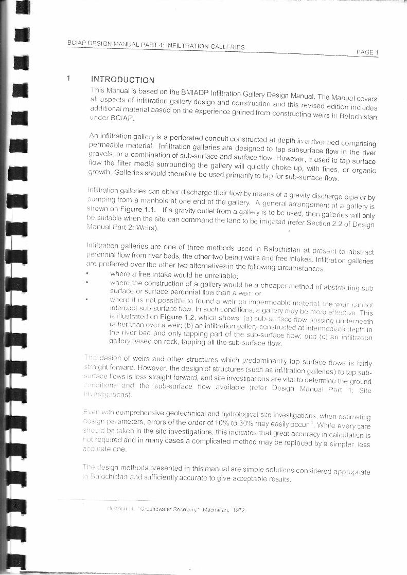
Infrltration galleries can either discharge their flow by rrieans of a gravity discharge pipe or bypumping from a manhole at one end of the gallery. A general arrangement of a garery isshown on Figure 1' 1' lf a gravity outlet from a gallery i! to oe used, then galleries will only
il:,:::ï3':Ji:il,i:r; ," can command the iand to be inigared (refer sectio n 2 2 of Design
PAGE 1
a bstractgalleries
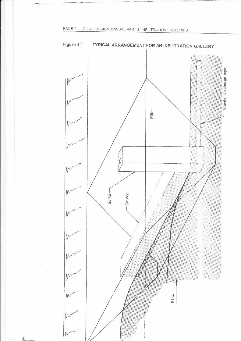
where the construction of a gailery wourd be a cheaper method of abstractirq suilsurface or sudace perennial fiow than a werr: orwhere it is not possible to founcl a weir on inipernreable rrraterial. tire w*ir c.innotintercept su[:-sufface fiow. In such conditions a glallery n,of lu nrore effcctrve Thisrs illtlstrated on Figure 1.2, which shows. (a) sLrb-sur1a." flo* lrassrírg.rdorneathr:ither than over a weir; (b) an infiltration gallery constructed at rnternrecJiirt* clepth intlte river bed and only tapping part of the sub-surface fiow; anct (c) an rrifrítratrongallery based on rock, tapping all the slb-surface flow.
iire design cf weirs and other structures which predomínantiy tap surface flours is fairlysli-aiqht forwarcJ However, the design of structures (such as infiitration gattenesjio r"p ,uo-si;rtace flor'vs is less straight forward, and site investigations are vital io cletermine the ctround''rrijitrotrs and the sub-sudace flow available lrefer Design M:rnual pirrt 1 siter. i'stril.rtrons)
-\r)rr \vitil conrprelrensive geotechnicaland hycJrological site rnvestigatrons..when estrmelrng-lesign parameters, errors of the order of 1o% to 30% mayeasilyo"..rr,. v,it..,ii"
"u*.y.ur*siroitlci betaken in the site investigatiors, this indicates that great accuracy in calculatron is:ot req'rireci and in many cases a complicated method may be repíaced by a simpler. less.ricurate one.
Tlre desicln rlethods presented in this manual are simple solutrons considered approp'aterl Salochistan and sufficienily accurate to give acceptabie results.
Hu silctn, L Groundwater Recovery.' lr,,lacntillan. 1972
PAGE 2 BCIAP DESIGN MANUAL PART 3: INFILTRATIoN GALLERIES
(l)ttloC).910
.;P
Íï#
ttr*
l:l::
'. i,.'.:,i.,.
,i..
Figure 1.1 wPlcAL ARRANGEMENT FoR AN tNF|LTRATION GALLERY
(I
cU)
lnJ'ru-
il{I'
^-/'l^/lv
JlM-"-I'
fiMJ"lv
il\d- )È\(u
E(9I
\,í,''',,,,,'.,',,,,,.i::::::'
f,rrr-lr
T
i
lÍ\./ "lr
]ol,!
Wt__
BCIAP DESIGN MANUAL PART 4: INFILTRATION GALLERIES
Figure 1.2 wEtR AND GALLERIES tN RtvER wlïH DEEP DEprH To BED RocK
: Shollow gollery
Ficw
Fítter
IrIrrtIIItttII
c Deep gcllery found on rock
Ë--
GrTIIT
ttTtIrlttTtttIt
z.r
BCIAP DESIGN IVIANUAL PART 4; INFILTRATION GALLERIES PAGE 5
22
GALLERY LOCATION AND ORIENTATION
IntroductionThe location and orientation of an infiltration gallery will be affected by a number of Íeaturesor factors. In most cases each of the features will have equal importance and the galiery sitewill have to be suitable to meet each of the criteria associated with these features. The mainfactors which affect the selection of the gailery site, the depth of the gallery and its orientation,ancJ which are discussed in detail below are:. Command;o river stability. wêter depth, depth to rock and scour depth;. ownership of the site; ande orientation, guide-bundsand cutoffs.
When considering a proposed new gallery site, each of these factors must be considered. lftire proposed gallery site does not meet all of the criteria then an alternative site should besought. lf a site cannot be found which satisfies all of the criteria, then a gallery should notbe constructed and alternativessuch as a free intake or a weir should be considered.
Commandli is rare, though not completely unknown, for Íarnring communitres to be prepared to take onthr-. res;-ronsrbilityof operating a communal pumped irrrgation qstem. An infiltraticn gallerysirolrld, therefore, normally be able to command the cultivated area by gravity. Obvroirsly, this
nreans that suffrcient fall needs to be allowed for to ensure that the outlet pipeline/conijuit anC
rlain channel can carry the design Ílow. The design of pumping rnstallations is aiso therefore
orrtsicle the scope of this Manual.
Chow recommends that all lined channels should have a mininiunr flow veloctty of 2 to 3 fl'srvirerr the percentage of silt present in the channel is small. lf the minimum flow velocity in a
Jrnecj clranrrel is 2 Sft/s then vegetation growth will be laroely :revented' In practtce, very
rouqhly tlris means that for flows above 10 cusec, the chani'el slope must excoccl abeut
il 001 ancj for snraller flows the channel slope nrust exceed al';Lrt 0.002.
Ríver StabilityAn icjeal callery site wculd be one where the river is stable, neither meandering nor degrading
nor aqraclrng.
Siryns that a river is meandering are often clearlyvisible. The cutside of bends will be being
t-r-o(iecl and srgrrs of river bank collapse are often visible. lt is ofien possible to see how much
;t ri',,er'lias nreanclered by compaling the present position of a river with that shown on the.i iiO.000 tcpographic maps of the Survey of Pakistan, which we-e last upclated in aboui 1957.
Sigrrs 1r;t a river bed isdeErading (lowering)oragracling (gra,uallybeing raisccl);rrr: often
ntori: ilifÍir;uit to spot. Local people ntay say that thi-'river level adjacent to i'ttr irrigatlon
stlircture or inlet has been lowered such that the river no lcr:ger cornmands their lands.()()nv()fscly, tlte. structLtre may be betng buried by1hi,' river.
Chorv, Vï Opr:tt Ch;rnnel H$raulics." lvÍcGrarrrHill, 1978.
PAGE 6 BCTAP DES|cN MANUAL pART 3: INF|LTRAT|ON GALLERTES
Some riversites are obviously not meandering, such as where ii: -
rock outcrops. other sites are inherenily unstable such as r.ir-ere - ,
plains and washout fans and braid into severalchannels He:= -move, but some channels can quickly become disused whiis: :-= -
for itself.
In practice, gallery's (like weirs) have to be constructed on ascme extent. In there isa risk of this then stone protected ou,c:to ensure that the gallery is not by-passed in the future. Simr a-river bed may be acceptable, whereas it will generally not be fc. :should be avoided as it poses an unacceptable risk of faiture :;
2.4 Water Depth, Depth to Rock and Scour Depth
2.4.1 Depth of GalleryThe depth of the gallerywill be determined by:
' the depth at which the maximum flow can be tapped. the depth to bedrock;. the maximum depth to which excavation is practical :. the maximum depth at wlrich command can still be a:,-. the minimum depth to avoid scour problems; and. the minimum depth to tap the sub-surface flow
The preferred depth of the gallery will be determined by h', :', -drscussed in detail in Chapter4. However, the maxim,,ri- t:considerations such as the depth of the permeable strata I :-costs. lncreases in the depth of a gallery increase the ccsi :' --
excavation for the gallery and pipeline and measures : -
corrstrurction. Also, tlre deeperthe gallery, the longer tlrt : :-=
The maxinrum cieptlr of the gallerymayalso be dictated:., :',
The principalfactor aifecting the minimum depth of the := =
damage. This applies to the filter media around the galler-. as .
system is to remain fully functioning after the passa:= :'construct galleries within the scour depth and proteci ti:e : = =
mattresses (refer ChapterB: Flexible ftotection of Desic- '.',this can work successfullv, it is not recommend€d. li p2i -;. .clogged and needs to be replaced, removal of the Ea: :and not practical.
2.4.2 Scour Depth
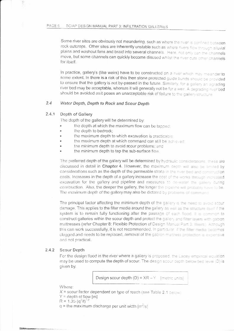
For the design flood in the river where a gallery is p'c:: s3: :-.may be used to mmpute the depth of scour. The des ; - s , : ," :
given by:
Wlrere:X = scour factor dependent on type of reach (see Tacle 2 '1
Y = depth of flo-w [mjR = 1.35 (q'/Í) ''Q = the maximum discharge per unit rruidth [m:is1
:i,\'een: uvial? n nels
: n nels
-:er to- _ ,,;ded----1i^^- ruÍrrg
-r hai,: UEU
I lJr.;
-tc,l Jfl
_::̂)c
- :'an
: afg
-:'on- -^,.1r:=u-- ng
.,u.
Design scour depth
BCIAP DESIGN N,'IANUAL PART 4 I NFI LTRATION GALLERIES PAGE 7
f = Lacey's silt factor
Table 2.1 Scour Factors
Ty[e of Reach I Mean Value ofL Scour Factor "X"
t.z3Qtrainht t LJv(' c.':r'
1.50ru,"o"rr,g qjó-,rn91|,-*,9rQ--- I -
Severe bend (also-!!enk ryo'pgliqn "1-.gyiq -l 175rQRigr,t ang,]ecllend (and p-ier noses and spulhelds)-- : a 00
Nose of Guide Banks i 2'25
For channels where the bed
calculated from the formula:material size is well known, the Lacey silt íactor (f) may be
í = 1.76 \'il
Where.D1,; = th€ sreve srze through which 50% of the material passes by weight [mm]
Alternativelv, the sili factor is given in Table 7.2 below for various sotl types'
Table 7.2 LaceY's Silt Factor
Lacey's Silt Factor "f"
20.0La rge boLt lders and__shi1g19
BoLrlders qd st!1919 __
Bor"rlders and gravel
Medir:m boulders, sh119!e and sand
Gravel and balrt
Giavel
Coarse balrr and sand
fiearvy sand
Frnr: balri and sand
ggillgg g::lnd
itlediLttl sarrd
Starrdai-d silt
l"4edittttr stlt
Frne stlt
\rery fitte stlt
Clay
Soil TYPe
15 0
.12 5
l0 0
on
4.7 5
275
2.0
1.75
1.5
125
1.0
085
0.6
0.4
50
rALrt ó BCIAP DESIGN MANUAL PART 3: INFILTRATION GALLERIES
2.5 Ownership of the SiteIn Balochistan, the ownership of any proposed site for an infiltration gallery weir and the landthrough which the pipelines and channels to the command area will pass, must be ctearlydefined and undisputed. lf the gallery site does not beiong to either the beneÍlting communÍtyor to the Government, problems are likely to arise. Even if the communrty vrho olvn the gagerysite and the beneficiaries are on good relations, the site owners rvill almosi cenainly use thesituation to try and derive some benefit to themselves. lf, on the other hand. the twocommunities have old rivalries, then it is most probable thrt the sjte ow,ners r.,rll try io preventthe galleryfrom being constructed.
2.6 Gallery Orientation, Guide-bunds and Cut-offsThe BMIADP Infiltration Gallery Design Manual prooosed tf.riee possibleorientations/combinations forgalleries. However, experience suggests 5et ca1:í,es are mostsuccessíul when used to tap (mainly) sub-surface flow, and should ex1e.t 1,, e: tne f ull widthof the rrver bed.
The reason forthis isthatthe composition of rivergravels c3n\.,êrr'cf,-s:;::: , a::css thewidth of a riverand consequently, sub-surface flows tend to be co::e.:-a:::: :--: :artrcularseams of coarser material. Successive floods passing down a r ,, ?r .,., ,r s _: _. :- _- .eclepositmaterial in the river bed and as a result, the paths along which mcs: c, :^3 sJ:-s,-ace waterflows can move from time to time. A gallerythat is only construciel a:-:ss ::t :,. ine riverrisks being left dry over time.
Galleries can be orientated perpendicular to river (ie direcily o,.e:angle. Straight across is cheaper, and galleries tapping sub-sun:::straight across. Galleries taping surface flow may need a longe: ,-.therefore be alrgned at an angle across the river (see Section 4 2
li tire river bed is particularlywide, and flood and sub-surface fil.,,- ---rr onr-) part, tlre-.n it nray be cost effective to Lluild a gallery in tl-rc i-: - :,,:protected guide bunds to ensure that the fiood fiows do not in tne ._:_--
_
AIso, cui-offs may be provided underthe guide bunds to preve-::^, s,passing the gallery These cut-offs may be concrete or a burjej r^TÊi-: j
cr at an: lrn nor{
-r 1l may
, . '-. ..irated
- --. l: SlOtl€
IrIITtrrtrIrIITTTIJ
il
3.1
BCIAP DESIGN I,'IANUAL PART 4: INFILTRATION GALLERIES PAGE 9
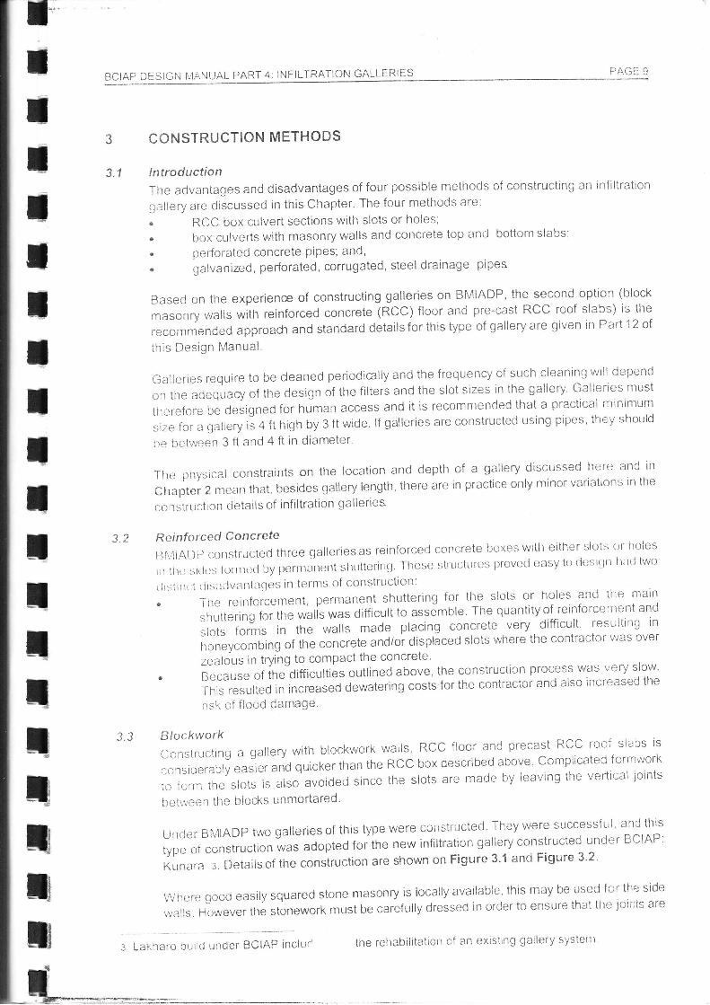
CONSTRUCTION METHODS
lntroductionThe aclvantages and disadvantages of four possible methods of constructing an infiltration
gallery are discussecl in this Chapter. The four methods are:
" RCC box culvert sections with slots or holes;
. box culverts with masonry walls and concrete top and bottom slabs;
. perforated concrete PiPes; and,r gálvanized, perforated, corrugated, steel drainage
Based on the experience of constructing galleries on BMIADP, the second
masonry r,valls with reinforced concrete (RCC) floor and pre-cast RCC roof
i"ecommended approaÓ and standard detailsfor ihis type oÍ gallery are given
this Design Manual.
Galleries require to be deaned periodically and the Írequency of such cleaning will depend
on the adequary of the c!esign of the filters and the slot stzes in the gallery' Galleries must
therefore be designed for human access and it is recommencied that a practical rninitnum
size for a gallery is 4 ft high by 3 ft wide' lf galleries are constructed using pipes' they should
lre between 3 ft and 4 Ít in diameter'
H'r --
option (blockslabs) is thein Parl 12 of
tlre plrysical constraints on the location and depth of
Chapter 2 mean that, besides gallery length' there are in
co nstruction cietails oÍ infiltration gailertes
Rc-inforcecj Concrete
Bf\liAUlr constructed three galleriesas reinforced concrete boxes with ettlrer slots
rrr llrg srtlgs lo1rtt;tj by pcrrrrlirlcttt shuttCrittg. Thcse structrtrcs llrovecl oasy to cigsitlrt
ilrslittr:i tlislttlvatltages in terms of constrtrctron:
. I lre reinforcement, pernranent shuttering for the slots or holes and the rnatn
shuttering for the walls was difficult to assómble. The quantityof reinforcenrent and
srors forms in the walli made placing concrete very difficuit' resulting in
honeycombing of the concrete and/or displaced slots wirere the contractoi'tr;as over
zealous in irying to compact the concrete'
. Because of ine oiniculties ouilined above, the construction process was very slolv'
Thrs resulted in increaseo dewatering costs for the contractot- and also increased the
trsk oÍ flcod tlamage'
3.3 Blockworkconstructrng a gallery with blockwork walls, RCC floor and precast RCC rooÍ slabs is
considerab|yeasrerandquickerthantheRCCboxdescribedabove.Comp|icatedformworktcf.;rtlthes|otsisalsoavoidedsincethes|otsaremadeby|eavingtheverlica|lointsL'etrveen the blod"s unmortared'
L;trderBN4|ADPtwogal|eriesofthistypewer.econsti"ucted.Theyweresuccessiu|.andthistype ot construction was adopteO toiine new inÍiltration gallery constructed unde r BCIAP:
Kunara:.DetailsoÍiheconstructionareshownonFigure3.landFigure3.2.
Wheregoocieasi|ysquaredstonemasonryis|oca||yavar|ab|e,thismaybeusedfortheside,"valls However the stonework must be carefully dressed in order to ensure that the joii"iis are
a gallery discussed here and tn
practice only minor variations in the
3.2 or nOles
Ir;rrl two
: Lakharo outltJ under BCIAP inclur' ' the rehabiiitation of an exisiing gallery systenr
:::ffififfië
PÁ3E ,i.BCIAP DESIGN MANUAL PART 3: INFILTRATION GALLERIES
of uniform size so that the filter does not migrate through the walls. The preferred altematrveis to construct the walls from precast concrete blocks. These should be made with a slighttaper on the sides so that any particle of the filter which passes through the front edge of theblocks continues to migrate through the rnell and does not become stuck in the walt. lf thisis not done, then the gallery slot would gradually become choked. The reinforcecj concretecast in-situ concrete floor slab and the lip of the roof slab are designed to prevent thewallsfrom being pushed inwards.
Perforated Concrete PípesA possible alternative to the box culvert approach could be using large (about 4 ft diameter)reinforced concrete pipes with slots cast into them. The pipes could be cast in short lengfisat site and then lowered into the excavation. This would be about the fastest possibleconstruction technique since almost no concrete work would be recu,red rn the river bed.lfthe pipes were about 4 inóes thick and made in three foot sections tren the'r,,,,culd weiohabout 0.45 tonneseach which could be easily handled on ste.
Galvanised Pertorated Corrugated Steel Drainage PipesGalvanised corrugated steel pipes have been used as culverts in n:any oaÍis of ihe Worldincluding Balochistan. The pipes are supplied in half sections, 2 ii rcrg arc ai-e boltedtogether on site to form a culvert. The sections are also eas)/ ir .ar:lie cr: siie as eachsection for a 5 ft diameter pipe only weighs abcut 180 lb The n',ar.ia:t;re's :í rnese pipescan also produce the pipes ready perforated with % inch hcies s3 t-3::r-e : :?s could beused to make an infiltration gallery. However, such pipes aí-e rii -anJ'3::Lie: rr Pakjstanand would therefore have to be inported.
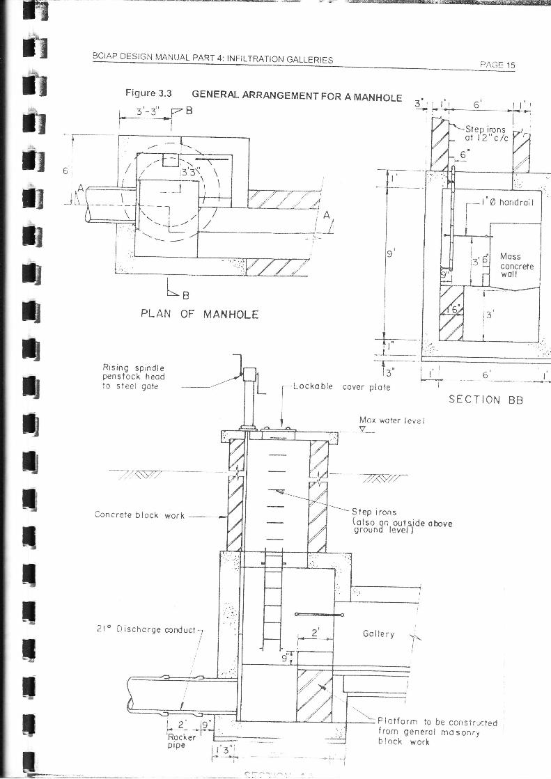
Gallery Access ManholeGalleries are likely to require periodic cleaning, hor.n,e'.'e''.',: :^=' :=-The gallery should therefore be provided with at least o:e :- ?- -' = ':
-
detailforsuch a manhoie is shown on Figure 3.3 lm::1:-i'=a:.-'=sinclude:
- Cesign
. The top of the manhole terminates above hr:. i::l ..=
. ïhe manhole is provided with a lockable cc', e' :r : -ê ,:^.
. The opening in the coverslab is large encu:-'-.' . -=^'-to be removeo;
. Good step irons or a steel ladder are pi'c\, ::l
. l\ small sump is provided to catch deols +:.'. ^lprpe; erncl
. ,\ gate is provided on the outlei to:ha J. -- :-.drained before starting in'oi-k oa a-a;.:2 - -; -
- ,
3.4
3.5
3.6
debris;debris
a r_ttt5 UtË
- L - ^ 1^ k^-t Sluuc
BCIAP DESIGN MANUAL PARÏ 4: INFILTRAÏIoN GALLËRIESf,tfrT
iIiiIttItIT
III
PAGE 11
3.7 Delivery pipeline ManholesManholes are required at intervals along the deliverypipeline to allow for inspecrron andcleaning/unblocking of the pipeline. For ease ofaccess to the pipeline, it recommended that themanholes be placed no more than 300 ft apart fromeach other. This is also the maximum practicalspacing for rodding the pipelines. The minimumdianreter of the pipeline itself should be 3 ft. This isrn order to allow a man to crawl down the pipelinei:nd clear any serious blockages _ normaliy the resultof roots entering the pipe.
Generally, the top of any manholes along thepipeline located in a river bed shoulci be above thedesign high fiood level. However, to reduce costs, apracticable alternative for a deep pipeline is for themanholes to be buried well below the river bed level.!n this case, markers need to be placed along theriver bank to show the location of the manholes.
2A
Laying RCC Delivery pipeline
The roof slabs should have lockable access covers. 'Rocker prpe sectrons slroulcj beprovrded either side of each manhole to facilitate differential settlenrent between the nianholeand the pipeline.
C an struction Seglrence and Dewateri ngTitil construction sequence ancj ttte method of cjewateringy the clallery exc:rvlitiitn arerfrlÍ)oi1aÍrt lor the successfr-rl and efficient construction of an infiltration aallery. Tlre trnring ofilrtllcrycxt--avattott is critical. in Balochistan, while Íloocls c.rnnotallvays be preclrctccl, withina iliven cltmatic region there are tirnes of the year when floods are likely and tinres when theyatenot. ExcavationforthegailerytrenchshouldbetimedtostaÍatthebeginninoof adryseast)rr; ttot one month into it. ïhis means that the contractor needs to rnobilise his rnaterialsancl equiprnent before the start of the dry season.
Sir,'rilarlywhere part of the galleryis to tre precast, then a sufficrent numberof units shoulcjire cast Lrefore excxvation is allowed to start.TltL: crltlstrrrctiort of a gallery is an exercise in trying to achier".e ntaximum proqress whiletitttlitlristtrt; risk. The risk of the excavation being clantilc;er11 [y:r floocl can be mirrirrisecj bv:
" l rrr.rely excavation;. Sf )cedy excavation; and. Parlial excavation.
Pailial excavation means excavating the gallery trench in sections, say 200 feet at a time. lfthe stte is therefore hit by a flood, only a portion of the excavation is damaged Where handlabour is being used to excavate the trench, this construction seqr,rence is easy. A sectionof trench can be dewatered and the gallery constructed whilst the next section of trench ist-'etng dug. When a section of gallery is completed it can be backfilled lvith filter ancl ordinarybackfiil whilst the next section oÍ gallery is being built, and so on. For a large gallery, fourgangs could therefore work simultaneously on precasting, exca'rating, galiery constructionand backfilling respectively.

-AUC tZ BCIAP DESIcN MANUAL pAryt 3: tNFtLTRAT|ON GALLERTES
where the excavation is to be undertaken by machine, the conrractor may prefer to excavatethe entire trench while he has the machine on site. In such cases, it is even more importantthat the contractor has sufficient labour and materials on site to allow the construction toproceed quickly within one season.
The main problem faced by a contractor in excavating for and constructing a galiery isgroundwater. In most cases, the gallery will be being constructed in 15 ft of higÀty permeableriver gravels and the excavation may be dewatered in one of three ways: pumping, gravtty ora combination of these.
When pumping is to be used, a number of portable diesel or, where available, etectriccentrifugalpumps will be required. The capacity of the pumps should be about aluat to themaximum discharge anticipated from the gallery. Additional standby purnps wrtn a combinedcapacity of between 25% and 50% of the maximum clischarge should alsc be available foruse. The pumps will have to operate continuously for several months and thev shouldtherefore be new at outset and reliable. A mmprehensive stock oí spare país should alsobe held on site and a good mechanic should be available at site. Care should atso be taKento divert surface flows well away from the gallery excavation so that infillrairon of this flowdoes not contribute to the flow having to be punped.
An alternativeto punrping may be a gravitytrench constructec Si:q1i1',, i1!e1;,1: iiran tlre fulldepth of the galleryexcavation. This trench is then lead down trle r,.e::er ei a shailo\^,erslope in the river bed, so that eventually the trench floor reacres ihe s,.l-ace For a 1Sftexcavation, in a river bed with a 1 in 100 slope (0.01)and assun rE i:re q;a.i\, trench has aslope of just 1:500 (0.002), then the tength ofthe trench wouic :e I B75t,i5 c 008)
Of course, the trench would have to be connected up to a sump ;r tne gal;e.. trench in orderto keep the working area around the gallery completely dry it rray ce cossi:le to recoversome or all of the cost of this trench if it can be taken along lre sarne aircnrnent as theproposed discharge pipeline. The trench would first be used for c3,,,,31Ê-irt ar c tnen as thepailially completed excavation for the discharge pipelrne
Where pumping is to be used for dewatering, a :ornoiiec .::..=:n .,, ii cravity flowdjversions can reduce pumping costs without the neeC 5r ols> :. ..':.. s:: e excavation.Shallowgroundwater may be intercepted by eXCê'rzi:: a s:: :... i:;-:- -:st-eam of thegallery trench and diverling the water away in lne sin .. -."=',,1 :-j.:. Cer,vaterinodescribed above.
BCIAP DESIGN il/ANUAL PART 4: INFILTRATION GALLERIESÊ
Ë
xIIItIItIIItIT
ttt
PAGE 13
Figure 3.1 GENERAL ARRANGEMENT FOR AGALLERY
CONCRETE BLOCK MASONRY
K. S" L.
Vories
Reinforced concrelelop slob seeFigure ll f or Detoil s =-\-
Veriicoi join?s - --I eft open
All joínts fullymortored -- _
Reinf orced concrete ----/bose slob onblinding layer
. LCoorse
f ilter,-- Medium f ilter
Finc Íiltor
-- ----T:',1v
1,,,, 1 -Vertical joints teft openJI J il-4'3'
3'{_ =*_*_ Ail joints fuily mortoredlf 1;*,_ _l_-f-.
i*
PAGÉ 14
-ï
BCIAP DESIGN MANUAL PAR- 3 INtrILTR,AT|OI'I GALLERIES
Figure 3.2 DETAILS FOR A CONCRETE BLOCK MASONRY GA-LERY
DETAI LS OF TOP SLAB
I f mer..l {scecf 3al rr:1 rdir
SeoxAef lo,r
PLAN SECTION
E LE VATION
' 7" -l "V;I I I tllÍË-mi nccl cf
I ll g:lie-; rcnnrL_ll__lt___
B" ,,,ti--]1li
aaa
aaa
a
oaa
aa
{-t"r ve'i,!i
IRK WA-X..SDETAIL OF
BCIAP DESIcN MANUAL pART 4: tNFtLTRATION GALLERTËSfíÊ
Ër
GilGl3
EË
E
E
tT
tIT
tttI
PAGE 15
Figure 3.3
i 3'-3" Vi-----lGENERAL ARRANGEMENT FOR A MANHOLË
B
PLAN OF MANHOLE
tolJIL
Rrsing spindlepenslock heodto steel gote
-l Kst--
concrele block wOrh --
2l o Dischcrge conductT
--r - *-lÍ
cover pl o le
l,,lLI-r, o IF --r:--.. --i
SECTION BB
L,
;-Locko bleI
I
I
t Mox woter levell,7
Slep irons(olso gr':. outqtde oboveground level )
Gollery
L P l^tí^.- .^uttvtttt iv
}!I
f--?- lL'Rocker' from generolb lock work
be consïrLftedmo sonry
Slep ironsot 12" c /c
f , , hondroii
\'./\1,/-1-\ \
-
ptpe
re-_
ft&&&frGfrftJu
GfrflG13
GfIfEt'lr?
BCIAP DESIGN MANUAL PART 4: INFILTRAÏION GALLËRIES PAGE 17
4 HYDRAULIC DESIGN
4.1 IntroductionBefore the hydraulics of the Ílow to the gallery can be considered both the surface and sub-surface flowavailability must have been determined, as must the physical characteristics ofthe river bed, as detailed in Part 1: Site Inve$iqations.
This Chapter discusses how to calculate the amount of available surface and/or sub-surfaceÍlow that may be captured by galleries of difíerent length, depth and slotted area. Only thesteady state solutions of flow to galleries are dealt with, that is where the inflow iscontinuously abstracted from the gallery by means of a gravity discharge pipe or continuouspumping. Unsteady flow conditions arise when pumps are used intermittenily to take waterfrom a gallery. This system is not practised in Balochistan and is therefore not drscussedhere.
4.2 Surface FlowsGalleries tapping surface flows are usually placed diagonally across the river bed. Thegalleries are surrounded by highly permeable graded filters which may extend to the river bedlevel (see Figure 4.1). However, this should be avoided if possible.
ïhe infiltration of the surface flow into the filter and rnto the gallery can be limitecj by any oneof three possible íactors:. the infiltration rate from the river tnto the filter laier:. the pernreability of the filter, and
' the flow into the slots of the gallery.
To design a galieryand filter, each of the above conditions must be checked, to determinewhrch is the limitino factor.
4.2.1 lnfiltrationRateFor a srrlple appr-oxirnation of the amount of inÍiltraiion, the infiltration rate nreasured on site(refer Part 'l: Site Investigatrons) should be multiplied by the area oÍ filter over which theperennial stream comes into contact. The area of contact is given by
WhereB
B
{)
= width of perennial stream
= width of filtei'at the surfaceangle of gallery to river bank 1= 90" for a gallery straight acÍoss the river).
lrr practice, 0 may vary from 900 to abourt 45c.
lf tlii: infiltrrltion r:rte of the natural river bedsurrounciing the gallery can be kept Lrelow therequired.
nrrterial is high enouglr the filter ntr:dia
scour level, and (gabicn) protection is not
bB / sin0
.gl
BCIAP DESIGN MANUAL PART 3: INFILTRAÏION GALLËRIES
4.2.2 FilterPermeabilityTo determine the second factor, ie the rate ofequationa may be used, where the symbols are
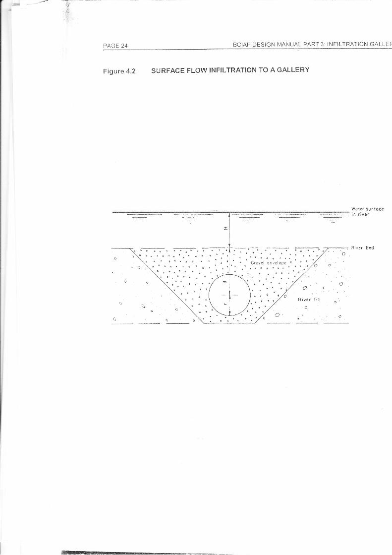
flow through the filtershown on Figure 4.2:
layer, the followng
l- = Qln(2dlr)2 xKH
Where:
4.2.4 MaintenanceGallenes tapping surface flow require regulator n:ali::-:- -:rate through the river bed material is not suÉíicte:l:., . j- :-galleryneedsto extend to river bed level !',rtn.a: --s:-:.away. These gabions are vulnerable to íic: j czra:: a-: -
yeafs. Once the gabions are damagei ::e'':=' -:l : .'. :nrecJia will become choked over tirne rel-'':r l::- ^t :-'
The length oíthat portion of the galleryover which the florv will pass [fr]The rate of discharge [ft'/s]The depth of the centre of the gallery below the river bed [ft]The radius of a circular galleryor the mean of half the depth and half thewidth of a rectangular gallery [ft]
K = The permeability of the filter layer which may be estimateC frcm the valuesgiven in Sedion 4.2of Part 1:Site InveSigations [fL,s]
H = The depth of flow over the gallery [ft]
Overtime, filter permeabilitywill reduce as the filter becomes choked r.,'iih erc'.^,1h of micro-organisms, and/or with smaller particles carried with the river flor^,,. Perioc c i-eplacement ofthe filter material is therefore required,
4.2.3 Slotted Area
As long as the gallery slotted area is in accordance ,,.,'iin ln: ::::-r^e^rr::rs grven in
Section 4.5, entry of flow into the gallery will not be a i,r: ^l': -':i a': :-: sudace flowintercepted bya gallerywill be thelowerof the fiiter per-:a: '. ?.^: r' :-3:r." rate valuesdiscussed above.
: ; the infiltration
-:r a around thet c:,ng lushedí: cí cnly a few
,-. so the filter
Substituting Equation 4.3 lnto Equation 4.4 gives
lrlrl._lrlrlrt_lrlrlrt
lrlrlrrttIIIIII&
4.3
BCIAP DESIcN [/ANUAL PART 4; INFtLTRAT|ON GALLERTES PAGE 1S
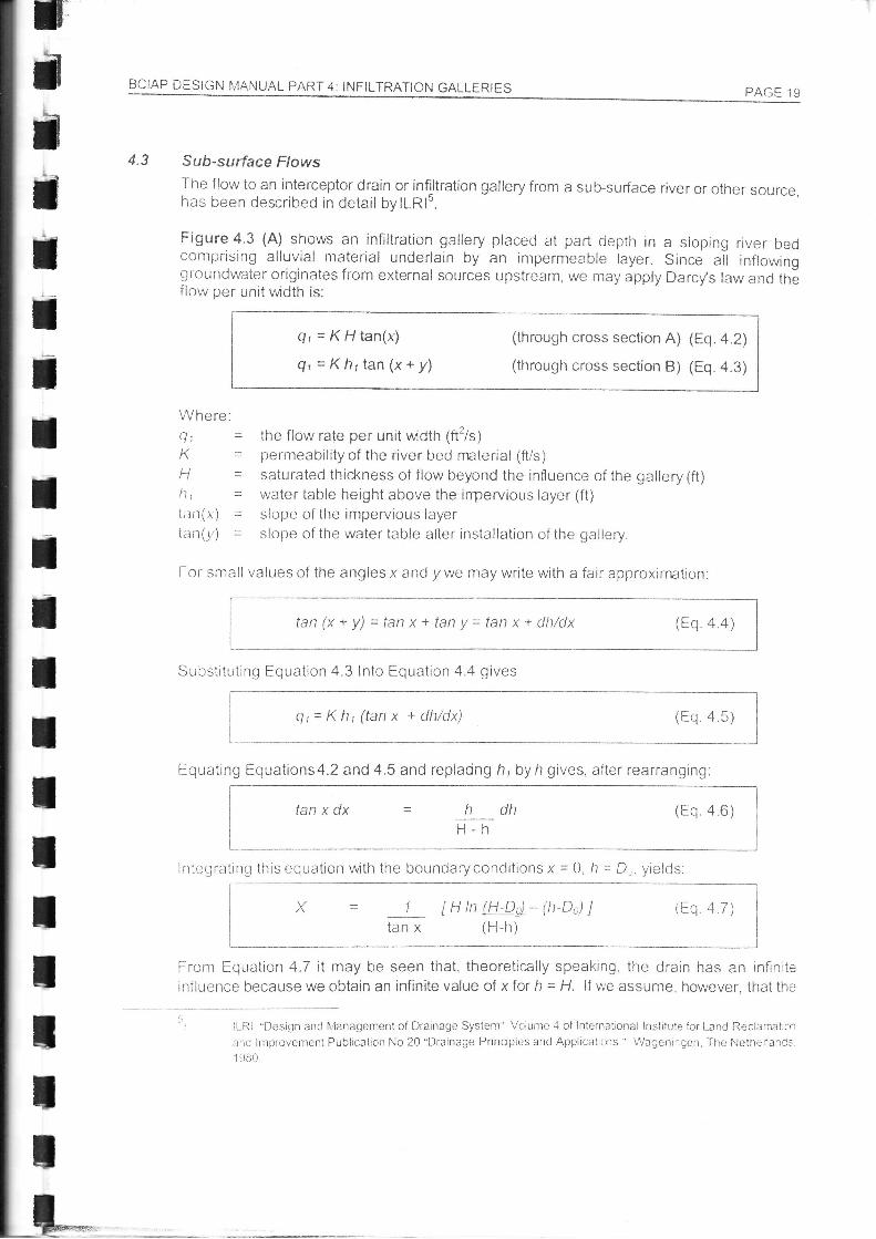
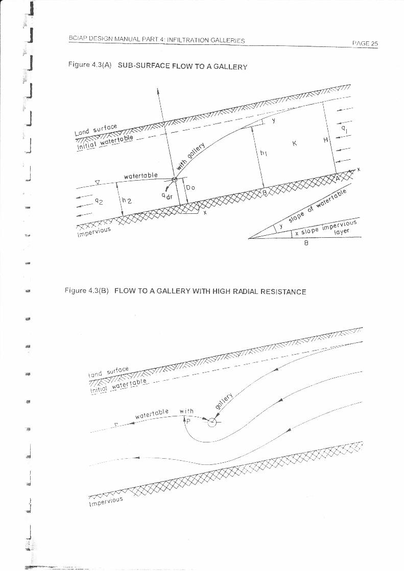
Sub-surface FlowsThe flow to an interceptor drain or infiltration gallery from a suFsurÍ'ace river or other source,has been described in detail bylLR15.
Figure 4.3 (A) shows an infiltration gallery placed at part ciepih in a stoping river bedcomprising alluvial materiai underlain by an impermeable !ayer. Since ail inflowinggroundwater originates írom external sources upstream, we may apply Darcy's law and theflow oer unit width is:
er=KHtan(x)
Qt=Khrtan(x+y)
(through cross section A) (Eq. a.2)
(through cross section B) (Ëq. a.3i
Where:Qt =K=t-j
h-:]|tim(.r) =t:ttr(121 =
the flow rate per unit width (ft'/s)permeabilityof the river bed material (ft/s)saturated thickness of flow beyond the influence of the gallery (ft)water table height above the inpervious layer (ft)slope of the inrpervious layerslope of the water table after installation of the gallery.
For sntall values of the angles x and )i we may write with a fair approxin"ration
Equating Equations4.2 and 4.5 and replaong hl by h gives, after rearranging:
lntegratirrg this equation with the boundaryconditions x = 0, h = D,. yields
|-1 tn lffQs)* (tt-Ds) l (Eq a7) I
tan x (H-h)
From Equation 4.7 it may be seen that, theoretically speaking, the drain has an inflniteinfluencebecauseweobtainaninfinitevalueof xforh=H. lf\À,,eassume.however.thatthe
It-Ri "Design and lvlanagement of Drainage Systenr" Voiume .{ of Internatjonal lnsiitule for Lancl Reclarnatrc'r
and lrilproverÏent Publication No 20 "Drainage Prinoples ancl Applicatrc,:s.' Wagenir';en, The NethríanCs.1 980
tart (x + y) = tan x + tan y = tan x + dlt/dx (trn 4 4\
Qr=Kh1(tanx +dlt/dx) (Eq a s)
tan x dx dh (Eq a 6)H-h
PAGE 20 BCIAP DESIcN MANUAL pART 3: tNFtLTRAT|ON GALLERTES
distance corresponding to h =0.9H to be the efective distance overvrhjch the drain exertsa significant drawdown, we can write, takinq Dn= à 11..
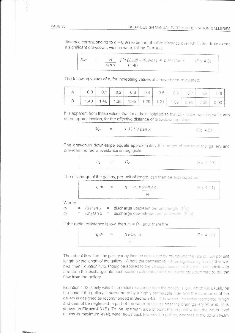
Xerr = H Un (1 - a)-(O.g-a) I = b t1 i'(ian x; tiq .t.B)tan x (H-h)
The following values of b, for increasing values of a have been cal:u:ate,j
It is apparent from these values that for a drain installed so t-3i .-::some approximation, for the effective distance of dra',^;oc,,,,- ,:-s
Xrrr 1.33H/(tanx)
The drawdown down-slope equals approximately ire *?provided the radial resistance is negligible:
:-e callery and
Itz - Do l r,1 \
The discharge of the gallery, per unit of length, can !he- t3 !,t-:$::
qdr = q,-Qz=(H-h)q tl
t-l
Where.q. = KH lan x = discharge upstream a?' --' =- l'- ..t =
Q: = Khzïan x = discharge downstr-ea: :-' -' '. .,,' ," :- _-
l{ the radial resistance is low, then h2 = D;, êlc r::.:r':
q dr = (H-Do) q,
LJtl
< _ 5'-
The rate oí flow from the gallery may then be cal:- ::: I :length by the length of the gallery. \A/here the ce'-:-: :.
hprl then Forratinn 4 12 shor rld he aonlrpri i::re .:'t-sand then the discharge into each sectior ceicu'a::: :^:flow from the gailery.
Equation 4.12is only valid if the radial resisiar:e r-:- l^; := =the case if the gallery is surrounded by a h,g:i; c.-i'-ei: =' :
galleryisdesignedasrecommendedinsection 4.5. ,: l^:.,.e,.-'.^. -a:a -:srsianceishighand cannot be neglected, a part of the water passi:c -::e':-e :-a - ;a ::j reiurns, as isshown on Figure 4.3 (B). To the upstream side oí pornt P i-3 t- .l ;.,-Êii:ne',vater lr:velattains its maximum level), waterflows back to,,rrlr-cs the galierr. ,,,::reas t-_:le cjoi,;nstrr:am
A 0.0 0.1 0.2 U.J 0.4 0.5 cC :7 ,-Sl 0.9
B I A^t.+u 1.40 1.38 1.35 t.zY 121
táfrr
II
4.4
ECIAP DËSIGN tuJANUAL pARï 4: tNFILTRATION GALLERTES PAGE 21
side it flows down-slope. Equations 4.9 and 4.10 above are equally valid, provicjecl that h2 isgreater than Do. lf the radial resistance has to be taken ínto account, computer models arerequired to determine the shape of the water table.
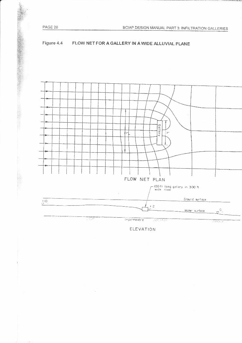
The above two-dimensional theory applies well to a gallery in a restricted river bed, such aswhere the river is passing through a rock gorge and is confined on both sides. Where a riverts sttuated in a wide alluvial plain then flow may well be passing th|ough the alluvial materialon both sides of the river as well as in the river bed itself. Where the site investigations showthls to be the case, an approximation as to the amount acicJitional flow the gallery may colect,clue to the edge effects, may be determined try plotting a flow net in plan of the flow to thecallery' as shown on Figure 4.4. This type of flour net is cJifficult to plot manually trut isamerrable to computer solutions, On Figure 4.4, the flow net shows that the effective lengthof the galleryoÍ length L is L', ancl it is the length L'which should be used in computrncl theflow from the gallery in the above equations
Surface and Sub-su rtace FlowsSome galleries will be designed to tap both surface and subsurface flows. lVhere this is thecase then the hydraulics of flow through the filter may be undertaken inclependenfly and thenthe two flours added together to get the total flow Írom the gallery. This is a satisfactoryapproxtmation, since the flows take place in different areas of the filter. However, whencalculating the area of slots required to be placed in the gallery, the combinect surface andsub-sr-rrface Ílows must be used.
S/oÍ LocaÍion and Slotted AreaThe location of the slots in a gallery and the open area to be provided wrll depenci on therequired rate of flow into the gallery, the orientation of the gallery, how the flol; will enter thegallery, allowances for the flow in the gallery to pass along the gallery, and the structuralrntegrity of the gallery.
In orile r to cnsure that the entry losses into tlre gallery arr: small. it is reconrnrcnrlorj" that thecttit'ittrttc ve locity into tlre slots is liiliteci to a nraxinrurl of 0. I fl'sec;. lt is ÍLrrlhr;r suggestedtirat thts t,elocity should be achieved with 509i, of the area of the slots blockec.l. The wirJth oftlte siots should be a maximum of 1 inch and should correspond with the design of thetrtriernrost layer of the filter material so that the Íilter rnaterial cannot migrate into the dots.
When designing the layout of the slots, the structural integrity of the gallery must be taken iirto:tccount. ln order to achieve this, the open area oÍ the slot may not exceed 69ó of the area ofthc walls of the gallery. Where the 6% limit nreans tlrat gallery cannot accept the vrholedo'sign flcw as calculated in Section 4.2 andlor Section 4.3 whilst maintainrng recomrnendedritaxirlrrn.r entranc;e velocities. then tlre ctallervmust be lenothened.
\\ltt-'re a g;tllery lras Lreen assunred to irave low racial resistance. then all the slots requÍrecJto :rccunrnrodate thi: design flow must be nraCe in the upstream face of the qallery It nrayircr,^,rever strll be worth placing some slots in the dor,vnstream wall though these wili, in iheory,only cotre into operation should the upstream filter and slots become blocked The loyrer part
of t..oth srde r.n;atlls should be left unslotted, in order to fornr a channel inside ihe gallery Ír_.rr tiief lovr to pass along the gallery to the discharge point. lf a gallery is being designcil to tapsurface flows, then the slots may be provided in the roof oÍ the galleryas r,^;ell as the sides.
4.5
r|Tr|r|rlt; T!V "The Desrg;n a;-'' ionstÍuclron of InÍltralr:n Gelleries." Groundlroter V1, 3 No '_j 111(t

PAGE 22 BCIAP DESIGN MANUAL PARï 3: tNFtLTRAT|ON GALLERIES
4.6 O utlet P i pel i ne/Cond u itAs discussed in Section 3.7, the minimum size of the pipeline should be set accorcting to therequirements for maintenance and repair of the pipeline. However, the hydraulic capacity ofthe pipeline should also be checked. ldeally, this should be done using the Coiebrook-WhiteequationT. Manning's equation may be used but only if the designer is confident that thepipeline will not be running full.
Given the inaccuracies of the methods of determining the sub-surface flows and theanticipated flow from a gallery, it is recommended that the discharge system be designed for25% greater than the anticipated maximum flow from the gallery. This will not significanlyincrease the cost of the system but will allow for the scheme to take advantage of higher thananticipated flows.
I
I
It
I
tIIII
HR Ltd 'Tables br the rlpra.rc Des4n oÍctunneis and pipes.' Htsraulics Research Ltc. uK
BCIAP DESIGN MANUAL PART 4: INFILTRATION GALLERIES PAGE 23
il
T
tI
Figure 4.1 cRoss sEcïoN THRoucH A GALLERY rApplNG suRFACE FLow
.l:1
IIT
IIil
tIIT
I
Gobion pÍotection lo íilteÍ loyers
fA\rt Z+ BCIAP DESIGN MANUAL PART 3: INFILTRATION GALLEF
Figure 4.2 SURFACE FLOW TNFILTRATION TO A GALLERY
Woler sur íoce: In rlveí
River bed
BCIAP DESIGN MANUAL PART 4: INFILTRATION GALLERIES r-l\L)tr zJ
Figure 4.3(A) SUB-SURFACE FLOW TO A GALLERY
ffi -
"9woterto ble
1- o,
ràóututou'
Figure 4.3(B) FLow ro A GALLERY wlrH HlcH RADIAL RESTSTANCE
E
I*I
Id
.l'I
J
I
J;,I :!;
íá,*lutot:- -
',r6terlolfw rÍn
|'
I\ont-t
srrrÍoce
iá'tiot
/^'- - -__.----
-11/
--_7
,/*#at'"
iáptt'iou'
F** .-:--:__.*
PAGE 26 BCIAP DESIcN MANUAL PARï 3: tNFtLTRAT|ON GALLERTES
Figure 4.4 FLOW NET FOR AGALLERY IN AWIDE ALLUVIAL PLANE
FLOW NET PLAN
/-lOO.ít long gollery rn 3OO fr/ wtoe rrver
Ground suríoce
ELEVAÏION
5.1
5.2
BCIAP DESIGN MANUAL PARï 4: INFILTRATION GALLERIES PAGE 27
5.3
FILTER DESIGN
General
Galleries must be surrounded by a graded filter; usually comprising several layers. The filtersare designed to provide a highly permeable surround to the galiery, to ensure minimumhydraulic resistance for the flow entering the gallery and to prevent material from the river bedmigrating tourards and entering the gallery
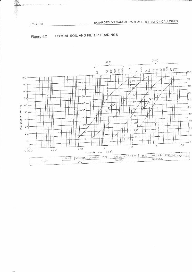
Gallery Tapping Sub-surtace FLowFor a gallery tapping subsurface flow, the pattern of the filter layers is usually as shown onFigure 5.1. The finest layer of the filter is placed outermost and the coarsest innermost, iethe permeability increases inwards. The gradation of the íilter layer or layers forming theinveded filter should conform to the following rule, established originallybyTerzarghi:
d15 filter i d65 soil < 5;d,5 filter / d15 soil > 5; andd5e filter / dso soil < 25
Where ds5 is the sieve size which will pass 85% of the material, and similar for otnerpercentages (d15 and d5s).
The above criteria relate respectivelyto:. stability (ie preventing the nnvement of soil parlides into the fitter):. permeability and,. uniformity.
Wltt:rt plottecl on a clrading graph, as shown on Figr.rre 5.2, the grading curve of the filtersho'.rld be sensibly parallelto that of the underllng soil. The filter should also contain lesstirair 5% of niaterial that wll pass the number 200 sieve (0.074 mm).
For the inner Iayers of the filter, the layer should be designed using the above criteria, butsubstituting the grading of the outer filter for that of the "soil'. For the innermost layer, thegrading must also be coarse enough to prevent material passing into the slots of the gallery,to ensure this, the followrnq rules should be adhered to:
rJ,,,, filter / slot width > 2tl,, filter should bre qreater than the dot size.
Tlre nrinirrurn thickness of each filter layer should be 10 inóes.
Gallery Tapping Sur-face FlowGalieries tapping suíace flow are vulnerable to the filters being scoured a',vay, and shouldbe avoided if possible. Houever, if a galleryis designed to tap surÍace flovr, the filter layers
stroiild usually reach up to the river bed, as shown on Figure 4.1. The filter is protected er'iher
by gabion mattesses or stone riprap or concrete biccks.
USBR recommends the following formula for detennining the size of riyrap that wBXLt beclislodqed under turbulent low conditions:
USBR 'Hydraulic Design oí Stilling Baslns and Energy Dissipators" United States Bri'eau of Reclarr;,.,oni ss3I
IJ
a
PAGE 28 BCIAP DESIGN MANUAL PART 3 INFILTRATION GALLERIES
Where:v avnu50
Dso = (V.u | 4.91q? (turbulent flow conditions) [metric unitsl
average velocity of flow for maximum discharge [m/s]average stone size [mj
The specific gravity of the stones was assumed to be 2.65 (ie density of 2,650kg/m.;. lí lessdense stone is used, then the stone size should'be increased correspondingly.
The grading of the rip rap should be as follows:. Maximum stone size = 1.SDso. Minimum stone size = 0.5Dso. Not more than 40o/o ol the stone should be smaller in size than D5o
The thickness of the rip-rap layershould be at least 1.5 timesthe-stone D5s size.
lÍ uniform sized concrete blocks, which have a specific gravity of 2.2, are used, then theweight of each concrete block should be at least 1.5 times the weight (about 1.8 times thestze) of the Dso size rip-rap stone. A lifting "eye" should be incorporated in each block duringpre-casting to facilitate lifting and placing.
PAGE 29
BCIAP DESIGN t4ANt,'4L PART 4: INFILTRATION GALLERIES
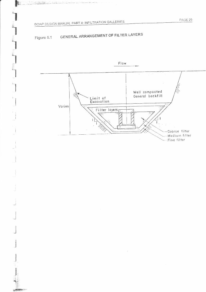
Figure 5.1 GENERAL ARRANGEMENT OF FILTER LAYERS
i{j
IIJ
III
Ia
I:J
II
Ja
IIIJ
, +j '".q;!*i-3ri5
#'
BCIAP DESIGN MANUAL PART 3 INFILTRATION GALLERI ËSPAGE 30
Figure 5.2 TYPICAL SOIL AND FILTER GRADINGS
Pn{mn}
9: RfrÈ 33Ëgia
tmm./
\ó |.'mNdln
roo
90
AN
70
>v
t-"IIll0I
lI
i..1 ic
I
1I
-l
€
0
óo
<n
d0
JU
r0
o
drtlCle!
:oÀRS: I F tN: Ir"':l uM lLU"F(5È ..,-\RÊ :veDruN't I co,rnse rIi:: ll,taorut,t
CLAYF I f.]E SAND I
SI LT
qïn
%
%
3%
3%
3%
h'13
\.Yr-
3
6.1
BCIAP DESIGN MANUAL PART 4: INFILTRATION GALLERIES PAGE 31
6.2
STRUCTURAL DESIGN
GeneralThe loadings and sti'uctural design for a gallery constructed of masonry walls with reinforcedconcrete floor and roof slabs are discussed in this Chapter. An example of the structuralcaiculations are given in the worked example in Appendix A. The design of other types ofgallery, particularlyfor a reinforced concrete box culvert type gallery, would be verysimilar.The design of a reinforced concrete pipe type culvert is not covered here, vfiilst the desiqnof a galvanired steel pipe type galleryis covered !n the nranufacturer's literature.
The final part of this Chapter discussed the bedding details required for the outlet pipes fromthe galleries.
RoofIt has been found that the worst case loading conditions íor a gallery are when the gallery isunder its maximum design flood, taken as a 1 in 50 year flood event in this fvlanual. ïhe depthof water above the bed level íor a 1 in 50 vear flood will Íirst therefore have to be determined.
The forces on the gallery are shown on Figure 6.1. The vertical forces on the galiery top slabcomprise three components:
The water pressure (p*)on the slab due to the depth of water above llre siab:
Puu=hz;r*g ltrtlm2]
Where:
I'Wh-I Ii
n=:JÀl^r^.I \UTU -
density of water [1 ,000kg/m')height from top of flood water level to the roof of the gallery [m]gravitational oonstant [9.8t n/sz]
1 kg exerts a force of 9.81 N.
3T?\
3%-r
ii The submerged weight of soil (p,) which is due to the weight of soil less the
hydrostatic uPlift:
p, = /i, 1r'g [N/mz]Where:
p' = submerged density of the soil (p, - p*) [kg/m3]ltr = depth from river bed level to the galleryroof [m]
iii. The self weight of the roof slab (p,. ):
p,=ip-g tN]
Where:pc = unit weight of concrete [about 2,400 tg'mt]f - the thickness of the roof slab [ml
The pi-essures are converted to forces per unit length of gallery by multiplyrng by the widïh of
the gallery roof slab. The total load on the roof slab is then the sum of the above three forces.
Usually this force is multinlied by a load factor of around 1 .4 as a factcr oí safety.
BCIAP DESIGN MANUAL pART 3: tNFtLTRATION GALLERTES
The roof slab is considered to be simply supported on the side walls. The vertical ioad actingfrom the rooÍto the walls and vice versa is half the total load on the roofslab on each wall.
The rooí slatl inay now be designed according to conventionalreinforced concrete desionpractice. j
WallsThe lateral forces acting on the walls are greatest at the base of the walls, and are shown onFigure 6.1. These lateralforces comprise three components:
i. Hydrostatic pressure at bed level = hc Í\u g Jtrt/mz]
Where:pw = density of water [1,000kg/m3)g = gravitational onstant [9.81 nvs2jh4 = heightofwaterabove bed level during dedgn flood [m]
rAtrtr Jl
6.3
ii. EÍfective earth pressure = Ko fu g' g
Where:
Loose sandShale fillingRock fiiling
Iw/m2]
= coefficient of static pressure = 1 - sin O
= submerged density of the soil (p. - p*) [kg/m3]= depth of soil to base of gallery from the river bed [m]= shear strength of the soils.
For cohesionless soils, O mav be taken as:
Sandy gravel 35" to 40'Comoacted sand 35'to 40"
Ko
p'
O3
O
30" to 35"30'to 35"35" to 45"
Additional hydraulic pressure = h:[1" g [N/mZ]
Where:
tlw = density of water [1,000kg/m3)/r: = depth from river bed level to bae of gallery [m]
f lre total lateral clesign pressure acting at the base of the walls is the sum oí the above threepressures, rnultiplied by the load factor of 1.4. The walls are also subjected to vertrcal loadson the top and bottomfrom the roof slab and the floor slab respectively. Tnese loads tendto prestress the walls.
The mclde of structural failure of the walls is most likely to be in shear resulting from thelateral forces. Therefore an allowable characteristic shear strength needs lo be calculatedand conrpared with the shear resulting from the design ccnditons. From this, the optimumblock size is found.
BCIAP DESIGN MANUAL PART 4: INFILTRATION GALLERIESPAGE 33
Allowable Shear StressBS 5628:Part1 Chapter 25e
f,,=51 +0.6Gu
In metric units,f" = 36,000 + 0.6Gu [kg/m2]
deínes the characteristic shear strength, fu, of masonry as:
flb/inch2l
G,Pí
design vertical load per unit area of cross-section q= p I tw) [kg/mz]the vertical reaction of the wall against the floor slab [kg]the thickness of the wall [m]
The allowable shear stress = f,I 2.5
Where 2.5 is a paftial safety factor for masonry strength in shear. When considerinq theiikelihood of misuse or accident the value nray be reduced to 1.2S.
Actual Shear StresThe actual shear stress for the design conditions is thenof gallery
Shear force (F) = pressure at base of wall . H | 2
and
Shear stress = F I (t,") [N/mz]
V/here.= shear force [N/m length of gallery]
= height of the wall [m]= thickness of the wall [m]
lf the-. actual shear stress exceeds the allouable shear stress then the thickness of the wallt., should be increased.
ln the desigrn of the masonry gallery shown on Figure 6.2, the shear at the junction betweenthe walls and the rooÍ and floor slabs is also resisted by the downstand Írom the roof slab andthe insitu concrete channel insed in the base slab.
FHt,,
calculated as follows per unit length
[N/m length of gallery]
BS 5628 "Code of Practice forStandards Institute.I
fI
*4otl=;.
S**hc*r&r-'r
Use of Masonry Part 1: Structural Use oÍ UnreinÍorced lvlasonry,, gntish
PAGE 34 BCIAP DESIGN MANUAL PART 3: INFILTRATIoN GALLERIES
6.4 FloorThe vertical forces on the floor slab comprise two components:
i. The uplift water pressure on the slab.
P* = (ht + hd) p* g [N/m2]
Where:
Pw=hs+ht-
Compact gravel or sand wellcemented
Compact gravel or sand andgravel
Loose coarse sand
Loose fine sand
density of water [1,000kg/m3)height from top of flood water level to base of floor [m]
ii. The verticalforces transmitted from each wall:
F = N +w [N perm length of galtery]
Where:N = vedical load on eaó wall from the roof [N per m length of galleryJw = weight of one wall [N per m length of galtery]
Next the bearing pressure needs to be calculated to see if it exceeds the allowable bearingcapacity of the gallery foundation. The following equation assumes that the íorce F soreadsout to cover the whole of the base.
Bearing pressure = 2F | il - p* IN/m21
Where:vertical force on íloor from one wall [N per m length of gallery]uplitt water pressure on floor [N/m?lwidth of base slab [m]
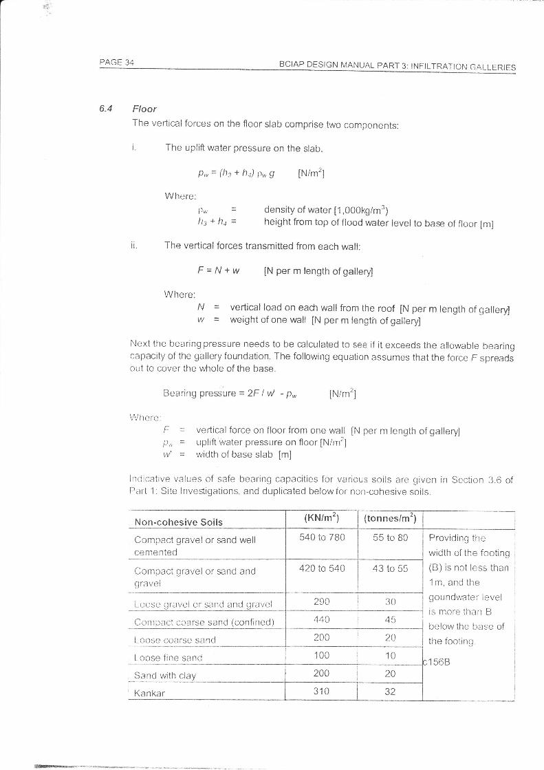
Ittcjicative values of safe bearing capacities for various soils are given in Section 3.6 ofPa11 'l: Site Investigations, and duplicated belowfor non-cohesive soils.
Non-cohesive Soils
Loose qravel or sand and gravel
Providing the
width of the footing
(B) is not less than
1m, and the
goundwater level
is more than B
below the base of
ihe footing.
I corJ
cotttPact coarse sand (confined)
Sand with clay
tr
/l=
vv
{tonnes/m')
540 to 780
420 to 540 I 43 to 55
Kankar
440
1-1
I SCIAP DESIcN MANUAL pART 4: tNF|LTRAïION GALLERTES
,l
PAGE 35
lloleê:l The values given in the table are only approximate, and the allowable bealng pressure forindividual soils may differ considerably. The figures have a íactor of safety of 2 to 3.2 lf the groundwater level in sand or gravel soils is likely to approach foundatir:n level rhe safe
beanng capacity should be reduced to about one-half of the values given.3 The safe bearing capacity can be exceeded where the foundation is taken well down Into theground by an amount equal to the weight of the material which is displaced by the fountJation
itself .
Outlet GateThe gate on the outlet of an infiltration gallery will typically be a slide gate with a screw hoistfor opening and closing it from the manhole roof. The screw hoist is required for closing srncetlre gate is so small that it cannot be guaranteed to fully close under its own weight. Thebasic principles for design of the gate itself are the same as those described in Chápter 7 ofPart.2. Weir Design.
Outlet Pipe BeddirtgThe load bearing capacity of a concrete pipeline is dependent both on the strength oÍ themanufactured pipe and on the support provided by the bedding. For most pipes, buried 3ftor 4 ft below the ground level, the bedding conditions of the pipe are often not critrcat.llowever, the discharge pipe from a gallery is often buried at considerable depth and thebedding detail br the pipe must therefore be considered.
The bedding factor F,,, is a numeric description of the degree of support provided by differenttypes of pipe bedding. The higher the bedding factor, the greater is the load-carrying capacityof a grven pipeline. The types of bedding normally used with concrete pipes are shown onFigure 6.3. The three most common bedding types are:
Bedding FactorClass B ('180 degreesgranular bedding) 1.9Class S (360 degreesgranular bedding and s_rrround) 2.2Class A (plain mncrete cradle) 2.6
Figure 6.4 gives the appropriate class of beddíng to be adopted for class ltyl pipes burbd atdtfferent depths. The table has been developed using criteria deveioped by BRE10 and shouldcnly be under the following conditions:. for concrete pipes equivalent or $ronger than Class M,. \l/here the densityoÍ backfill is less than orequal to 125lbltj; and,. whêre traffic load on the trenó rs very light, as appropriate to field conditions.
6.5
6.6
!r
tJRE "Srrttplified Tábies of Fxternal Loads on Buried Pipelines' Buildrng Research Ëstablishíïent. UK
PAGE 36 BCIAP DESIGN MANUAL PART 3: INFIITRATION GALLERTES
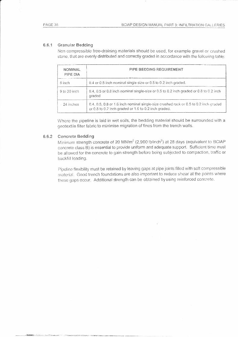
6.6.1 Granular BeddingNon compressible free-draining materials should be used, for example gravel or crushedstone, that are evenly distributed and correctly graded in accordance with the following table:
NOMINALPIPE DIA
PIPE BEDDING REOUIREMENT
6 inch 0.4 or 0.5 inch nominal single size or 0.5 to 0.2 inch graded.
9 to 20 inch 0.4, 0.5 or 0.8 inch nominal single-size or 0.5 to 0.2 inch graded or 0.8 to 0.2 inchgraded
, 24 inches 0.4, 0.5, 0.8 or 1.6 inch nominal single-size crushed rock or 0.5 to 0.2 inch graded
or 0.8 to 0.2 inch graded or 1.6 to 0.2 inch graded.
Where the pipeline is laid in wet soils, the bedding material should be surrounded with a
geotextile Ílter fabric to minimise migration of fines from the trench walls.
6.6.2 Concrete BeddingMinimum strength concrete of 20 MN/m2 1Z,SOO lb/inch2) at 28 days (equivalent to BCIAP
concrete class B) is essential to provide uniform and adequate support. Sufficient time must
be allowed for the concrete to gain strength before being subjected to compaction, traffic or
backfill loading.
Pipeline flexibility must be retained by leaving gaps at pipe joints filled with soít compressible
rnaterial. Goocl trench foundations are also irnportant to reduce shear at the points where
these gaps occur. Additional $rength can be obtained byusing reinforced concrete.
_---Ésr@/
-TALLERIES
PAGE 37
Figure 6.1 LOADTNGS ON GALLERY
.l
/III
w
/I
I/4
Ilitl
%%%333}
ru
35fr%
%
River bed level
PAGE 3B BCIAP DËSIGN MANUAL PART 3: INFILTRATIoN GALLERIES
Figure 6.2 TYPICAL GALLERY CROSS-SECïON
Reinforced concretetoo slob seeFióure ll f or Detoils
r 5' Il*--- r fiI r-'"1
Verticol joints left oPen
All' joints tullY morforedVerticol joinisleft open
All ioint6 fullYmortored
Rei nforced concretebose. slob onblindi::c layer
loss B
---T_.l3
BCIAP DFSIGN MANUAL pART 4; tNFtLTRAT|ON GALLERTËSJr!Fl 'r
Jfi
J
JIII
IJ
II
J
I
I€t
J
II,
#
Ji
JI
J
td
ïc
J
J
J
PAGE 39
Figure 6.3 BEDDING DETATLS AND FACTORS
GRANUI-AR BIDDING
12"(J00rnm)
Closs Bi80 Gronulor BedFm - 1.9
CONCRfTI BTDDING
ïr",r00,',-,
Bc
;
II
t
f:: j-too:-) m;n I
1 U4 B;._nl^-^
^vr\-,t')è /1
120 Concrete CrodlePicin Concrete Fm - 2.6
Closs SJ60 Granulor Bed onCFm - 2.2
-TtJ i re"{roomm)
II
I
8c
r_tY-ï"
roundSur
-ï-Granuior Beddïng Moteriol T--t
Selec'.ed Bockfiil Materiol FFri
ln-si|.u Concr*te Í:r l
Notes:
] Bedding beneoth cnd of sides of pipe to be well compocted.2- Beddinglbockfiil direcily obove the pipe to be tightry ;;;;rcted byhond.J J. Dimensio n y:1/ 68., .ï j: \ '0mm)under , --ers, ond 2,,(s0mm)j minir-nw*.r ,*,rtlér sockets wi,, _ ' "
H::""'Ï;";:,iiá,:r,,:..'l,*;,,l,"Í:i','1;*;{;:;í1fflïË;iào*]ry*j
PAGE 40 BCIAP DESIGN I/ANUAL PART 3 INFILTRAÏION GALLERIES
Figure 6.4 CHART OF PIPE BEDDING IN REI-ATION TO DEPTH
ct-uco
g)tJ)0c
ffi
ctl.;
co
aQ
o
tltltltltltl
€a)
LLI
g
oq
ó
ffi

.iri,.Ïï.'r-', .:r.:n.ï".r
,' t.,.;r,
APPENDIX A
WORKFD EXANIPLE
BIBLIOGRAPHY
Bennett, TW
Bouwer, H
British Statnciards Institute
Building Research Establishment
Hanson,G&Nilson,A
HRL
Huisman, L
ILRI
Kruiseman, GP & de Ridder, NA
Ncil Cll
T]SBR
USBR
US Departrrrcnt of the Interior
Withers,B&Vipond,S
"The Design and construction of Infirtration Gaileries.,,Groundwater, Vol 8., No. 3, 1g70.
"Groundwater Hydrorogy" McGraw-Hiil Book companv. 1g78.
BS 5628, 'Cocle Of practice For Use Of íVl;isonry, part 1 ,
Structural Use of Unreinforced fvlasonry.
"Simplified Tables of External Loads on Buried pipelines.,,BRE, UK
"Ground Water Dams for Rural Water Supplies in DevelopingCountries." Ground Water Magazine, July-August 1986
"Tables for the Hydraulic Design of Channels and pioes.,,Hydraulics Research Ltd, UK.
"Groundwater Recovery.', Macmilla n, 1g72.
"Drainage Principles and Applicatron, Volume 4: Design andManagement of Drainage Systems.,, International LandReclamation lnstitute, Wageningen, The Netherlands. 1 gB0.
"Analysis and Evaluation of pumping Test Data." InternationalInstitute íor Land Reclamation, Wageningen, theNetherlands. 1979.
"Guide to Bridgc Hydraulicl;.", Unlversrty of l'oronto press.1 973.
"Design of Srnall Dams." Unite<j States Bureau ofReclamation. 1977.
"Hydraulic Design of Stilling Basins and Energy Disipators.,United States Bureau of Reclamation. 1g83.
"Groundwater Matnual.' 1 981.
'irrigation Design and Pradice. BT Batsford Ltd, i974.