Embed Size (px)
Citation preview
BC87Q Intel® Q87 with Core™ i7/ i5 /i3 ATX Motherboard
User’s Manual
Ver. 1.1
BC87Q User’s Manual
2 BC87Q User’s Manual
1.1 Product highlights .....................................................................................................14
1.2 Before you Proceed ...................................................................................................16
1.3 Motherboard Overview ..............................................................................................17
1.3.1 Placement Direction.......................................................................................................17
1.3.2 Screw Holes ...................................................................................................................17
1.3.3 Motherboard Layout.......................................................................................................18
1.3.4 Layout Content List ........................................................................................................18
1.4 Central Processing Unit (CPU) .................................................................................20
1.4.1 Installing the CPU ..........................................................................................................21
1.4.2 Installing the CPU Heatsink and Fan.............................................................................23
1.5 System Memory..........................................................................................................26
1.5.1 Overview ........................................................................................................................26
1.5.2 Memory Configurations..................................................................................................27
1.5.3 Installing a DDR3 DIMM ................................................................................................27
1.5.4 Removing a DIMM .........................................................................................................29
1.6 Expansion Card ..........................................................................................................29
1.6.1 Installing an Expansion Card .........................................................................................30
1.6.2 Configuring an Expansion Card.....................................................................................30
1.6.2.1 PCI Express x16 slot...................................................................................................30
1.6.2.2 PCI Express x 4 slot....................................................................................................30
1.6.2.3 PCI Express x 1 slot....................................................................................................31
1.6.2.4 PCI slot........................................................................................................................31
1.7 Jumpers ......................................................................................................................32
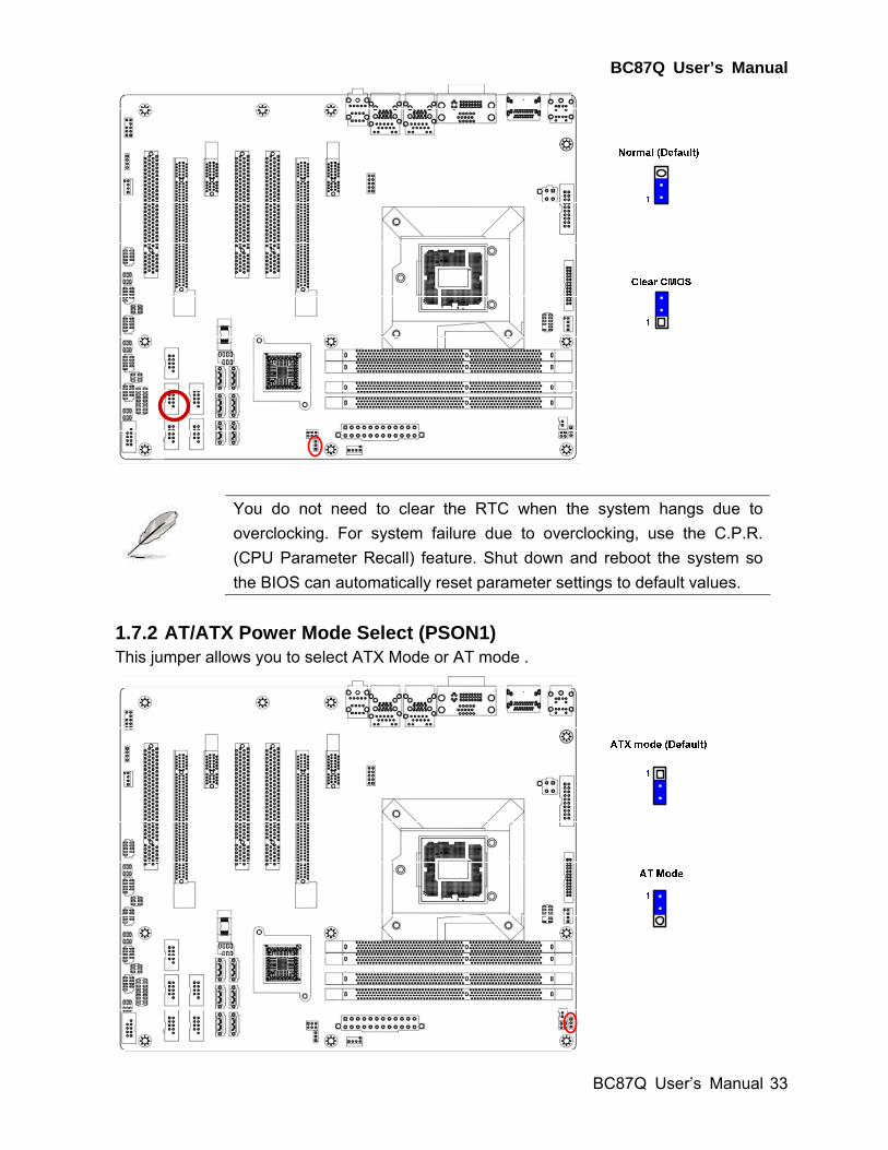
1.7.1 Clear CMOS (JCMOS1).................................................................................................32
1.7.2 AT/ATX Power Mode Select (PSON1) ..........................................................................33
1.7.3 Chassis Intrusion Connector (JCASE1).........................................................................34
1.7.4 COM1 RS232/ RS422/ RS485 Select (JSETCOM1).....................................................34
1.7.5 COM1, COM2, COM3, COM4, COM5 Ring-In/ +12V/ +5V Select (JCOMPWR1,
JCOMPWR2, JCOMPWR3, JCOMPWR4, JCOMPWR5) ......................................................35
1.8 Connectors .................................................................................................................35
1.8.1 Rear panel connectors...................................................................................................35
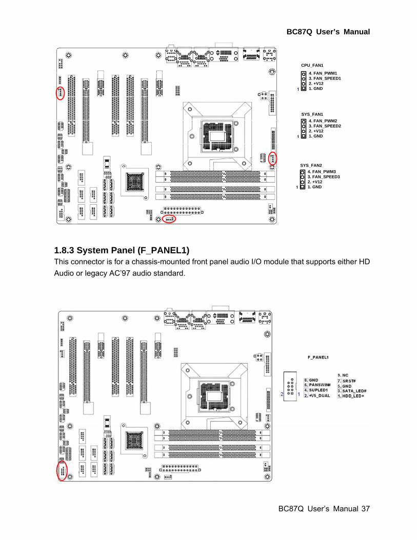
1.8.2 Fan Connectors (CPU_FAN1, SYS_FAN1, SYS_FAN2)..............................................36
1.8.3 System Panel (F_PANEL1) ...........................................................................................37
1.8.4 ATX power connectors (EATXPWR1 (24-Pin), ATX12V1 (4-pin)) ................................38
1.8.5 Serial Port connectors (COM1, COM2, COM3, COM4, COM5)....................................39
1.8.6 Digital IO Connector (JDIO1).........................................................................................40
1.8.7 PARALLEL PORT Connector (LPT2) ............................................................................40
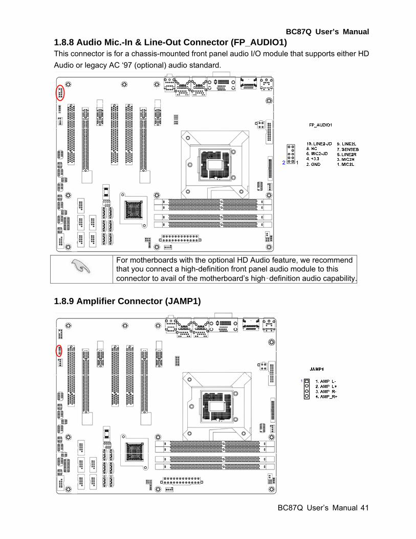
1.8.8 Audio Mic.-In & Line-Out Connector (FP_AUDIO1) ......................................................41
1.8.9 Amplifier Connector (JAMP1) ........................................................................................41
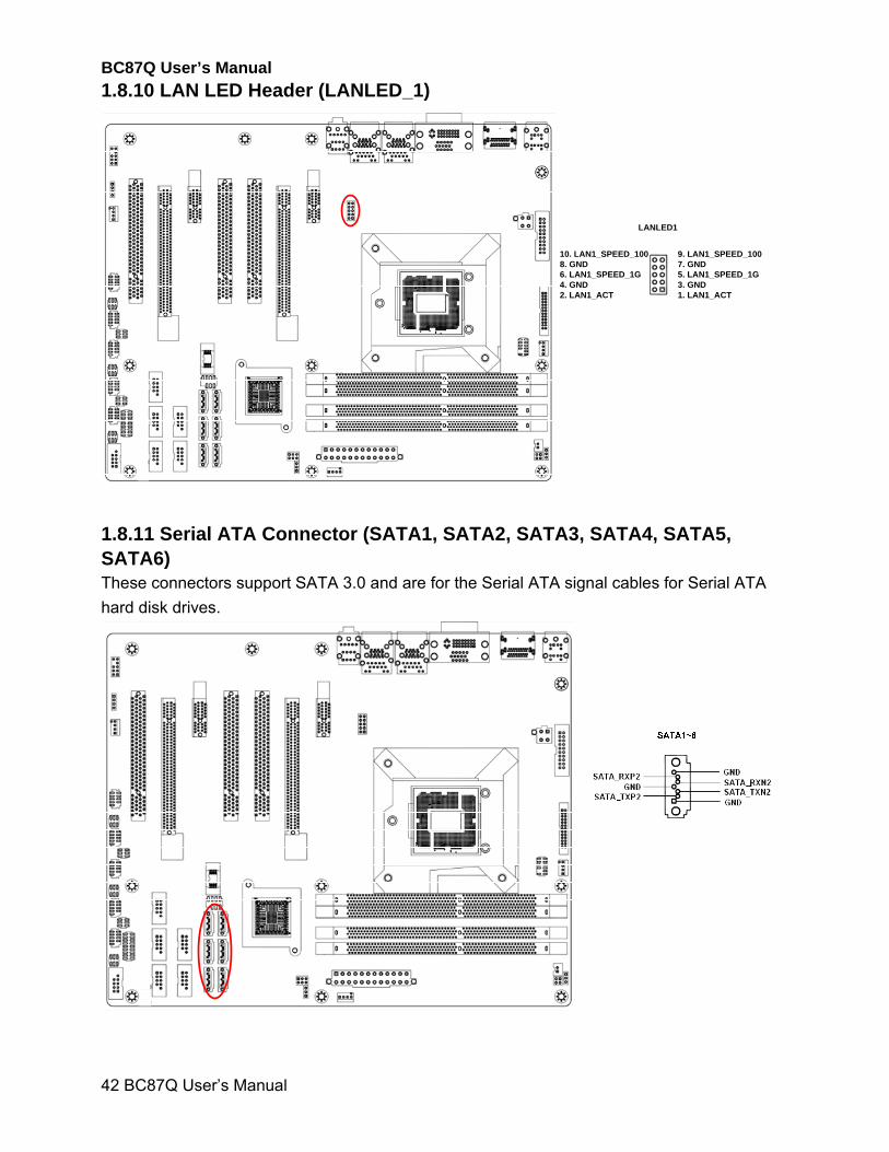
1.8.10 LAN LED Header (LANLED_1)....................................................................................42
BC87Q User’s Manual
BC87Q User’s Manual
3
1.8.11 Serial ATA Connector (SATA1, SATA2, SATA3, SATA4, SATA5, SATA6) ...............42
1.8.12 Front USB Headers: USB34, USB78, USB910, USB1112, USB1314........................43
1.8.13 PC OK Connector (PC_OK1) ......................................................................................44
1.8.14 RAID LED Connector (RAID_LED1) ...........................................................................44
2.1 BIOS Setup Program .................................................................................................46
2.1.1 Legend Box....................................................................................................................47
2.1.2 List Box ..........................................................................................................................47
2.1.3 Sub-menu ......................................................................................................................47
2.2 BIOS Menu Screen.....................................................................................................47
2.3 Main Setup ..................................................................................................................48
2.4 Advanced BIOS Setup ...............................................................................................50
2.4.1 PCI Subsystem Setting..................................................................................................51
2.4.2 ACPI Settings.................................................................................................................52
2.4.3 Trusted computing .........................................................................................................53
2.4.4 CPU configuration..........................................................................................................54
2.4.5 SATA Configuration .......................................................................................................57
2.4.6 PCH-FW Configuration ..................................................................................................58
2.4.7 AMT Configuration .........................................................................................................59
2.4.8 USB Configuration .........................................................................................................60
2.4.9 Super IO Configuration ..................................................................................................61
2.4.10 H/W Monitor .................................................................................................................69
2.4.11 Option ROM Policy ......................................................................................................72
2.4.12 Intel RC Driver Version Detail......................................................................................73
2.5 Chipset ........................................................................................................................74
2.5.1 PCH-IO Configuration....................................................................................................75
2.5.2 System Agent (SA) Configuration..................................................................................82
2.6 Boot .............................................................................................................................87
2.7 Security .......................................................................................................................88
2.8 Save & Exit..................................................................................................................89
BC87Q User’s Manual
4 BC87Q User’s Manual
Safety Information
Electrical safety
To prevent electrical shock hazard, disconnect the power cable from the electrical outlet
before relocating the system.
When adding or removing devices to or from the system, ensure that the power cables
for the devices are unplugged before the signal cables are connected. If possible,
disconnect all power cables from the existing system before you add a device.
Before connecting or removing signal cables from the motherboard, ensure that all
power cables are unplugged.
Seek professional assistance before using an adapter or extension cord. These devices
could interrupt the grounding circuit.
Make sure that your power supply is set to the correct voltage in your area. If you are not
sure about the voltage of the electrical outlet you are using, contact your local power
company.
If the power supply is broken, do not try to fix it by yourself. Contact a qualified service
technician or your retailer.
Operation safety
Before installing the motherboard and adding devices on it, carefully read all the manuals
that came with the package.
Before using the product, make sure all cables are correctly connected and the power
cables are not damaged. If you detect any damage, contact your dealer immediately.
To avoid short circuits, keep paper clips, screws, and staples away from connectors,
slots, sockets and circuitry.
Avoid dust, humidity, and temperature extremes. Do not place the product in any area
where it may become wet.
Place the product on a stable surface.
If you encounter technical problems with the product, contact a qualified service
technician or your retailer.
The symbol of the crossed out wheeled bin indicates that the product (electrical and electronic equipment) should not be placed in municipal waste. Check local regulations for disposal of electronic products.
BC87Q User’s Manual
BC87Q User’s Manual
5
Safety Declaration
This device complies with the requirements in Part 15 of the FCC rules. Operation is subject
to the following two conditions:
This device may not cause harmful interference.
This device must accept any interference received, including interference that may
cause undesired operation.
About this guide This user guide contains the information you need when installing and configuring the
motherboard.
How this guide is organized
This manual contains the following parts:
Chapter 1: Product introduction
This chapter describes the features of the motherboard and the new technology it
supports. This chapter also lists the hardware setup procedures that you have to
perform when installing system components. It includes description of the jumpers and
connectors on the motherboard.
Chapter 2: BIOS setup
This chapter tells how to change system settings through the BIOS Setup menus.
Detailed descriptions of the BIOS parameters are also provided.
Where to find more information
Refer to the following sources for additional information and for product and software
updates.
1. Technical Support
If a problem arises with your system and no solution can be obtained from the user’s manual,
please contact your place of purchase or local distributor.
2. Optional documentation
Your product package may include optional documentation, such as warranty flyers, that may
have been added by your dealer. These documents are not part of the standard package.
BC87Q User’s Manual
6 BC87Q User’s Manual
Conventions used in this guide
To make sure that you perform certain tasks properly, take note of the following symbols
used throughout this manual.
DANGER/WARNING: Information to prevent injury to yourself
when trying to complete a task.
CAUTION: Information to prevent damage to the components
when trying to complete a task.
IMPORTANT: Instructions that you MUST follow to complete a
task.
NOTE: Tips and additional information to help you complete a
task.
Typography
Bold text Indicates a menu or an item to select
Italics Used to emphasize a word or a phrase
<Key> Keys enclosed in the less-than and greater-than sign means
that you must press the enclosed key
Example: <Enter> means that you must press the Enter or
Return key
<Key1>+<Key2>+<Key3> If you must press two or more keys simultaneously, the key
names are linked with a plus sign (+)
Example: <Ctrl>+<Alt>+<D>
Command Means that you must type the command exactly as shown,
then supply the required item or value enclosed in brackets
Example: At the DOS prompt, type the command line:
afudos /i[filename]
afudos /iP5P800VM.ROM
BC87Q User’s Manual
BC87Q User’s Manual
7
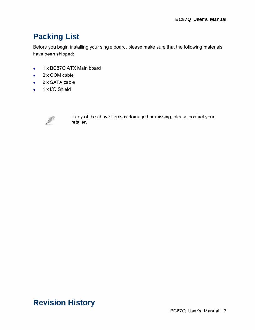
Packing List Before you begin installing your single board, please make sure that the following materials
have been shipped:
1 x BC87Q ATX Main board
2 x COM cable
2 x SATA cable
1 x I/O Shield
If any of the above items is damaged or missing, please contact your retailer.
Revision History
BC87Q User’s Manual
8 BC87Q User’s Manual
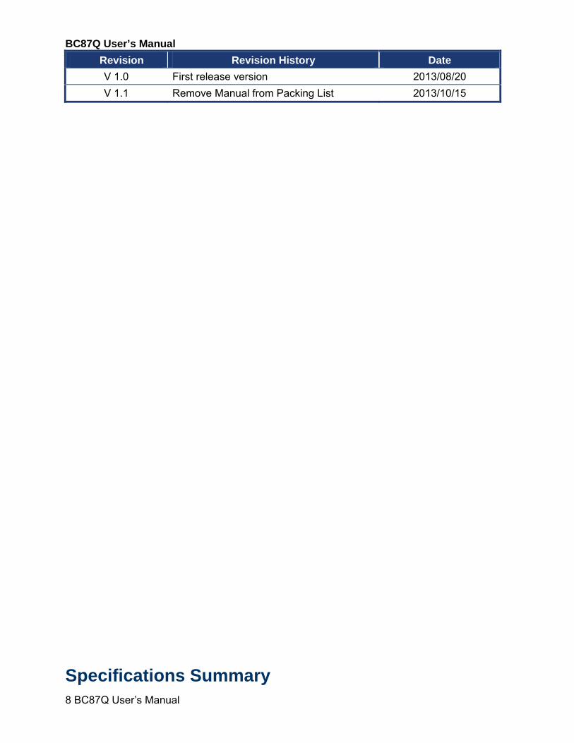
Revision Revision History Date
V 1.0 First release version 2013/08/20
V 1.1 Remove Manual from Packing List 2013/10/15
Specifications Summary
BC87Q User’s Manual
BC87Q User’s Manual
9
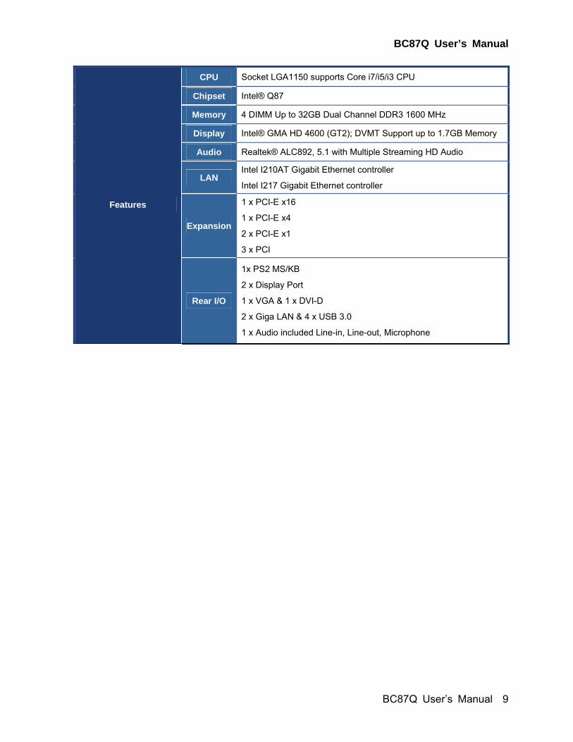
CPU Socket LGA1150 supports Core i7/i5/i3 CPU
Chipset Intel® Q87
Memory 4 DIMM Up to 32GB Dual Channel DDR3 1600 MHz
Display Intel® GMA HD 4600 (GT2); DVMT Support up to 1.7GB Memory
Audio Realtek® ALC892, 5.1 with Multiple Streaming HD Audio
LAN Intel I210AT Gigabit Ethernet controller
Intel I217 Gigabit Ethernet controller
Expansion
1 x PCI-E x16
1 x PCI-E x4
2 x PCI-E x1
3 x PCI
Features
Rear I/O
1x PS2 MS/KB
2 x Display Port
1 x VGA & 1 x DVI-D
2 x Giga LAN & 4 x USB 3.0
1 x Audio included Line-in, Line-out, Microphone
BC87Q User’s Manual
10 BC87Q User’s Manual
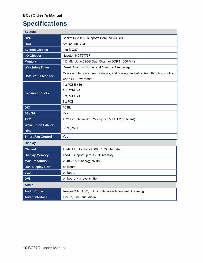
Specifications System
CPU Socket LGA1150 supports Core i7/i5/i3 CPU
BIOS AMI 64 Mb BIOS
System Chipset Intel® Q87
I/O Chipset Nuvoton NCT6776F
Memory 4 DIMM Up to 32GB Dual Channel DDR3 1600 MHz
Watchdog Timer Reset: 1 sec.~255 min. and 1 sec. or 1 min./step
H/W Status Monitor Monitoring temperatures, voltages, and cooling fan status. Auto throttling control
when CPU overheats
Expansion Slots
1 x PCI-E x16
1 x PCI-E x4
2 x PCI-E x1
3 x PCI
DIO 16 Bit
S3 / S4 Yes
TPM TPM1.2 (Infineon® TPM chip 9635 TT 1.2 on board)
Wake up on LAN or
Ring LAN (PXE)
Smart Fan Control Yes
Display
Chipset Intel® HD Graphics 4600 (GT2) integrated
Display Memory DVMT Support up to 1.7GB Memory
Max. Resolution 2048 x 1536 bpp(@ 75Hz)
Dual Display Port on Board
VGA on board
DVI on board, via level shifter
Audio
Audio Codec Realtek® ALC892, 5.1 +2 with two independent Streaming
Audio Interface Line in, Line Out, Mic-in
BC87Q User’s Manual
BC87Q User’s Manual
11
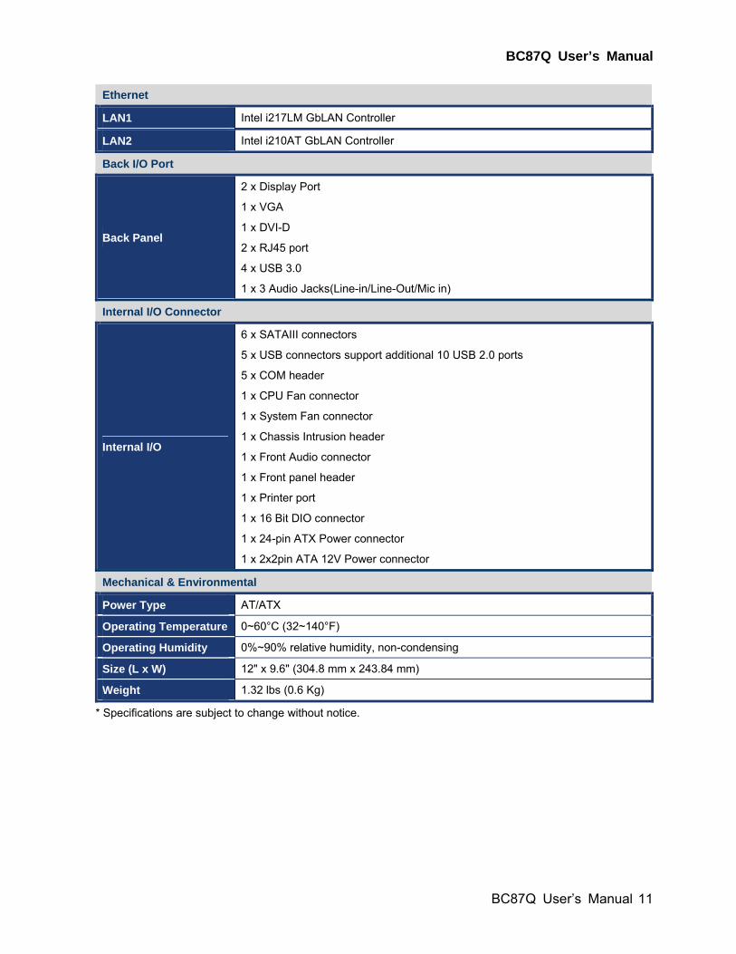
Ethernet
LAN1 Intel i217LM GbLAN Controller
LAN2 Intel i210AT GbLAN Controller
Back I/O Port
Back Panel
2 x Display Port
1 x VGA
1 x DVI-D
2 x RJ45 port
4 x USB 3.0
1 x 3 Audio Jacks(Line-in/Line-Out/Mic in)
Internal I/O Connector
Internal I/O
6 x SATAIII connectors
5 x USB connectors support additional 10 USB 2.0 ports
5 x COM header
1 x CPU Fan connector
1 x System Fan connector
1 x Chassis Intrusion header
1 x Front Audio connector
1 x Front panel header
1 x Printer port
1 x 16 Bit DIO connector
1 x 24-pin ATX Power connector
1 x 2x2pin ATA 12V Power connector
Mechanical & Environmental
Power Type AT/ATX
Operating Temperature 0~60°C (32~140°F)
Operating Humidity 0%~90% relative humidity, non-condensing
Size (L x W) 12" x 9.6" (304.8 mm x 243.84 mm)
Weight 1.32 lbs (0.6 Kg)
* Specifications are subject to change without notice.
BC87Q User’s Manual
12 BC87Q User’s Manual
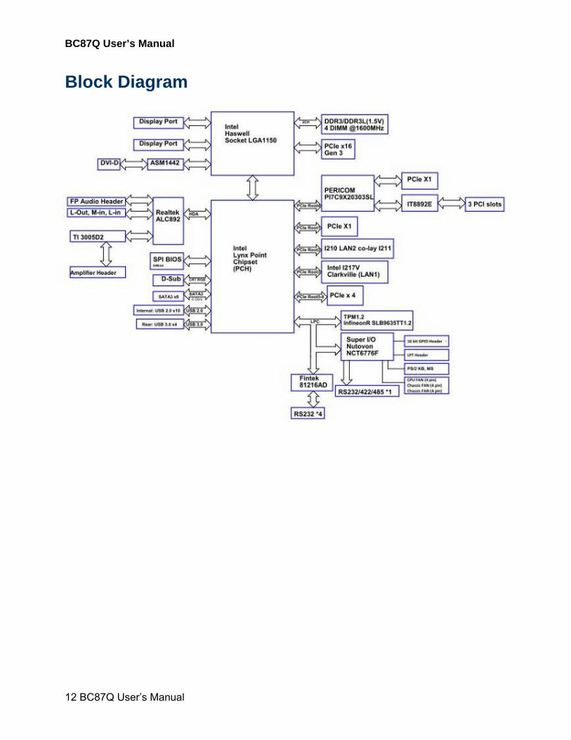
Block Diagram

BC87Q User’s Manual
BC87Q User’s Manual
13
Product Introduction
This chapter describes the
motherboard features and the
new technologies it supports.
1

BC87Q User’s Manual
14 BC87Q User’s Manual
Chapter 1 - Product Introduction
1.1 Product highlights
1.1.1 Product Overview Supports latest Intel LGA 1150 CPU-socket interface processor, the 4th Generation Intel®
Core i7/i5/i3 Haswell desktop processors which are built on 22 nm technologies to provide
smart performance and responsiveness on executing tasks, It combines the CPU and GPU to
offer fantastic HD media and graphics, especiallyon 3D gaming experience. Doubles the
bandwidth of your system memory up to 16GB/s and pumps up the system performance at
lower power.
DMI (Direct Media Interface) architecture connects between the processor and chipset at
5.0GT/s which twice the speed of previous version. The exceptionally increased interconnect
bit rate from 2.5GT/s up to 5.0GT/s would effectively eliminates the bottle neck of the system
performance and brings the most terrific computing experience fromthe present to the future.
SATA 3.0 doubles the transfer speed of SATA 2.0,running at speed up to 6.0Gb/s, and can
connect with any other SATA 3.0Gb/s and 1.5Gb/s devices for backward compatibility.
Supports RAID 0(Striped disk array), RAID 1(Mirroring disk array), RAID 5(Block Interleaved
Distributed Parity), RAID 10 (A Stripe of Mirrors). Provides users the performance and
protection. Integrated 5.1-channel HD Audio CODEC delivering advanced multi-channel
audio and bringing you the experience of home theater-quality sound. Delivers transfer speed
ten times faster than conventional 10/ 100 Ethernet connections, supporting a high transfer
rate up to Gigabit/s. Gigabit LAN is the networking standards for the future and is ideal for
handing large amount of data such as video, audio, and voice.
Choose an environment-friendly, fully RoHS-compliant ECS product as the foundation for
keeping harmful substances out of our ecosystem.
1.1.2 Platform Features and Benefits •Integrated Gfx (Intel® HD Graphics 4600) with enhanced operating modes to enable
excellent graphics performance in power and cost sensitive embedded applications
• DirectX® 11.1 & Open GL 3.2 let you enjoy awesome graphics performance, stunning 3D
visual effect and dynamic interactivity
• Memory support, integrated low voltage DDR3 memory controller
• Operating system support:
- Microsoft
BC87Q User’s Manual
BC87Q User’s Manual
15
-WindRiver
-Redhat
-Novell
-Green Hills
-QNX
- LinuxWorks
1.1.3 Key Architecture Features • Supports Intel LGA 1150 CPU, the 4th Generation Intel® Core i3, i5, i7 desktop processors.
-22nm monolithic die
-Integrated Gfx Intel® HD Graphics 4600 (GT2) & memory controller
-4 &2 Cores, up to 6MB LLC
-HW accelerated video CODECs
- Compatible with high speed DDR3-1600
-PCIe* (CPU): Gen 3.0, 8GT/s, up to 20 lanes (4 ctls)**
-TDP: 35W-45W (Low Power), 65W-95W (Scalable)
• Intel® Turbo Boost Technology 2.0
-More efficient power sharing between CPU and Graphics
• Intel® Hyper-Threading Technology
• Intel® Advanced Vector Extensions (Intel® AVX)
•Transactional Synchronization Extensions (TSX)
• Integrated Display Interfaces
- Dual Independent Display Support
- DVI-D
- Analog VGA
• Intel® HD Graphics 4600
- DirectX® 11.1
- Improved realism for DX 3D applications. Improved rendering.
- OpenGL 3.2
- Improved realism for OGL 3D based application
- UVD (Unified Video Decoder) 2.01
Hardware decode of most common HD codecs (MPEG-2, H.264/AVC MPEG-4 and
VC-1)
- Supports ATI Hybrid CrossFireXTM Technology2
• Intel Quick Sync Video
- Enables faster and higher quality video editing, recording and sharing
• I/O
- PCI Express® x 16 Gen 3 8GT/s
- Six SATA III ports support RAID 0,1, 5, 10
- Gigabit Ethernet Media Access Controller (GbE MAC)
BC87Q User’s Manual
16 BC87Q User’s Manual
IPv4 and IPv6 Checksum Offload
- High Definition Audio
- USB: 4 x Gen 3.0 and 10 x Gen 2.0
- SMBus 2.0
- LPC Bus
Supports SPI devices
- Hardware Monitor
Fan control (Voltage, Temp)
Watchdog timer
• Power Management
- Dual Dynamic Power Management
Separate power planes for cores and memory controller
- Advanced Configuration and Power Interface (ACPI) 3.0
1.2 Before you Proceed
Take note of the following precautions before you install motherboard components or change
any motherboard settings.
Unplug the power cord from the wall socket before touching any component.
Use a grounded wrist strap or touch a safely grounded object or a metal object, such as the power supply case, before handling components to avoid damaging them due to static electricity
Hold components by the edges to avoid touching the ICs on them.
Whenever you uninstall any component, place it on a grounded anti-static pad or in the bag that came with the component.
Before you install or remove any component, ensure that the ATX power supply is switched off or the power cord is detached from the power supply. Failure to do so may cause severe damage to the motherboard, peripherals, and/or components.
BC87Q User’s Manual
BC87Q User’s Manual
17
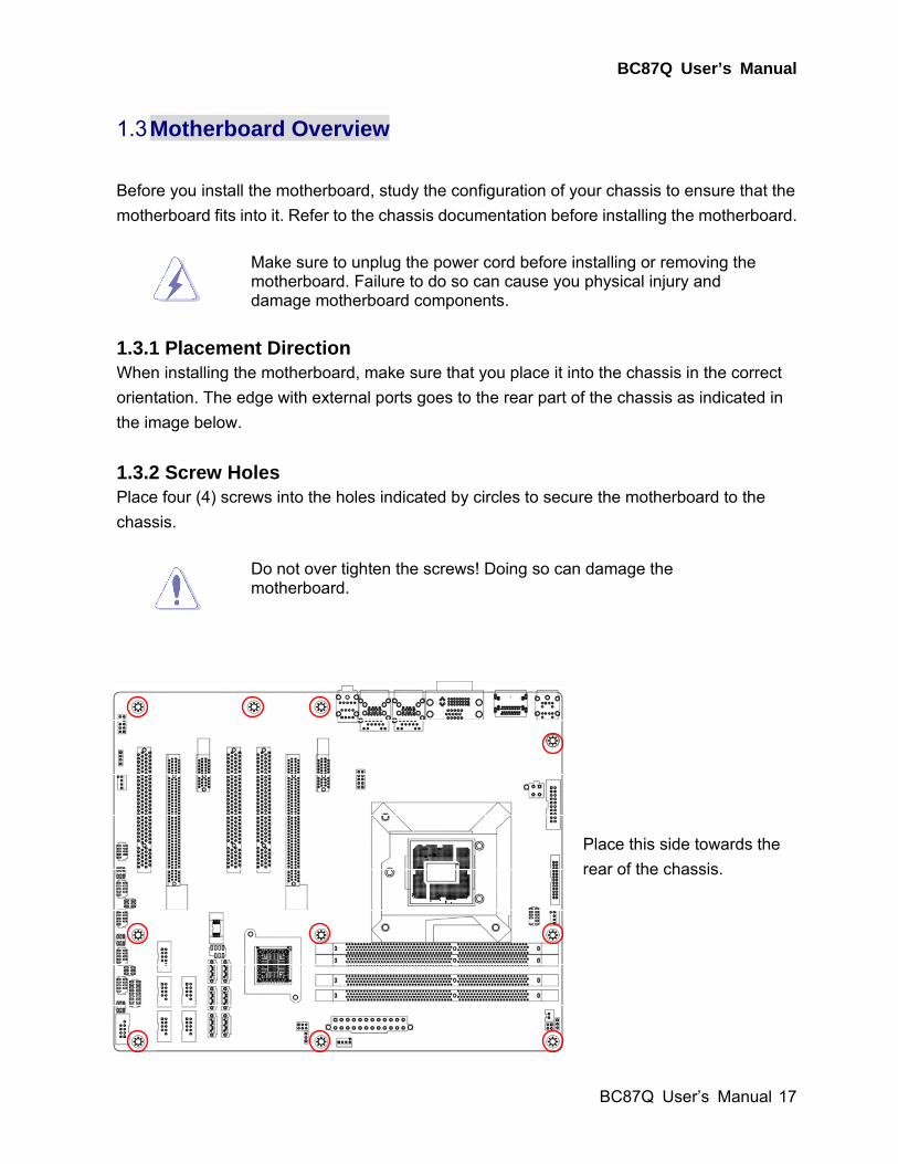
1.3 Motherboard Overview
Before you install the motherboard, study the configuration of your chassis to ensure that the
motherboard fits into it. Refer to the chassis documentation before installing the motherboard.
Make sure to unplug the power cord before installing or removing the motherboard. Failure to do so can cause you physical injury and damage motherboard components.
1.3.1 Placement Direction
When installing the motherboard, make sure that you place it into the chassis in the correct
orientation. The edge with external ports goes to the rear part of the chassis as indicated in
the image below.
1.3.2 Screw Holes Place four (4) screws into the holes indicated by circles to secure the motherboard to the
chassis.
Do not over tighten the screws! Doing so can damage the motherboard.
Place this side towards the
rear of the chassis.
BC87Q User’s Manual
18 BC87Q User’s Manual
1.3.3 Motherboard Layout
LGA1150
ATX12V1
JDIO
LPT2
CPU_FAN1
DIMM_A1
DIMM_A2
DIMM_B1
DIMM_B2
JCASE1JPSON1
PC_OK1EATXPWR1SYS_FAN2
JCMOS1RAID_LED1
SA
TA
1S
AT
A3
SA
TA
5
SA
TA
2S
AT
A4
SA
TA
6US
B1
11
2U
SB
13
14
US
B7
8
US
B3
4U
SB
91
0
F_PANEL1
JCOMPWR1
JSETCOM1
JCOMPWR2
JCOMPWR3
JCOMPWR4
JCOMPWR5
COM1
COM2
COM3
COM4
COM5
FP_AUDIO1
JAMP1
PCI3PCIEX4_1
PCIEX1_2PCI2
PCI3PCIEX16_1
PCIEX1_1AUDIO1
LAN2_USB56LAN1_USB12
DVI1_VGA1DP1 KBMS1
SYS_FAN1
1.3.4 Layout Content List
Slots & socket
Label Function Note Page
LGA1155 LGA1150 socket 20
DIMM_A1 240-pin DDR3 DIMM Slot A1 26
DIMM_A2 240-pin DDR3 DIMM Slot A2 26
DIMM_B1 240-pin DDR3 DIMM Slot B1 26
DIMM_B2 240-pin DDR3 DIMM Slot B2 26
PCIEX16_1 PCI-e x16 Slot 30
PCIEX4_1 PCI-e x4 Slot 31
PCIEX1_1~2 PCI-e x1 Slot 31
PCI1~3 PCI Slot 32
BC87Q User’s Manual
BC87Q User’s Manual
19
Jumpers
Label Function Note Page
JCMOS1 Load CMOS Default 3 x 1 header, pitch 2.54mm 32
PSON1 AT/ATX Power Select 3 x 1 header, pitch 2.54mm 33
JSETCOM1 COM1 RS232/ RS422/ RS485
Select
9 x 2 header, pitch 2.00mm 34
JCOMPWR1~5 COM1 5 RI/+5V/+12V Select 3 x 2 header, pitch 2.00mm 35
Rear Panel Connector
Label Function Note Page
KB/MS PS/2 keyboard and mouse 35,36
DP1 Display Port Connector x 2 35,36
DVI1_VGA1 VGA Connector
DVI Connector
D-sub 15-pin, female
Dual Link DVI-D; 24 pins
35,36
LAN1_USB12
RJ-45 Ethernet Connector x 1
USB Connector x 2
35,36
LAN2_USB56 RJ-45 Ethernet Connector x 1
USB Connector x 2
35,36
AUDIO1 Line-in Port, Line-out Port,
Microphone Port,
5.1 Channel Audio I/O (3 jacks) 35,36
Internal Connector
Label Function Note Page
F_PANEL1 System Panel Connector 5 x 2 wafer, pitch 2.54mm 37
ATX12V1 ATX 12V Connector 2 x 2 connector 38
EATXPWR1 ATX Power Connector 12 x 2 connector 38
CPU_FAN1 CPU Fan Connector 4 x 1 wafer, pitch 2.54mm 36
SYS_FAN1 System Fan Connector 4 x 1 wafer, pitch 2.54mm 36
SYS_FAN2 System Fan Connector 4 x 1 wafer, pitch 2.54mm 36
COM 1~5 Serial Port Connector 1~5 5 x 2 wafer, pitch 2.0mm 39
JDIO Digital I/O Connector 10 x 2 wafer, pitch 2.54mm 40
FP_AUDIO1 Front Panel Audio Connector 5 x 2 header, pitch 2.54mm 41
JAMP1 Amplifier Connector 4 x 1 header, pitch 2.54mm 41
LANLED1 LAN LED header 5 x 2 header, pitch 2.54mm 42
SATA1~6 Serial ATA Connectors 1~4 7-pin header 42
USB34/78/910/1
112/1314
USB 2.0 Connector 5 x 2 wafer, pitch 2.54mm 43
BC87Q User’s Manual
20 BC87Q User’s Manual
RAID_LED1 RAID LED header 3 x 2 header, pitch 2.54mm 44
PC_OK1 PC OK LED header 2 x 2 header, pitch 2.54mm 44
1.4 Central Processing Unit (CPU)
The motherboard comes with a surface mount LGA1150 socket designed for the Intel®
Core™ i7/ i5/ i3 processor in the 1150-land package.
Your boxed Intel® Core™ i7/ i5/ i3 LGA1150 processor package
should come with installation instructions for the CPU, fan and
heatsink assembly. If the instructions in this section do not match
the CPU documentation, follow the latter.
Upon purchase of the motherboard, make sure that the PnP cap
is on the socket and the socket pins are not bent. Contact your
retailer immediately if the PnP cap is missing, or if you see any
damage to the PnP cap/socket pins/motherboard components.
BCM will shoulder the cost of repair only if the damage is
shipment/transit-related.
Keep the cap after installing the motherboard. BCM will process
Return Merchandise Authorization (RMA) requests only if the
motherboard comes with the cap on the LGA1150 socket.
The product warranty does not cover damage to the socket pins
resulting from incorrect CPU installation/removal, or
misplacement/loss/incorrect removal of the PnP cap.
Install the CPU fan and heatsink assembly before you install
motherboard to the chassis.
If you purchased a separate CPU heatsink and fan assembly, make
sure that you have properly applied Thermal Interface Material to the
CPU heatsink or CPU before you install the heatsink and fan
assembly.
BC87Q User’s Manual
BC87Q User’s Manual
21
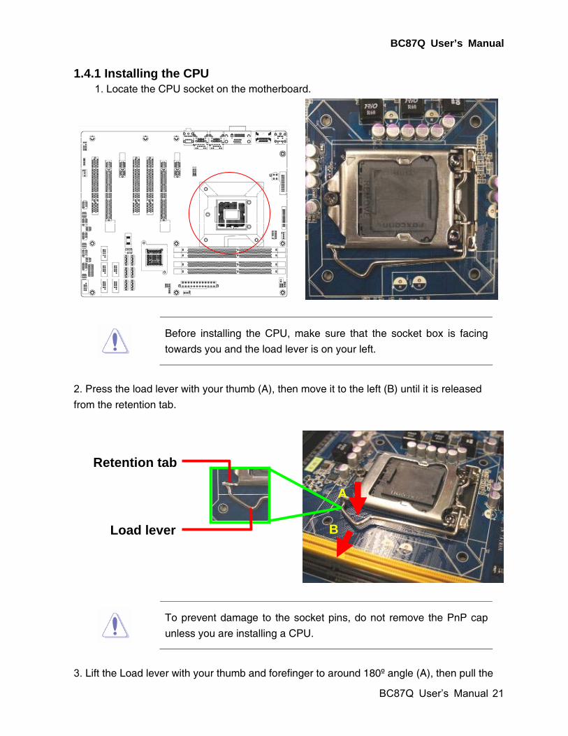
1.4.1 Installing the CPU 1. Locate the CPU socket on the motherboard.
Before installing the CPU, make sure that the socket box is facing
towards you and the load lever is on your left.
2. Press the load lever with your thumb (A), then move it to the left (B) until it is released
from the retention tab.
To prevent damage to the socket pins, do not remove the PnP cap
unless you are installing a CPU.
3. Lift the Load lever with your thumb and forefinger to around 180º angle (A), then pull the
A
B
Retention tab
Load lever
BC87Q User’s Manual
22 BC87Q User’s Manual
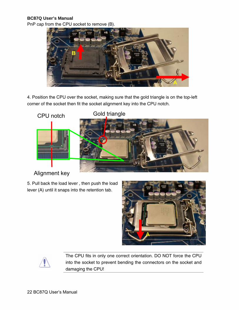
PnP cap from the CPU socket to remove (B).
4. Position the CPU over the socket, making sure that the gold triangle is on the top-left
corner of the socket then fit the socket alignment key into the CPU notch.
5. Pull back the load lever , then push the load
lever (A) until it snaps into the retention tab.
The CPU fits in only one correct orientation. DO NOT force the CPU
into the socket to prevent bending the connectors on the socket and
damaging the CPU!
Alignment key
CPU notch Gold triangle
B
A
A
BC87Q User’s Manual
BC87Q User’s Manual
23
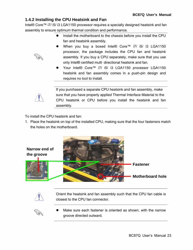
1.4.2 Installing the CPU Heatsink and Fan Intel® Core™ i7/ i5/ i3 LGA1150 processor requires a specially designed heatsink and fan
assembly to ensure optimum thermal condition and performance.
Install the motherboard to the chassis before you install the CPU
fan and heatsink assembly.
When you buy a boxed Intel® Core™ i7/ i5/ i3 LGA1150
processor, the package includes the CPU fan and heatsink
assembly. If you buy a CPU separately, make sure that you use
only Intel® certified multi‑directional heatsink and fan.
Your Intel® Core™ i7/ i5/ i3 LGA1150 processor LGA1150
heatsink and fan assembly comes in a push-pin design and
requires no tool to install.
If you purchased a separate CPU heatsink and fan assembly, make
sure that you have properly applied Thermal Interface Material to the
CPU heatsink or CPU before you install the heatsink and fan
assembly.
To install the CPU heatsink and fan:
1. Place the heatsink on top of the installed CPU, making sure that the four fasteners match
the holes on the motherboard.
Orient the heatsink and fan assembly such that the CPU fan cable is
closest to the CPU fan connector.
Make sure each fastener is oriented as shown, with the narrow
groove directed outward.
Motherboard hole
Fastener
Narrow end of the groove
BC87Q User’s Manual
24 BC87Q User’s Manual
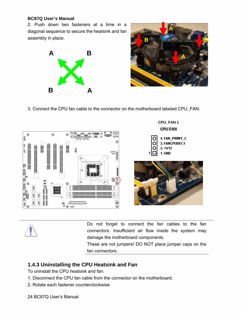
2. Push down two fasteners at a time in a
diagonal sequence to secure the heatsink and fan
assembly in place.
3. Connect the CPU fan cable to the connector on the motherboard labeled CPU_FAN.
CPU_FAN 1
CPU FAN
Do not forget to connect the fan cables to the fan
connectors. Insufficient air flow inside the system may
damage the motherboard components.
These are not jumpers! DO NOT place jumper caps on the
fan connectors.
1.4.3 Uninstalling the CPU Heatsink and Fan To uninstall the CPU heatsink and fan:
1. Disconnect the CPU fan cable from the connector on the motherboard.
2. Rotate each fastener counterclockwise
A
A
B
B
A
B
A
B
BC87Q User’s Manual
BC87Q User’s Manual
25
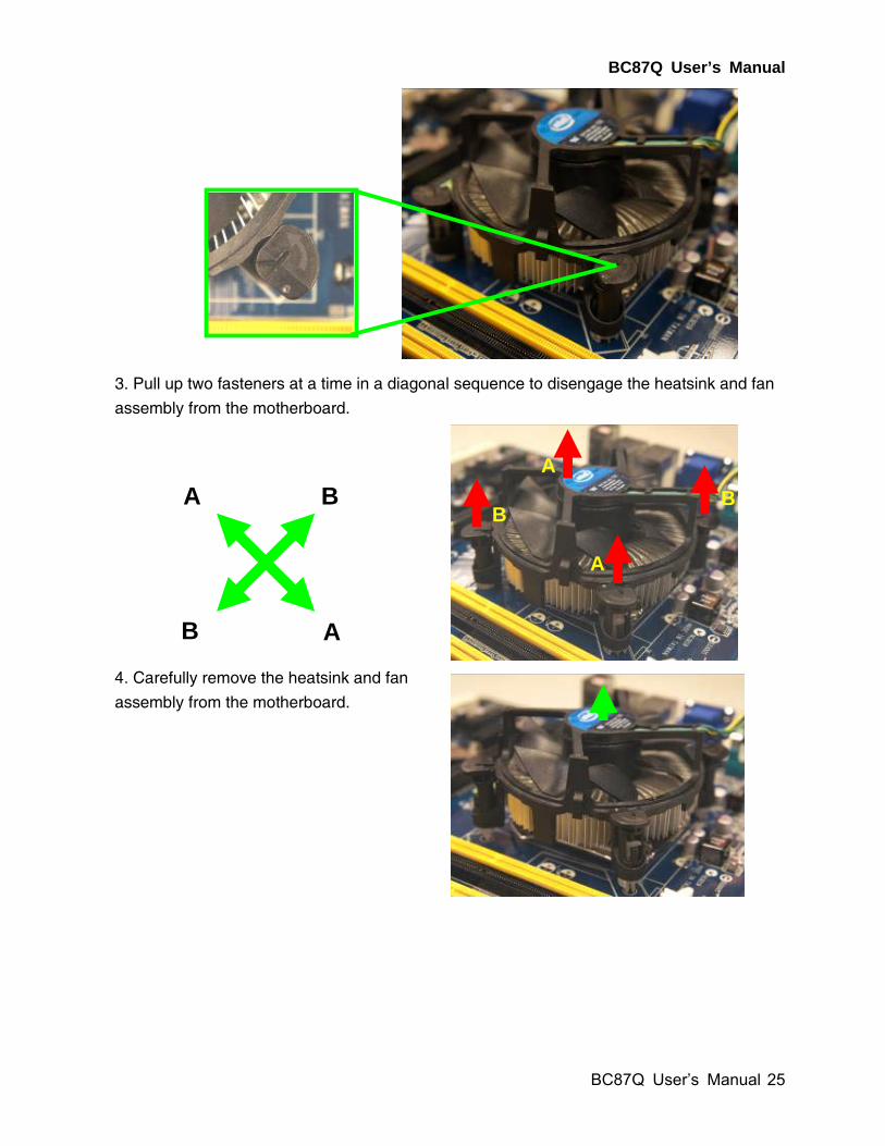
3. Pull up two fasteners at a time in a diagonal sequence to disengage the heatsink and fan
assembly from the motherboard.
4. Carefully remove the heatsink and fan
assembly from the motherboard.
A
B
A
B
A
A
B
B
BC87Q User’s Manual
26 BC87Q User’s Manual
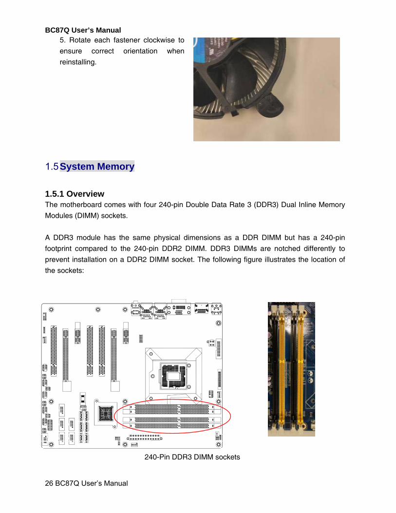
5. Rotate each fastener clockwise to
ensure correct orientation when
reinstalling.
1.5 System Memory
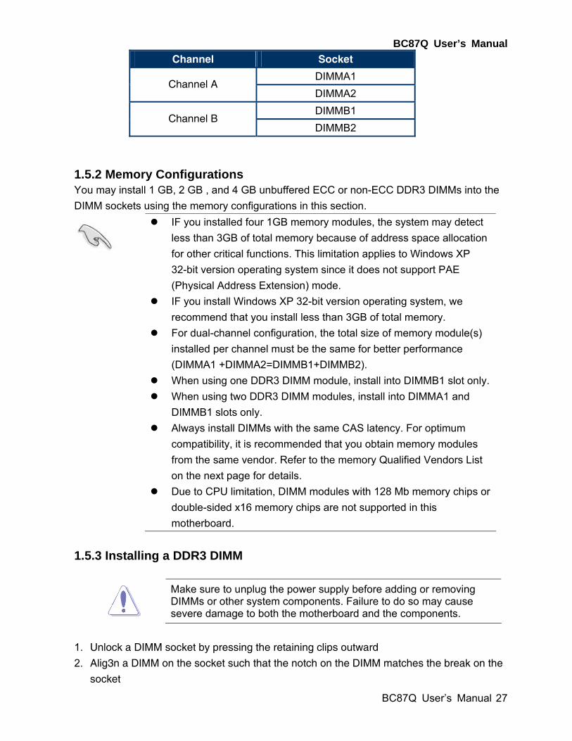
1.5.1 Overview The motherboard comes with four 240-pin Double Data Rate 3 (DDR3) Dual Inline Memory
Modules (DIMM) sockets.
A DDR3 module has the same physical dimensions as a DDR DIMM but has a 240-pin
footprint compared to the 240-pin DDR2 DIMM. DDR3 DIMMs are notched differently to
prevent installation on a DDR2 DIMM socket. The following figure illustrates the location of
the sockets:
240-Pin DDR3 DIMM sockets
BC87Q User’s Manual
BC87Q User’s Manual
27
Channel Socket
DIMMA1 Channel A
DIMMA2
DIMMB1 Channel B
DIMMB2
1.5.2 Memory Configurations You may install 1 GB, 2 GB , and 4 GB unbuffered ECC or non-ECC DDR3 DIMMs into the
DIMM sockets using the memory configurations in this section.
IF you installed four 1GB memory modules, the system may detect
less than 3GB of total memory because of address space allocation
for other critical functions. This limitation applies to Windows XP
32-bit version operating system since it does not support PAE
(Physical Address Extension) mode.
IF you install Windows XP 32-bit version operating system, we
recommend that you install less than 3GB of total memory.
For dual-channel configuration, the total size of memory module(s)
installed per channel must be the same for better performance
(DIMMA1 +DIMMA2=DIMMB1+DIMMB2).
When using one DDR3 DIMM module, install into DIMMB1 slot only.
When using two DDR3 DIMM modules, install into DIMMA1 and
DIMMB1 slots only.
Always install DIMMs with the same CAS latency. For optimum
compatibility, it is recommended that you obtain memory modules
from the same vendor. Refer to the memory Qualified Vendors List
on the next page for details.
Due to CPU limitation, DIMM modules with 128 Mb memory chips or
double-sided x16 memory chips are not supported in this
motherboard.
1.5.3 Installing a DDR3 DIMM
Make sure to unplug the power supply before adding or removing DIMMs or other system components. Failure to do so may cause severe damage to both the motherboard and the components.
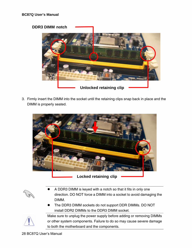
1. Unlock a DIMM socket by pressing the retaining clips outward
2. Alig3n a DIMM on the socket such that the notch on the DIMM matches the break on the
socket
BC87Q User’s Manual
28 BC87Q User’s Manual
3. Firmly insert the DIMM into the socket until the retaining clips snap back in place and the
DIMM is properly seated.
A DDR3 DIMM is keyed with a notch so that it fits in only one
direction. DO NOT force a DIMM into a socket to avoid damaging the
DIMM.
The DDR3 DIMM sockets do not support DDR DIMMs. DO NOT
install DDR2 DIMMs to the DDR3 DIMM socket.
Make sure to unplug the power supply before adding or removing DIMMs
or other system components. Failure to do so may cause severe damage
to both the motherboard and the components.
Locked retaining clip
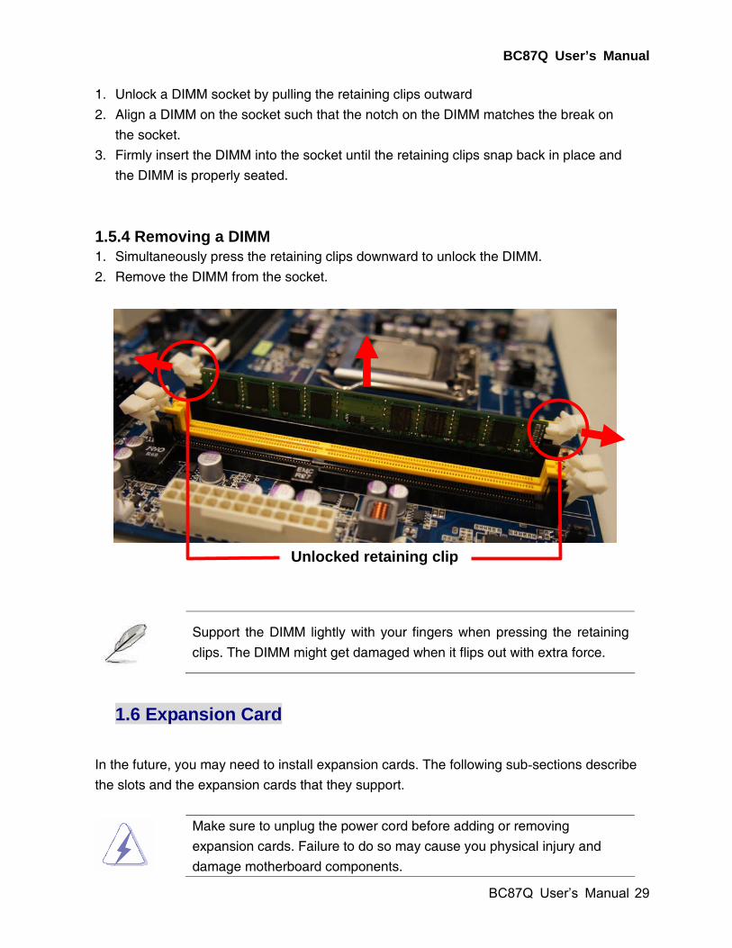
Unlocked retaining clip
DDR3 DIMM notch
BC87Q User’s Manual
BC87Q User’s Manual
29
1. Unlock a DIMM socket by pulling the retaining clips outward
2. Align a DIMM on the socket such that the notch on the DIMM matches the break on
the socket.
3. Firmly insert the DIMM into the socket until the retaining clips snap back in place and
the DIMM is properly seated.
1.5.4 Removing a DIMM 1. Simultaneously press the retaining clips downward to unlock the DIMM.
2. Remove the DIMM from the socket.
Support the DIMM lightly with your fingers when pressing the retaining
clips. The DIMM might get damaged when it flips out with extra force.
1.6 Expansion Card
In the future, you may need to install expansion cards. The following sub-sections describe
the slots and the expansion cards that they support.
Make sure to unplug the power cord before adding or removing
expansion cards. Failure to do so may cause you physical injury and
damage motherboard components.
Unlocked retaining clip
BC87Q User’s Manual
30 BC87Q User’s Manual
1.6.1 Installing an Expansion Card
1. Before installing the expansion card, read the documentation that came with it and make
the necessary hardware settings for the card.
2. Remove the system unit cover (if your motherboard is already installed in a chassis).
3. Remove the bracket opposite the slot that you intend to use. Keep the screw for later use.
4. Align the card connector with the slot and press firmly until the card is completely seated
on the slot.
5. Secure the card to the chassis with the screw you removed earlier.
6. Replace the system cover.
1.6.2 Configuring an Expansion Card
After installing the expansion card, configure it by adjusting the software settings.
1. Turn on the system and change the necessary BIOS settings, if any. See Chapter 2 for
information on BIOS setup.
2. Assign an IRQ to the card if needed. Refer to the tables on the next page.
3. Install the software drivers for the expansion card.
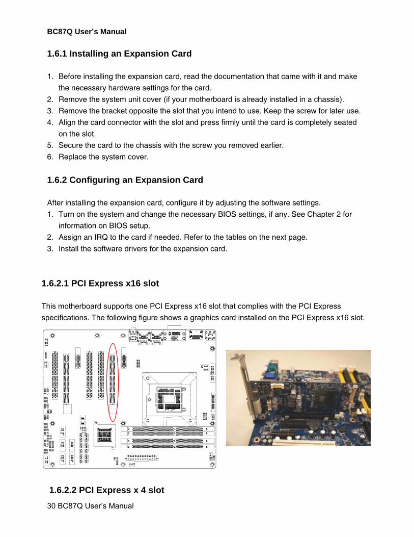
1.6.2.1 PCI Express x16 slot
This motherboard supports one PCI Express x16 slot that complies with the PCI Express
specifications. The following figure shows a graphics card installed on the PCI Express x16 slot.
1.6.2.2 PCI Express x 4 slot
BC87Q User’s Manual
BC87Q User’s Manual
31
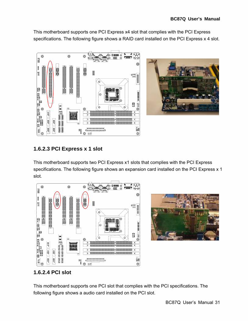
This motherboard supports one PCI Express x4 slot that complies with the PCI Express
specifications. The following figure shows a RAID card installed on the PCI Express x 4 slot.
1.6.2.3 PCI Express x 1 slot
This motherboard supports two PCI Express x1 slots that complies with the PCI Express
specifications. The following figure shows an expansion card installed on the PCI Express x 1
slot.
1.6.2.4 PCI slot
This motherboard supports one PCI slot that complies with the PCI specifications. The
following figure shows a audio card installed on the PCI slot.
BC87Q User’s Manual
32 BC87Q User’s Manual
1.7 Jumpers
1.7.1 Clear CMOS (JCMOS1) This jumper allows you to clear the Real Time Clock (RTC) RAM in CMOS. You can clear the
CMOS memory of date, time, and system setup parameters by erasing the CMOS RTC RAM
data. The onboard button cell battery powers the RAM data in CMOS, which includes system
setup information such as system passwords.
To erase the RTC RAM:
1. Turn OFF the computer and unplug the power cord.
2. Remove the onboard battery.
3. Move the jumper cap from pins 1-2 (default) to pins 2-3. Keep the cap on pins 2-3 for
about 5~10 seconds, then move the cap back to pins 1-2.
4. Re-install the battery.
5. Plug the power cord and turn ON the computer.
6. Hold down the <Del> key during the boot process and enter BIOS setup to re-enter data.
BC87Q User’s Manual
BC87Q User’s Manual
33
You do not need to clear the RTC when the system hangs due to
overclocking. For system failure due to overclocking, use the C.P.R.
(CPU Parameter Recall) feature. Shut down and reboot the system so
the BIOS can automatically reset parameter settings to default values.
1.7.2 AT/ATX Power Mode Select (PSON1) This jumper allows you to select ATX Mode or AT mode .
BC87Q User’s Manual
34 BC87Q User’s Manual
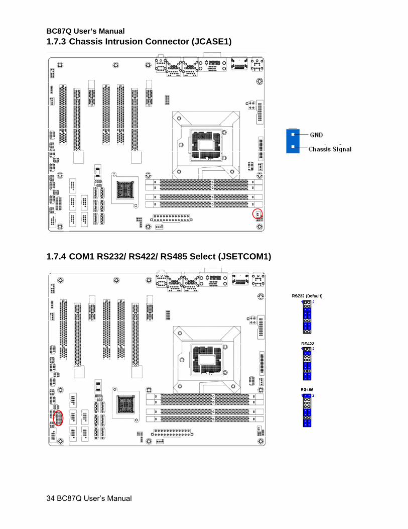
1.7.3 Chassis Intrusion Connector (JCASE1)
1.7.4 COM1 RS232/ RS422/ RS485 Select (JSETCOM1)
BC87Q User’s Manual
BC87Q User’s Manual
35
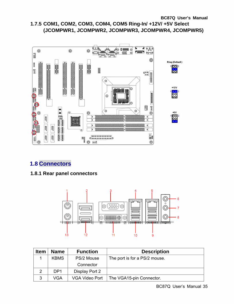
1.7.5 COM1, COM2, COM3, COM4, COM5 Ring-In/ +12V/ +5V Select (JCOMPWR1, JCOMPWR2, JCOMPWR3, JCOMPWR4, JCOMPWR5)
1.8 Connectors
1.8.1 Rear panel connectors
Item Name Function Description 1 KBMS PS/2 Mouse
Connector
The port is for a PS/2 mouse.
2 DP1 Display Port 2
3 VGA VGA Video Port The VGA15-pin Connector.
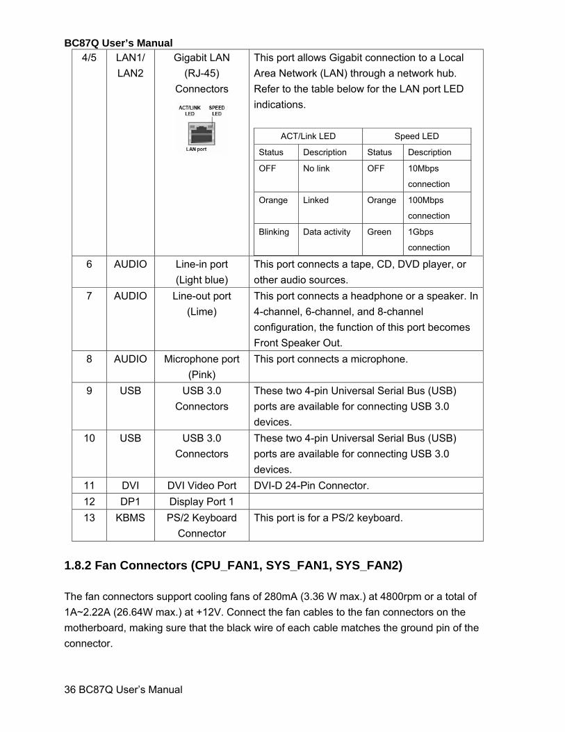
BC87Q User’s Manual
36 BC87Q User’s Manual
4/5 LAN1/
LAN2
Gigabit LAN
(RJ-45)
Connectors
This port allows Gigabit connection to a Local
Area Network (LAN) through a network hub.
Refer to the table below for the LAN port LED
indications.
ACT/Link LED Speed LED
Status Description Status Description
OFF No link OFF 10Mbps
connection
Orange Linked Orange 100Mbps
connection
Blinking Data activity Green 1Gbps
connection 6 AUDIO Line-in port
(Light blue)
This port connects a tape, CD, DVD player, or
other audio sources.
7 AUDIO Line-out port
(Lime)
This port connects a headphone or a speaker. In
4-channel, 6-channel, and 8-channel
configuration, the function of this port becomes
Front Speaker Out.
8 AUDIO Microphone port
(Pink)
This port connects a microphone.
9 USB USB 3.0
Connectors
These two 4-pin Universal Serial Bus (USB)
ports are available for connecting USB 3.0
devices.
10 USB USB 3.0
Connectors
These two 4-pin Universal Serial Bus (USB)
ports are available for connecting USB 3.0
devices.
11 DVI DVI Video Port DVI-D 24-Pin Connector.
12 DP1 Display Port 1
13 KBMS PS/2 Keyboard
Connector
This port is for a PS/2 keyboard.
1.8.2 Fan Connectors (CPU_FAN1, SYS_FAN1, SYS_FAN2) The fan connectors support cooling fans of 280mA (3.36 W max.) at 4800rpm or a total of
1A~2.22A (26.64W max.) at +12V. Connect the fan cables to the fan connectors on the
motherboard, making sure that the black wire of each cable matches the ground pin of the
connector.
BC87Q User’s Manual
BC87Q User’s Manual
37
CPU_FAN1
SYS_FAN1
SYS_FAN2
4. FAN_PWM33. FAN_SPEED32. +V121. GND
4. FAN_PWM23. FAN_SPEED22. +V121. GND
4. FAN_PWM13. FAN_SPEED12. +V121. GND
1.8.3 System Panel (F_PANEL1) This connector is for a chassis-mounted front panel audio I/O module that supports either HD
Audio or legacy AC’97 audio standard.
BC87Q User’s Manual
38 BC87Q User’s Manual
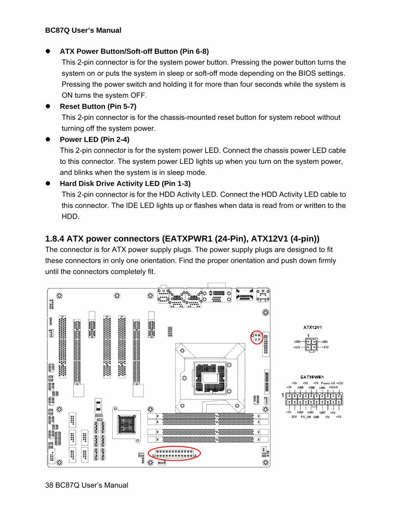
ATX Power Button/Soft-off Button (Pin 6-8)
This 2-pin connector is for the system power button. Pressing the power button turns the
system on or puts the system in sleep or soft-off mode depending on the BIOS settings.
Pressing the power switch and holding it for more than four seconds while the system is
ON turns the system OFF.
Reset Button (Pin 5-7)
This 2-pin connector is for the chassis-mounted reset button for system reboot without
turning off the system power.
Power LED (Pin 2-4)
This 2-pin connector is for the system power LED. Connect the chassis power LED cable
to this connector. The system power LED lights up when you turn on the system power,
and blinks when the system is in sleep mode.
Hard Disk Drive Activity LED (Pin 1-3)
This 2-pin connector is for the HDD Activity LED. Connect the HDD Activity LED cable to
this connector. The IDE LED lights up or flashes when data is read from or written to the
HDD.
1.8.4 ATX power connectors (EATXPWR1 (24-Pin), ATX12V1 (4-pin)) The connector is for ATX power supply plugs. The power supply plugs are designed to fit
these connectors in only one orientation. Find the proper orientation and push down firmly
until the connectors completely fit.
BC87Q User’s Manual
BC87Q User’s Manual
39
Use of a PSU with a higher power output is recommended when
configuring a system with more power-consuming devices. The
system may become unstable or may not boot up if the power is
inadequate.
Make sure that your power supply unit (PSU) can provide at
least the minimum power required by your system. See the
table below for details.
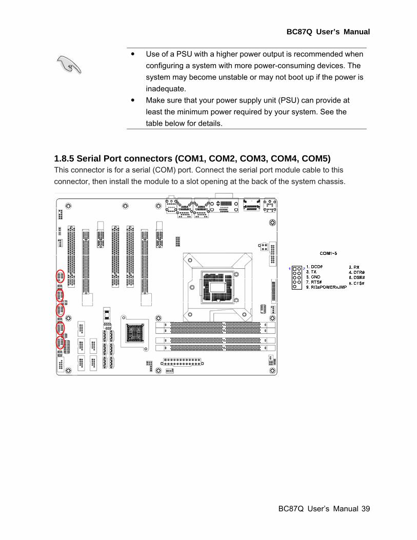
1.8.5 Serial Port connectors (COM1, COM2, COM3, COM4, COM5) This connector is for a serial (COM) port. Connect the serial port module cable to this
connector, then install the module to a slot opening at the back of the system chassis.
BC87Q User’s Manual
40 BC87Q User’s Manual
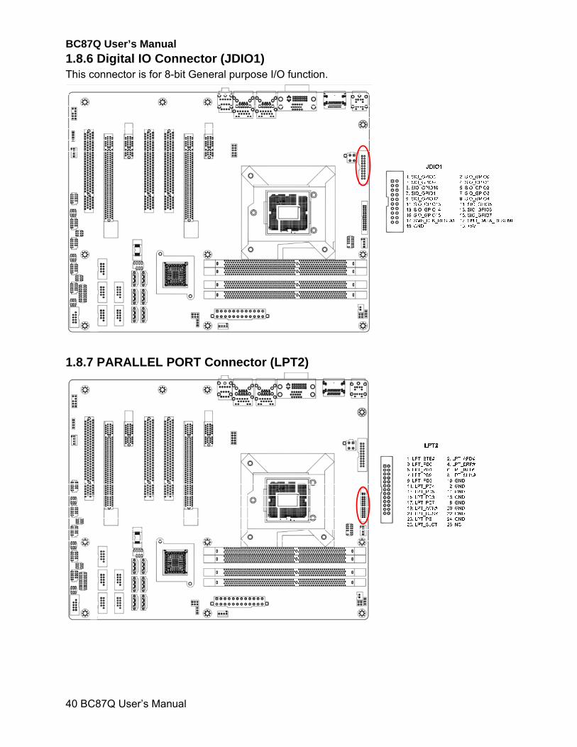
1.8.6 Digital IO Connector (JDIO1) This connector is for 8-bit General purpose I/O function.
1.8.7 PARALLEL PORT Connector (LPT2)
BC87Q User’s Manual
BC87Q User’s Manual
41
1.8.8 Audio Mic.-In & Line-Out Connector (FP_AUDIO1) This connector is for a chassis-mounted front panel audio I/O module that supports either HD
Audio or legacy AC ‘97 (optional) audio standard.
For motherboards with the optional HD Audio feature, we recommend that you connect a high-definition front panel audio module to this connector to avail of the motherboard’s high‑definition audio capability.
1.8.9 Amplifier Connector (JAMP1)
1
BC87Q User’s Manual
42 BC87Q User’s Manual
1.8.10 LAN LED Header (LANLED_1)
LANLED1
9. LAN1_SPEED_1007. GND5. LAN1_SPEED_1G 3. GND1. LAN1_ACT
10. LAN1_SPEED_1008. GND6. LAN1_SPEED_1G 4. GND2. LAN1_ACT
1.8.11 Serial ATA Connector (SATA1, SATA2, SATA3, SATA4, SATA5, SATA6) These connectors support SATA 3.0 and are for the Serial ATA signal cables for Serial ATA
hard disk drives.
BC87Q User’s Manual
BC87Q User’s Manual
43
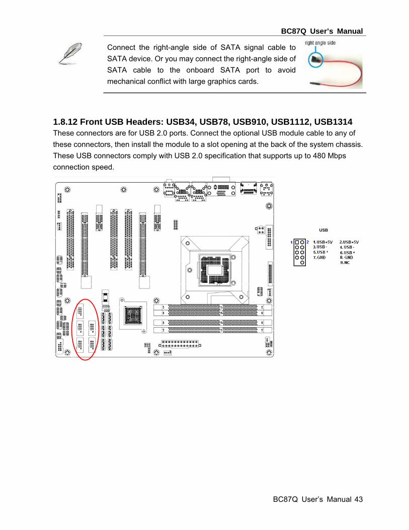
Connect the right-angle side of SATA signal cable to
SATA device. Or you may connect the right-angle side of
SATA cable to the onboard SATA port to avoid
mechanical conflict with large graphics cards.
1.8.12 Front USB Headers: USB34, USB78, USB910, USB1112, USB1314 These connectors are for USB 2.0 ports. Connect the optional USB module cable to any of
these connectors, then install the module to a slot opening at the back of the system chassis.
These USB connectors comply with USB 2.0 specification that supports up to 480 Mbps
connection speed.
USB

BC87Q User’s Manual
44 BC87Q User’s Manual
1.8.13 PC OK Connector (PC_OK1)
1.8.14 RAID LED Connector (RAID_LED1)
BC87Q User’s Manual
BC87Q User’s Manual
45
This chapter tells how to change the
system settings through the BIOS
Setup menus. Detailed descriptions
of the BIOS parameters are also
provided.
2
BC87Q User’s Manual
46 BC87Q User’s Manual
Chapter 2 - BIOS Setup
2.1 BIOS Setup Program
This motherboard supports a programmable firmware chip that you can update using the
provided utility. Use the BIOS Setup program when you are installing a motherboard,
reconfiguring your system, or prompted to “Run Setup.” This section explains how to
configure your system using this utility.
Even if you are not prompted to use the Setup program, you can change the configuration of
your computer in the future. For example, you can enable the security password feature or
change the power management settings. This requires you to reconfigure your system using
the BIOS Setup program so that the computer can recognize these changes and record them
in the CMOS RAM of the firmware hub.
The firmware hub on the motherboard stores the Setup utility. When you start up the
computer, the system provides you with the opportunity to run this program. Press <Del>
during the Power-On-Self-Test (POST) to enter the Setup utility; otherwise, POST continues
with its test routines.
If you wish to enter Setup after POST, restart the system by pressing <Ctrl+Alt+Delete>, or
by pressing the reset button on the system chassis. You can also restart by turning the
system off and then back on. Do this last option only if the first two failed.
The Setup program is designed to make it as easy to use as possible. Being a menu-driven
program, it lets you scroll through the various sub-menus and make your selections from the
available options using the navigation keys.
The default BIOS settings for this motherboard apply for most conditions to ensure optimum performance. If the system becomes unstable after changing any BIOS settings, load the default settings to ensure system compatibility and stability. Select the Load Optimized Defaults from the BIOS menu screen.
The BIOS setup screens shown in this section are for reference purposes only, and may not exactly match what you see on your screen.
Visit the system builder’s website to download the latest BIOS file for this motherboard
BC87Q User’s Manual
BC87Q User’s Manual
47
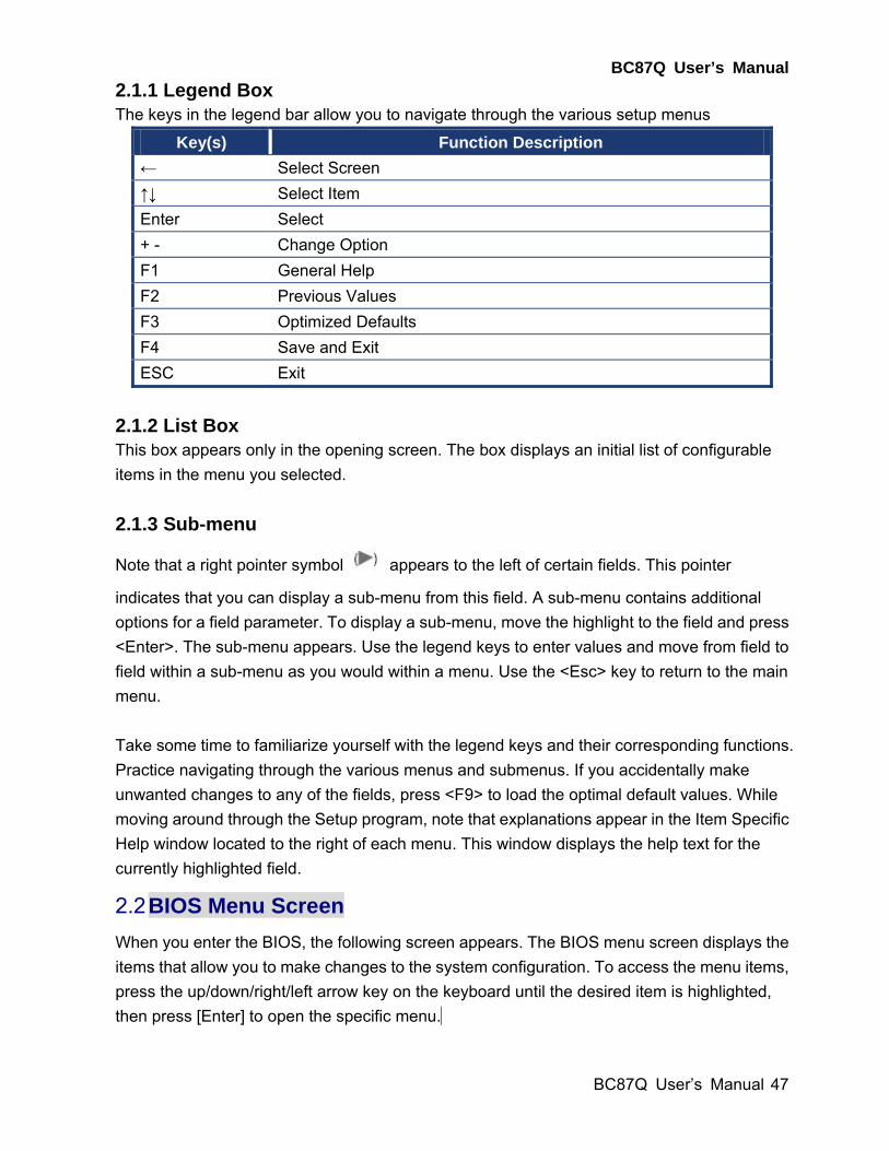
2.1.1 Legend Box The keys in the legend bar allow you to navigate through the various setup menus
Key(s) Function Description
← Select Screen
↑↓ Select Item
Enter Select
+ - Change Option
F1 General Help
F2 Previous Values
F3 Optimized Defaults
F4 Save and Exit
ESC Exit
2.1.2 List Box This box appears only in the opening screen. The box displays an initial list of configurable
items in the menu you selected.
2.1.3 Sub-menu
Note that a right pointer symbol appears to the left of certain fields. This pointer
indicates that you can display a sub-menu from this field. A sub-menu contains additional
options for a field parameter. To display a sub-menu, move the highlight to the field and press
<Enter>. The sub-menu appears. Use the legend keys to enter values and move from field to
field within a sub-menu as you would within a menu. Use the <Esc> key to return to the main
menu.
Take some time to familiarize yourself with the legend keys and their corresponding functions.
Practice navigating through the various menus and submenus. If you accidentally make
unwanted changes to any of the fields, press <F9> to load the optimal default values. While
moving around through the Setup program, note that explanations appear in the Item Specific
Help window located to the right of each menu. This window displays the help text for the
currently highlighted field.
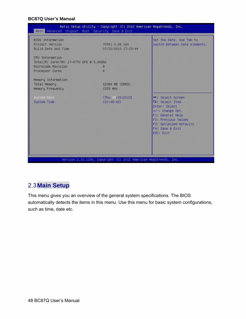
2.2 BIOS Menu Screen
When you enter the BIOS, the following screen appears. The BIOS menu screen displays the
items that allow you to make changes to the system configuration. To access the menu items,
press the up/down/right/left arrow key on the keyboard until the desired item is highlighted,
then press [Enter] to open the specific menu.
BC87Q User’s Manual
48 BC87Q User’s Manual
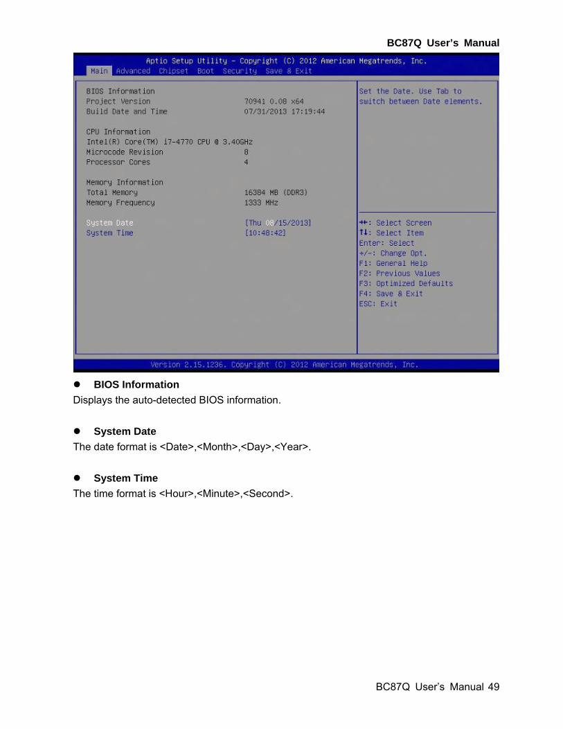
2.3 Main Setup
This menu gives you an overview of the general system specifications. The BIOS
automatically detects the items in this menu. Use this menu for basic system configurations,
such as time, date etc.
BC87Q User’s Manual
BC87Q User’s Manual
49
BIOS Information
Displays the auto-detected BIOS information.
System Date
The date format is <Date>,<Month>,<Day>,<Year>.
System Time
The time format is <Hour>,<Minute>,<Second>.
BC87Q User’s Manual
50 BC87Q User’s Manual
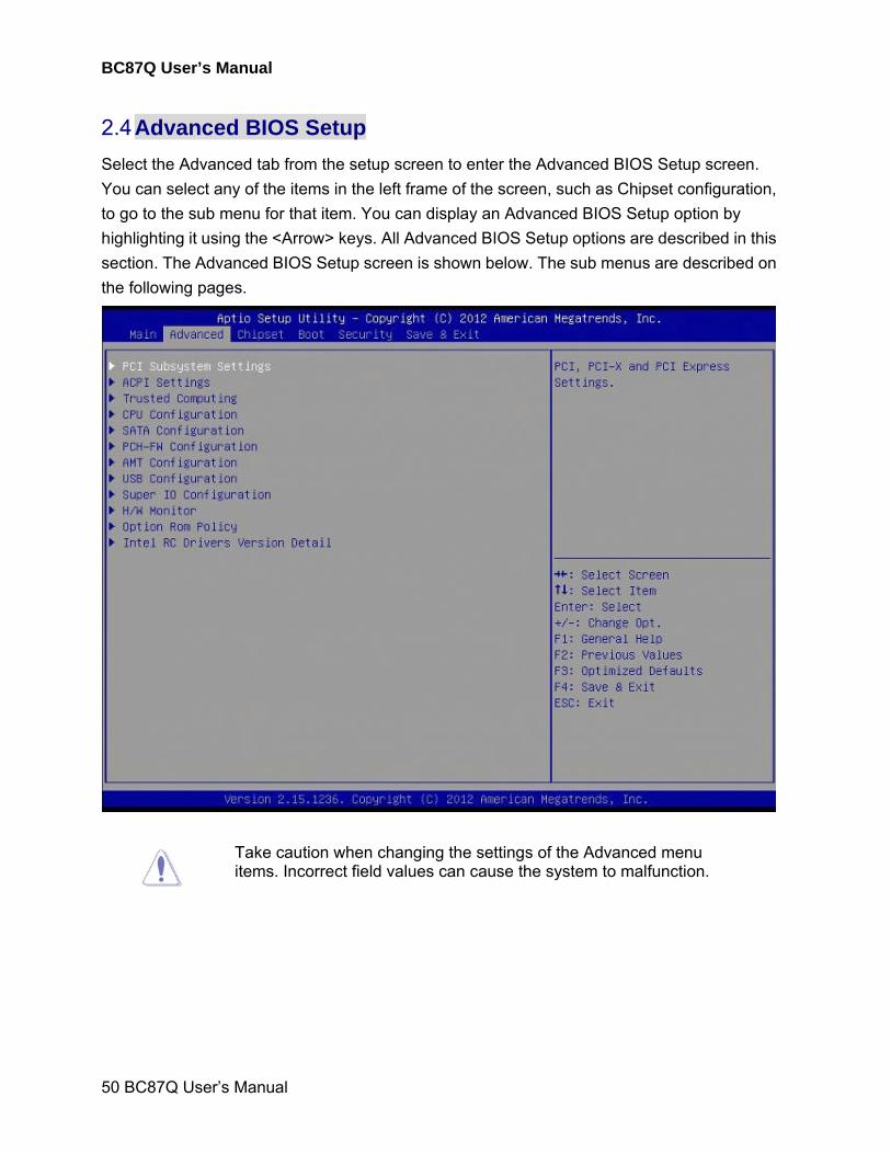
2.4 Advanced BIOS Setup
Select the Advanced tab from the setup screen to enter the Advanced BIOS Setup screen.
You can select any of the items in the left frame of the screen, such as Chipset configuration,
to go to the sub menu for that item. You can display an Advanced BIOS Setup option by
highlighting it using the <Arrow> keys. All Advanced BIOS Setup options are described in this
section. The Advanced BIOS Setup screen is shown below. The sub menus are described on
the following pages.
Take caution when changing the settings of the Advanced menu items. Incorrect field values can cause the system to malfunction.
BC87Q User’s Manual
BC87Q User’s Manual
51
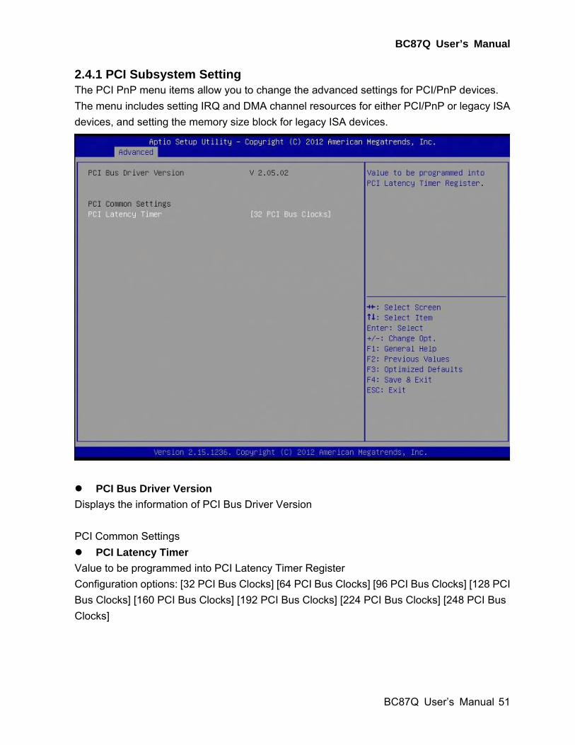
2.4.1 PCI Subsystem Setting The PCI PnP menu items allow you to change the advanced settings for PCI/PnP devices.
The menu includes setting IRQ and DMA channel resources for either PCI/PnP or legacy ISA
devices, and setting the memory size block for legacy ISA devices.
PCI Bus Driver Version
Displays the information of PCI Bus Driver Version
PCI Common Settings
PCI Latency Timer
Value to be programmed into PCI Latency Timer Register
Configuration options: [32 PCI Bus Clocks] [64 PCI Bus Clocks] [96 PCI Bus Clocks] [128 PCI
Bus Clocks] [160 PCI Bus Clocks] [192 PCI Bus Clocks] [224 PCI Bus Clocks] [248 PCI Bus
Clocks]
BC87Q User’s Manual
52 BC87Q User’s Manual
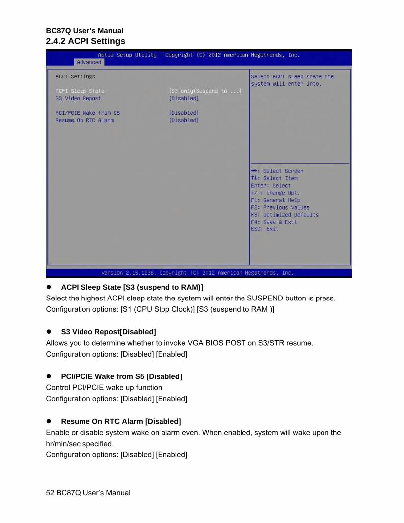
2.4.2 ACPI Settings
ACPI Sleep State [S3 (suspend to RAM)]
Select the highest ACPI sleep state the system will enter the SUSPEND button is press.
Configuration options: [S1 (CPU Stop Clock)] [S3 (suspend to RAM )]
S3 Video Repost[Disabled]
Allows you to determine whether to invoke VGA BIOS POST on S3/STR resume.
Configuration options: [Disabled] [Enabled]
PCI/PCIE Wake from S5 [Disabled]
Control PCI/PCIE wake up function
Configuration options: [Disabled] [Enabled]
Resume On RTC Alarm [Disabled]
Enable or disable system wake on alarm even. When enabled, system will wake upon the
hr/min/sec specified.
Configuration options: [Disabled] [Enabled]
BC87Q User’s Manual
BC87Q User’s Manual
53
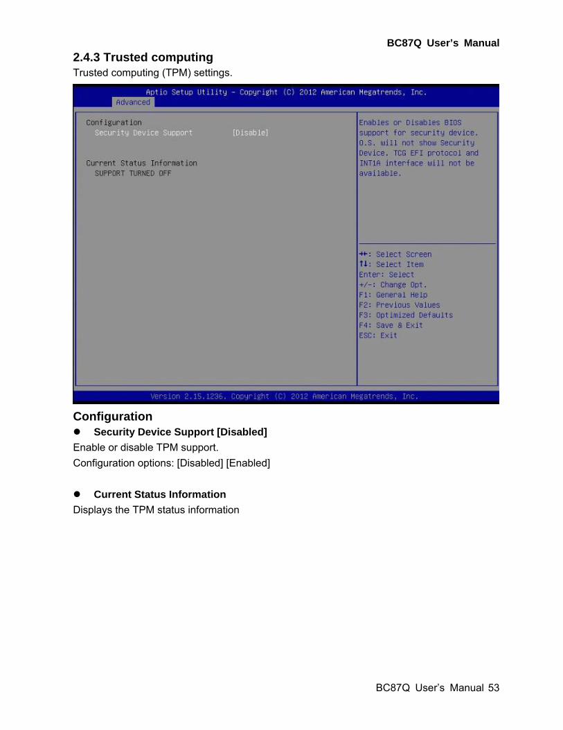
2.4.3 Trusted computing Trusted computing (TPM) settings.
Configuration Security Device Support [Disabled]
Enable or disable TPM support.
Configuration options: [Disabled] [Enabled]
Current Status Information
Displays the TPM status information
BC87Q User’s Manual
54 BC87Q User’s Manual
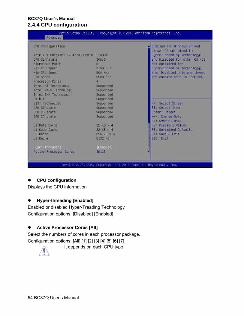
2.4.4 CPU configuration
CPU configuration
Displays the CPU information
Hyper-threading [Enabled]
Enabled or disabled Hyper-Treading Technology
Configuration options: [Disabled] [Enabled]
Active Processor Cores [All]
Select the numbers of cores in each processor package.
Configuration options: [All] [1] [2] [3] [4] [5] [6] [7]
It depends on each CPU type.
BC87Q User’s Manual
BC87Q User’s Manual
55
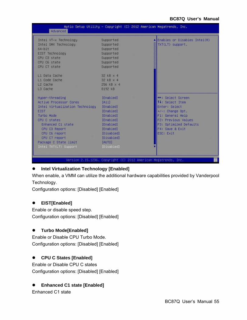
Intel Virtualization Technology [Enabled]
When enable, a VMM can utilize the additional hardware capabilities provided by Vanderpool
Technology.
Configuration options: [Disabled] [Enabled]
EIST[Enabled]
Enable or disable speed step.
Configuration options: [Disabled] [Enabled]
Turbo Mode[Enabled]
Enable or Disable CPU Turbo Mode.
Configuration options: [Disabled] [Enabled]
CPU C States [Enabled]
Enable or Disable CPU C states
Configuration options: [Disabled] [Enabled]
Enhanced C1 state [Enabled]
Enhanced C1 state
BC87Q User’s Manual
56 BC87Q User’s Manual
Configuration options: [Disabled] [Enabled]
CPU C3 State Support [Enabled]
Use this to enable or disable CPU C3 (ACPI C2) report to OS.
Configuration options: [Disabled] [Enabled]
CPU C6 State Support [Disabled]
Use this to enable or disable CPU C6 (ACPI C3) report to OS.
Configuration options: [Disabled] [Enabled]
CPU C7 State Support [Disabled]
Use this to enable or disable CPU C7 report to OS.
Configuration options: [Disabled] [Enabled]
Note: The C6/C7 power state will have a new minimum load spec of 0.05 Amps for the 12V2 rail. For
customer systems which do not use a PSU that meets Intel®’s minimum current load specifications,
Intel strongly suggests to disable the processors’ C6/C7 power states in your motherboard BIOS. When
the processor’s C6/C7 state is disabled, the next lowest power state will be C3 (Deep Sleep Mode) which
should be enabled.
Package C State limit [AUTO]
Package C State limit.
Configuration options: [C0/C1] [C2] [C3] [C6] [C7] [C7s] [AUTO]
Intel TXT(LT) Support [Disabled]
Enable or disable Intel TXT(LT) support.
Configuration options: [Disabled] [Enabled]
BC87Q User’s Manual
BC87Q User’s Manual
57
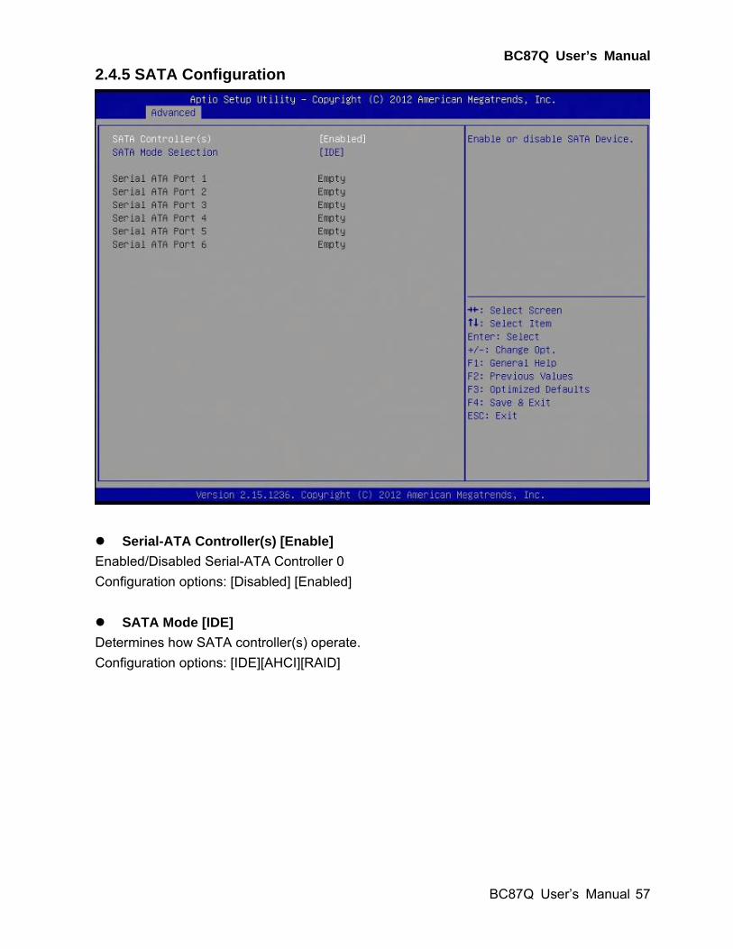
2.4.5 SATA Configuration
Serial-ATA Controller(s) [Enable]
Enabled/Disabled Serial-ATA Controller 0
Configuration options: [Disabled] [Enabled]
SATA Mode [IDE]
Determines how SATA controller(s) operate.
Configuration options: [IDE][AHCI][RAID]
BC87Q User’s Manual
58 BC87Q User’s Manual
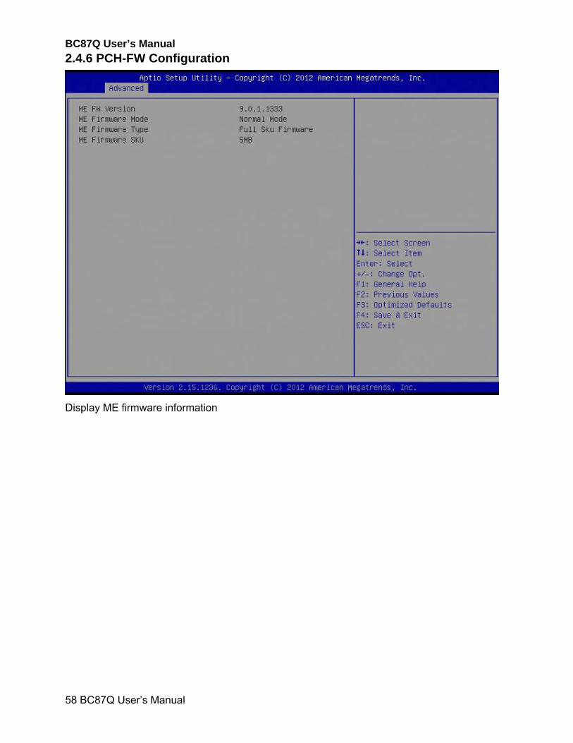
2.4.6 PCH-FW Configuration
Display ME firmware information
BC87Q User’s Manual
BC87Q User’s Manual
59
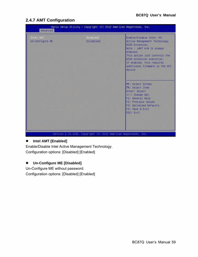
2.4.7 AMT Configuration
Intel AMT [Enabled]
Enable/Disable Intel Active Management Technology.
Configuration options: [Disabled] [Enabled]
Un-Configure ME [Disabled]
Un-Configure ME without password.
Configuration options: [Disabled] [Enabled]
BC87Q User’s Manual
60 BC87Q User’s Manual
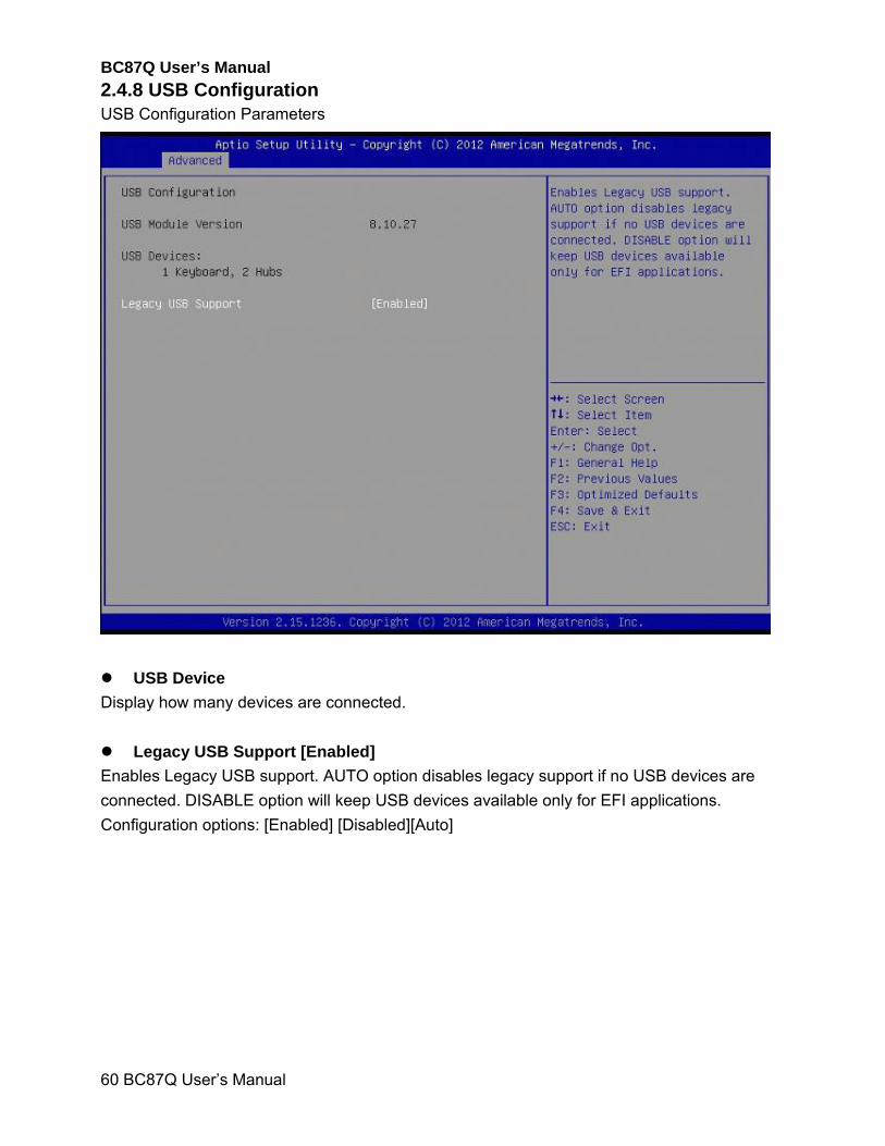
2.4.8 USB Configuration USB Configuration Parameters
USB Device
Display how many devices are connected.
Legacy USB Support [Enabled]
Enables Legacy USB support. AUTO option disables legacy support if no USB devices are
connected. DISABLE option will keep USB devices available only for EFI applications.
Configuration options: [Enabled] [Disabled][Auto]
BC87Q User’s Manual
BC87Q User’s Manual
61
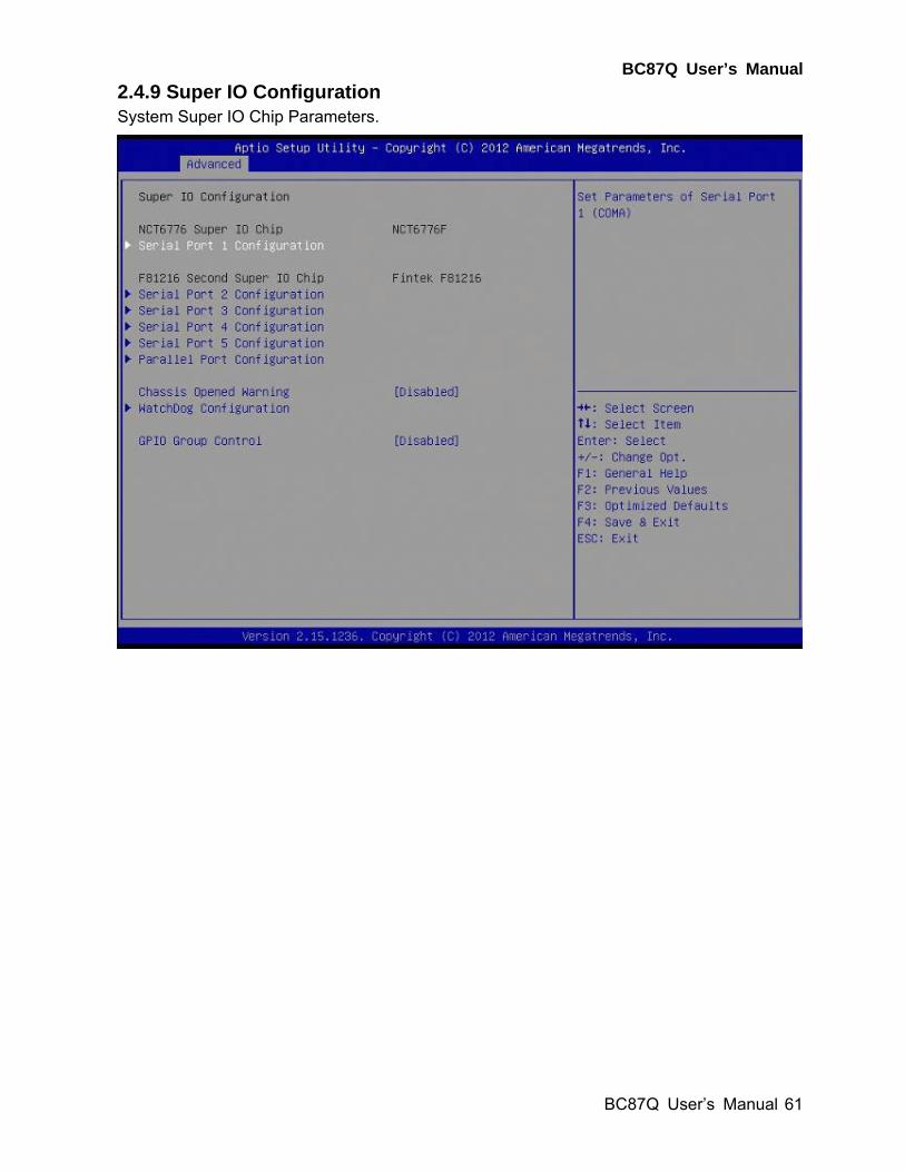
2.4.9 Super IO Configuration System Super IO Chip Parameters.
BC87Q User’s Manual
62 BC87Q User’s Manual
Super IO Configuration
NCT6776 Super IO Chip [NCT6776F]
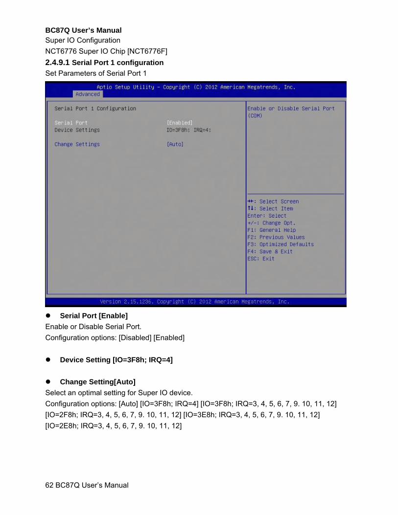
2.4.9.1 Serial Port 1 configuration
Set Parameters of Serial Port 1
Serial Port [Enable]
Enable or Disable Serial Port.
Configuration options: [Disabled] [Enabled]
Device Setting [IO=3F8h; IRQ=4]
Change Setting[Auto]
Select an optimal setting for Super IO device.
Configuration options: [Auto] [IO=3F8h; IRQ=4] [IO=3F8h; IRQ=3, 4, 5, 6, 7, 9. 10, 11, 12]
[IO=2F8h; IRQ=3, 4, 5, 6, 7, 9. 10, 11, 12] [IO=3E8h; IRQ=3, 4, 5, 6, 7, 9. 10, 11, 12]
[IO=2E8h; IRQ=3, 4, 5, 6, 7, 9. 10, 11, 12]
BC87Q User’s Manual
BC87Q User’s Manual
63
F81216 Second Super IO Chip [Fintek F81216]
2.4.9.2 Serial Port 2 configuration
Set Parameters of Serial Port 2
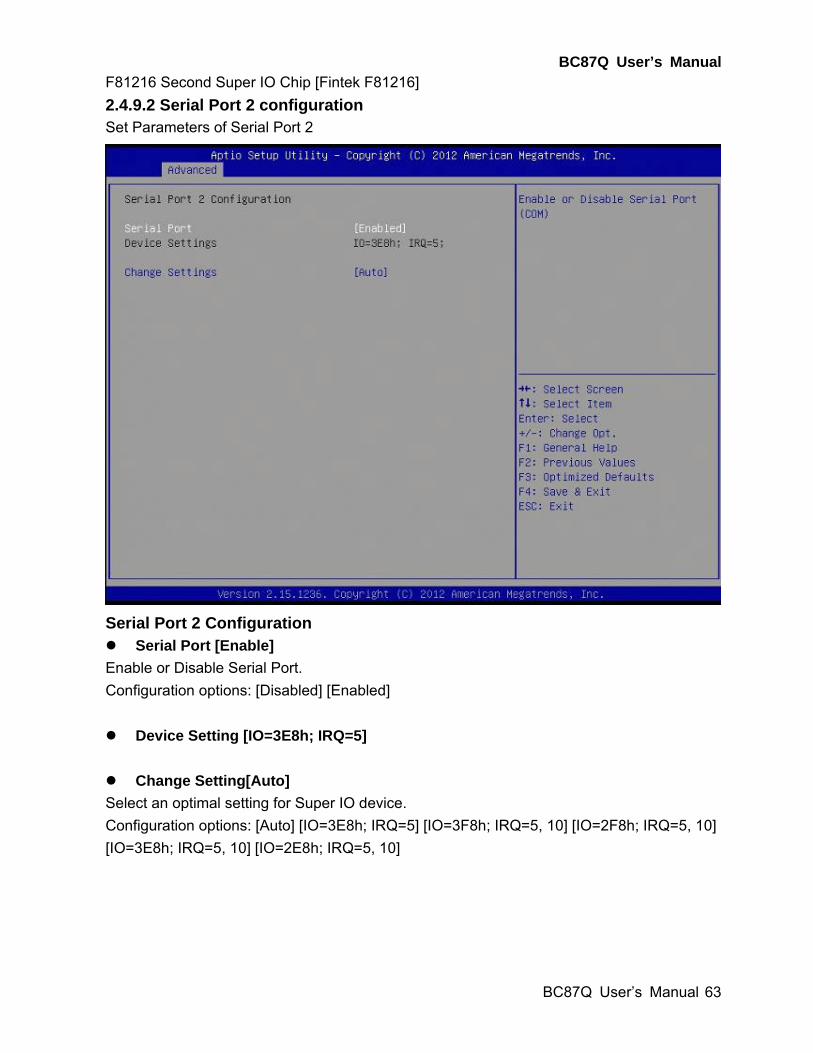
Serial Port 2 Configuration Serial Port [Enable]
Enable or Disable Serial Port.
Configuration options: [Disabled] [Enabled]
Device Setting [IO=3E8h; IRQ=5]
Change Setting[Auto]
Select an optimal setting for Super IO device.
Configuration options: [Auto] [IO=3E8h; IRQ=5] [IO=3F8h; IRQ=5, 10] [IO=2F8h; IRQ=5, 10]
[IO=3E8h; IRQ=5, 10] [IO=2E8h; IRQ=5, 10]

BC87Q User’s Manual
64 BC87Q User’s Manual
2.4.9.3 Serial Port 3 configuration
Set Parameters of Serial Port 3
Serial Port 3 Configuration
Serial Port [Enable]
Enable or Disable Serial Port.
Configuration options: [Disabled] [Enabled]
Device Setting [IO=2E8h; IRQ=5]
Change Setting[Auto]
Select an optimal setting for Super IO device.
Configuration options: [Auto] [IO=2E8h; IRQ=5] [IO=3F8h; IRQ=5, 10] [IO=2F8h; IRQ=5, 10]
[IO=3E8h; IRQ=5, 10] [IO=2E8h; IRQ=5, 10]
BC87Q User’s Manual
BC87Q User’s Manual
65
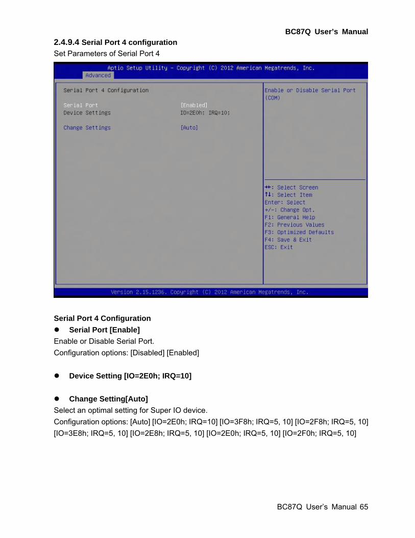
2.4.9.4 Serial Port 4 configuration
Set Parameters of Serial Port 4
Serial Port 4 Configuration
Serial Port [Enable]
Enable or Disable Serial Port.
Configuration options: [Disabled] [Enabled]
Device Setting [IO=2E0h; IRQ=10]
Change Setting[Auto]
Select an optimal setting for Super IO device.
Configuration options: [Auto] [IO=2E0h; IRQ=10] [IO=3F8h; IRQ=5, 10] [IO=2F8h; IRQ=5, 10]
[IO=3E8h; IRQ=5, 10] [IO=2E8h; IRQ=5, 10] [IO=2E0h; IRQ=5, 10] [IO=2F0h; IRQ=5, 10]
BC87Q User’s Manual
66 BC87Q User’s Manual
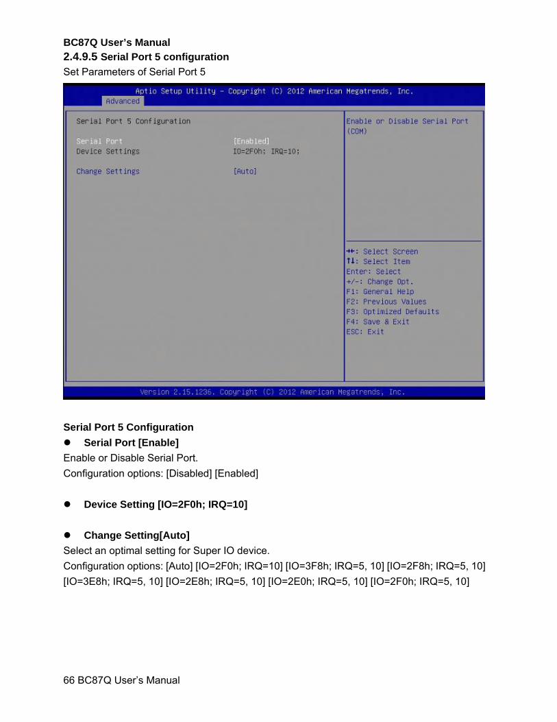
2.4.9.5 Serial Port 5 configuration
Set Parameters of Serial Port 5
Serial Port 5 Configuration
Serial Port [Enable]
Enable or Disable Serial Port.
Configuration options: [Disabled] [Enabled]
Device Setting [IO=2F0h; IRQ=10]
Change Setting[Auto]
Select an optimal setting for Super IO device.
Configuration options: [Auto] [IO=2F0h; IRQ=10] [IO=3F8h; IRQ=5, 10] [IO=2F8h; IRQ=5, 10]
[IO=3E8h; IRQ=5, 10] [IO=2E8h; IRQ=5, 10] [IO=2E0h; IRQ=5, 10] [IO=2F0h; IRQ=5, 10]
BC87Q User’s Manual
BC87Q User’s Manual
67
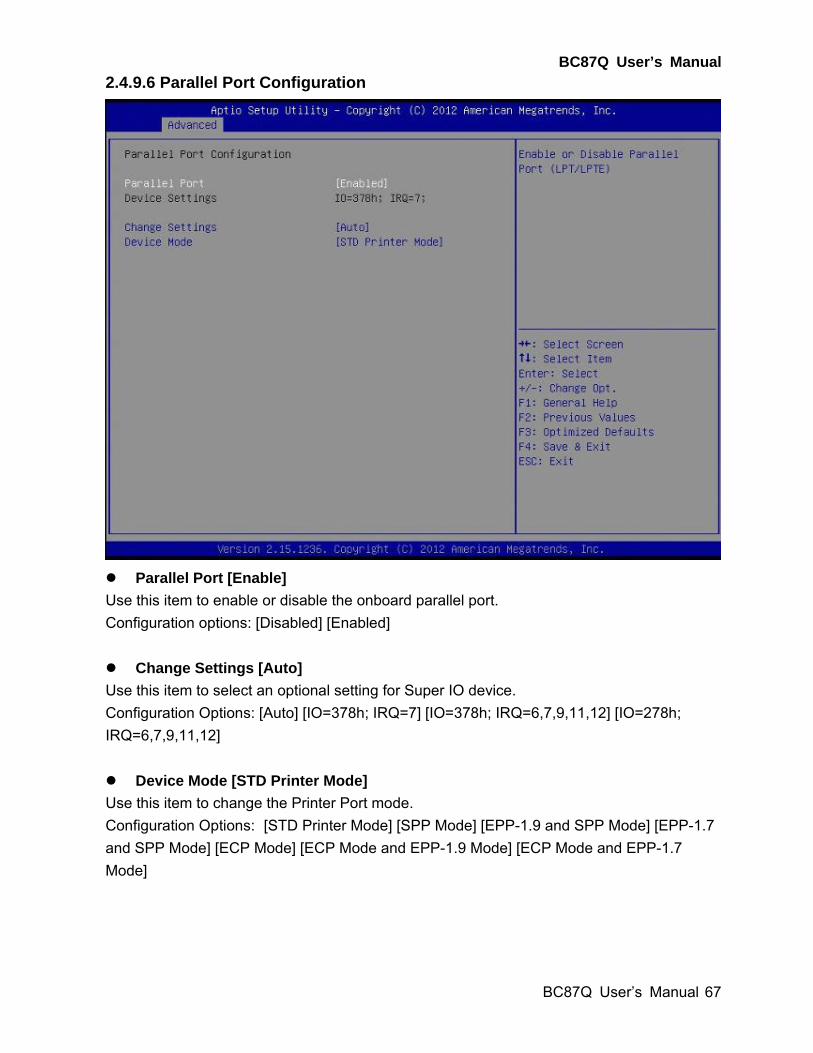
2.4.9.6 Parallel Port Configuration
Parallel Port [Enable]
Use this item to enable or disable the onboard parallel port.
Configuration options: [Disabled] [Enabled]
Change Settings [Auto]
Use this item to select an optional setting for Super IO device.
Configuration Options: [Auto] [IO=378h; IRQ=7] [IO=378h; IRQ=6,7,9,11,12] [IO=278h;
IRQ=6,7,9,11,12]
Device Mode [STD Printer Mode]
Use this item to change the Printer Port mode.
Configuration Options: [STD Printer Mode] [SPP Mode] [EPP-1.9 and SPP Mode] [EPP-1.7
and SPP Mode] [ECP Mode] [ECP Mode and EPP-1.9 Mode] [ECP Mode and EPP-1.7
Mode]
BC87Q User’s Manual
68 BC87Q User’s Manual
Chassis Opened Warning [Disabled]
Select whether to enable Chassis Intrusion Detection.
Configuration options: [Disabled] [Enabled]
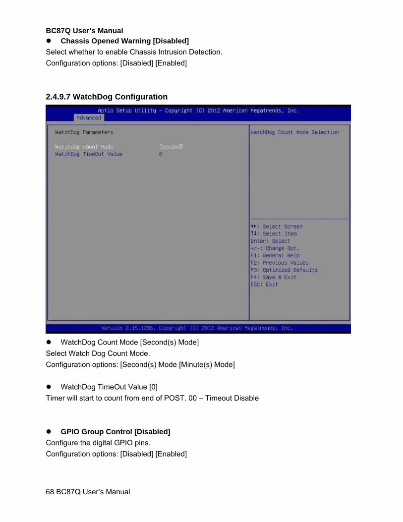
2.4.9.7 WatchDog Configuration
WatchDog Count Mode [Second(s) Mode]
Select Watch Dog Count Mode.
Configuration options: [Second(s) Mode [Minute(s) Mode]
WatchDog TimeOut Value [0]
Timer will start to count from end of POST. 00 – Timeout Disable
GPIO Group Control [Disabled]
Configure the digital GPIO pins.
Configuration options: [Disabled] [Enabled]
BC87Q User’s Manual
BC87Q User’s Manual
69
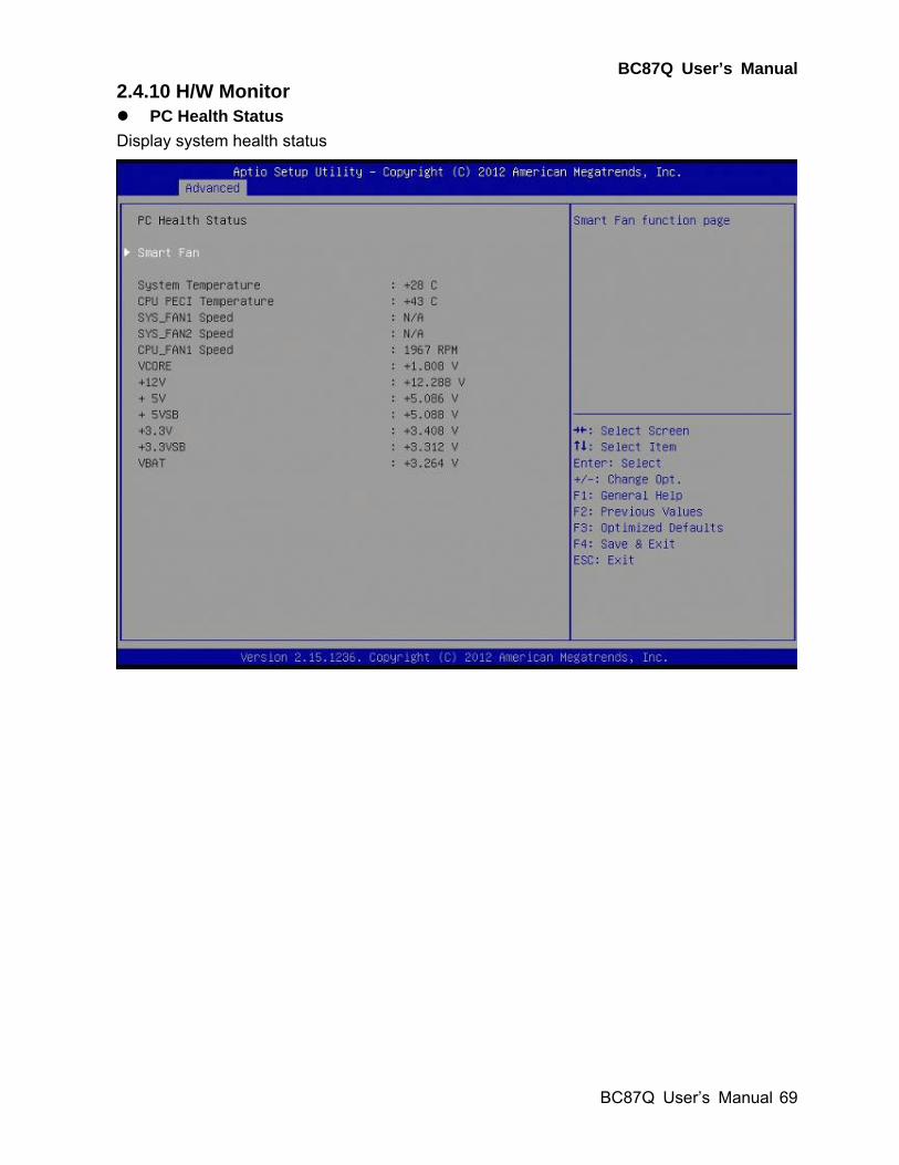
2.4.10 H/W Monitor PC Health Status
Display system health status
BC87Q User’s Manual
70 BC87Q User’s Manual
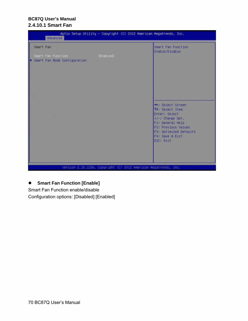
2.4.10.1 Smart Fan
Smart Fan Function [Enable]
Smart Fan Function enable/disable
Configuration options: [Disabled] [Enabled]
BC87Q User’s Manual
BC87Q User’s Manual
71
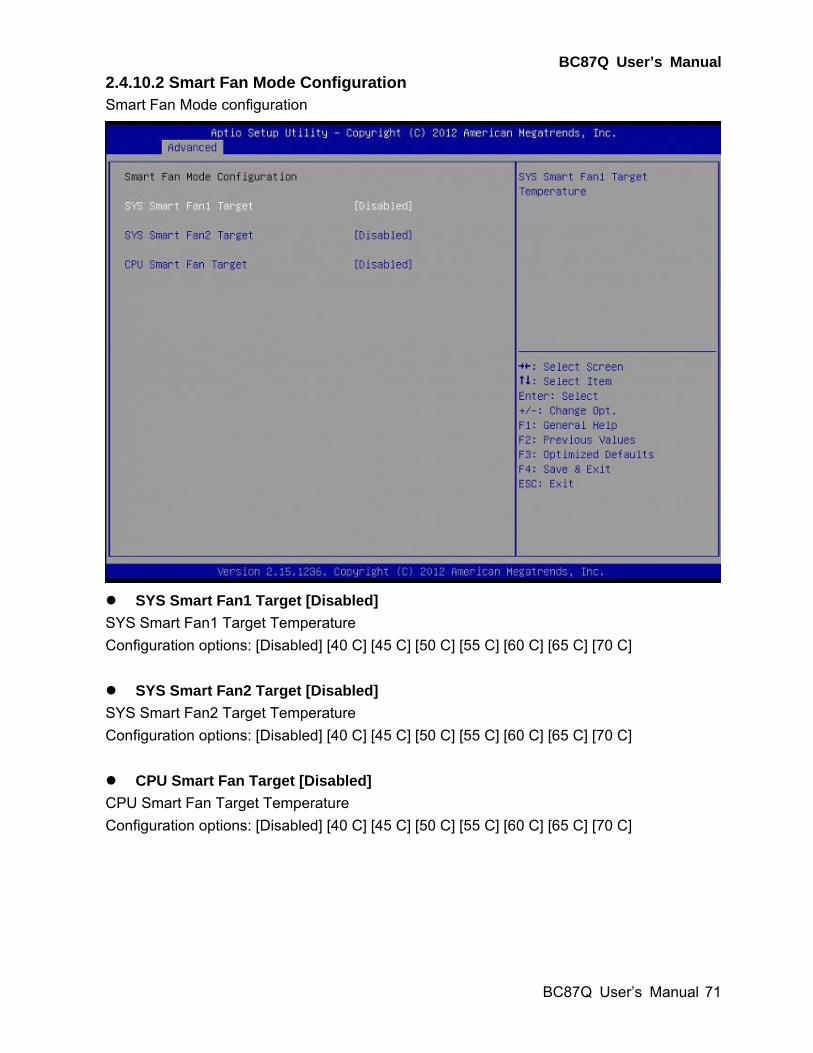
2.4.10.2 Smart Fan Mode Configuration Smart Fan Mode configuration
SYS Smart Fan1 Target [Disabled]
SYS Smart Fan1 Target Temperature
Configuration options: [Disabled] [40 C] [45 C] [50 C] [55 C] [60 C] [65 C] [70 C]
SYS Smart Fan2 Target [Disabled]
SYS Smart Fan2 Target Temperature
Configuration options: [Disabled] [40 C] [45 C] [50 C] [55 C] [60 C] [65 C] [70 C]
CPU Smart Fan Target [Disabled]
CPU Smart Fan Target Temperature
Configuration options: [Disabled] [40 C] [45 C] [50 C] [55 C] [60 C] [65 C] [70 C]
BC87Q User’s Manual
72 BC87Q User’s Manual
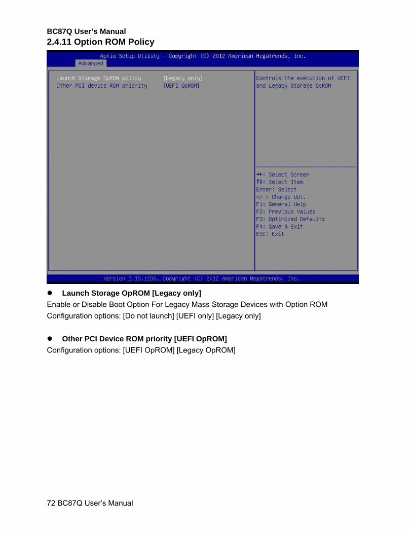
2.4.11 Option ROM Policy
Launch Storage OpROM [Legacy only]
Enable or Disable Boot Option For Legacy Mass Storage Devices with Option ROM
Configuration options: [Do not launch] [UEFI only] [Legacy only]
Other PCI Device ROM priority [UEFI OpROM]
Configuration options: [UEFI OpROM] [Legacy OpROM]
BC87Q User’s Manual
BC87Q User’s Manual
73
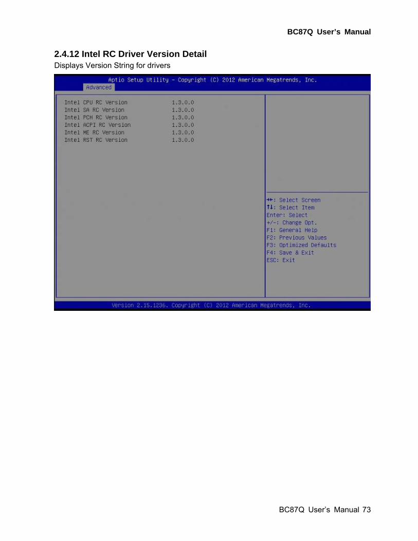
2.4.12 Intel RC Driver Version Detail Displays Version String for drivers
BC87Q User’s Manual
74 BC87Q User’s Manual
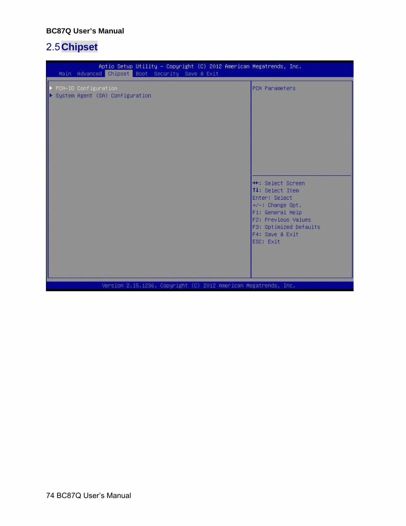
2.5 Chipset
BC87Q User’s Manual
BC87Q User’s Manual
75
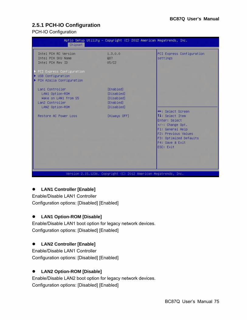
2.5.1 PCH-IO Configuration PCH-IO Configuration
LAN1 Controller [Enable]
Enable/Disable LAN1 Controller
Configuration options: [Disabled] [Enabled]
LAN1 Option-ROM [Disable]
Enable/Disable LAN1 boot option for legacy network devices.
Configuration options: [Disabled] [Enabled]
LAN2 Controller [Enable]
Enable/Disable LAN1 Controller
Configuration options: [Disabled] [Enabled]
LAN2 Option-ROM [Disable]
Enable/Disable LAN2 boot option for legacy network devices.
Configuration options: [Disabled] [Enabled]

BC87Q User’s Manual
76 BC87Q User’s Manual
Restore AC Power Loss [Always Off]
Specify what state to go to when power is re-applied after a power failure.
Configuration options: [Always Off] [Always On] [Last state]
BC87Q User’s Manual
BC87Q User’s Manual
77
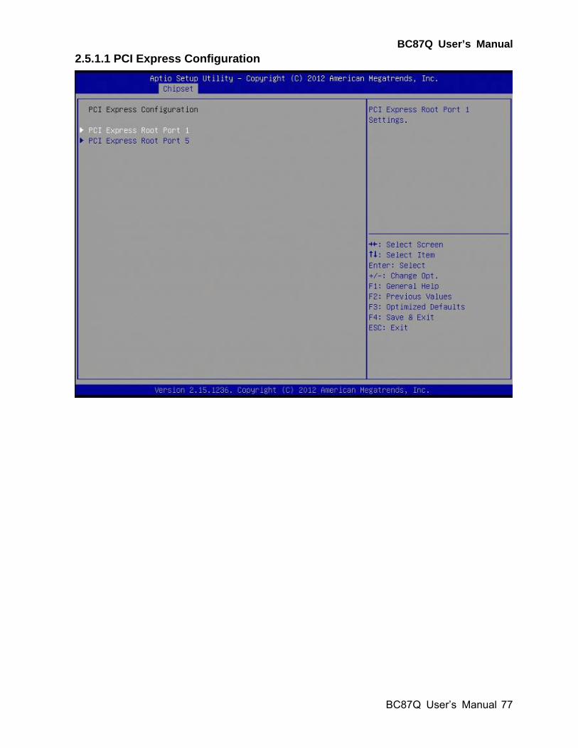
2.5.1.1 PCI Express Configuration
BC87Q User’s Manual
78 BC87Q User’s Manual
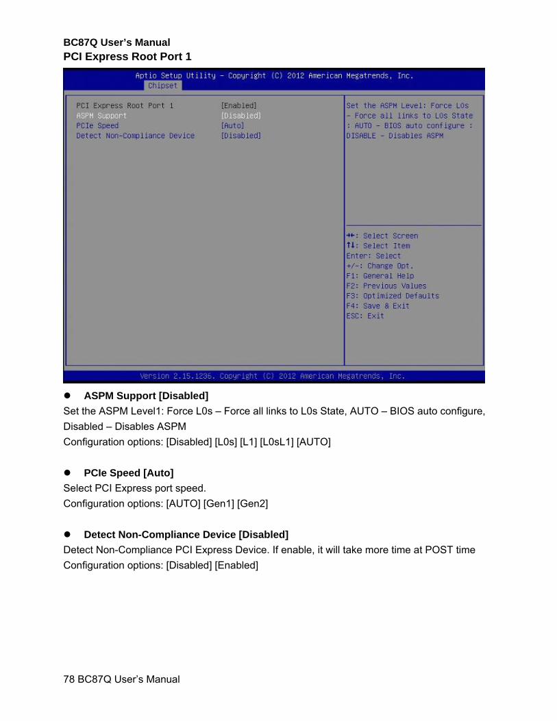
PCI Express Root Port 1
ASPM Support [Disabled]
Set the ASPM Level1: Force L0s – Force all links to L0s State, AUTO – BIOS auto configure,
Disabled – Disables ASPM
Configuration options: [Disabled] [L0s] [L1] [L0sL1] [AUTO]
PCIe Speed [Auto]
Select PCI Express port speed.
Configuration options: [AUTO] [Gen1] [Gen2]
Detect Non-Compliance Device [Disabled]
Detect Non-Compliance PCI Express Device. If enable, it will take more time at POST time
Configuration options: [Disabled] [Enabled]
BC87Q User’s Manual
BC87Q User’s Manual
79
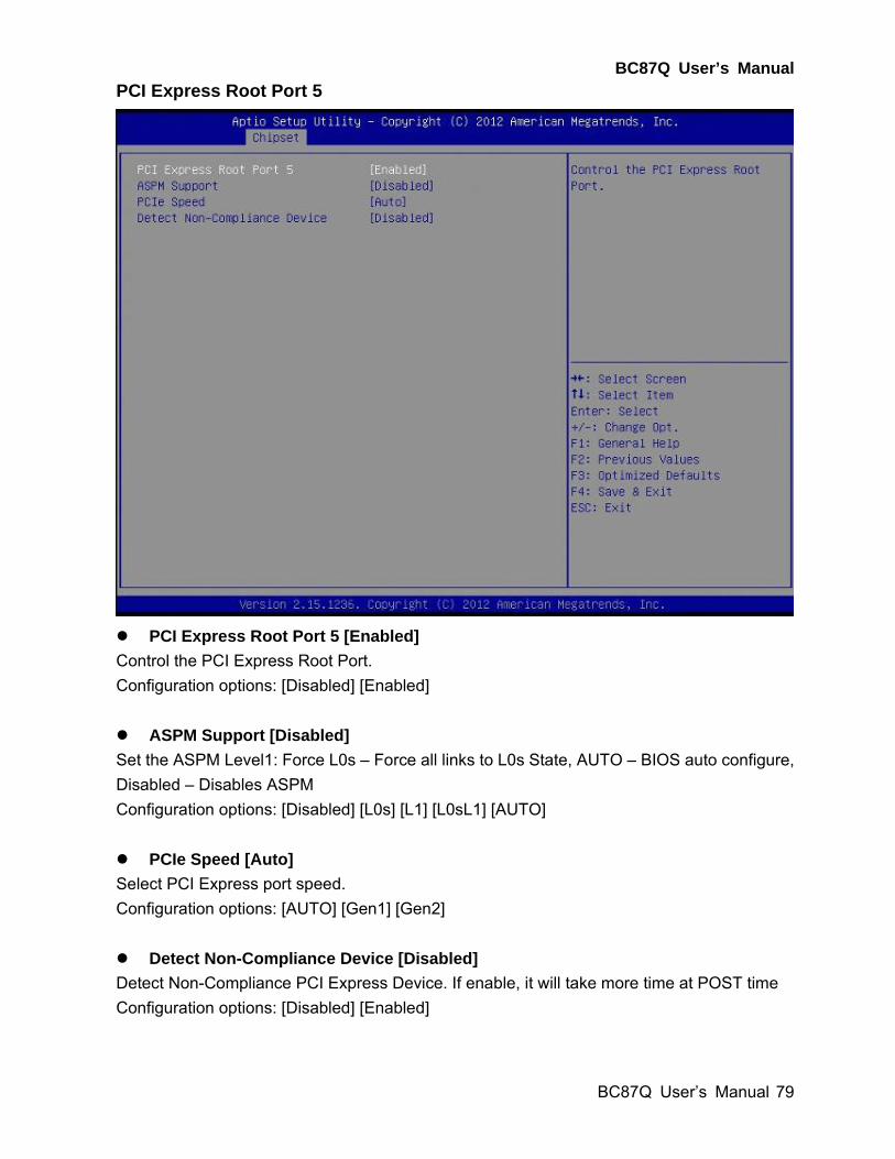
PCI Express Root Port 5
PCI Express Root Port 5 [Enabled]
Control the PCI Express Root Port.
Configuration options: [Disabled] [Enabled]
ASPM Support [Disabled]
Set the ASPM Level1: Force L0s – Force all links to L0s State, AUTO – BIOS auto configure,
Disabled – Disables ASPM
Configuration options: [Disabled] [L0s] [L1] [L0sL1] [AUTO]
PCIe Speed [Auto]
Select PCI Express port speed.
Configuration options: [AUTO] [Gen1] [Gen2]
Detect Non-Compliance Device [Disabled]
Detect Non-Compliance PCI Express Device. If enable, it will take more time at POST time
Configuration options: [Disabled] [Enabled]
BC87Q User’s Manual
80 BC87Q User’s Manual
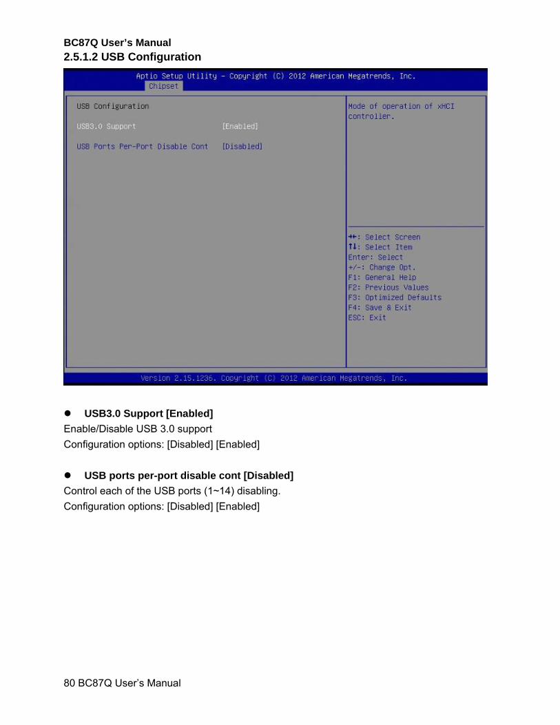
2.5.1.2 USB Configuration
USB3.0 Support [Enabled]
Enable/Disable USB 3.0 support
Configuration options: [Disabled] [Enabled]
USB ports per-port disable cont [Disabled]
Control each of the USB ports (1~14) disabling.
Configuration options: [Disabled] [Enabled]
BC87Q User’s Manual
BC87Q User’s Manual
81
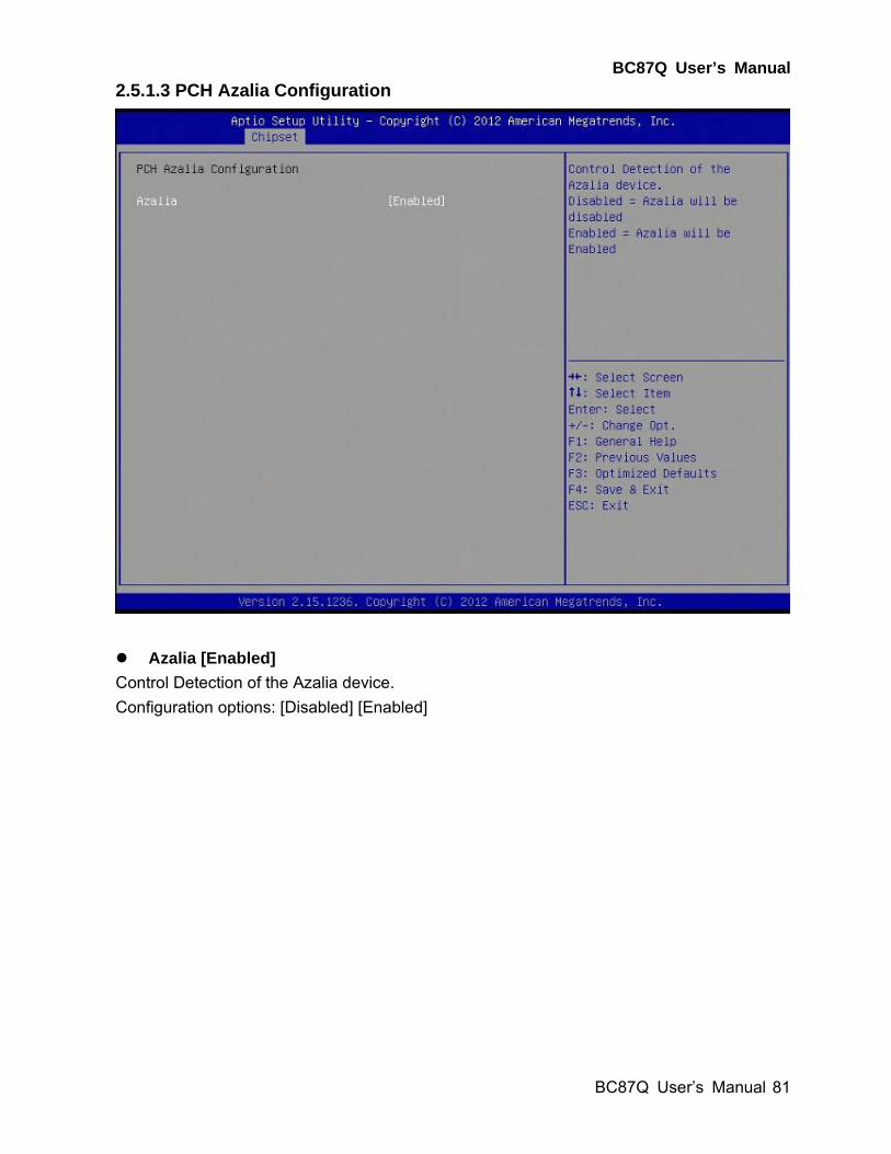
2.5.1.3 PCH Azalia Configuration
Azalia [Enabled]
Control Detection of the Azalia device.
Configuration options: [Disabled] [Enabled]
BC87Q User’s Manual
82 BC87Q User’s Manual
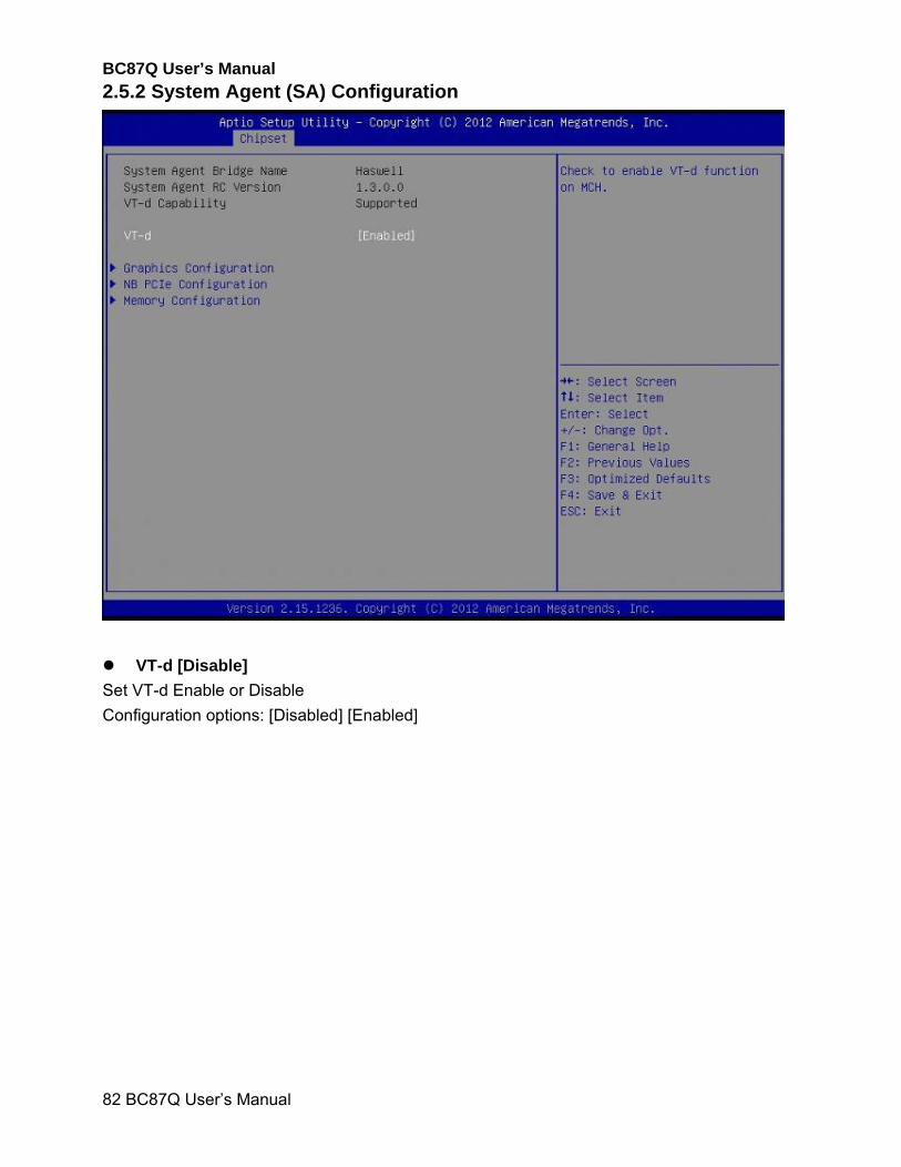
2.5.2 System Agent (SA) Configuration
VT-d [Disable]
Set VT-d Enable or Disable
Configuration options: [Disabled] [Enabled]
BC87Q User’s Manual
BC87Q User’s Manual
83
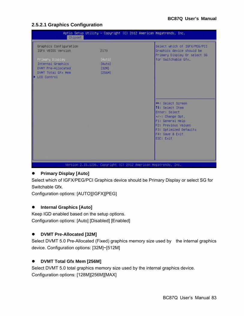
2.5.2.1 Graphics Configuration
Primary Display [Auto]
Select which of IGFX/PEG/PCI Graphics device should be Primary Display or select SG for
Switchable Gfx.
Configuration options: [AUTO][IGFX][PEG]
Internal Graphics [Auto]
Keep IGD enabled based on the setup options.
Configuration options: [Auto] [Disabled] [Enabled]
DVMT Pre-Allocated [32M]
Select DVMT 5.0 Pre-Allocated (Fixed) graphics memory size used by the internal graphics
device. Configuration options: [32M]~[512M]
DVMT Total Gfx Mem [256M]
Select DVMT 5.0 total graphics memory size used by the internal graphics device.
Configuration options: [128M][256M][MAX]
BC87Q User’s Manual
84 BC87Q User’s Manual
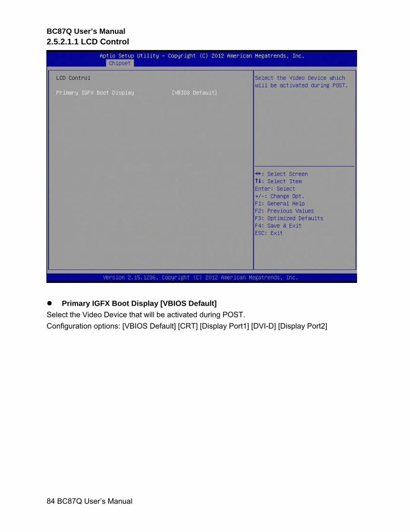
2.5.2.1.1 LCD Control
Primary IGFX Boot Display [VBIOS Default]
Select the Video Device that will be activated during POST.
Configuration options: [VBIOS Default] [CRT] [Display Port1] [DVI-D] [Display Port2]
BC87Q User’s Manual
BC87Q User’s Manual
85
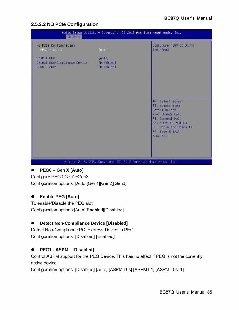
2.5.2.2 NB PCIe Configuration
PEG0 – Gen X [Auto]
Configure PEG0 Gen1~Gen3
Configuration options: [Auto][Gen1][Gen2][Gen3]
Enable PEG [Auto]
To enable/Disable the PEG slot.
Configuration options:[Auto][Enabled][Disabled]
Detect Non-Compliance Device [Disabled]
Detect Non-Compliance PCI Express Device in PEG.
Configuration options: [Disabled] [Enabled]
PEG1 - ASPM [Disabled]
Control ASPM support for the PEG Device. This has no effect if PEG is not the currently
active device.
Configuration options: [Disabled] [Auto] [ASPM L0s] [ASPM L1] [ASPM L0sL1]
BC87Q User’s Manual
86 BC87Q User’s Manual
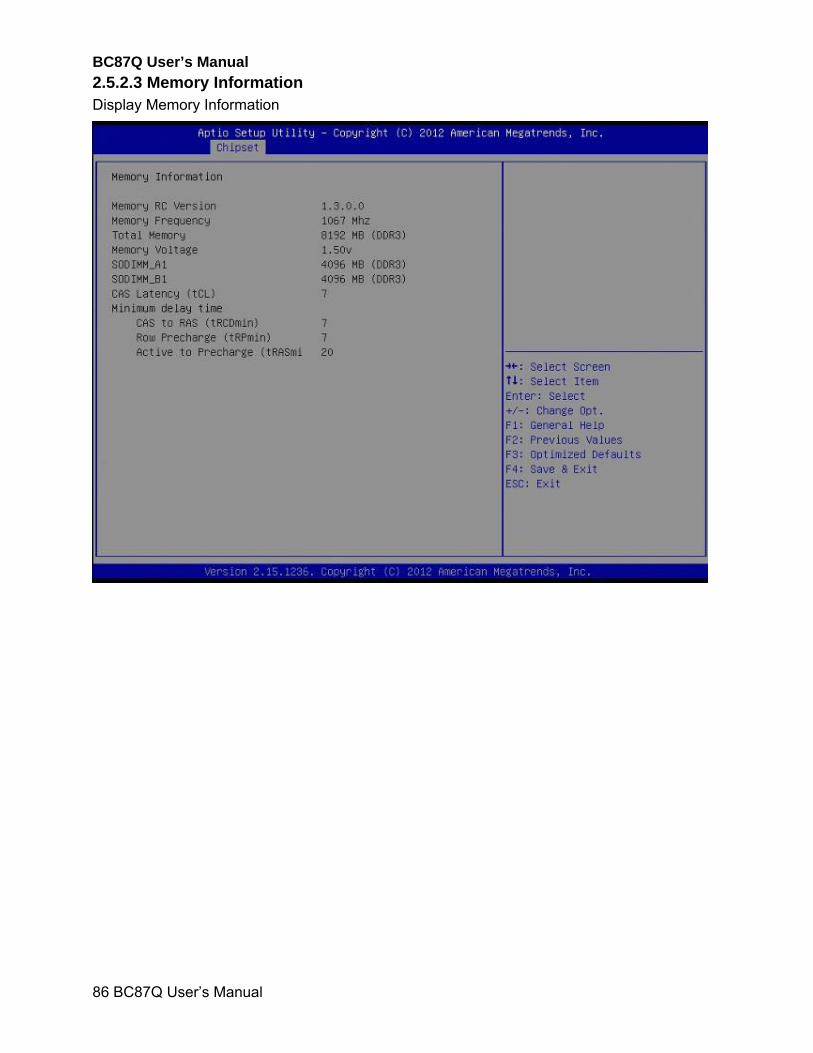
2.5.2.3 Memory Information Display Memory Information
BC87Q User’s Manual
BC87Q User’s Manual
87
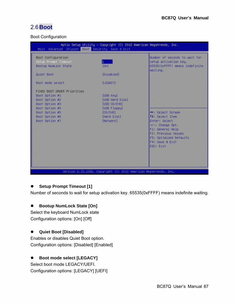
2.6 Boot
Boot Configuration
Setup Prompt Timeout [1]
Number of seconds to wait for setup activation key. 65535(0xFFFF) means indefinite waiting.
Bootup NumLock State [On]
Select the keyboard NumLock state
Configuration options: [On] [Off]
Quiet Boot [Disabled]
Enables or disables Quiet Boot option.
Configuration options: [Disabled] [Enabled]
Boot mode select [LEGACY]
Select boot mode LEGACY/UEFI.
Configuration options: [LEGACY] [UEFI]
BC87Q User’s Manual
88 BC87Q User’s Manual
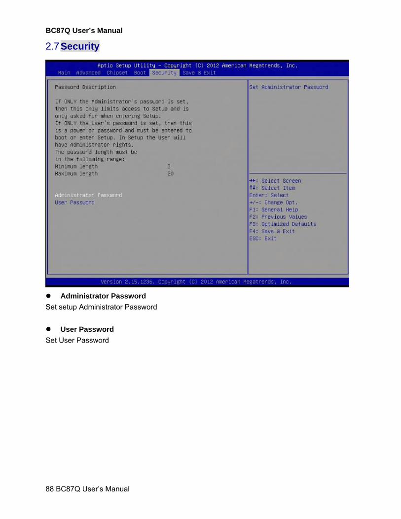
2.7 Security
Administrator Password
Set setup Administrator Password
User Password
Set User Password
BC87Q User’s Manual
BC87Q User’s Manual
89
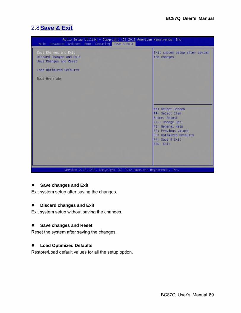
2.8 Save & Exit
Save changes and Exit
Exit system setup after saving the changes.
Discard changes and Exit
Exit system setup without saving the changes.
Save changes and Reset
Reset the system after saving the changes.
Load Optimized Defaults
Restore/Load default values for all the setup option.