Embed Size (px)
Citation preview
Overview
1 - Top / Bottom bracket mounting point x 42 - 6#32 thumbscrew x 43 - Hard drive slot x 24 - Pushpin standoff x 45 - Threaded standoff x 46 - Main body
7 - Feet thumbscrew mounting hole x 48 - Integrated carry handle9 - PCI thumbscrew x 210 - Feet x 211 - Left / Right bracket mounting point x 412 - Kensington lock13 - Bracket x 414 - M3 thumbscrew x 4
Introduction to the screws & bracket
The BC1 Mini is supplied with 5 different types of screw which are used to mount all the various hardware to the table. All screw threads are M3 except for the 6#32 thumbscrews which are used to attach PSUs.
The differences between the M3 and 6#32 thumbscrews thread is subtle, so ensure the correct one is used to avoid damage to your BC1 Mini. They also feature an inner thread on the head of the screw which allows for M3 screws to be screwed onto the thumbscrews, giving additional stacked mounting options.
The BC1 Mini brackets are used to fix additional components to the main body and feature a thick and thin side which are interchangeable and designed to accommodate different lengths of screw and thread depth on the hardware being fitted.
Note that all the screws feature a thin plastic washer at the base to ensure there is minimal damage to the aluminium surface at the point of contact. The PCI thumbscrews are packed with extra washers which should be used between the brackets and main body to minimise damage.
1
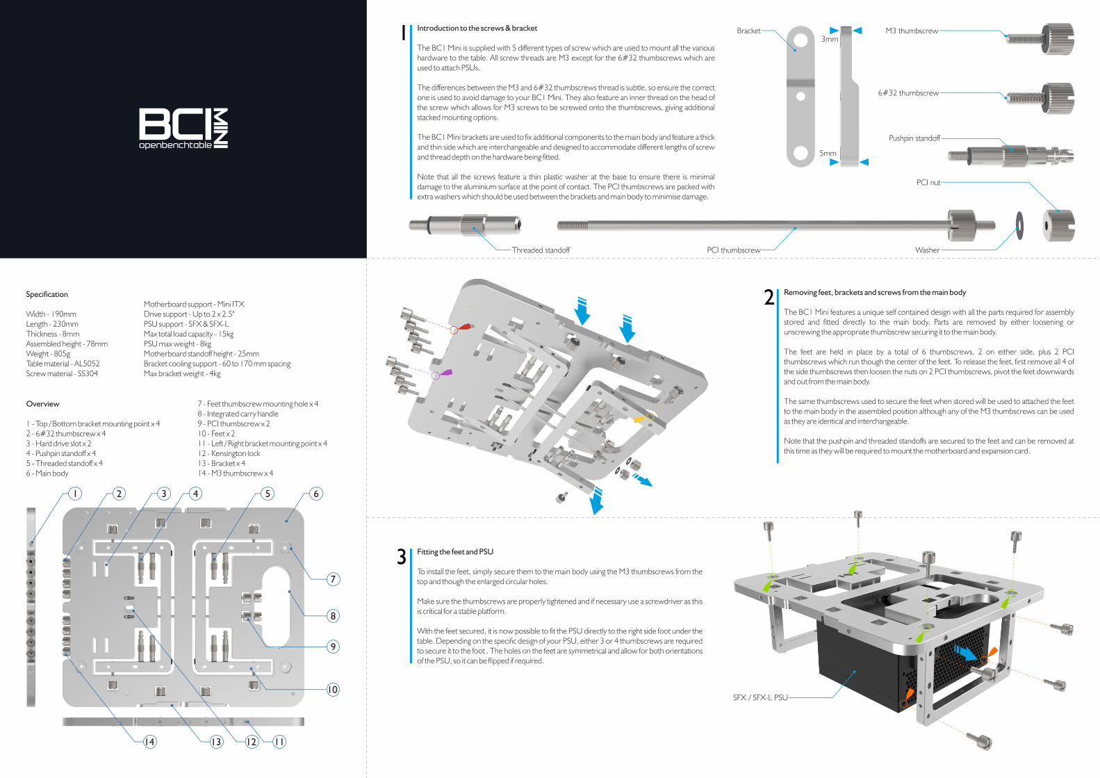
Removing feet, brackets and screws from the main body
The BC1 Mini features a unique self contained design with all the parts required for assembly stored and fitted directly to the main body. Parts are removed by either loosening or unscrewing the appropriate thumbscrew securing it to the main body.
The feet are held in place by a total of 6 thumbscrews, 2 on either side, plus 2 PCI thumbscrews which run though the center of the feet. To release the feet, first remove all 4 of the side thumbscrews then loosen the nuts on 2 PCI thumbscrews, pivot the feet downwards and out from the main body.
The same thumbscrews used to secure the feet when stored will be used to attached the feet to the main body in the assembled position although any of the M3 thumbscrews can be used as they are identical and interchangeable.
Note that the pushpin and threaded standoffs are secured to the feet and can be removed at this time as they will be required to mount the motherboard and expansion card.
2
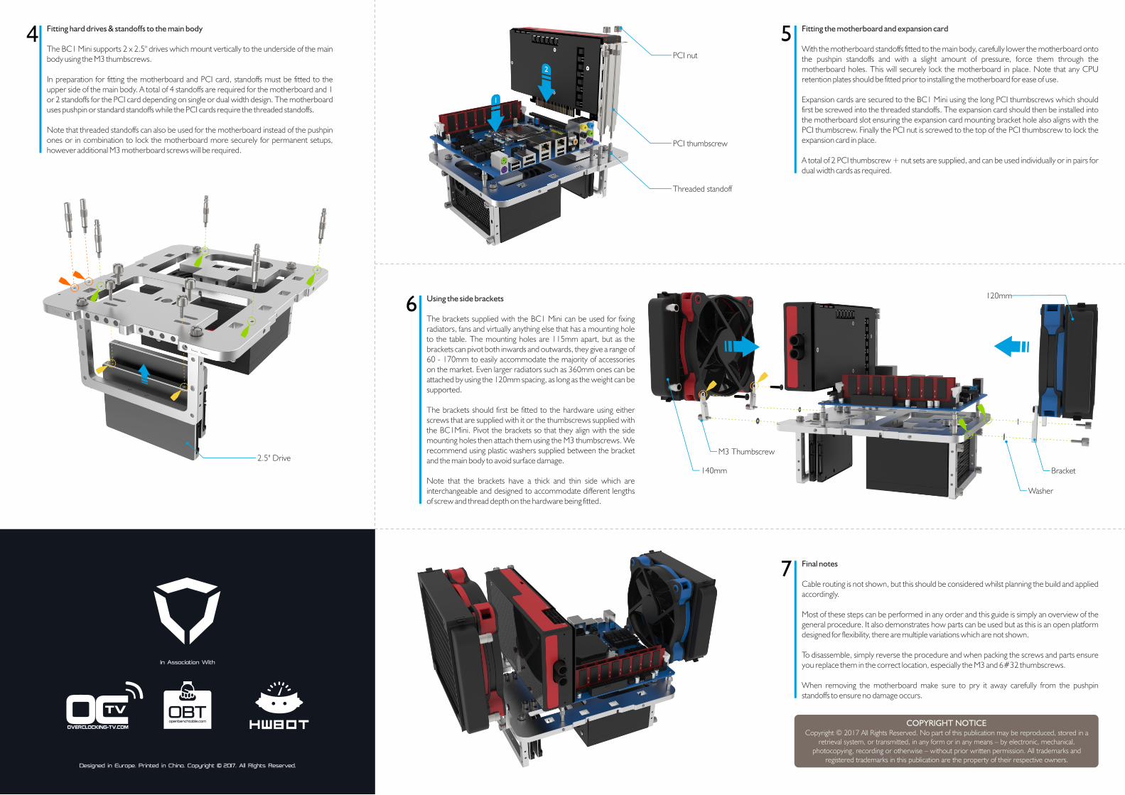
Fitting the feet and PSU
To install the feet, simply secure them to the main body using the M3 thumbscrews from the top and though the enlarged circular holes.
Make sure the thumbscrews are properly tightened and if necessary use a screwdriver as this is critical for a stable platform.
With the feet secured, it is now possible to fit the PSU directly to the right side foot under the table. Depending on the specific design of your PSU, either 3 or 4 thumbscrews are required to secure it to the foot . The holes on the feet are symmetrical and allow for both orientations of the PSU, so it can be flipped if required.
3
9
7
8
10
11
M3 thumbscrew
Threaded standoff
1
SFX / SFX-L PSU
Specification
Width - 190mmLength - 230mmThickness - 8mmAssembled height - 78mmWeight - 805gTable material - AL5052Screw material - SS304
Motherboard support - Mini ITXDrive support - Up to 2 x 2.5"PSU support - SFX & SFX-LMax total load capacity - 15kgPSU max weight - 8kgMotherboard standoff height - 25mmBracket cooling support - 60 to 170 mm spacingMax bracket weight - 4kg
2 3 4 5 6
1314 12
6#32 thumbscrew
Pushpin standoff
PCI nut
WasherPCI thumbscrew
Bracket
5mm
3mm
Fitting hard drives & standoffs to the main body
The BC1 Mini supports 2 x 2.5" drives which mount vertically to the underside of the main body using the M3 thumbscrews.
In preparation for fitting the motherboard and PCI card, standoffs must be fitted to the upper side of the main body. A total of 4 standoffs are required for the motherboard and 1 or 2 standoffs for the PCI card depending on single or dual width design. The motherboard uses pushpin or standard standoffs while the PCI cards require the threaded standoffs.
Note that threaded standoffs can also be used for the motherboard instead of the pushpin ones or in combination to lock the motherboard more securely for permanent setups, however additional M3 motherboard screws will be required.
4 Fitting the motherboard and expansion card
With the motherboard standoffs fitted to the main body, carefully lower the motherboard onto the pushpin standoffs and with a slight amount of pressure, force them through the motherboard holes. This will securely lock the motherboard in place. Note that any CPU retention plates should be fitted prior to installing the motherboard for ease of use.
Expansion cards are secured to the BC1 Mini using the long PCI thumbscrews which should first be screwed into the threaded standoffs. The expansion card should then be installed into the motherboard slot ensuring the expansion card mounting bracket hole also aligns with the PCI thumbscrew. Finally the PCI nut is screwed to the top of the PCI thumbscrew to lock the expansion card in place.
A total of 2 PCI thumbscrew + nut sets are supplied, and can be used individually or in pairs for dual width cards as required.
5
Using the side brackets
The brackets supplied with the BC1 Mini can be used for fixing radiators, fans and virtually anything else that has a mounting hole to the table. The mounting holes are 115mm apart, but as the brackets can pivot both inwards and outwards, they give a range of 60 - 170mm to easily accommodate the majority of accessories on the market. Even larger radiators such as 360mm ones can be attached by using the 120mm spacing, as long as the weight can be supported.
The brackets should first be fitted to the hardware using either screws that are supplied with it or the thumbscrews supplied with the BC1Mini. Pivot the brackets so that they align with the side mounting holes then attach them using the M3 thumbscrews. We recommend using plastic washers supplied between the bracket and the main body to avoid surface damage.
Note that the brackets have a thick and thin side which are interchangeable and designed to accommodate different lengths of screw and thread depth on the hardware being fitted.
6
Final notes
Cable routing is not shown, but this should be considered whilst planning the build and applied accordingly.
Most of these steps can be performed in any order and this guide is simply an overview of the general procedure. It also demonstrates how parts can be used but as this is an open platform designed for flexibility, there are multiple variations which are not shown.
To disassemble, simply reverse the procedure and when packing the screws and parts ensure you replace them in the correct location, especially the M3 and 6#32 thumbscrews.
When removing the motherboard make sure to pry it away carefully from the pushpin standoffs to ensure no damage occurs.
7
Designed in Europe. Printed in China. Copyright © 2017. All Rights Reserved.
In Association With
2.5" Drive
Threaded standoff
PCI thumbscrew
PCI nut
1
2
Important Notice
COPYRIGHT NOTICECopyright © 2017 All Rights Reserved. No part of this publication may be reproduced, stored in a
retrieval system, or transmitted, in any form or in any means – by electronic, mechanical, photocopying, recording or otherwise – without prior written permission. All trademarks and
registered trademarks in this publication are the property of their respective owners.
Washer
120mm
Bracket140mm
M3 Thumbscrew