Embed Size (px)
Citation preview
Research & Development
White Paper
WHP 283
July 2014
Non-linear Opto-Electrical Transfer Functions for High Dynamic Range Television
Tim Borer
BRITISH BROADCASTING CORPORATION

White Paper WHP 283
Non-linear Opto-Electrical Transfer Functions for High Dynamic Range Television
Tim Borer
Abstract
Modern video displays provide improved performance compared to, now obsolete, cathode ray tube (CRT) displays. In particular they are now starting to provide brighter images and deeper blacks. In other words they are starting to provide significantly higher dynamic range than CRT displays. A television system that can take advantage of this would be able to offer improved pictures that are more realistic and have greater impact. However, this cannot easily be achieved whilst retaining the conventional non-linear transfer functions, known as gamma curves, which were designed for CRT displays. Instead enhanced “gamma” curves are needed in both cameras and displays to support improved picture quality. Ideally an enhanced gamma curve should be simple, broadly compatible with the existing conventional gamma curves, and based on relative, not absolute, brightness. Such enhanced gamma curves would minimise the change to both existing equipment and television production process, thereby simplifying and minimising the cost of a transition to high dynamic range video. This paper discusses the background to the conventional non-linear gamma curves used for video. Based on this discussion it suggests a new, simple, and compatible, gamma curve to support the production, exchange and end user distribution of high dynamic range video. For end user distribution this proposal would increase the dynamic range by about a factor of 50. This increase would likely be sufficient for domestic use for the foreseeable future. This suggestion was proposed to ITU (International Telecommunication Union) in March 2014a. The proposal to the ITU highlighted the inconsistencies between existing standards for gamma curves in cameras and displays. So this paper goes on to reformulate the ITU proposal in a simpler, but essentially equivalent, way that removes these inconsistencies.
Additional key words: OETF, EOTF, HDR, UHDTV
______________________________________________________________________________ a The proposal was submitted to the International Telecommunication Union, the United Nations specialized agency for information and communication technologies, Study Group 6 (Broadcasting Service), Working Party 6C (Programme production and quality assessment).

© BBC 2014. All rights reserved. Except as provided below, no part of this document may be reproduced in any material form (including photocopying or storing it in any medium by electronic means) without the prior written permission of BBC except in accordance with the provisions of the (UK) Copyright, Designs and Patents Act 1988.
The BBC grants permission to individuals and organisations to make copies of the entire document (including this copyright notice) for their own internal use. No copies of this document may be published, distributed or made available to third parties whether by paper, electronic or other means without the BBC's prior written permission. Where necessary, third parties should be directed to the relevant page on BBC's website at http://www.bbc.co.uk/rd/pubs/whp for a copy of this document.
White Papers are distributed freely on request.
Authorisation of the Chief Scientist or General Manager is required for publication.
1
White Paper WHP 283
Non-linear Opto-Electrical Transfer Functions for High Dynamic Range Television
Tim Borer
Table of Content 1 Introduction............................................................................................................................ 1 2 Background ........................................................................................................................... 2 3 A Compatible OETF for Enhanced and High Dynamic Range.............................................. 6 4 12 Bit Production Format..................................................................................................... 12 5 Compatibility with 8 and 10 Bits .......................................................................................... 13 6 The Electro-optical Transfer Function ................................................................................. 14 7 An Improved Proposal for an HDR OETF and EOTF.......................................................... 15 8 Dynamic Range of the Proposed Transfer Functions ......................................................... 17 9 Summary and Conclusions ................................................................................................. 17 10 References .......................................................................................................................... 18
1 Introduction Modern digital motion imaging sensors can originate linear video signals having dynamic ranges up to 80dB or more requiring A/D conversion of up to about 14 bits. Examples of cameras that support such dynamic range are the Cannon EOS C300 and the Arri Alexa. This dynamic range is similar to the simultaneous dynamic range of the human visual system1, which is about 10000:1. Humans can simultaneously, in the same scene, see brightness variations of this range, for example between shadows and highlights. Such dynamic range far exceeds the dynamic rangeb of printed material (less than 100:1), of legacy cathode ray tube (CRT) displays (less than 100:1) and, in practice, of modern flat panel displays (which, despite claiming huge dynamic ranges, are limited by the low dynamic range signals supported on their interfaces).
For practical and historical reasons digital video, for the overwhelming majority of cases, is limited to 10 bits in professional video production systems, and to 8 bits for consumer equipment and computer graphics. For video programme production it is important to preserve as much dynamic range as possible to provide latitude for processing such as colour grading during post-production. For consumer applications it is important to preserve dynamic range to simultaneously support details in shadows and highlights. By preserving more of the original dynamic range viewers with newer displays that could potentially support higher dynamic range would have a more compelling and immersive experience.
The problem is to encode a high dynamic range signal into only an 8 or a 10 bit signal. This is possible because the human visual system has a non-uniform sensitivity to light, which allows a non-linear transfer characteristic to be used. The purpose of this paper is to review the background to non-linear transfer characteristics and propose a new characteristic that is somewhat compatible with the ubiquitous ITU-R BT.709 characteristic2 (hereafter “Rec 709”). ______________________________________________________________________________ b There is ambiguity in the term “dynamic range”. The International telecommunications Union (WP6C SWG 6C-3-1) proposed the following definition of “Signal Dynamic Range” in March 2014: “The inverse of the quantization step between the digital code for the nominal black and the next code when the full range (nominal black to peak white) is normalized as unity”. This definition, though widely used in comparative figures, can be misleading because dark signals may suffer from severe quantisation artefacts. The figures used here do not, unless specifically noted, conform to this ITU definition. Instead they assume images substantially free from quantisation artefacts (“banding”).
2
This paper first discusses the historic and practical use of non-linearities in television. This includes a discussion of the psycho-visual reasons for the use of non-linearities and the different reasons for non-linearity in analogue and digital systems. The first section discusses the non-linearities that are used in practice, have been proposed, or may be used in future. In the interests of brevity only an overview is provided but copious references are given that provide a more detailed explanation. The second part of the paper presents a detailed proposal for a new opto-electrical transfer function3 (hereafter OETF), which is intended to support significantly higher dynamic range whilst retaining a high degree of compatibility with the conventional Rec 709 non-linearity. The mathematical basis of the proposal is explained along with its psycho-visual rationale. The third part of the paper discusses the Electro-optical Transfer Function3 (hereafter EOTF) that is applied in the display. Hitherto this has been only loosely specified in ITU-R BT.18864 (hereafter “Rec 1886”). The reasons for this and the consequences for an enhanced gamma curve are discussed. These discussions lead to a simplified proposal for a complementary pair of OETF/EOTF curves. These complementary curves allow for “rendering intent”, which supports the display of a subjectively good image on displays in differing viewing environments.
2 Background The non-linearity in television was originally introduced to make the effects of noise more uniform at different brightness levels. The CIE (International Committee on Illumination) specifies a function, lightness or L*, which closely approximates human vision’s lightness response5. It is, more or less, a power function with exponent 0.42c. As a result of this non-linear visual response, in a linear TV system the same level of noise would be much more visible in dark regions of an image than in bright regions. In an analogue television system a non-linearity is required to make the subjective effect of noise uniform for regions with different brightness. Hence the signal was non-linearly compressed, with a power law of approximately 0.42, at the camera, and expanded again at the display to produce an approximately linear system overall but with more or less uniform visibility of noise. Early television engineers took advantage of the non-linear characteristic of CRT displays to achieve this, since the non-linearity of a CRT closely approximates a power law of 2.4 (and 2.4 is approximately the reciprocal of 0.42). These power laws are commonly referred to as gamma laws. Hence the gamma of a CRT display is about 2.4 (and is specified in Rec 1886), and the overall gamma of the system described in this paragraph is 0.42x2.4, which is approximately unity.
In practice a power law with exponent of about 0.5 (i.e. square root) is ubiquitously used in the camera. Combined with a display gamma of 2.4 this gives an overall system gamma of 1.2. This deliberate overall system non-linearity is designed to compensate for the subjective effects of viewing pictures in a dark surround and at relatively low brightness. This compensation is sometimes known as “rendering intent”6. The power law of 0.5d is specified in Rec 709 and the display gamma of 2.4 is specified in Rec 1886. Rendering intent affects the display of the pictures and so relates solely to the EOTF. The OETF defines the relationship of the scene radiance to the video signal value and so is independent of rendering intent.
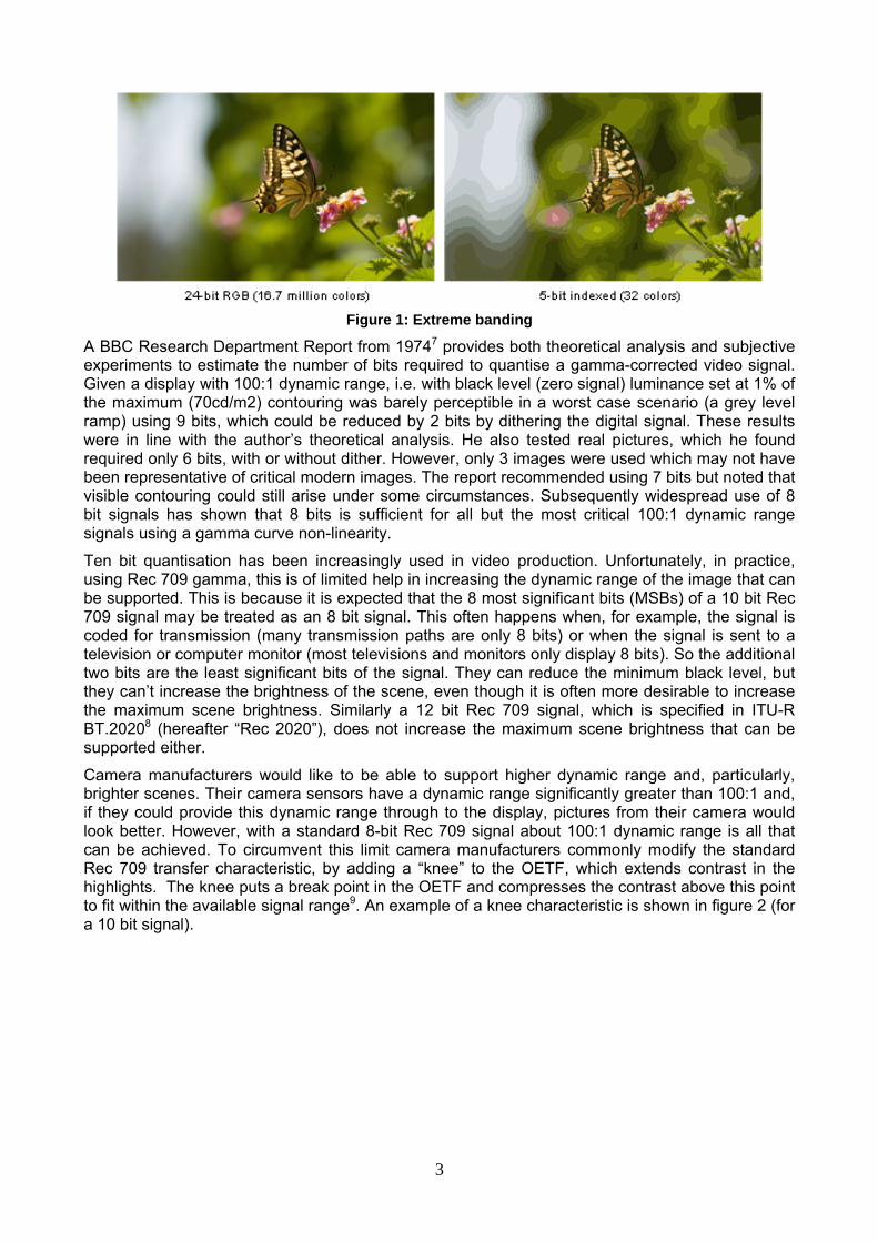
With the advent of digital video it was necessary to find how many bits were required to represent the gamma-corrected signal without introducing additional artefacts. The artefact introduced by using insufficient bits is spurious boundaries introduced in smooth regions of the picture. This artefact is known as “banding”, “contouring” or “posterisation”. Figure 1 provides an extreme example of the effect of contouring.
______________________________________________________________________________ c Although CIE 1976 L* is specified with reference to an exponent of 0.33, the function includes a linear portion around black with changes the overall exponent to 0.42. For more details see reference27. d The “advertised” exponent in Rec 709 is 0.45. However taking the linear portion of the curve near black into account the overall exponent is better approximated by 0.5 (reference28).
3
Figure 1: Extreme banding
A BBC Research Department Report from 19747 provides both theoretical analysis and subjective experiments to estimate the number of bits required to quantise a gamma-corrected video signal. Given a display with 100:1 dynamic range, i.e. with black level (zero signal) luminance set at 1% of the maximum (70cd/m2) contouring was barely perceptible in a worst case scenario (a grey level ramp) using 9 bits, which could be reduced by 2 bits by dithering the digital signal. These results were in line with the author’s theoretical analysis. He also tested real pictures, which he found required only 6 bits, with or without dither. However, only 3 images were used which may not have been representative of critical modern images. The report recommended using 7 bits but noted that visible contouring could still arise under some circumstances. Subsequently widespread use of 8 bit signals has shown that 8 bits is sufficient for all but the most critical 100:1 dynamic range signals using a gamma curve non-linearity.
Ten bit quantisation has been increasingly used in video production. Unfortunately, in practice, using Rec 709 gamma, this is of limited help in increasing the dynamic range of the image that can be supported. This is because it is expected that the 8 most significant bits (MSBs) of a 10 bit Rec 709 signal may be treated as an 8 bit signal. This often happens when, for example, the signal is coded for transmission (many transmission paths are only 8 bits) or when the signal is sent to a television or computer monitor (most televisions and monitors only display 8 bits). So the additional two bits are the least significant bits of the signal. They can reduce the minimum black level, but they can’t increase the brightness of the scene, even though it is often more desirable to increase the maximum scene brightness. Similarly a 12 bit Rec 709 signal, which is specified in ITU-R BT.20208 (hereafter “Rec 2020”), does not increase the maximum scene brightness that can be supported either.
Camera manufacturers would like to be able to support higher dynamic range and, particularly, brighter scenes. Their camera sensors have a dynamic range significantly greater than 100:1 and, if they could provide this dynamic range through to the display, pictures from their camera would look better. However, with a standard 8-bit Rec 709 signal about 100:1 dynamic range is all that can be achieved. To circumvent this limit camera manufacturers commonly modify the standard Rec 709 transfer characteristic, by adding a “knee” to the OETF, which extends contrast in the highlights. The knee puts a break point in the OETF and compresses the contrast above this point to fit within the available signal range9. An example of a knee characteristic is shown in figure 2 (for a 10 bit signal).

4
Figure 2: Example of Knee Transfer Characteristic
In this example the knee is at 100% reference white and the headroom available in the signal (levels 941 to 1019 in SMPTE standards 259 & 292) is used to increase the available exposure to 300% of reference white. Often (e.g. Sony HD camera reference 9, Table 7.2.7) the break point is set at about 85% of reference white output level (corresponding to an input exposure of about 70% of peak white). With an 85% break point the exposure may be extended up to 500% or 600% of reference white. Indeed Roberts9 suggests that, by using a knee, exposure may even be extended to 800% of reference white.
There is a price to pay for using a knee in the Rec 709 OETF. To achieve improvements in exposure, and maintain image quality, the camera must be carefully configured, and the output quality may easily be wrecked by inappropriate adjustments. Even when the camera is well adjusted there is a risk of visible contouring if the knee characteristic is inverted in the display to achieve high dynamic range (discussed in more detail below). The characteristics of the knee depend on the camera and are not standardised. This makes it difficult to take full advantage of the enhanced dynamic range because it is difficult to undo the knee characteristic to return to a linear light format for processing. Consequently, whilst a Rec 709 OETF with knee would typically be used for live TV programmes (for which “grading”e is not possible), alternative approaches may be used for non-live content such as dramas.
The dynamic range of the video signal may be increased by using an alternative OETF. Bear in mind that the gamma curve specified in Rec 709 was designed to produce an approximately uniform perception of video noise in an analogue signal. It was therefore designed to approximate the subjective lightness curve experienced by the human visual system. But in quantising a video signal the objective is to avoid contouring, not to provide uniform perception of noisef. So, in quantising a video signal, the important characteristic is the human visual system’s ability to distinguish similar values of brightness.
The lightness of a visual signal is its subjective (relative) intensity (brightness is the measured intensity). Visual reproduction has historically always tried to reproduce lightness. This is natural because the reproduced brightness of an image is often, necessarily, very different to its original
______________________________________________________________________________ e Grading, also known as colour grading, is the process of optimising the subjective appearance of the programme or film in terms of colour and detail, with particular attention to highlights and low light. f It might be considered that the “banding” artefact due to quantisation is a form of noise. However the characteristics of analogue signal noise and banding are very different, with the former being wideband noise and the latter concentrated at low frequencies. Consequently banding is usually considered to be distinct from analogue noise.

5
brightness. It seems that visual lightness is an example of Steven’s law10, which is that the perceived relative intensity is proportional to a power of the physical relative intensity. As noted previously the best estimate of the exponent for lightness is CIE 1976’s value of 0.42. Consequently an 18% reflectance grey card, often used in the film industry, has a lightness of 50% (0.180.42≈0.5) because it appears midway between black and white.
In quantising a video signal we wish to avoid contouring, and so it is the likelihood of detecting the difference between adjacent quantisation levels that is important (not lightness). The just noticeable difference in brightness is governed by Weber’s law (modified to the De Vries-Rose law at low luminance as discussed below)10. Weber’s law states that the detectable difference between brightness levels is proportional to the brightness. That is, the just noticeable difference in brightness is a constant fraction of the brightness, known as the Weber fraction. The Weber fraction of cone cells in the eye is between 2% and 3%11, which means that subjects can reliably detect a change of between 2% and 3% in brightnessg.
Weber’s law suggests that a logarithmic OETF (signal ∝ log(relative luminance)) would provide the maximum dynamic range whilst rendering quantisation steps equally imperceptible. A Weber fraction of 2% means we could quantise a 100:1 dynamic range, without perceptible contouring, using 233 quantisation levels, i.e. 8 bits. The aforementioned BBC report7 suggests only 9 bits are needed worst case, for a OETF similar to Rec 709, and fewer bits in practice. Hence, for a required dynamic range of 100:1, there is little to be gained from using a logarithmic OETF, which would be incompatible with pre-existing TV equipment.
For movie production the formulation of the film stock ensures a more or less logarithmic response to light12. For decades this has been digitally scanned using a linear analogue to digital converter (ADC). The resulting “Cineon” format13 is essentially a 10 bit signal with a logarithmic OETF. Film provides about 14 stopsh (i.e. 214) of dynamic range, which is satisfactorily captured in the 10 bit Cineon format.
Given the need to produce a video signal with higher dynamic range, and the limitations of the Rec 709 OETF (even with a knee), many electronic camera manufacturers have designed their own OETF (mostly 10 bit). These include: Filestream14 (Thomson), S-Log15 (Sony), Panalog16,17 (Panavision), Log C18 (Arri), Canon Log19 (Canon, only 8 bit). Not surprisingly these are all quasi log curves. Other logarithmic OETFs have been proposed in different contexts20,21,22,i. With a Weber fraction of less than 1%, a 10 bit log transfer characteristic can achieve a dynamic range of greater than 10000:1.
Given the benefits in terms of dynamic range one might ask why a logarithmic transfer characteristic has not been adopted for video production and distribution. The reason seems to be that, hitherto, the dynamic range of TV has been limited to 100:1, which does not require a logarithmic curve, and that a logarithmic curve would be incompatible with the installed television infrastructure. For video production, either a knee characteristic was introduced to extend the dynamic range of video cameras, or non-standard OETFs have been used for capture and then converted to a Rec 709 gamma characteristic after post-production. However, if a higher dynamic range for the end viewer is required in new Ultra High Definition (UHD) television standards a conventional gamma curve, even extended to 12 bits, is no longer adequate.
Miller et al have proposed a new OETF to provide higher dynamic range for video and movie production and distribution23. This is currently being standardised by the Society of Motion Picture Engineers as SMPTE ST 2084. This OETF is based on the human contrast sensitivity model developed by Barten24. Their “ideal” OETF is modelled in the equations below. Here V is the signal value and Y is the brightness. ______________________________________________________________________________ g Weber’s law of just noticeable difference is well tested experimentally. When just noticeable differences are integrated it gives Fechner's scale, which hypothesises a logarithmic relationship between brightness and the sensation of lightness. However lightness is known to be a power law of brightness, reference5. Hence Fechner's scale does not apply to lightness. For more discussion see reference27, paragraph bottom left of page 9, and the references therein. h In photography the term “stop” is used to denote a factor of two. i ITU-T H.264/MPEG AVC & ITU-T H.265/MPEG HEVC both define two logarithmic transfer characteristics in Table E4, options 8 & 9.
6
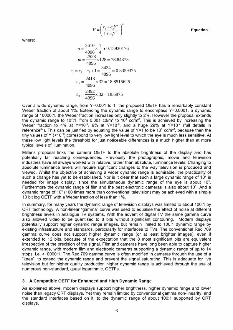
m
n
n
YcYccV ⎟⎟
⎠
⎞⎜⎜⎝
⎛++
=3
21
1 Equation 1
where:
6875.183240962392
8515625.183240962413
8359375.0409634241
84375.7812840962523
15930176.041
40962610
3
2
231
=×=
=×=
==+−=
=×=
≈×=
c
c
ccc
m
n
Over a wide dynamic range, from Y=0.001 to 1, the proposed OETF has a remarkably constant Weber fraction of about 1%. Extending the dynamic range to encompass Y=0.0001, a dynamic range of 10000:1, the Weber fraction increases only slightly to 2%. However the proposal extends the dynamic range to 107:1, from 0.001 cd/m2 to 104 cd/m2. This is achieved by increasing the Weber fraction to 4% at Y=10-5, 9% at Y=10-6, and a huge 29% at Y=10-7 (full details in reference23). This can be justified by equating the value of Y=1 to be 104 cd/m2, because then the tiny values of Y (<10-4) correspond to very low light level to which the eye is much less sensitive. At these low light levels the threshold for just noticeable differences is a much higher than at more typical levels of illumination.
Miller’s proposal links the camera OETF to the absolute brightness of the display and has potentially far reaching consequences. Previously the photographic, movie and television industries have all always worked with relative, rather than absolute, luminance levels. Changing to absolute luminance levels will require significant changes to the way television is produced and viewed. Whilst the objective of achieving a wider dynamic range is admirable, the practicality of such a change has yet to be established. Nor is it clear that such a large dynamic range of 107 is needed for image display, since the simultaneous dynamic range of the eye is about 104. Furthermore the dynamic range of film and the best electronic cameras is also about 104. And a dynamic range of 104 (100 times more than conventional television) may be achieved with a simple 10 bit log OETF with a Weber fraction of less than 1%.
In summary, for many years the dynamic range of television displays was limited to about 100:1 by CRT technology. A non-linear “gamma” curve was used to equalise the effect of noise at different brightness levels in analogue TV systems. With the advent of digital TV the same gamma curve also allowed video to be quantised to 8 bits without significant contouring. Modern displays potentially support higher dynamic range images, but remain limited to 100:1 dynamic range by existing infrastructure and standards, particularly for interfaces to TVs. The conventional Rec 709 gamma curve does not support higher dynamic range (or at least brighter images), even if extended to 12 bits, because of the expectation that the 8 most significant bits are equivalent irrespective of the precision of the signal. Film and cameras have long been able to capture higher dynamic range, with modern film and electronic cameras supporting a dynamic range of up to 14 stops, i.e. >10000:1. The Rec 709 gamma curve is often modified in cameras through the use of a “knee”, to extend the dynamic range and prevent the signal saturating. This is adequate for live television but for higher quality production higher dynamic range is achieved through the use of numerous non-standard, quasi logarithmic, OETFs.
3 A Compatible OETF for Enhanced and High Dynamic Range As explained above, modern displays support higher brightness, higher dynamic range and lower noise than legacy CRT displays. Yet they remain limited by conventional gamma non-linearity, and the standard interfaces based on it, to the dynamic range of about 100:1 supported by CRT displays.
7
In order to exploit the potential of modern displays a signal format, based on a new OETF, is needed. This paper proposes a new OETF for high dynamic range video which is broadly compatible with Rec 709. Clearly no new OETF can be completely compatible with Rec 709 (else it would actually be Rec 709). However the new OETF has similar characteristics to Rec 709, and so facilitates compression and video processing using systems designed for Rec 709, and allows the display of pictures on existing displays with a quality at least sufficient for monitoring purposes.
A new OETF would allow video to provide greater impact and a more immersive experience. It should support a dynamic range of at least 1000:1 and preferably significantly more. Even a dynamic range of 1000:1, using a logarithmic OETF, would require a Weber fraction of about 3% if the signal is quantised to 8 bits. A 3% Weber fraction is barely, if at all, adequate to avoid visible contouring in the displayed image, which suggests a new OETF will need more than 8 bits of precision.
Any new OETF should interoperate with existing standards and infrastructure. Ideally a new signal format should be able to be carried over existing video connections (including compression) and be displayed, in a broadly compatible fashion, on existing 8 and 10 bit displays. Television will increasingly encompass multiple formats (e.g. SD, HD and UHD) and frame rates. So a new signal format should also, ideally, be compatible with processing such as spatial up and down conversion and frame rate (“standards”) conversion.
Not all OETFs would be equally compatible with existing standards and infrastructure. Any reasonable 10 bit OETF may be carried over existing 10 bit interconnects. However the more the signal differs from the conventional Rec 709 characteristic the less compatible it will be with existing video compression, processing and, particularly, displays. Video compression is optimised for the characteristics of conventional video, so that new formats are likely to require greater bit rate and/or exhibit more artefacts. Video processing is typically performed on non-linear signals so a new signal format may degrade the quality of such processing. Clearly a signal that is radically different from Rec 709 will be significantly distorted on a conventional display. Potential display distortion includes altered brightness, changed colours, reduced or excessive sharpness and contouring. For this reason both (quasi) logarithmic OETFs and the perceptual OETF proposed by Miller et al23 are likely to present considerable practical difficulties if used with conventional infra-structure. Clearly there are advantages to a new format that is broadly similar to Rec 709.
The construction of the proposed OETF is inspired by Rec 709 and the use of “knee” characteristics in cameras. Rec 709 is already a two part curve with a linear part near black and a power law (gamma curve) for the majority of the input range. It is designed so that the value and the gradient of both curves match at the transition between them. Camera makers often modify the OETF by adding a third section near white, by using a “knee”, to increase dynamic range and avoid clipping the signal. Unfortunately the section added above the “knee” risks introducing contouring artefacts (when inverted by an EOTF) by failing to take full account of the psychovisual aspects of vision.
This proposal is to add a third part to the Rec 709 curve, at higher input luminance, to extend the dynamic range without re-introducing the risk of contouring. The new, upper portion, of the curve is a logarithmic function to allow for the non-linear response of the eye. And, as with the linear portion of the Rec 709 curve, the output value and the gradient of both curves are designed to match at the transition between them. Because this new proposal has some similarities to the widely used knee characteristic in cameras we can be confident that it is broadly compatible with Rec 709.
The OETF defined in Rec 709 is:
⎩⎨⎧
≤≤−<≤
=1018.0for 099.0099.1
018.00for 5.445.0 LL
LLV Equation 2
where L is luminance of the image 0≤L≤1 and where V is the corresponding electrical signal. In Rec 2020 “Parameter values for ultra-high definition television systems for production and international programme exchange”, the same equation is specified as:
8
⎩⎨⎧
≤≤β−α−α
β<≤=′
1),1(0,5.4
45.0 EEEE
E Equation 3
“where E is voltage normalized by the reference white level and proportional to the implicit light intensity that would be detected with a reference camera colour channel R, G, B; E' is the resulting non-linear signal. α = 1.099 and β = 0.018 for 10-bit system α = 1.0993 and β = 0.0181 for 12-bit system” Although not explicitly stated α and β are the solution to the following simultaneous equations:
( )55.0
45.0
45.05.415.4
−=−−=
αβααββ
Equation 4
The first equates the values of a linear function and the gamma function at E= β, and the second equates the gradient of the two functions also at E= β, thereby ensuring a smooth transition between the two parts of the curve.
This proposal adds a third, logarithmic, portion to the transfer function at higher values of luminance such that:
( )( )⎪
⎩
⎪⎨
⎧
>+≤≤−−<≤
=μρημβααβ
Lfor lnfor 1
0for 5.445.0
LLLLL
V Equation 5
This proposal was made to the ITUj, Study Group 6 (SG 6, Broadcasting Service), Working Party 6C (WP 6C, Programme production and quality assessment) at their meeting in Geneva in March 2014.
The proposal in equation 5 uses the V and L notation from Rec 709 to avoid the confusion of having both dashed and un-dashed versions of the same variable (as in Rec 2020). Here L is still normalised to the same reference white level as Rec 709, but now L can exceed unity, i.e. this transfer function supports luminance greater than reference white. α and β are as defined in Rec 2020. μ, the breakpoint between the gamma and logarithmic sections of the curve, determines the maximum value of L for which V≤1, which is discussed in more detail below. The values of η and ρ are determined by equating the derivatives and the values of the gamma and log curves at the breakpoint μ. Equating the derivatives yields:
45.045.0 αμη = Equation 6
And equating the values of the curves at μ (and substituting for η) yields: ( ) ( )1ln45.0145.0 −−−= αμαμρ Equation 7
The breakpoint between the gamma and log parts of the curves must be selected. It determines by how much the input luminance level may exceed reference white. It also determines how compatible the proposed transfer function is with the conventional Rec 709 curve. A low value of μ gives a higher dynamic range but a poorer compatibility with Rec 709. So the choice of μ is a compromise. With a little algebra the value of luminance at the maximum output V=1, may be found to be:
⎟⎟⎠
⎞⎜⎜⎝
⎛⎟⎟⎠
⎞⎜⎜⎝
⎛−= 11
45.01exp 45.0max μ
μL Equation 8
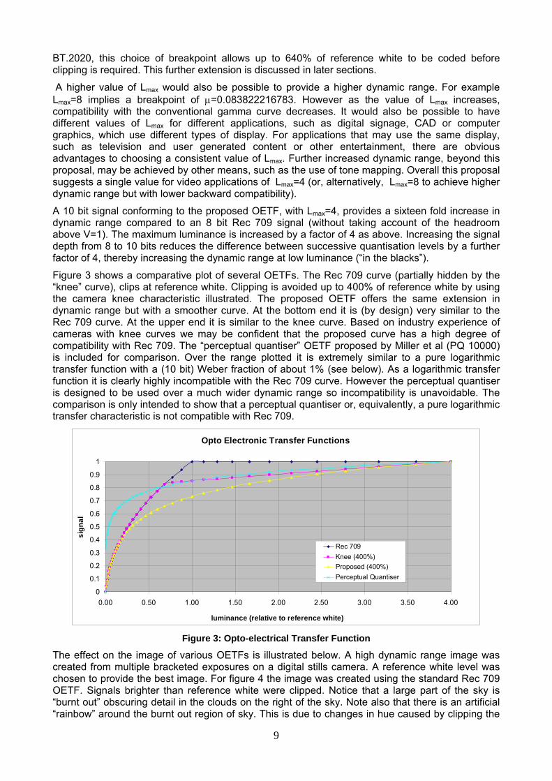
This paper suggests that the maximum value of luminance (when V=1), relative to reference white, should be Lmax=4. This supports good backward compatibility and, for a 10 bit signal, at least a sixteen fold increase in dynamic range compared to 8 bit Rec 709. Lmax=4 implies a breakpoint of μ=0.12314858. The corresponding output level is V=0.33 but, in practice, Rec 709 and this proposal are very similar for the whole of lower half of the output range. Taking into account headroom above V=1, which is allowed in the 10 bit coding scheme defined in Rec 709 and ______________________________________________________________________________ j The ITU (International Telecommunication Union) is the United Nations specialized agency for information and communication technologies – ICTs.
9
BT.2020, this choice of breakpoint allows up to 640% of reference white to be coded before clipping is required. This further extension is discussed in later sections.
A higher value of Lmax would also be possible to provide a higher dynamic range. For example Lmax=8 implies a breakpoint of μ=0.083822216783. However as the value of Lmax increases, compatibility with the conventional gamma curve decreases. It would also be possible to have different values of Lmax for different applications, such as digital signage, CAD or computer graphics, which use different types of display. For applications that may use the same display, such as television and user generated content or other entertainment, there are obvious advantages to choosing a consistent value of Lmax. Further increased dynamic range, beyond this proposal, may be achieved by other means, such as the use of tone mapping. Overall this proposal suggests a single value for video applications of Lmax=4 (or, alternatively, Lmax=8 to achieve higher dynamic range but with lower backward compatibility).
A 10 bit signal conforming to the proposed OETF, with Lmax=4, provides a sixteen fold increase in dynamic range compared to an 8 bit Rec 709 signal (without taking account of the headroom above V=1). The maximum luminance is increased by a factor of 4 as above. Increasing the signal depth from 8 to 10 bits reduces the difference between successive quantisation levels by a further factor of 4, thereby increasing the dynamic range at low luminance (“in the blacks”).
Figure 3 shows a comparative plot of several OETFs. The Rec 709 curve (partially hidden by the “knee” curve), clips at reference white. Clipping is avoided up to 400% of reference white by using the camera knee characteristic illustrated. The proposed OETF offers the same extension in dynamic range but with a smoother curve. At the bottom end it is (by design) very similar to the Rec 709 curve. At the upper end it is similar to the knee curve. Based on industry experience of cameras with knee curves we may be confident that the proposed curve has a high degree of compatibility with Rec 709. The “perceptual quantiser” OETF proposed by Miller et al (PQ 10000) is included for comparison. Over the range plotted it is extremely similar to a pure logarithmic transfer function with a (10 bit) Weber fraction of about 1% (see below). As a logarithmic transfer function it is clearly highly incompatible with the Rec 709 curve. However the perceptual quantiser is designed to be used over a much wider dynamic range so incompatibility is unavoidable. The comparison is only intended to show that a perceptual quantiser or, equivalently, a pure logarithmic transfer characteristic is not compatible with Rec 709.
Opto Electronic Transfer Functions
0
0.1
0.2
0.3
0.4
0.5
0.6
0.7
0.8
0.9
1
0.00 0.50 1.00 1.50 2.00 2.50 3.00 3.50 4.00
luminance (relative to reference white)
sign
al
Rec 709Knee (400%)Proposed (400%)Perceptual Quantiser
Figure 3: Opto-electrical Transfer Function
The effect on the image of various OETFs is illustrated below. A high dynamic range image was created from multiple bracketed exposures on a digital stills camera. A reference white level was chosen to provide the best image. For figure 4 the image was created using the standard Rec 709 OETF. Signals brighter than reference white were clipped. Notice that a large part of the sky is “burnt out” obscuring detail in the clouds on the right of the sky. Note also that there is an artificial “rainbow” around the burnt out region of sky. This is due to changes in hue caused by clipping the

10
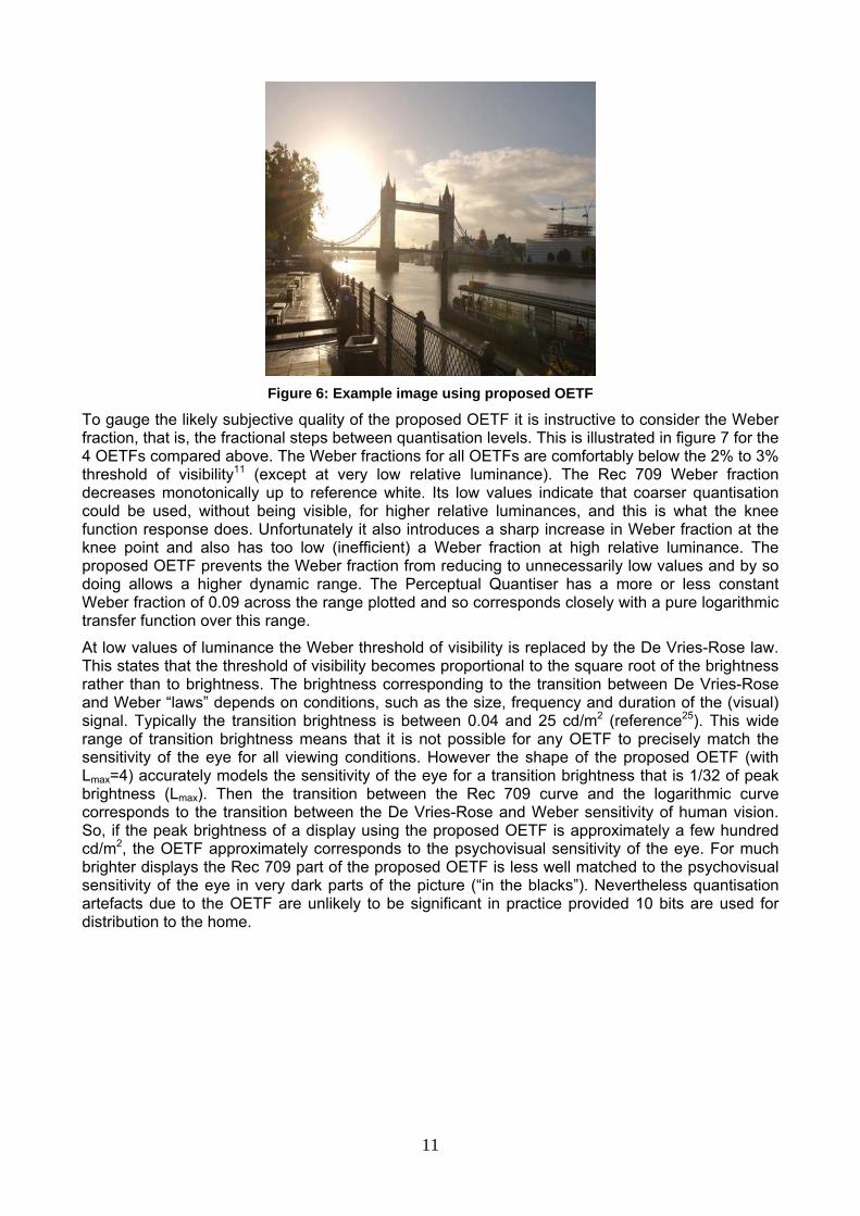
R, G and B component of the image separately. Furthermore in this image detail in the water and on the path is obscured by reflections of the sun. The image in figure 5 was produced using Rec 709 OETF with a knee as illustrated in figure 3. Signals brighter than four times reference white were clipped. The artefacts in this image are reduced, compared to using the standard Rec 709 OETF, particularly in the sky. Figure 6 was produced using the proposed OETF, with the signal clipped beyond four times reference white. Whilst some artefacts remain they are much reduced in the sky, on the water, and on the path. The image in figure 6 is not, of course, high dynamic range image because it is reproduced here on a standard dynamic range media. However figure 6 does serve to illustrate the reduction in artefacts due to a standard Rec 709 OETF that can be achieved using a modified transfer function.
Figure 4: Example image using Rec 709 OETF
Figure 5: Example image using BT.709 OETF with "knee"
11
Figure 6: Example image using proposed OETF
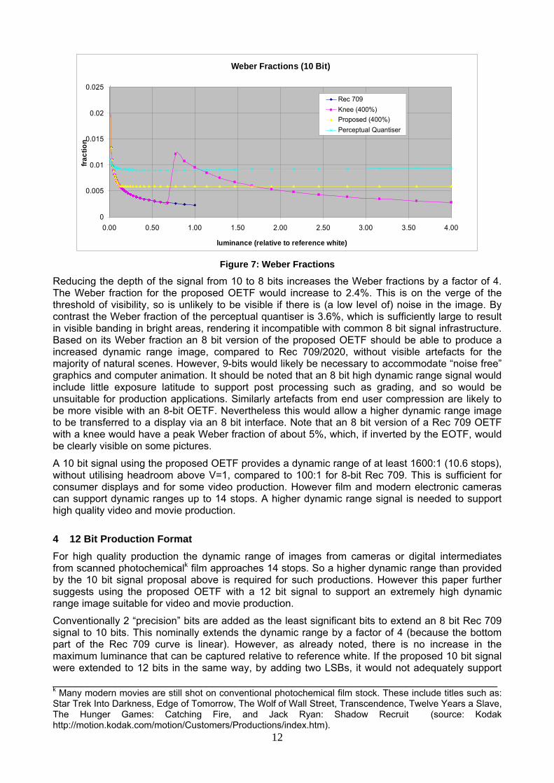
To gauge the likely subjective quality of the proposed OETF it is instructive to consider the Weber fraction, that is, the fractional steps between quantisation levels. This is illustrated in figure 7 for the 4 OETFs compared above. The Weber fractions for all OETFs are comfortably below the 2% to 3% threshold of visibility11 (except at very low relative luminance). The Rec 709 Weber fraction decreases monotonically up to reference white. Its low values indicate that coarser quantisation could be used, without being visible, for higher relative luminances, and this is what the knee function response does. Unfortunately it also introduces a sharp increase in Weber fraction at the knee point and also has too low (inefficient) a Weber fraction at high relative luminance. The proposed OETF prevents the Weber fraction from reducing to unnecessarily low values and by so doing allows a higher dynamic range. The Perceptual Quantiser has a more or less constant Weber fraction of 0.09 across the range plotted and so corresponds closely with a pure logarithmic transfer function over this range.
At low values of luminance the Weber threshold of visibility is replaced by the De Vries-Rose law. This states that the threshold of visibility becomes proportional to the square root of the brightness rather than to brightness. The brightness corresponding to the transition between De Vries-Rose and Weber “laws” depends on conditions, such as the size, frequency and duration of the (visual) signal. Typically the transition brightness is between 0.04 and 25 cd/m2 (reference25). This wide range of transition brightness means that it is not possible for any OETF to precisely match the sensitivity of the eye for all viewing conditions. However the shape of the proposed OETF (with Lmax=4) accurately models the sensitivity of the eye for a transition brightness that is 1/32 of peak brightness (Lmax). Then the transition between the Rec 709 curve and the logarithmic curve corresponds to the transition between the De Vries-Rose and Weber sensitivity of human vision. So, if the peak brightness of a display using the proposed OETF is approximately a few hundred cd/m2, the OETF approximately corresponds to the psychovisual sensitivity of the eye. For much brighter displays the Rec 709 part of the proposed OETF is less well matched to the psychovisual sensitivity of the eye in very dark parts of the picture (“in the blacks”). Nevertheless quantisation artefacts due to the OETF are unlikely to be significant in practice provided 10 bits are used for distribution to the home.
12
Figure 7: Weber Fractions
Reducing the depth of the signal from 10 to 8 bits increases the Weber fractions by a factor of 4. The Weber fraction for the proposed OETF would increase to 2.4%. This is on the verge of the threshold of visibility, so is unlikely to be visible if there is (a low level of) noise in the image. By contrast the Weber fraction of the perceptual quantiser is 3.6%, which is sufficiently large to result in visible banding in bright areas, rendering it incompatible with common 8 bit signal infrastructure. Based on its Weber fraction an 8 bit version of the proposed OETF should be able to produce a increased dynamic range image, compared to Rec 709/2020, without visible artefacts for the majority of natural scenes. However, 9-bits would likely be necessary to accommodate “noise free” graphics and computer animation. It should be noted that an 8 bit high dynamic range signal would include little exposure latitude to support post processing such as grading, and so would be unsuitable for production applications. Similarly artefacts from end user compression are likely to be more visible with an 8-bit OETF. Nevertheless this would allow a higher dynamic range image to be transferred to a display via an 8 bit interface. Note that an 8 bit version of a Rec 709 OETF with a knee would have a peak Weber fraction of about 5%, which, if inverted by the EOTF, would be clearly visible on some pictures.
A 10 bit signal using the proposed OETF provides a dynamic range of at least 1600:1 (10.6 stops), without utilising headroom above V=1, compared to 100:1 for 8-bit Rec 709. This is sufficient for consumer displays and for some video production. However film and modern electronic cameras can support dynamic ranges up to 14 stops. A higher dynamic range signal is needed to support high quality video and movie production.
4 12 Bit Production Format For high quality production the dynamic range of images from cameras or digital intermediates from scanned photochemicalk film approaches 14 stops. So a higher dynamic range than provided by the 10 bit signal proposal above is required for such productions. However this paper further suggests using the proposed OETF with a 12 bit signal to support an extremely high dynamic range image suitable for video and movie production.
Conventionally 2 “precision” bits are added as the least significant bits to extend an 8 bit Rec 709 signal to 10 bits. This nominally extends the dynamic range by a factor of 4 (because the bottom part of the Rec 709 curve is linear). However, as already noted, there is no increase in the maximum luminance that can be captured relative to reference white. If the proposed 10 bit signal were extended to 12 bits in the same way, by adding two LSBs, it would not adequately support ______________________________________________________________________________ k Many modern movies are still shot on conventional photochemical film stock. These include titles such as: Star Trek Into Darkness, Edge of Tomorrow, The Wolf of Wall Street, Transcendence, Twelve Years a Slave, The Hunger Games: Catching Fire, and Jack Ryan: Shadow Recruit (source: Kodak http://motion.kodak.com/motion/Customers/Productions/index.htm).
Weber Fractions (10 Bit)
0
0.005
0.01
0.015
0.02
0.025
0.00 0.50 1.00 1.50 2.00 2.50 3.00 3.50 4.00
luminance (relative to reference white)
fract
ion
Rec 709Knee (400%)Proposed (400%)Perceptual Quantiser

13
the needs of video and movie production. Such a 12 bit signal would support a dynamic range of at most about 12 stops and a maximum luminance of 4 times reference white.
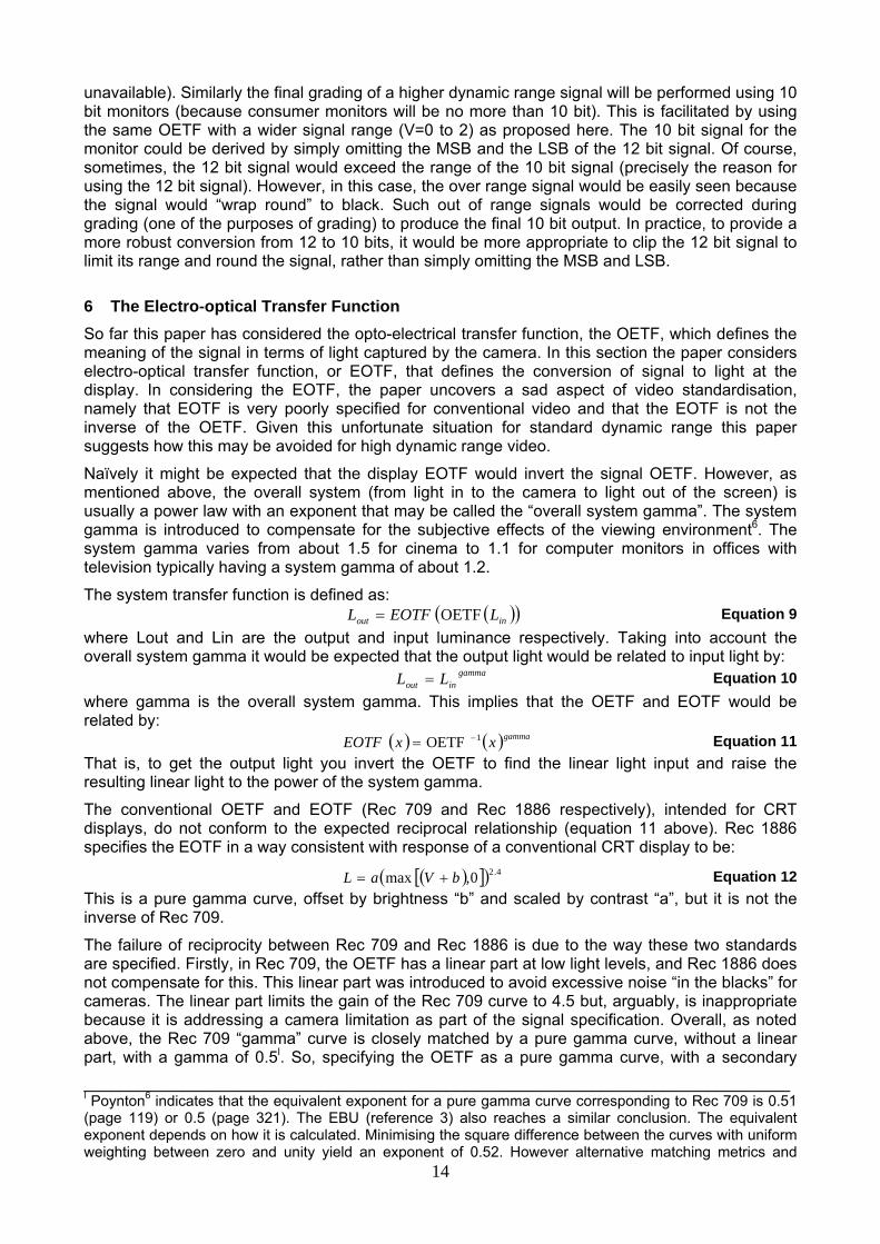
It is proposed to extend the 10 bit signal to 12 bits by adding one MSB plus one LSB. This means doubling the range of the signal (V or E’ in the equations above), from 0 to 2, and increasing its precision by a factor of two. A signal value V=2.0, with the OETF proposed above, corresponds to a luminance of 716 times reference white, (or 1836 times reference white if the headroom above V=2.0 is exploited). The additional bit of precision also extends the dynamic range by a factor of two, i.e. 1 stop, “in the blacks”. Overall a 12 bit signal, constructed in this way would have a dynamic range of more than 20 stops. This is many stops more than the best film or electronic cameras providing plenty of scope for future improvements and, potentially, plenty of exposure latitude to meet the most demanding production requirements.
Figure 8: Proposed 12 Bit Production Format
Figure 8 shows the proposed 12 bit production format compared to the 10 bit format for distribution. Note that the dynamic range figures here correspond to the ITU definition of signal dynamic range, discussed in the introduction, and are shown here for comparison with other proposals for HDR OETFs. For comparison the signal dynamic range of 8 bit Rec 709, using the same definition, is about 10 stops, or 1000:1. However low signal levels are subject to “banding” which is why this definition of dynamic range is not used elsewhere in this paper.
5 Compatibility with 8 and 10 Bits For video production in standard definition (ITU-R BT.601) or high definition (Rec 709) both 8 and 10 bit signals are valid formats. 10 bit signals have been increasingly used for video production (although 8 bit signals are still sometimes used) but only 8 bits are currently ever used for end user distribution. To allow interoperation of 8 and 10 bit equipment simple conversion between the 8 and 10 bit signals is essential. If 8 bit signals continue to be used for HDR (which is possible as discussed above) this will continue to be true. Simple conversion is afforded through the addition of precision bits to the 8 bit signal as the LSBs (as discussed above) to give a 10 bit signal. Conversion from 10 to 8 bits may be performed by truncation or rounding. This remains true for the proposal herein.
There is no requirement, in extending a higher dynamic range video format to 12 bits, to use only precision bits. There is virtually no 12 bit video equipment in existing broadcast infrastructure, so there is no requirement for backward compatibility. Indeed, as already noted, the use of only precision bits would not support the needs of high quality production.
Using the 12 bit format proposed here would support easy interoperation with 10 (and 8) bit equipment. There are currently no proposals to use 12 bits for end user distribution, so the 12 bit format would only be used for production to provide exposure latitude during grading and post production. Today’s proprietary higher dynamic range formats (such as Log C or Panalog discussed above) are graded on monitors with 10 input bits (higher bit depth monitors are virtually
14
unavailable). Similarly the final grading of a higher dynamic range signal will be performed using 10 bit monitors (because consumer monitors will be no more than 10 bit). This is facilitated by using the same OETF with a wider signal range (V=0 to 2) as proposed here. The 10 bit signal for the monitor could be derived by simply omitting the MSB and the LSB of the 12 bit signal. Of course, sometimes, the 12 bit signal would exceed the range of the 10 bit signal (precisely the reason for using the 12 bit signal). However, in this case, the over range signal would be easily seen because the signal would “wrap round” to black. Such out of range signals would be corrected during grading (one of the purposes of grading) to produce the final 10 bit output. In practice, to provide a more robust conversion from 12 to 10 bits, it would be more appropriate to clip the 12 bit signal to limit its range and round the signal, rather than simply omitting the MSB and LSB.
6 The Electro-optical Transfer Function So far this paper has considered the opto-electrical transfer function, the OETF, which defines the meaning of the signal in terms of light captured by the camera. In this section the paper considers electro-optical transfer function, or EOTF, that defines the conversion of signal to light at the display. In considering the EOTF, the paper uncovers a sad aspect of video standardisation, namely that EOTF is very poorly specified for conventional video and that the EOTF is not the inverse of the OETF. Given this unfortunate situation for standard dynamic range this paper suggests how this may be avoided for high dynamic range video.
Naïvely it might be expected that the display EOTF would invert the signal OETF. However, as mentioned above, the overall system (from light in to the camera to light out of the screen) is usually a power law with an exponent that may be called the “overall system gamma”. The system gamma is introduced to compensate for the subjective effects of the viewing environment6. The system gamma varies from about 1.5 for cinema to 1.1 for computer monitors in offices with television typically having a system gamma of about 1.2.
The system transfer function is defined as: ( )( )inout LEOTFL OETF= Equation 9
where Lout and Lin are the output and input luminance respectively. Taking into account the overall system gamma it would be expected that the output light would be related to input light by:
gammainout LL = Equation 10
where gamma is the overall system gamma. This implies that the OETF and EOTF would be related by:
( ) ( )gammaxxEOTF 1OETF −= Equation 11 That is, to get the output light you invert the OETF to find the linear light input and raise the resulting linear light to the power of the system gamma.
The conventional OETF and EOTF (Rec 709 and Rec 1886 respectively), intended for CRT displays, do not conform to the expected reciprocal relationship (equation 11 above). Rec 1886 specifies the EOTF in a way consistent with response of a conventional CRT display to be:
( )[ ]( ) 4.20,max bVaL += Equation 12 This is a pure gamma curve, offset by brightness “b” and scaled by contrast “a”, but it is not the inverse of Rec 709.
The failure of reciprocity between Rec 709 and Rec 1886 is due to the way these two standards are specified. Firstly, in Rec 709, the OETF has a linear part at low light levels, and Rec 1886 does not compensate for this. This linear part was introduced to avoid excessive noise “in the blacks” for cameras. The linear part limits the gain of the Rec 709 curve to 4.5 but, arguably, is inappropriate because it is addressing a camera limitation as part of the signal specification. Overall, as noted above, the Rec 709 “gamma” curve is closely matched by a pure gamma curve, without a linear part, with a gamma of 0.5l. So, specifying the OETF as a pure gamma curve, with a secondary ______________________________________________________________________________ l Poynton6 indicates that the equivalent exponent for a pure gamma curve corresponding to Rec 709 is 0.51 (page 119) or 0.5 (page 321). The EBU (reference 3) also reaches a similar conclusion. The equivalent exponent depends on how it is calculated. Minimising the square difference between the curves with uniform weighting between zero and unity yield an exponent of 0.52. However alternative matching metrics and
15
recommendation about how to manage noise in the black, might have been more appropriate. Secondly, in Rec 1886, the EOTF has an, undefined, black offset (the “brightness” control). The purpose of this is to tone map low light detail (“in the blacks”) so that they can be seen on a lower dynamic range display. Whilst this is a necessary and useful user control it nevertheless results in non-reciprocity between OETF and EOTF.
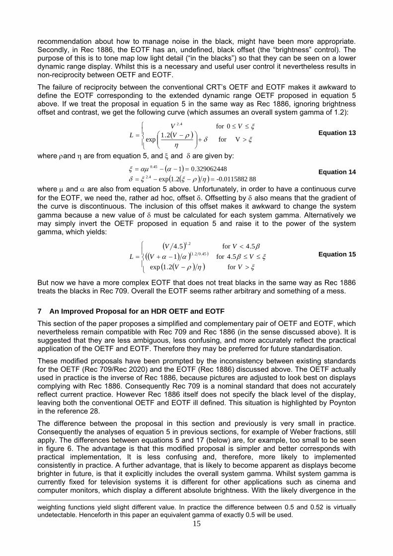
The failure of reciprocity between the conventional CRT’s OETF and EOTF makes it awkward to define the EOTF corresponding to the extended dynamic range OETF proposed in equation 5 above. If we treat the proposal in equation 5 in the same way as Rec 1886, ignoring brightness offset and contrast, we get the following curve (which assumes an overall system gamma of 1.2):
( )⎪⎩
⎪⎨⎧
>+⎟⎟⎠
⎞⎜⎜⎝
⎛ −≤≤
= ξδη
ρξ
Vfor2.1exp
0for 4.2
VVV
L
Equation 13
where ρand η are from equation 5, and ξ and δ are given by:
( )( )( ) 88-0.01158822.1exp
329062448.014.2
45.0
=−−==−−=
ηρξξδααμξ
Equation 14
where μ and α are also from equation 5 above. Unfortunately, in order to have a continuous curve for the EOTF, we need the, rather ad hoc, offset δ. Offsetting by δ also means that the gradient of the curve is discontinuous. The inclusion of this offset makes it awkward to change the system gamma because a new value of δ must be calculated for each system gamma. Alternatively we may simply invert the OETF proposed in equation 5 and raise it to the power of the system gamma, which yields:
( )( )( )( )
( )( )⎪⎩
⎪⎨
⎧
>−≤≤−+
<=
ξηρξβαα
β
VVVV
VVL
for 2.1exp.54for 1
.54for 5.445.02.1
2.1
Equation 15
But now we have a more complex EOTF that does not treat blacks in the same way as Rec 1886 treats the blacks in Rec 709. Overall the EOTF seems rather arbitrary and something of a mess.
7 An Improved Proposal for an HDR OETF and EOTF This section of the paper proposes a simplified and complementary pair of OETF and EOTF, which nevertheless remain compatible with Rec 709 and Rec 1886 (in the sense discussed above). It is suggested that they are less ambiguous, less confusing, and more accurately reflect the practical application of the OETF and EOTF. Therefore they may be preferred for future standardisation.
These modified proposals have been prompted by the inconsistency between existing standards for the OETF (Rec 709/Rec 2020) and the EOTF (Rec 1886) discussed above. The OETF actually used in practice is the inverse of Rec 1886, because pictures are adjusted to look best on displays complying with Rec 1886. Consequently Rec 709 is a nominal standard that does not accurately reflect current practice. However Rec 1886 itself does not specify the black level of the display, leaving both the conventional OETF and EOTF ill defined. This situation is highlighted by Poynton in the reference 28.
The difference between the proposal in this section and previously is very small in practice. Consequently the analyses of equation 5 in previous sections, for example of Weber fractions, still apply. The differences between equations 5 and 17 (below) are, for example, too small to be seen in figure 6. The advantage is that this modified proposal is simpler and better corresponds with practical implementation, It is less confusing and, therefore, more likely to implemented consistently in practice. A further advantage, that is likely to become apparent as displays become brighter in future, is that it explicitly includes the overall system gamma. Whilst system gamma is currently fixed for television systems it is different for other applications such as cinema and computer monitors, which display a different absolute brightness. With the likely divergence in the weighting functions yield slight different value. In practice the difference between 0.5 and 0.52 is virtually undetectable. Henceforth in this paper an equivalent gamma of exactly 0.5 will be used.
16
brightness of television displays the ability to adjust system gamma could be a considerable advantage, which is awkward or impossible to achieve with either Rec 709/Rec 1886 or with the proposal to the ITU above.
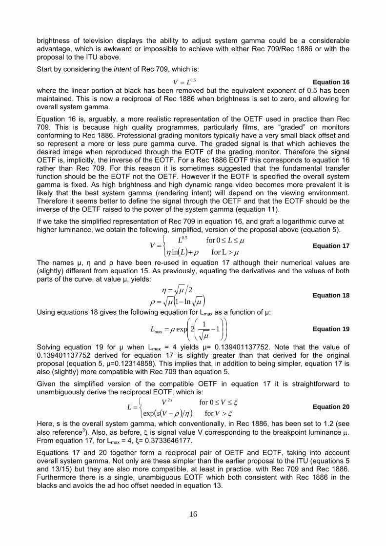
Start by considering the intent of Rec 709, which is: 5.0LV = Equation 16
where the linear portion at black has been removed but the equivalent exponent of 0.5 has been maintained. This is now a reciprocal of Rec 1886 when brightness is set to zero, and allowing for overall system gamma.
Equation 16 is, arguably, a more realistic representation of the OETF used in practice than Rec 709. This is because high quality programmes, particularly films, are “graded” on monitors conforming to Rec 1886. Professional grading monitors typically have a very small black offset and so represent a more or less pure gamma curve. The graded signal is that which achieves the desired image when reproduced through the EOTF of the grading monitor. Therefore the signal OETF is, implicitly, the inverse of the EOTF. For a Rec 1886 EOTF this corresponds to equation 16 rather than Rec 709. For this reason it is sometimes suggested that the fundamental transfer function should be the EOTF not the OETF. However if the EOTF is specified the overall system gamma is fixed. As high brightness and high dynamic range video becomes more prevalent it is likely that the best system gamma (rendering intent) will depend on the viewing environment. Therefore it seems better to define the signal through the OETF and that the EOTF should be the inverse of the OETF raised to the power of the system gamma (equation 11).
If we take the simplified representation of Rec 709 in equation 16, and graft a logarithmic curve at higher luminance, we obtain the following, simplified, version of the proposal above (equation 5).
( )⎩⎨⎧
>+≤≤
=μρημ
Lfor ln0for 5.0
LLL
V Equation 17
The names μ, η and ρ have been re-used in equation 17 although their numerical values are (slightly) different from equation 15. As previously, equating the derivatives and the values of both parts of the curve, at value μ, yields:
( )μμρμη
ln12
−==
Equation 18
Using equations 18 gives the following equation for Lmax as a function of μ:
⎟⎟⎠
⎞⎜⎜⎝
⎛⎟⎟⎠
⎞⎜⎜⎝
⎛−= 112expmax μ
μL
Equation 19
Solving equation 19 for μ when Lmax = 4 yields μ= 0.139401137752. Note that the value of 0.139401137752 derived for equation 17 is slightly greater than that derived for the original proposal (equation 5, μ=0.12314858). This implies that, in addition to being simpler, equation 17 is also (slightly) more compatible with Rec 709 than equation 5.
Given the simplified version of the compatible OETF in equation 17 it is straightforward to unambiguously derive the reciprocal EOTF, which is:
( )( )⎩⎨⎧
>−≤≤
=ξηρξ
VVsVV
Ls
for exp0for 2
Equation 20
Here, s is the overall system gamma, which conventionally, in Rec 1886, has been set to 1.2 (see also reference3). Also, as before, ξ is signal value V corresponding to the breakpoint luminance μ. From equation 17, for Lmax = 4, ξ= 0.3733646177.
Equations 17 and 20 together form a reciprocal pair of OETF and EOTF, taking into account overall system gamma. Not only are these simpler than the earlier proposal to the ITU (equations 5 and 13/15) but they are also more compatible, at least in practice, with Rec 709 and Rec 1886. Furthermore there is a single, unambiguous EOTF which both consistent with Rec 1886 in the blacks and avoids the ad hoc offset needed in equation 13.
17
8 Dynamic Range of the Proposed Transfer Functions The whole purpose of changing the conventional television gamma curves is to provide substantially enhanced dynamic range. At first sight merely increasing the peak brightness by a factor of 4 (Lmax = 4) does not achieve this objective. However this is misleading and the proposed OETF/EOTF does, in fact, provide a very substantial increase in dynamic range.
Several factors combine to increase the dynamic range substantially beyond the “headline” factor of 4 implied by Lmax = 4. Firstly high dynamic range video is likely to be distributed with 10 bit precision, rather than the 8 bit precision that is ubiquitous for contemporary (high and standard definition) television. This means that for a given level of quantisation the black level may be decrease by a factor of 4, or equivalently the peak white may be 4 times brighter. Secondly we may use additional code levels (that is, levels 235 to 254 for an 8 bit signal or levels 941 to 1019 for a 10 bit signal), that are currently unused or only used for signal overshoots. This increases the peak white level (corresponding to V=1.09) to a (relative) value of about 6.5 rather than 4. And thirdly the brightness on the screen is further increased by the system gamma. Therefore, relative to the conventional OETF/EOTF gamma curves, the dynamic range is increased by a factor of 4x6.5 raised to the system gamma. Overall the proposed enhanced gamma curves (e.g. equations 17 & 20) increase the dynamic range, relative to standard dynamic range, by a factor of about 50. If the peak brightness of a conventional television display is 100 cd/m2, which is conservative for a modern display, then a display based on the proposed OETF would support a peak brightness of up to 5000 cd/m2. The peak brightness of domestic televisions is unlikely to surpass 5000 cd/m2 in the foreseeable future. Therefore this proposal should support sufficient dynamic range for the foreseeable future.
9 Summary and Conclusions The dynamic range of modern displays is starting to exceed legacy CRT displays. Potentially they might provide improved, more immersive, images. But displays are currently limited by their interfaces (10 or, more usually, 8 bit) and by the non-linear transfer functions applied to the signal and in the display. This paper makes practical proposals, for modified “gamma” curves, the OETF and EOTF, which would support increasing the dynamic range of video signals by a factor of 50. This would meet the needs of domestic displays for the foreseeable future. At the same time the modified signal would be broadly compatible with existing standard dynamic range signals, even supporting reasonable quality images on an unmodified conventional display.
The paper started by discussing the historical use of non-linear “gamma” curves in televisions systems. Originally, in analogue systems, the non-linearities provided subjectively uniform noise at varying brightness. With the advent of digital TV, non-linearities were needed to avoid “banding” artefacts due to quantisation. Although the analogue non-linearities were not ideal for quantising the video signal they were good enough and had the advantage of backward compatibility. However for high dynamic range signals, such as available from photochemical film and modern electronic film cameras, it was obvious that conventional television gamma curves were inadequate to support the required dynamic range. Consequently many proprietary, quasi-logarithmic, transfer functions were developed to support high dynamic range.
This paper has discussed the psychovisual aspects of non-linear transfer functions with particular reference to Weber’s and DeVries-Rose “laws”. Weber’s law applies at medium and high brightness and leads to the psychovisually optimum OETF being a logarithmic curve. The DeVries-Rose law applies at lower brighnesses, typical of cinemas and older CRT displays, and leads to the optimum OETF being a square root law, which is remarkably close to the ubiquitous Rec 709 curve.
A new OETF/EOTF is required for high dynamic range images. The paper discussed one proposal from Miller23, based on a psychovisual model of the human visual system developed by Barten24. However that model relied on knowing the absolute brightness of the display. This differs from all previous television practice which is based on relative brightness. Consequently Miller’s proposal would be extremely difficult to implement in practice. Other proposals have been made in the same spirit as here, e.g. reference26 though they are not discussed further here.
18
A new OETF was proposed (equation 5) that modifies the standard Rec 709 OETF by including a logarithmic part for highlights. In this way it directly extends the maximum image brightness by a factor of 4. Furthermore it was proposed to use a 10 bit signal for end user distribution, which extends the dynamic range by a further factor of 4. In addition it was suggested that an HDR signal could exploit the superwhite codes in the video formats (i.e. codes 941 to 1019 for a 10 bit signal) to achieve further increases in dynamic range. Overall the proposed OETF increases the signal dynamic range by a factor 26!
The proposed OETF was compared to Rec 709, to a typical camera OETF (including a “knee”), and to Miller’s perceptual quantiser. It was shown graphically and using images that the new proposal is at least as compatible to Rec 709 as a typical camera OETF (whereas the perceptual quantiser is not compatible). The Weber fraction of various OETF’s was considered in order to gauge their likely subjective quality. It was shown that the Weber fraction of the proposed OETF was 0.6% between quantisation levels for much of the luminance range, which means the difference between levels is subjectively undetectable. The Weber fraction increases in the blacks but in this part of the curve larger fractional differences between quantisation levels remain undetectable.
Although a 10 bit signal of the form proposed here has a sufficiently high dynamic range for the end user, a higher dynamic range is required for video production. A 12 bit signal was proposed, in which one bit was used to extend the dynamic range and a second bit used to enhance the precision. This 12 bit signal increases the dynamic range by more than 9 stops, which provides ample exposure latitude for even the most demanding post processing operations.
An EOTF corresponding to the proposed OETF was also considered. Whilst there are two ways to define an EOTF for the proposed OETF neither definition is wholly satisfactory. Therefore the paper further proposed a simplified OETF/EOTF pair in which the OETF was, perhaps, more compatible with the OETF currently used in practice for television production, and supported a simple, reciprocal, EOTF.
With any of the proposed EOTFs the inclusion of system gamma (which is 1.2 in current TV systems), further increases the peak brightness to about 50 times that of conventional Rec 709/1886. So, if a conventional display has a peak brightness of 100cd/m2, the proposed EOTF, would support displays with peak brightness up to about 5000 cd/m2, allowing for the brightest possible highlights whilst maintaining low lights at their previous brightness.
10 References 1) Timo Kunkel, Erik Reinhard, A reassessment of the simultaneous dynamic range of the
human visual system. Proceedings of the 7th Symposium on Applied Perception in Graphics and Visualization. ISBN 978-1-4503-0248-7 , pp. 17–24. July 2010.
2) ITU Recommendation BT.709-5 (04/02): Parameter values for the HDTV standards for production and international programme exchange. 2002.
3) EBU – TECH 3321, EBU guidelines for Consumer Flat Panel Displays (FPDs), Annex A, 2007
4) ITU Recommendation BT.1886 (03/11): Reference electro-optical transfer function for flat panel displays used in HDTV studio production. 2011.
5) ISO 11664-5:2009(E) / CIE S 014-5/E: 2009. Colorimetry - Part 5: CIE 1976 L*u*v* Colour Space and u', v' Uniform Chromaticity Scale Diagram.
6) Charles Poynton. Digital Video and HD.Morgan Kaufmann; 2nd edition edition (2 Dec 2012). ISBN-13: 978-0123919267
7) Moore, T.A. 1974. Digital Video: The number of bits per sample required for reference coding of luminance and colour-difference signals. BBC Research Department Report. BBC RD 1974/42.
8) ITU Recommendation BT.2020-1 (06/2014) : Parameter values for ultra-high definition television systems for production and international programme exchange. 2014.
19
9) Alan Roberts. 2009. Circles of Confusion. EBU technical. European Broadcasting Union. ISBN 2839905744, 9782839905749
10) Stevens, S. S. On the psychophysical law. Psychological Review, Vol 64(3), May 1957, 153-181. doi: 10.1037/h0046162 Rieke F, Rudd M.E. The challenges natural images pose for visual adaptation. Neuron. 2009 Dec 10;64(5):605-16. doi: 10.1016/j.neuron.2009.11.028.
11) Davson H (1990) Physiology of the Eye, 5th ed. London: Macmillan Academic and Professional Ltd. J03691
12) Kodak. Basic Sensitometry and Characteristics of Film. http://motion.kodak.com/motion/uploadedFiles/US_plugins_acrobat_en_motion_newsletters_filmEss_06_Characteristics_of_Film.pdf
13) Glenn Kennel. 1994, Digital Film Scanning and Recording: The Technology and Practice. SMPTE J. 1994, 103:174-181. doi: 10.5594/
14) Thomson Multimedia. 2003. The FilmStream Interface of the Viper FilmStream Camera. Available at http://www.cinematography.net/Files/filmstream_spec.pdf
15) Sony. 2009. S-Log White Paper. www.sony.co.uk/res/attachment/file/66/1237476953066.pdf
16) John Galt, James Pearman. 2007. Panavision Panalog Explained. http://www.panavision.com/sites/default/files/docs/documentLibrary/Panalog%20Explained.pdf
17) Panavision. Panalog to Linear Light Conversion. 2007 http://www.panavision.com/sites/default/files/docs/documentLibrary/Panalog%20Linear.pdf
18) Harald Brendel, 2 August 2012. ALEXA LogC Curve – Usage in VFX http://www.arri.com/camera/digital_cameras/downloads/ 1.023.
19) Larry Thorpe. 2012. Canon-Log Transfer Characteristic. Canon White Paper: EOS C300/EOS C500. http://downloads.canon.com/CDLC/Canon-Log_Transfer_Characteristic_6-20-2012.pdf
20) N. Firee Thiele. 1994. An Improved Law of Contrast Gradient for High Definition Television. doi: 10.5594/J09715. SMPTE Mot. Imag J. January 1, 1994 vol. 103 no. 1 18-25
21) Recommendation ITU-T H.264 (V9) (02/2014). Advanced video coding for generic audiovisual services. http://handle.itu.int/11.1002/1000/12063
22) Recommendation ITU-T H.265 (04/2013) High efficiency video coding. http://handle.itu.int/11.1002/1000/11885
23) Scott Miller, Mahdi Nezamabadi and Scott Daly. Perceptual Signal Coding for More Efficient Usage of Bit Codes. SMPTE Motion Imaging Journal. 2013. 122:52-59. doi: 10.5594/j18290
24) P.G.J. Barten, Formula for the Contrast Sensitivity of the Human Eye, Proc. SPIE-IS&T, 5294:231–238, Jan. 2004.
25) Ibrahim Sezan, M., Kwok-Leung Yip, and Scott J. Daly. "Uniform perceptual quantization: Applications to digital radiography." Systems, Man and Cybernetics, IEEE Transactions on 17, no. 4 (1987): 622-634.
26) David Touzé, Yannick Olivier, Sebastien Lasserre, Fabrice Leléannec, Ronan Boitard, Edouard François. HDR Video Coding based on Local LDR Quantization. HDRi2014 - Second International Conference and SME Workshop on HDR imaging. March 05, 2014.
27) Poynton, C. and Funt, B. (2014), Perceptual uniformity in digital image representation and display. Color Res. Appl., 39: 6–15. doi: 10.1002/col.21768

20
28) Poynton, C. Perceptual uniformity in Digital Imaging,” Proc. Gjøvik Color Imaging Symposium (GCIS 2009): 102–109. A lightly edited version of which is available online in www.poynton.com/notes/PU-PR-IS/Poynton-PU-PR-IS.pdf


![BBC Research & Development White Paper WHP272downloads.bbc.co.uk/rd/pubs/whp/whp-pdf-files/WHP272.pdf · 2013-11-08 · can be seen as follows from responsive web design [3] in which](https://img.pdfslide.us/doc/110x75/5fb3c59c0bcf1f23f23d565a/bbc-research-development-white-paper-2013-11-08-can-be-seen-as-follows-from.jpg)


![Research White Paper - BBCdownloads.bbc.co.uk/rd/pubs/whp/whp-pdf-files/WHP173.pdf · The work was undertaken for the British Film Institute and the Festival of Britain [6, 7]. In](https://img.pdfslide.us/doc/110x75/5fc61b62b42ed601c0018d13/research-white-paper-the-work-was-undertaken-for-the-british-film-institute-and.jpg)