Embed Size (px)
Citation preview
Bayesian computer-aided experimental design of heterogeneous
scaffolds for tissue engineering
L.E. Weiss*, C.H. Amon, S. Finger, E.D. Miller, D. Romero, I. Verdinelli,
L.M. Walker, P.G. Campbell
Carnegie Mellon University, Pittsburgh, PA, USA
Accepted 2 February 2005
Abstract
This paper presents a Bayesian methodology for computer-aided experimental design of heterogeneous scaffolds for tissue engineering
applications. These heterogeneous scaffolds have spatial distributions of growth factors designed to induce and direct the growth of new
tissue as the scaffolds degrade. While early scaffold designs have been essentially homogenous, new solid freeform fabrication (SFF)
processes enable the fabrication of more complex, biologically inspired heterogeneous designs with controlled spatial distributions of growth
factors and scaffold microstructures. SFF processes dramatically expand the number of design possibilities and significantly increase the
experimental burden placed on tissue engineers in terms of time and cost. Therefore, we use a multi-stage Bayesian surrogate modeling
methodology (MBSM) to build surrogate models that describe the relationship between the design parameters and the therapeutic response.
This methodology is well suited for the early stages of the design process because we do not have accurate models of tissue growth, yet the
success of our design depends on understanding the effect of the spatial distribution of growth factors on tissue growth. The MBSM process
can guide experimental design more efficiently than traditional factorial methods. Using a simulated computer model of bone tissue
regeneration, we demonstrate the advantages of Bayesian versus factorial methods for designing heterogeneous fibrin scaffolds with spatial
distributions of growth factors enabled by a new SFF process.
q 2005 Elsevier Ltd. All rights reserved.
Keywords: Tissue engineering; Solid freeform fabrication; Heterogeneous designs; Bayesian modeling
1. Introduction
Our goal is to create tissue engineered therapies to treat
hard-to-heal wound sites by designing and manufacturing
implantable scaffolds with growth factors that recruit cells
from the host’s surrounding healthy tissue into the scaffolds,
and then guide new tissue growth as the scaffolds are
degraded by these invading cells. Fig. 1 shows a candidate
therapy for use in a calvarial (skull) critical sized defect
(CSD), i.e. a defect that is too large for the bone to
regenerate spontaneously unless treated with a bone
promoting therapy [1]. Calvarial defects are often chosen
for testing bone repair materials because the skull has a poor
blood supply and a deficiency of bone marrow, making
0010-4485//$ - see front matter q 2005 Elsevier Ltd. All rights reserved.
doi:10.1016/j.cad.2005.02.004
* Corresponding author. Tel.: C1 412 268 7657.
E-mail address: [email protected] (L.E. Weiss).
a demanding test for a candidate therapy [2]. The design in
Fig. 1, which will be used as an example throughout this
paper, consists of spatial patterning of two growth factors,
fibroblast growth factor-2 (FGF-2) and bone morphogenetic
protein-2 (BMP-2), delivered in a bi-density fibrin scaffold.
The dense and less dense regions are interconnected in a
cross-hatch architecture. To design and fabricate such an
implant successfully requires:
†
a manufacturing process capable of fabricating hetero-geneous structures with complex architectures, and
†
an understanding of the relationship between the spatialpatterning of growth factors and the resulting bone
regeneration in order to optimize the design parameters.
In this paper, we describe a solid freeform fabrication
(SFF) process we are developing which can manufacture
heterogeneous fibrin-based scaffolds. This process dramati-
cally expands the space of possible designs and parameter
combinations, because both the microstructure of
Computer-Aided Design 37 (2005) 1127–1139
www.elsevier.com/locate/cad

Fig. 1. Example of a candidate heterogeneous scaffold design with a spatial patterning of two growth factors, FGF-2 and BMP-2, and two densities of fibrin.
L.E. Weiss et al. / Computer-Aided Design 37 (2005) 1127–11391128
the scaffold and the distribution of growth factors, within the
scaffold, can be controlled precisely. For example, consider
a conventional factorial experimental design using the
following parameters and values in an in vivo study to
determine the therapy effectiveness and optimal values of
the parameters:
†
four values of FGF-2 concentration gradient magnitude:[0control, LowFGF-2, MedFGF-2, HiFGF-2]
†
four values of BMP-2 concentration: [0control, LowBMP-2,MedBMP-2, HiBMP-2]
†
three values of fibrin density in dense region: [Low fibrin,Med fibrin, Hi fibrin]
Using a traditional factorial design approach, this would
result in 48 (4!4!3) combinations of treatment options.
Using a rabbit in vivo model, observing bone regeneration at
three separate time endpoints (e.g. sacrificing rabbits at 4, 8
and 12 weeks post-surgery), using eight rabbits per
treatment group for each time endpoint for a total of 1152
rabbits, and processing a maximum of 60 rabbits per year
results in a conservative estimate of $873,000 in costs over a
19 year timeframe. This estimate demonstrates that a
conventional factorial design approach is not practical.
One option would be to first use faster less expensive in
vitro studies to pre-screen the designs and narrow the
number to the best performers for subsequent in vivo
testing. However, in vitro results do not necessarily
correlate well with in vivo responses. Ultimately, the tissue
engineer would have to use past experience, insight, and
intuition to make decisions to limit the number of in vivo
tests. However, this ad hoc approach could produce sub-
optimal designs and limit gaining further insight about the
interactions of the scaffold components and their contri-
butions to healing.
The large number of design possibilities and the
combinatorial explosion that results from using standard
factorial design underscores the need for more efficient
ways to search the parameter space of design possibilities.
To address this challenge, we describe a Multi-stage
Bayesian Surrogate Modeling (MBSM) methodology that
can be used to construct computational models that guide
experimental design by quantifying the interactions among
variables and performance outcomes. In combination, SFF
and MBSM will make possible the design and fabrication of
heterogeneous scaffolds for bone tissue engineering.
1.1. Solid freeform fabrication (SFF)
SFF refers to computer-aided-design/computer-aided-
manufacturing (CAD/CAM) methods that can fabricate
complex shapes automatically from CAD models [3]. SFF
processes are based on a layered manufacturing paradigm
that builds shapes by incremental material deposition and
fusion of thin cross-sectional layers. Decomposing complex
3D shapes into simpler 2D layers dramatically simplifies
computer-assisted planning and fabrication of parts. SFF
processes also provide full access to the interior of parts as
they are being built. Therefore, shapes with complex interior
architectures can be fabricated, enabling scaffolds with
controlled microstructures to be built for tissue engineering
applications [4–17]. In addition to the capability of
manufacturing scaffolds with custom shapes and complex
internal architectures, it will be important for next-
generation scaffold designs to include heterogeneous
compositions incorporating controlled spatial distributions
of cells, growth factors, and material compositions in order
to better mimic aspects of nature or to enable biologically
inspired engineered designs. In general terms, SFF meth-
odology enables heterogeneous designs through the use of
selective material deposition processes and by simultaneous
embedding of discrete components during deposition [17–
19]. For tissue engineering applications, we proposed the
extension of SFF methodology to build heterogeneous
scaffold designs by selectively adding cells and growth
factors to the layers as the scaffolds are being built [20].
Numerous investigators have since demonstrated SFF can
control the 3D spatial distributions of the biological factors
throughout these structures [7,21–30].
Effective use of SFF to build scaffolds requires CAD
tools for modeling, informatics, structural analysis, and
process planning. Numerous investigators are addressing
these needs; Sun et al. [31,32] provide an excellent review
of such computer-aided tissue engineering techniques.
However, an often-overlooked design issue is that SFF
enables the space of design possibilities to expand
dramatically. Now, tissue engineers can consider the
incorporation of multiple factors and material compositions
in a continuum of spatial arrangements throughout the
scaffold, resulting in a combinatorial explosion of design
possibilities. The biological experimentation required to test
and optimize the parameters of any new design, especially
in vivo, is typically time consuming and expensive, so tissue
L.E. Weiss et al. / Computer-Aided Design 37 (2005) 1127–1139 1129
engineers are limited in the number of experimental trials
that they can conduct. While the existing large bodies of
biological and clinical knowledge can help to inspire new
designs and guide parameter selections, this knowledge-
base is not mature enough to provide models of wound
healing that can serve as a basis for designing heterogeneous
matrices.
1.2. Multi-stage Bayesian surrogate modeling (MBSM)
In some design domains, particularly in rapidly evolving
domains such as tissue engineering, analytical represen-
tations of system behaviors do not exist. In such domains,
the design process can be facilitated by the development of
surrogate models that provide an understanding of the
interactions of parameters and their influence on system
performance, even though the models do not explain the
underlying phenomena. Many different techniques can be
used to build surrogate models, including neural networks,
radial basis functions, response surface methodologies, and
kriging. Surrogate models can reduce the number of
experiments needed and increase the value of the infor-
mation gained through experimentation. A detailed expla-
nation and comparison of these methods can be found in Jin
et al. [33] and Simpson et al. [34]. The main points of
comparison are as follows. Response surface is the most
widely used method due to its simplicity. Its accuracy
depends on the complexity of the response to be modeled. It
assumes random errors and does not behave well for highly
non-linear responses. Neural networks are better suited for
highly non-linear responses and for problems with a large
number of parameters. Due to the computational expense of
training the network, it is best suited for applications that
repeat evaluations. Radial basis functions are easy to apply
given the simplicity of the interpolation method. This
technique is usually dependable and generates good
surfaces in most situations. Kriging is flexible and well
suited for deterministic applications. Due to the complexity
of the method, applications usually entail fewer than 50
parameters.
We have developed a MBSM methodology, based on a
kriging approach, for design and optimization of complex
systems and have successfully applied it to several non-
biological processes [35–38]. We follow a statistical
Bayesian approach in which probability is regarded as a
degree of belief. Within the Bayesian framework, a prior
distribution is specified to represent what is known (degree
of belief) about the process before data is available. As data
is collected, the prior distribution is updated to obtain the
posterior distribution. Bayesian analysis offers a mathemat-
ically rigorous framework in which information is updated
based on previous outcomes [39]. In this methodology, we
select particular combinations of input parameters, perform
experiments at the selected points in the design space, and
then construct surrogate computational models that quantify
the interactions among variables and predict performance
outcomes. At each stage, the current model serves as the
prior expectation for the next set of experiments, enabling us
to maximize the information gained from each experimental
trial [35]. Thus, multi-stage Bayesian modeling can reduce
the number of experiments and shorten the timeline for
iterative design testing.
2. Heterogeneous fibrin scaffold
2.1. Rationale for the scaffold design
Fibrin was selected as the scaffold material for the
candidate therapy in Fig. 1 for several reasons. Fibrin is a
native hydrogel that, upon injury, forms a clot in the wound
site to stop bleeding, and then it acts as a temporary
extracellular matrix for supporting the subsequent cascade
of wound healing events [40]. These events include
invasion of host cells from the healthy surrounding tissue
into the fibrin extracellular matrix, followed by the making
of new bone tissue by these cells as the fibrin extracellular
matrix degrades. Fibrin degradation is controlled by cell-
directed proteolysis (i.e. the invading cells digest the
fibrin), with the degradation rate controlled by the resident
cells involved in the tissue regeneration process [41,42].
The degradation rate thus controls cell access to fibrin-
bound growth factors [41]. Our therapeutic target window
for the stimulation of bone regeneration in vivo, which is
the example discussed in this paper, falls within the first
two weeks of scaffold implantation, during which time
growth factor stimulation of initial bone regeneration is
expected to occur [43–45]. This will enable FGF-2 and
BMP-2, which both naturally bind to fibrin, to remain
immobilized until fibrin degradation by invading wound
healing cells.
In general, the density of a fibrin scaffold affects both its
mechanical and biological properties, which in turn
influences many key regeneration factors including cell
growth, cell spreading, scaffold degradation rate, surgical
handling, and stiffness required to initially maintain the
scaffold shape in vivo [46]. However, no single density
value of a fibrin scaffold can simultaneously optimize all
these factors [46]. For example, lower densities optimize
cell growth, while higher densities optimize handling. A
composite scaffold with a bi-density distribution might
better satisfy both requirements.
FGF-2 was selected since it is both angiogenic (i.e.
stimulates growth of new blood vessels) and osteogenic
(i.e., stimulates bone growth) [47]; angiogenesis is the
antecedent to osteogenesis [44,48]. A gradient of FGF-2
was selected because, in nature, spatial concentration
gradients of endogenous growth factors (i.e., made by the
body) play critical roles in directing cell migration,
proliferation, and differentiation [49,50]. For example,
during normal wound healing, cells from the wound site
and invading host cells lose their blood supply due to

L.E. Weiss et al. / Computer-Aided Design 37 (2005) 1127–11391130
the injury. These cells respond by producing angiogenic
growth factors that diffuse out into the surrounding healthy
tissue. Growth factor concentration gradients, emanating
from the hypoxic cells (i.e., lacking oxygen), are thus
formed to provide chemotactic directional cues as liquid-
phase (soluble) molecules. These cues direct angiogenic cell
migration from surrounding vascularized tissues into and
proliferation within the wound in order to induce angiogen-
esis. Spatial cues have been mimicked, to some extent, by
tissue engineering therapies that use controlled growth
factor release technologies to deliver growth factors as
liquid-phase molecules [51]. Problems with this delivery
approach include: 1) relatively large, non-physiogical doses
of growth factors are required for the gradients to persist;
and 2) liquid-phase delivery does not permit specific control
over gradient directionality or growth factor localization
within the scaffold. Growth factors have been immobilized
within engineered scaffolds to begin to address persistence
and dosing issues [52,53], but spatial patterning has not been
accomplished [52,53]. We reason that, similar to chemo-
taxis, a solid-phase (growth factors immobilized to the
scaffold) gradient of a low-to-high concentration of an
angiogenic growth factor would direct cell migration into
the scaffold, thus maximizing the cell population in the
scaffold and enhancing therapeutic potential. The direction
of the gradient was chosen because CSD studies have
reported a significant quantitative difference in osteogenic
cell sources to healing bone, with the dura (i.e. the
protective, highly vascularized sheath of tissue between
the skull and brain) representing the predominate cell source
[54–56].
BMP-2 is a powerful osteogenic factor that stimulates
bone precursor cells to differentiate into mature bone cells
[57], i.e., it is present in the final stages of bone wound
healing. When BMP-2 is delivered as a therapeutic factor,
early differentiation of cells prior to sufficient migration and
proliferation could inhibit further tissue growth, and thus
inhibit wound healing. Therefore, temporal control
of BMP-2 delivery will be important; that is, we want
Fig. 2. SFF printing system configured with four ink-jet print heads for depositi
the cells to first have access to FGF-2, and later to BMP-2.
By localizing BMP-2 in denser portions of the scaffold, the
cells will take longer to degrade those portions of the
scaffold and access the BMP-2 as discussed above.
We emphasize that we are not trying to replicate nature
since CSD biology does not lead to bone regeneration on its
own. Rather, we seek to create biologically inspired designs
that might amplify and accelerate wound healing suffi-
ciently to boost the body’s own natural healing processes
and promote CSD regeneration.
2.2. Fabrication of fibrin-based scaffolds
Fibrin hydrogel is produced by polymerization/gelation
of the monomer fibrinogen to fibrin in the presence of the
activator thrombin [58]. To fabricate fibrin-based scaffolds,
the SFF system we are developing is configured with four
ink-jet print heads for independently depositing solutions
(bio-inks) of fibrinogen, thrombin, and two growth factors
(Fig. 2). The print heads are focused at the printed surface
where local mixing and gelation of deposited fibrinogen
(Fg) and thrombin (Tr) droplets occur. Fibrin gelation times
range from seconds to minutes.
The growth factor bio-inks consist of growth factors pre-
bound to fibrinogen (GF/Fg). The deposited concentrations
of growth factors are modulated by controlling the ratio of
the GF/Fg bio-inks to the Fg bio-ink. Direct or indirect
binding to native extracellular matrix biomolecules occurs
naturally for most growth factors, including FGF-2 and
BMP-2 [41]. However, since binding interactions between
the growth factors and fibrinogen binding site(s) typically
require between 30–60 min to reach equilibria [59], we pre-
mix the growth factors with fibrinogen and wait several
hours prior to printing to minimize post printing diffusion of
the growth factors. Thus, upon printing and gelation, these
growth factors remain bound to fibrin to establish a solid-
phase printed pattern that will persist in physiologically
relevant concentrations until host cells invade and degrade
the scaffold.
ng fibrinogen (Fg), thrombin (Tr), and two growth factors (GF1 and GF2).

L.E. Weiss et al. / Computer-Aided Design 37 (2005) 1127–1139 1131
The ink jets are microsolenoid valves (Matthews
International Corp., Pittsburgh, PA) with 100 mm diameter
nozzles. The volume of jetted fluid, which is proportional to
the valve open time and the supply pressure, can be
controlled down to approximately 2 nl. The jets are mounted
to computer controlled X-Y servo stages that move the jets
relative to the substrate. A computer controlled Z-axis
adjusts the substrate-to-print head stand-off height between
layers using feedback from a confocal displacement sensor
(Keyence Corp., Woodcliff Lake, NJ). The printer is
enclosed within a filtered, laminar flow hood for sterility.
The current system can produce features with a size
resolution of 250 mm.
Examples of heterogeneous scaffolds printed with this
system are shown in Fig. 3. Fig. 3a shows a scanning
electron micrograph (SEM) of fibrin printed with 20 mg/ml
of fibrinogen and 10 U/ml of thrombin. The resulting fibrin
microstructure (fibril diameter and density) is similar to
fibrin formed during bulk gelation [60,61]. Fig. 3b shows a
concentration gradient of FGF-2 printed in a single layer of
a 200 mm thick fibrin scaffold imaged for fluorescence using
a binocular scope. The concentration of printed FGF-2 was
modulated by controlling the ratio of two bio-inks:
100 mg/ml of cyanine 3 fluorescently-labeled FGF-2
Fig. 3. (a). SEM of ink-jet printed fibrin. (b) Fluorescence image of a fluorescently
scaffold layer. (c) 3D cross-hatch pattern of variable density fibrin printed using C
thick, bi-porosity structure. (d) schematic of printing the layers to form a in inter
(Cy3-FGF-2) pre-bound to 20 mg/ml of fibrinogen, and
20 mg/ml of fibrinogen alone. Fig. 3c shows a printed 3D
cross-hatch pattern of variable density fibrin imaged as for
Fig. 3b. The cross-hatch was produced by printing Cy3-
fibrinogen with a bio-ink concentration of 12 mg/ml and the
surrounding non-fluorescent cross-hatch fill was printed
with 20 mg/ml unlabelled fibrinogen. The thrombin bio-ink
concentration was 25 U/ml. This structure was printed with
four 250 mm layers, creating an 8!8 mm square, 1 mm
thick, bi-density structure. Fig. 3d is a schematic showing
how the cross-hatch pattern was formed with interconnected
regions of different fibrin densities.
3. Bayesian Modeling
Bayesian statistical inference is a collection of statistical
methods for designing experimental studies and for
analyzing data [62]. One begins with a statistical model
that describes a relationship among the parameters that can
be controlled (e.g., FGF-2 and BMP-2 concentrations and
fibrin density) and the desired outcome (e.g., bone growth).
The model involves unknown parameters to be estimated
based on experimental data from in vivo experiments.
labeled Cy3-FGF-2 concentration gradient printed in a 200 (mm thick fibrin
y3-fibrinogen printed with four individual 250 mm layers, creating a 1 mm
connected, bi-density structure.

L.E. Weiss et al. / Computer-Aided Design 37 (2005) 1127–11391132
Bayesian statistical inference combines prior information
expressed as a prior probability distribution for the
parameters with available data to form a posterior
probability distribution. Point estimates and confidence
intervals can then be extracted from the posterior
distribution.
In multi-stage Bayesian analysis, the statistical models
are updated and improved sequentially through multiple
stages of testing and data acquisition [35,63]. Using this
multistage Bayesian approach, the results of each prior
model and set of experiments guide the selection of the
combination of experimental sample points for the next
stage, thus reducing the required number of experiments
and improving the quality of information obtained at each
stage.
Bayesian methods are particularly useful in experimental
design to estimate a response surface. A non-Bayesian
method would observe a process on a grid of points and
estimate the response surface based on the information
gathered at those points, typically using a low order
polynomial to model the response. Several improvements
to this standard method can be implemented within the
Bayesian framework. For example, a prior distribution can
be placed on the response surface to express the idea that the
surface is expected to be smooth. As experimental data are
collected, the current posterior probability distribution is
updated into a new posterior distribution. This posterior
distribution can be used to locate new experimental
sampling points that will lead to the highest expected
information gain. Then the procedure is repeated in several
stages. Even though smoothing and sequential design can be
carried out in a non-Bayesian framework, the Bayesian
approach provides a unified, efficient, and rigorous way to
accomplish this.
Building Bayesian models in a multi-stage approach has
several advantages. First, it gives adaptability to the data
gathering process, allowing the use of already acquired
information to influence the location of the sampling points
for the next stage of data collection. In addition, building the
surrogate in stages eases the computational burden of the
calculations associated with the model, such as optimal
sampling or maximum likelihood estimation of its para-
meters. Finally, the multi-stage development of these
models resembles the experimental process in which
knowledge is formulated, tested, and updated in stages of
hypothesizing, experimentation, and critical analysis of the
resulting data.
3.1. Mathematical formulation
MBSM is a technique of general applicability for the
creation of surrogate models of the response of physical
systems. In this methodology, the response of the system
Zð~xÞ is considered to be governed by a known set of design
parameters ~xZ ½x1;.; xn�. For example, in our specific
application of computer-aided bone tissue engineering,
the response of the system is a measure of bone growth,
while the design parameters are the concentrations of FGF-
2, BMP-2 and the fibrin densities of the fibrin/BMP-2
component of the scaffold.
Experiments performed with such a system, or with a
computational model of it, yield the data set represented in
Eq. (1):
DðsÞ Z
x11 x12 / x1n
« « «
xm1 xm2 / xmn
264
375 (1a)
ZDðsÞ Z ½ Zð~x1Þ Zð~x2Þ / Zð~xmÞ �T (1b)
where D(s) (size m!n) is the design matrix, whose m
rows correspond to different combinations of the design
parameters x1,.xn,, represented by the n columns of D(s).
For each sampling point in the design matrix D(s), we
obtain the response of the system, and this information is
summarized in the m!1 response vector ZD. All matrices
are identified with a superscript stage index, (s), to
indicate that the data collected from the experiments
correspond to a specific stage in our multi-stage modeling
process.
The observed responses of Eq. (1) are considered to be a
partial realization of a Gaussian spatial random process
Zð~xÞ, which can be decomposed as the sum of a
deterministic mean (trend) Mð~xÞ and a zero-mean spatial
random process Yð~xÞ, with a given covariance structure, i.e.
Zð~xÞ Z Mð~xÞCYð~xÞ (2)
with
E Yð~xÞ� �
Z 0 (3a)
cov Yð~xiÞ;Yð~xjÞ� �
Z c jj ~xi K~xjjj; ~q
(3b)
where c jj~xiK~xjjj; ~q
is the covariance function of the
random process and represents the covariance between the
response variables at two different locations in the design
space. This covariance is a parametric function of the
distance between the observations; its parameters ~q are
estimated based on the observed data via maximum
likelihood. In the decomposition presented in Eqs. (2) and
(3), the mean component Mð~xÞ is a global approximation of
the response while the random processes Yð~xÞ account for
localized deviations from this mean, such that the surrogate
model interpolates the response data.
Consistent with the stochastic model of Eq. (2), the best
prediction of the responses of the system at any unsampled
point ~x0 in the design space, at stage s, would be the
expected value of the random process at that point,
conditional on the observed data, i.e.
~ZðsÞ
� ~x0
� �Z E ~Z
ðsÞjDðsÞ;ZD
h i(4)
L.E. Weiss et al. / Computer-Aided Design 37 (2005) 1127–1139 1133
which can be interpreted as the mean of the spatial random
process posterior to the data collection stage. With the
assumption that the system responses are a realization of
a Gaussian spatial random process, the conditional
expectation of Eq. (4) becomes
ZðsÞ� ~x0
� �Z MðsÞ ~x0
� �
C ~CðsÞ
~x0;DðsÞ
� �h iT
CðsÞ
DðsÞ
h iK1
ZðsÞD KMðsÞðDðsÞÞ
� �
(5)
where ~CðsÞ
~x0;DðsÞ
� �is the covariance vector between the
unsampled point and the samples of the current stage, CðsÞ
DðsÞ
is the covariance matrix of the samples, and M(s)($) is the
(prior) mean. Typically, for the first stage of data collection
and modeling, the mean component M(s)($) is modeled as a
linear regression on the design parameters. On the other
hand, in the multistage implementation of the methodology
we set M(s)($) equal to the posterior expectation at the
previous stage Z sK1ð Þ� ð,Þ.
A more detailed mathematical description of the
Bayesian computational methodology that provides the
basis for our work is presented in Osio and Amon [35], and
further developments, extensions and applications of the
methodology can be found in the work of Leoni et al. [38,
64], Pacheco et al. [37,63,65–67], and Romero et al. [68].
4. Example of Bayesian modeling applied
to scaffold design
To illustrate how the Bayesian methodology can be
applied to aid in the design of the scaffold illustrated in
Fig. 1, we conduct simulated experiments using a
hypothetical computer model of bone wound healing.
The model relates the performance response (i.e. bone
growth) to values of the therapeutic factors, and thus the
model stands in for the true state of nature for the
simulated experimental studies. Both Bayesian and
factorial design methods are used to sample this space,
but no a priori information about this model is
incorporated in the sampling algorithms. We show that
with a fixed number of experiments, the Bayesian
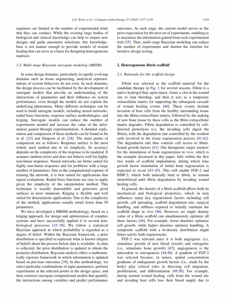
Fig. 4. Hypothetical model of bone growth in response to the therapeutic factors;
(BMP-2), and fibrin density in the fibrin/BMP-2 region of the scaffold (density).
approach best estimates the model of wound healing.
Therefore, numerical optimization on the Bayesian-
derived model would produce better estimates of optimal
values to use in a final therapy design.
Since computational models of wound healing do not
exist, we create a hypothetical model (Fig. 4) that obeys
some simple rules about expected outcomes based upon our
experience and the literature. We emphasize that this model
is an over simplification of nature, but provides a relatively
complex, non-trivial 3D performance surface to demon-
strate our approach. The model obeys the following rules:
†
mag
Uni-modal, normal distributions for single growth
factors: When a single therapeutic growth factor is
delivered, the performance response will have a normal
distribution. If the growth factor concentration is too low,
then there is little effect. If the concentration is too high,
there is a biological feedback mechanism which inhibits
desired cell responses [69]. Furthermore, very high
concentrations of powerful growth factors like BMP-2
can stimulate growth of undesirable cells such as tumor
cells [70].
†
Synergistic effect of multiple growth factors: growthfactors can work synergistically [50], and therefore, the
resulting performance of combined FGF-2 and BMP-2
will be better than for either individually.
†
Bi-modal distribution for fibrin/BMP-2 density: as thefibrin density increases, the time constant for cellular
access to the BMP-2 increases because it takes cells
longer to degrade in this denser portion of the scaffold.
Therefore, the performance begins to improve and reach
a local maximum at a point where the temporal
relationship between cellular access to BMP-2 and
FGF-2 is optimal. A second local maximum is produced
where the net amount of BMP-2, which increases with
density of the fibrin/BMP-2 component, is at an optimal
value as a single factor.
In this simplified model, bone growth is a function of
three parameters: magnitude of the FGF-2 concentration
gradient, BMP-2 concentration, and the fibrin density of the
fibrin/BMP-2 component of the scaffold. In the plots, the
three coordinates (x,y,z) represent these parameters, while
nitude of FGF-2 concentration gradient (FGF-2), BMP-2 concentration

Fig. 5. Bone growth metric versus magnitude of FGf density of the
fibrin/BMP-2 region for fixed BMP-2Z25%.
L.E. Weiss et al. / Computer-Aided Design 37 (2005) 1127–11391134
the shaded colors represent the magnitude of resulting bone
growth metric with red and blue indicating the zones of
maximum and minimum bone growth, respectively. Each
slice shown in the figures corresponds to a filled contour plot
of the behavior of bone growth as a function of two of these
parameters, while the third parameter is kept constant. For
example, Fig. 4c shows the behavior of the bone growth
metric as a function of the magnitude of the FGF-2
concentration gradient and fibrin density of the
fibrin/BMP-2 region at five different values of BMP-2
concentration. Fig. 5 shows a 3D plot of the same data for
BMP-2 concentration fixed at 25% of its range.
To illustrate MBSM, we simulate a set of experiments by
sampling the hypothetical model in Fig. 4. The results of
these experiments are used to construct a surrogate model of
the system response and to select the combination of design
Fig. 6. Projections of the first stag
Fig. 7. First stage Bayesia
parameters for the next stage of experimentation as
discussed below.
For the first set of experiments, we construct a randomized
orthogonal array of 25 sampling points, three variables,
and strength two [71]. Orthogonal arrays have uniform
projection properties that are desirable when exploring high-
dimensional spaces. Fig. 6 shows the projection of this
orthogonal array in planes formed by combinations of the
design variables. Note that even though the orthogonal array
is dispersed in the 3D space that we are exploring, it projects
as a full factorial in each plane.
Once the first stage sampling points are selected, we
simulate the experiments by evaluating the hypothetical
bone growth model for each sampling point. With this data,
we use maximum likelihood estimation to determine the
model parameters that best fit the observed data, thus
uniquely defining the first stage Bayesian surrogate model.
Fig. 7 presents the resulting model for bone growth, using
only 25 experimental points.
Based on the outcomes of the first set of experiments
and the first stage Bayesian model as the prior probability
distribution, we select a second set of 18 experimental
design points using the optimal sampling strategy known as
maximum entropy sampling [72]. The maximum entropy
sampling strategy locates the sample points such that they
maximize the expected information gain, thus reducing the
uncertainty of the predicted response. Fig. 8 shows the
projections of this experimental design in the planes
defined by each pair of design variables. Fig. 8 also
shows the first stage design for comparison purposes. Note
that the distribution of points does not correspond to any
e experimental design, D1.
n surrogate model.

Fig. 9. Projections of the second stage experimental design D2.
Fig. 8. Second stage Bayesian surrogate model.
L.E. Weiss et al. / Computer-Aided Design 37 (2005) 1127–1139 1135
standard experimental design, but rather it is tailored
specifically for the phenomenon we are modeling. Note
also that most of the points are located in the edges of the
design space, mainly in regions that were left unsampled in
the first stage of data collection. This behavior is to be
expected from the maximum entropy sampling technique,
since our knowledge of the response decreases as we move
away from the regions of the space that have been sampled
already.
After determining the experimental design for the second
stage of data collection, we simulate the experiments by
evaluating the hypothetical model at these points, and the
observed responses are used to estimate the new model
parameters via maximum likelihood. Fig. 9 shows the
second stage surrogate model of the response; note the
similarity with the true response shown in Fig. 4, even
though the model is based on experimental data from only
43 samples. To evaluate the performance of the modeling
Fig. 10. Response surface model with line
methodology quantitatively, we calculate the mean relative
error between the Bayesian surrogate model predictions and
the hypothetical bone growth model used to generate the
data. The resulting error after the second stage, averaged
over an array of 100 points distributed uniformly in
the design space, is only 6.73%, with a maximum error of
24.61%.
Next, we compare the MBSM methodology with the
more traditional factorial approach for experimental design
combined with low order polynomials to fit a response
surface to the observed data points. Fig. 10 shows a full
quadratic response surface model built based on a full
factorial design of four values in three variables, with a total
of 64 samples. For this case, the mean relative error is
8.00%, with a maximum error of 40.61%. Note that even
though the response surface model was built with a larger
number of samples (about 50% more samples were used), it
results in larger prediction errors. The main reason for this
ar, quadratic and interaction terms.

Fig. 11. Comparison of modeling methodologies. (a) Hypothetical model for bone growth. (b) Response surface model (64 samples). (c) First stage Bayesian
surrogate model (25 samples). (d) Second stage Bayesian surrogate model (25C18 samples).
L.E. Weiss et al. / Computer-Aided Design 37 (2005) 1127–11391136
behavior is that response surface models are restricted to a
given functional form, usually a second order polynomial on
the input variables. As a result, the models lack flexibility to
adapt to arbitrary shapes of the response over a large
domain. In this application, the underlying model of bone
growth is bi-modal, while the parametric form of the
response surface constrains it to have only one maximum.
Consequently, no matter how many samples are added to the
response surface model, its performance will be poor. On
the other hand, MBSM can adapt to response surfaces of
arbitrary shape, and thus would yield smaller prediction
errors as more samples are added to the model. Furthermore,
due to the use of optimal sampling, multistage Bayesian
models can give smaller prediction errors than response
surface models while requiring a smaller number of
samples, which can yield significant savings in experimental
efforts and costs.
Fig. 11 summarizes our results, comparing the multi-
stage Bayesian surrogate model to the response surface
model with the hypothetical model of Fig. 4. To make
visualization of the models easier, we fixed the concen-
tration of BMP-2 at 25% of its allowed range. Fig. 11
shows surface plots of the bone growth metric as a
function of the magnitude of the FGF-2 concentration
gradient and fibrin density of the fibrin/BMP-2 component
of the scaffold. Note the similarity between the surrogate
models (Fig. 11c and d) with the hypothetical model for
bone growth (Fig. 11a). Note also the improvement of
the model from the first stage (Fig. 11c) to the second
stage (Fig. 11d).
5. Conclusion
Biologically inspired scaffold designs for tissue engin-
eering applications can be built with SFF processes such as
the new fibrin-based printing system described in this
paper. However, SFF also enables the space of design
possibilities to expand dramatically, making it impractical
to test experimentally all combinations of design parameter
values using standard factorial analysis. To address this
problem, we present a computer-aided, multi-stage Baye-
sian surrogate modeling approach that permits us to obtain
more accurate models with fewer samples than would be
required using factorial analysis. In addition to decreasing
the number of samples required, models built using the
Bayesian surrogate methodology can be expanded and
refined over time. We showed how this methodology could
be applied to heterogeneous scaffold designs. As an
example, Bayesian versus traditional factorial design
methods were compared to estimate response surface
models for a simulated computer model of bone regener-
ation. The Bayesian method estimated the true surface
within a mean relative prediction error of 6.73% and a
maximum error of 24.61% compared with 8.00 and
40.61% for the factorial approach. Moreover, the

L.E. Weiss et al. / Computer-Aided Design 37 (2005) 1127–1139 1137
Bayesian-derived surface required only half as many
experimental data points as the factorial approach to
achieve these results. This capability will be particularly
important for realizing next-generation scaffold designs
and for shortening the timeline and reducing the expenses
required to develop new therapies.
Acknowledgements
The authors gratefully acknowledge the funding of
the Office of Naval Research (Grant no. N000140110766),
the National Science Foundation (Grants no. CTS-0210238,
CTS-0103082, and DMI-9800565), the National Institutes
of Health (Grant no. 1 R01 EB00 364-01), the Pennsylvania
Infrastructure Technology Alliance (PITA), a partnership of
Carnegie Mellon, Lehigh University and the Common-
wealth of Pennsylvania’s Department of Community and
Economic Development (DCED), the Health Resources and
Services Administration (Grant no. 1C76 HF 00381-01),
and the Scaife Foundation. We wish to thank Aventis
Behring, L.L.C. (King of Prussia, PA) for their generous
gift of lyophilized human fibrinogen and thrombin, and
Matthews International Corp. (Pittsburgh, PA) for their
generous donation of inkjet solenoid valves. We also
acknowledge Dr Jeffrey Hollinger, Director of The Bone
Tissue Engineering Center at Carnegie Mellon, for his
insight on bone regeneration; Mr Larry Schultz and Dr Jason
Smith for their assistance in the fabrication of matrices; and,
Dr Greg Fisher for his assistance in imaging the scaffolds.
References
[1] Hollinger JO, Kleinschmidt JC. The critical size defect as an
experimental model to test bone repair materials. J Craniofac Surg
1990;1:60–8.
[2] Schmitz JP, Hollinger JO. The critical size defect as an experimental
model for craniomandibulofacial nonunions. Clin Ortho Rel Res
1986;205:299–308.
[3] Weiss L. Process overview, Analytical chapters NSF sponsored
JTEC/WTEC panel report on rapid prototyping in Europe and Japan.
International Technology Research Institute at Loyla College
1997;5–20.
[4] Kim SS, Utsunomiya H, Koski JA, Wu BM, Cima MJ, Sohn J,
Mukai K, Griffith LG, Vacanti JP, et al. Survival and function of
hepatocytes on a novel three-dimensional synthetic biodegradable
polymer scaffold with an intrinsic network of channel. Ann Surg
1998;228:8–13.
[5] Levy RA, Chu TM, Halloran JW, Feinberg SE, Hollister S. CT-
generated porous hydroxyapatite orbital floor prosthesis as a prototype
bioimplant. AJNR Am J Neuroradiol 1997;18:1522–5.
[6] Wang F, Shor L, Darling A, Khalil S, Sun W, Guceri S, Lau A.
Precision extruding deposition and characterization of cellular poly-e-
caprolactone tissue scaffolds. In Solid freeform fabrication sym-
posium, (Austin, Texas 2003;573–84.
[7] Kachurin AM, Stewart RL, Church KH, Warren WL, Fischer JP,
Mikos AG, Kraeft S, Chen L, et al. Direct-write construction of tissue-
engineered scaffolds. Mater Res Symp.: Materials Research Society;
2002.
[8] Das S, Hollister SJ, Flanagan C, Adewunmi A, Bark K, Chen C,
Ramaswamy K, Rose D, Widjaja E, et al. Computational design,
freeform fabrication and testing of nylon-6 tissue engineering
scaffolds. In solid freeform fabrication symposium. Auting: Univer-
sity of Texas; 2002 p. 9–16.
[9] Cooke MN, Fisher JP, Dean D, Rimnac C, Mikos AG. Use of
stereolithography to manufacture critical-sized 3D biodegradable
scaffolds for bone ingrowth. J Biomed Mater Res 2003;64B:
65–9.
[10] Vozzi G, Previti MS, De Rossi D, Ahluwalia A. Microsyringe-based
deposition of two-dimensional and three-dimensional polymer
scaffolds with a well-defined geometry for application to tissue
engineering. Tissue Eng 2003;8:1089–98.
[11] Cornejo I, McNulty TF, Lee S, Bianchi E, Tenhuisen K, Janas V,
Danfroth S, Safari A, et al. Development of bioceramic tissue
scaffolds via FDC. Ceramic Trans 2000;110:183–95.
[12] Zein I, Hutmacher DW, Tan KC, Teoh SH. Fused deposition
modeling of novel scaffold architectures for tissue engineering
applications. Biomaterials 2002;23:1169–85.
[13] Morissette SL, Lewis JA, Cesarano J, Dimos D, Baer T. Solid
freeform fabrication of aqueous alumina-poly(vinyl alcohol) gel
casting suspensions. J Am Ceram Soc 2000;83:2409–16.
[14] Lee G, Barlow JW. Selective laser sintering of bioceramic materials
of implants. In solid freeform fabrication symposium. Austin:
University of Texas; 1993 (p. 376–80).
[15] Lee G, Barlow J. Selective laser sintering of calcium phosphate
powders. In Solid freeform fabrication symposium 1994 (The
University of Texas at Austin), pp. 191–7.
[16] Leong KF, Phua KK, Chua CK, Du ZH, Teo KO. Fabrication of
porous polymeric matrix drug delivery devices using the selective
laser sintering technique. Proc Inst Mech Eng, [H] 2001;215:
191–201.
[17] Weiss L, Szem J. Assembled scaffolds for three dimensional cell
culture and tissue regeneration. Patent no. 6,143,293. USA: Carnegie
Mellon and University of Pittsburgh; 2000.
[18] Weiss L, Prinz F. Novel applications and implementations of
shape deposition manufacturing.: Office of Naval Research; 1998.
L(3).
[19] Weiss L, Merz R, Prinz F, Neplotnik G, Padmanabhan P, Schultz L,
Ramaswami K, et al. Shape deposition manufacturing of hetero-
geneous structures. SME J Manuf Syst 1997;16:239–48.
[20] Weiss L. NSF workshop on design methodologies for solid freeform
fabrication. Pittsburgh, PA: Carnegie Mellon University; 1995. NSF
96–216.
[21] Weiss L. Tissue engineering: solid freeform fabrication of scaffolds.
Sci Med 2002;8:6–7.
[22] Cima M, Sachs E, Cima L, Yoo J, Khanuja S, Borland S, Wu B,
Giordano R, et al. Computer-derived microstructures by 3D. Solid
freeform fabrication symposium 1994 (The University of Texas
at Austin), p. 181–190.
[23] Wilson Jr WC, Boland T. Cell and organ printing 1: protein and cell
printers. Anat Rec 2003;272A:491–6.
[24] Mironov V, Boland T, Trusk T, Forgacs G, Markwald RR. Organ
printing: computer-aided jet-based 3D tissue engineering. Trends
Biotechnol 2003;21:157–61.
[25] Boland T, Mironov V, Gutowska A, Roth EA, Markwald RR. Cell and
organ printing 2: fusion of cell aggregates in three-dimensional gels.
Anat Rec 2003;272A:497–502.
[26] Ringeisen BR, Kim H, Young HD, Spargo BJ, Auyeung RCY.
Cell-by-cell construction of living tissue. Mat Res Symp.: Materials
Research Society; 2002.
[27] Marquez GJ, Renn MJ, Miller WD. Aerosol-based direct-write of
biological materials for biomedical applications. Mat Res Soc Symp
Proc.: Materials Research Society; 2002.
[28] Pitts J, Campagnola P, Epling G, Goodman S. Submicron multiphoton
free-form fabrication of proteins and polymers: studies of reaction
L.E. Weiss et al. / Computer-Aided Design 37 (2005) 1127–11391138
efficiencies and applications in sustained release. Macromolecules
2000;33:1514–23.
[29] Klebe RJ. Cytoscribing: a method for micropositioning of cells and
the construction of two- and three-dimensional synthetic tissues.
Exp Cell Res 1988;179:362–73.
[30] Klebe RJ. Apparatus for the precise positioning of cells. Patent no.
5,108,926 1992.
[31] Sun W, Darling A, Starly B, Nam J. Computer aided tissue
engineering, part I: overview, scope, challenges. J Biotechnol Appl
Biochem 2004;39:29–47.
[32] Sun W, Starly B, Darling A, Gomez C. Computer aided tissue
engineering, part II: application to biomimetic modeling and design of
tissue scaffolds. J Biotechnol Appl Biochem 2004;39:49–58.
[33] Jin R, Chen W, Simpson TW. Comparative studies of metamodeling
techniques under multiple modeling criteria. Struct multidisciplinary
optimization 2001;23:1–13.
[34] Simpson TW, Peplinski JD, Koch PN, Allen JK. Metamodels for
computer-based engineering design: survey and recommendations.
Eng Comput 2001;17:129–50.
[35] Osio IG, Amon CH. An engineering design methodology with
multistage Bayesian surrogates and optimal sampling. Res Eng Des
1996;8:189–206.
[36] Amon CH, Finger S. Combining experimental and statistical methods
for quality improvement of microcasting in shape deposition
manufacturing. Proceedings of the 1998 NSF design and manufactur-
ing grantees conference. Mexico: Monterrey; 1998.
[37] Pacheco JE, Amon CH, Finger S. Flexible multistage Bayesian
models for use in conceptual design. Fourteenth international ASME
conference on design theory and methodology. Canada: Montreal;
2002.
[38] Leoni N, Amon CH. Bayesian surrogates for integrating numerical,
analytical and experimental data: application to inverse heat transfer
in wearable computers. IEEE transactions on components and
packaging technol 2000;23:23–32.
[39] Doraiswamy S, Bayesian S. Bayesian analysis in engineering model
assessment. ASME design engineering technical conferences. MD:
Baltimore; 2000.
[40] Clarke HJ, Jinnah RH, Lennox D. Osteointegration of bone graft in
porous-coated total hip arthroplasty. Clin Orthop Rel Res 1990;258:
160–7.
[41] Rifkin DB, Mazzieri R, Munger JS, Noguera I, Sung J. Proteolytic
control of growth factor availability. Apmis 1999;107:80–5.
[42] Campbell PG, Wines K, Yanosick TB, Novak JF. Binding and
activation of plasminogen on the surface of osteosarcoma cells. J Cell
Physiol 1994;159:1–10.
[43] Wang JS. Basic fibroblast growth factor for stimulation of bone
formation in osteoinductive or conductive implants. Acta Orthop
Scand 1996;l269:1–33.
[44] Wang J, Aspenberg P. Basic fibroblast growth factor enhances bone-
graft incorporation: dose and time dependence in rats. J Orthop Res
1996;34:316–23.
[45] Winn SR, Schmitt JM, Buck D, Hu Y, Grainger D, Hollinger JO.
A tissue engineered bone biomimetic to regenerate calvarial
critical-sized defects in athymic rats. J Biomed Mater Res 1999;
45:414–21.
[46] Bensaid W, Triffitt JT, Blanchat C, Oudina K, Sedel L, Petite H. A
biodegradable fibrin scaffold for mesenchymal stem cell transplan-
tation. Biomaterials 2003;24:2497–502.
[47] Bikfalvi A, Klein S, Pintucci G, Rifkin DB. Biological roles of
fibroblast growth factor-2. Endocr Rev 1997;18:26–45.
[48] Wang JS, Aspenberg P. Basic fibroblast growth factor infused at
different times during bone graft incorporation. Titanium chamber
study in rats. Acta. Orthop. Scand. 1996;67:229–36.
[49] Tabata T. Genetics of morphogen gradients. Nat Rev Genet 2001;2:
620–30.
[50] Einhorn TA. In: Brighton CT, Freidlaender GE, Lane JM, editors.
Enhancement of fracture healing by molecular or physical means:
an overview. Bone formation and repair. Rosemont, IL: AAOS;
1994.
[51] Saltzman WM, Olbreicht WL. Building drug delivery into tissue
engineering. Nat Rev Drug Discovery 2002;1:177–86.
[52] Sakiyama SE, Schense JC, Hubbell JA. Incorporation of heparin-
binding peptides into fibrin gels enhances neurite extension: an
example of designer matrices in tissue engineering. FASEB J 1999;
13:2214–24.
[53] Richardson TP, Peters MC, Ennett AB, Mooney DJ. Polymeric
system for dual growth factor delivery. Nat Biotechnol 2001;19:
1029–34.
[54] Bosch C, Melsen B, Vargervik K. Guided bone regeneration in
calvarial bone defects using polytetrafluoroethylene membranes. Cleft
Palate Craniofac J 1995;32:311–7.
[55] Wang J, Glimcher MJ. Characterization of matrix-induced osteogen-
esis in rat calvarial bone defects: origins of bone-forming cells. Calcif
Tissue Int 1999;65:486–93.
[56] Clark RA. Fibrin wound healing. Ann N Y Acad Sci 2001;936:
355–67.
[57] Wozney JM. The potential role of bone morphogenetic proteins in
periodontal reconstruction. J Periodontol 1995;66:506–10.
[58] Mosesson MW. The assembly and structure of the fibrin clot. Nouv
Rev Fr Hematol 1992;34:11–16.
[59] Sahni A, Odrljin T, Francis CW. Binding of basic fibroblast growth
factor to fibrinogen and fibrin. J Biol Chem 1998;273:7554–9.
[60] Jockenhoevel S, Zund G, Hoerstrup SP, Chalabi K, Sachweh JS,
Demircan L, Messmer BJ, Turina M, et al. Fibrin gel – advantages of a
new scaffold in cardiovascular tissue engineering. Eur J Cardiothorac
Surg 2001;19:424–30.
[61] Herbert CB, Nagaswami C, Bittner GD, Hubbell JA, Weisel JW.
Effects of fibrin micromorphology on neurite growth from dorsal root
ganglia cultured in three-dimensional fibrin gels. J Biomed Mater Res
1998;40:551–9.
[62] Lindley DV. Bayesian statistics—a review. Philadelphia: SIAM ed.;
1972.
[63] Pacheco JE, Amon CH, Finger S, Pacheco JE, Amon C, Finger S.
Bayesian surrogates applied to conceptual stages of the engineering
design process. ASME J Mech Des 2003;125:664–72.
[64] Leoni N. Integrating information sources into global models: a
surrogate methodology for product and process development
Mechanical Engineering, PhD Thesis, Carnegie Mellon University,
Pittsburgh, PA; 1999.
[65] Pacheco JE, Amon CH, Finger S. Developing Bayesian surrogates for
use in preliminary design. ASME design engineering technical
conference, theory and methodology 2001.
[66] Pacheco JE. A methodology for surrogate model building in the
engineering design process. PhD Thesis, Department of Mechan-
ical Engineering, Carnegie Mellon University, Pittsburgh, USA;
2003.
[67] Pacheco JE, Amon CH, Finger S. Incorporating information from
replications into Bayesian surrogate models. ASME international
design engineering technical conferences 2003.
[68] Romero D, Amon CH, Finger S, Verdinelli I. Multi-stage Bayesian
surrogates for the design of time-dependent systems. ASME 2004
international design engineering technical conferences. Salt Lake
City, USA: American Society of Mechanical Engineers (ASME);
2004.
[69] Battegay EJ, Raines EW, Seifert RA, Bowen-Pope DF, Ross R.
TGF-beta induces bimodal proliferation of connective tissue cells
via complex control of an autocrine PDGF loop. Cell 1990;63:
515–24.
[70] Poynton AR, Lane JM. Safety profile for the clinical use of bone
morphogenetic proteins in the spine. Spine 2002;27(1):S40–S8.
[71] Owen AB. Orthogonal arrays for computer experiments, integration
and visualization. Statistica Sinica 1992;2:439–52.
[72] Shewry MC, Wynn HP. Maximum entropy sampling. J Appl Stat
1987;14:165–70.
ided
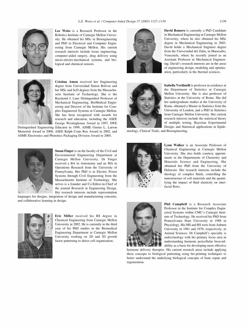
L.E. Weiss et al. / Computer-ALee Weiss is a Research Professor in the
Robotics Institute of Carnegie Mellon Univer-
sity. He obtained his MSc in Bioengineering
and PhD in Electrical and Computer Engin-
eering from Carnegie Mellon. His current
research interests include tissue engineering,
computer-aided surgery, drug delivery using
micro-electro-mechanical systems, and bio-
logical and chemical sensors.
Cristina Amon received her Engineering
degree from Universidad Simon Bolivar and
her MSc and ScD degrees from the Massachu-
setts Institute of Technology. She is the
Raymond J. Lane Distinguished Professor of
Mechanical Engineering, BioMedical Engin-
eering and Director of the Institute for Com-
plex Engineered Systems at Carnegie Mellon.
She has been recognized with awards for
research and education, including the ASEE
George Westinghouse Award in 1997, SWE
Distinguished Engineering Educator in 1999, ASME Gustus L. Larson
Memorial Award in 2000, ASEE Ralph Coats Roe Award in 2002, and
ASME Electronics and Photonics Packaging Division Award in 2004.
Susan Finger is on the faculty of the Civil and
Environmental Engineering Department at
Carnegie Mellon University. Dr Finger
received a BA in Astronomy and an MA in
Operations Research from the University of
Pennsylvania. Her PhD is in Electric Power
Systems through Civil Engineering from the
Massachusetts Institute of Technology. She
serves is a founder and Co-Editor-in-Chief of
the journal Research in Engineering Design.
Her research interests include representation
languages for designs, integration of design and manufacturing concerns,
and collaborative learning in design.
Eric Miller received his BS degree in
Chemical Engineering from Carnegie Mellon
University in 2002. He is currently in the third
year of his PhD studies in the Biomedical
Engineering Department at Carnegie Mellon
University working on 2D and 3D growth
factor patterning to direct cell organization.
David Romero is currently a PhD Candidate
in Mechanical Engineering at Carnegie Mellon
University, where he also obtained his MSc
degree in Mechanical Engineering in 2003.
David holds a Mechanical Engineer degree
from the Universidad del Zulia, in Maracaibo,
Design 37 (2005) 1127–1139 1139
Venezuela, where he recently joined as an
Assistant Professor in Mechanical Engineer-
ing. David’s research interests are in the areas
of engineering design, modeling and optimiz-
ation, particularly in the thermal sciences.
Isabella Verdinelli is professor in residence at
the Department of Statistics at Carnegie
Mellon University. She is also professor of
Statistics at the University of Rome. She did
her undergraduate studies at the University of
Rome, obtained a Master in Statistics from the
University of London, and a PhD in Statistics
from Carnegie Mellon University. Her current
research interests include the statistical theory
of multiple testing, Bayesian Experimental
Design, and Statistical applications in Epide-
miology, Clinical Trials, and Bioengineering.
Lynn Walker is an Associate Professor of
Chemical Engineering at Carnegie Mellon
University. She also holds courtesy appoint-
ments in the Departments of Chemistry and
Materials Science and Engineering. She
obtained her PhD from the University of
Delaware. Her research interests include the
rheology of complex fluids, controlling the
nanostructure of soft materials and the quanti-
fying the impact of fluid elasticity on inter-
facial flows.
Phil Campbell is a Research Associate
Professor in the Institute for Complex Engin-
eered Systems within CMU’s Carnegie Insti-
tute of Technology. He received his PhD from
Pennsylvania State University in 1988 in
Physiology. His MS and BS were from Auburn
University in 1981 and 1978, respectively, in
Animal Sciences. Dr Campbell’s specialty is
endocrinology with his primary focus area in
understanding hormone pericellular bioavail-
ability as a basis for developing more effective
hormone delivery therapies. His current research areas include applying
these concepts to biological patterning using bio-printing techniques to
better understand the underlying biological concepts of bone repair and
regeneration.


![Bayesian computer-aided experimental design of ..../lew/PUBLICATION PDFs/TISSUE... · 19]. For tissue engineering applications, we proposed the extension of SFF methodology to build](https://img.pdfslide.us/doc/110x75/5f913745a0564336b6453b98/bayesian-computer-aided-experimental-design-of-lewpublication-pdfstissue.jpg)