Embed Size (px)
Citation preview
BATTERY -SUPERCAPACITOR HYBRID
ENERGY STORAGE SYSTEMSponsored by
KELD LLC
Team 10
Manager: Marvell Mukongolo
Webmaster: Chi-Fai Lo
Documentation: Michael Andrew Kovalcik
Presentation/Lab Manager: Jamal Xavier Adams
Facilitator: Dr. Fang Zheng Peng

Executive Summary
The project undertaken by design team ten is to design and build a “Battery-
Supercapacitor Hybrid Energy Storage System” for HEV and renewable power generation. The
parameters for a successful project is a system will have a nominal 48 Volts and be able to power
a pulsating load with the following characteristics: 48 Volts 20%, one kilowatt peak power for
18 seconds over every two minutes with an average of 200W over the two minute period. The
system has been designed to run over a 30 minute period without being recharged by an external
source. Super capacitors are used to provide 1kW of power for 18 seconds during each cycle. We
have placed in our system a super capacitor module that can handle over 18 seconds if necessary.
We constructed a 14 cell lithium ion battery (51.8 Volts nominal) equipped with a protection
circuit module. Active circuit components such as solid state relays are used to control the flow
of power between the power supplies and the load. This system is efficient because it reduces the
overall cost and weight when placed against other systems that perform the same functions.
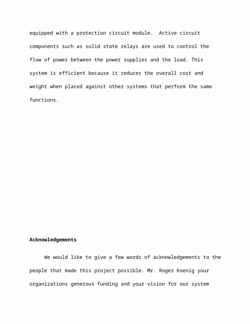
Acknowledgements
We would like to give a few words of acknowledgements to the people that made this
project possible. Mr. Roger Koenig your organizations generous funding and your vision for our
system made our journey of discovery possible. Dr. Peng and Dr. Goodman both of you provided
impeccable guidance. The specialists at the ECE shop and Mrs. Roxanne Peacock provided great
advice and services during critical times of the last semester.

Table of Contents

Introduction
The rising cost of energy combined with increasing awareness and acceptance of global
warming, has served as kindling for the forge that is now the white-hot “green” technology
sector. The field of Electrical Engineering is deeply affected by the push for cleaner energy and
transportation. Hybrid vehicles have emerged as a possible solution some of the world energy
ailments. Even though the hybrid saves fuel, it has its flows. The battery is made of highly
reactive substances, is very expensive, heavy, and difficult to replace. For the hybrid electric
vehicle to become a complete solution, these flows have to be addressed. The advent of new,
high-energy storage capacitors, and lighter rechargeable batteries, with greater energy density,
has allowed new developments in the clean energy sector. Creating and utilizing new
technologies is at the forefront of modern engineering and is sure to create many jobs, driving
our economy, our careers, and our vehicles for the foreseeable future.
Background
Rechargeable batteries such as lithium ion batteries are idea energy sources because they
save the cost of replacement and they alleviate the environmental damage of disposable batteries.
Today’s Hybrid Electrical Vehicles (HEV) for example use rechargeable batteries with gas
powered engines to provide power to a vehicle. This system uses the battery as a primary source
of energy and gasoline as a backup in order to achieve greater gas mileage. The problem with
this system is the battery has no buffer between it and the load (in this case the every system in
the car). Without a buffer the battery is susceptible to damage and battery life is greatly reduced.
The preferable operation of a rechargeable battery would be a constant load drawing average to
minimum current. While using a battery in an HEV by itself, the battery is subjected to changes
in the amount of power it generates to and receives from the load. Since most rechargeable
batteries have low power densities their life spans are reduced by the constant erratic oscillation
in demand. A solution to this problem can be a super capacitor/ battery system, with the super
capacitors acting as a buffer. Super capacitors make suitable buffers because they have high
power densities making it possible for them to handle erratic oscillations in demand without
sustaining any damages.
The objective of this project is to develop an energy storage system that is suitable for use
in HEV and can be used for remote or backup energy storage systems in absence of a working
power grid. In order to get the highest efficiency from this system, super capacitors will be used
in parallel with the battery and a pulsed load. The final product should use active circuit
components to influence performance and efficiency in accordance with a varying load. The load
will be programmed to simulate a pulsating energy demand. The goal is create an efficient
system with an overall reduction in cost, size, and weight.
Objective:
The objective of this project is to develop an energy storage system that is suitable for use
in Hybrid Electrical Vehicles (HEV) and can be used for remote or backup energy storage
systems in absence of a working power grid. In order to get the highest efficiency from this
system, super capacitors will be used in parallel with the battery and a pulsed load. The final
product should use active circuit components to influence performance and efficiency in
accordance with a varying load. The load will be programmed to simulate a pulsating energy
demand. The goal is create an efficient system with an overall reduction in cost, size, and weight.
Super Capacitors
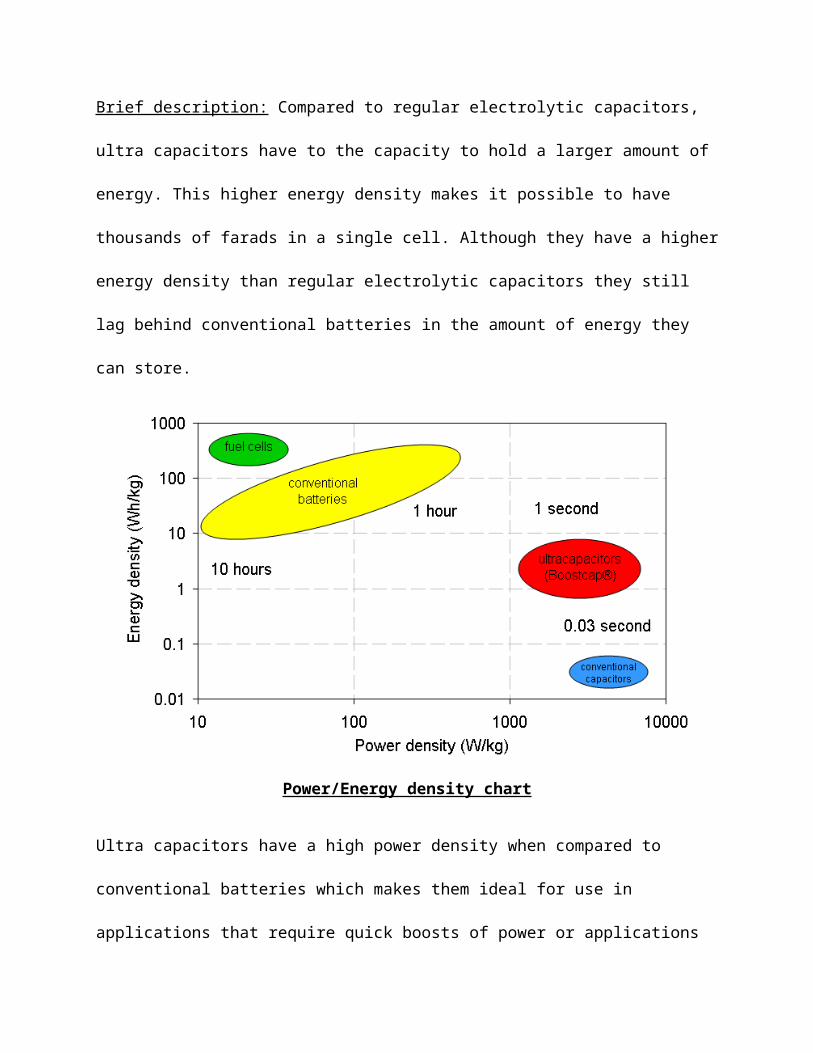
Brief description: Compared to regular electrolytic capacitors, ultra capacitors have to the
capacity to hold a larger amount of energy. This higher energy density makes it possible to have
thousands of farads in a single cell. Although they have a higher energy density than regular
electrolytic capacitors they still lag behind conventional batteries in the amount of energy they
can store.
Power/Energy density chart
Ultra capacitors have a high power density when compared to conventional batteries which
makes them ideal for use in applications that require quick boosts of power or applications that
require a power supply to receive a large amount of power in a short amount of time for example
regenerative braking. A major drawback to ultra capacitors is there inability to handle higher
voltages per cell unit and their voltage decays linearly making them highly unstable for use as a
primary energy supply.
Chapter 2
Tasks:
(1) Design a battery to provide the average power to the load for at least 20 minutes
(2) Design a supercapacitor to provide the pulse power to the load
(3) Design and build a hybrid structure (or circuit configuration) of the battery and
supercapacitor to provide needed power to the load
(4) Design and build a programmable load to simulate the pulsating load
(5) Test and demonstrate the hybrid energy storage system to prove that the constant
power is from the battery and the pulse power of the load is from the supercapacitor
(6) Provide final report and suggestions to improve/optimize the system
Design Specifications:
For safety reasons the hybrid energy storage system should be 48 volt nominal
and able to power a pulsating load with the following characteristics: 48 volt ± 20%, 1
KW peak power for 18 seconds over every 2 minutes (consider almost 0 kW for the
remaining 102 seconds of every 2 minute period). The energy storage system should be
able to provide at least 20 minutes of power to the load. The system will be used for
vehicle power storage and as an alternative destination for renewable energy output that
does not directly connect to the power grid. This design will be on a smaller scale than
actual systems used in Hybrid Electric Vehicles and renewable energy storage systems.
Project Deliverables:
• A working unit of a 1 KW hybrid energy storage system
• A working unit of 1 KW programmable load
• A final report of test results and suggestions to improve and optimize the system
Our project description was open ended, which left us imagining the different
possibilities that were available for such a necessary energy system. After conferring with our
facilitator and sponsor about the project we got some closure. Once we realized what it is
exactly we had to do, we now had to double check to make sure we correct in our hypotheses.
This is when we involved the Voice of the Customer to develop the Customer Critical
Requirements. We listened to our facilitator’s and sponsor’s needs as we asked them probing
questions. We learned that a battery-supercapacitor hybrid system needed to be developed to
produce pulse of power for 18 seconds every 2minutes for twenty minutes.
So now we listed the parts necessary for the project, and described each of the
components. Once we finished describing these parts we are able to determine there functions,
and use those functions to make our Fast Diagram. In looking at our fast diagram, we identified
the subsystems as recharging and charging our system. The recharging aspect of the system isn’t
that difficult because all we need to buy is a battery charger, and the supercapacitor will be
recharged by the battery. The discharging aspect will be the most complicated part. For this is
where the actual design of the system comes into play. Here we have to break the system down
component by component to accurately get project design the way we want it. To ensure we are
on the right track we will have weekly meetings with our facilitator updating him on progress
and discoveries made.
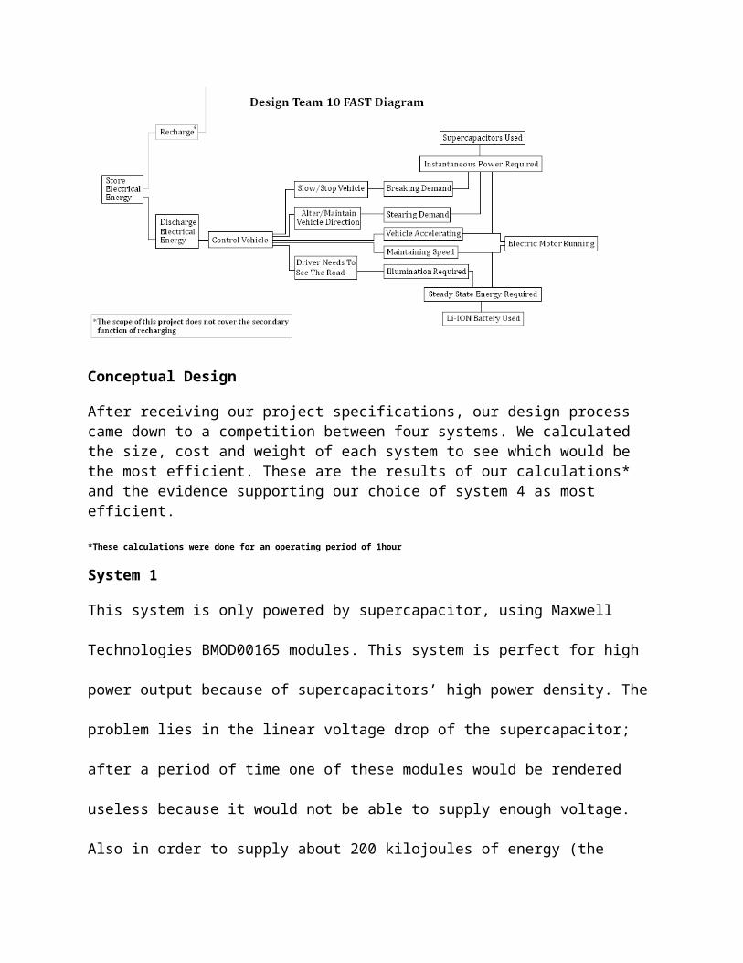
Conceptual Design
After receiving our project specifications, our design process came down to a competition between four systems. We calculated the size, cost and weight of each system to see which would be the most efficient. These are the results of our calculations* and the evidence supporting our choice of system 4 as most efficient.
*These calculations were done for an operating period of 1hour
System 1
This system is only powered by supercapacitor, using Maxwell Technologies BMOD00165
modules. This system is perfect for high power output because of supercapacitors’ high power
density. The problem lies in the linear voltage drop of the supercapacitor; after a period of time
one of these modules would be rendered useless because it would not be able to supply enough
voltage. Also in order to supply about 200 kilojoules of energy (the amount of energy needed for
540 seconds at 1kW or the 9 minutes total of the hour) without recharging, a capacitance of 783F
is needed. This capacitance would require five BMOD00165 modules which cost $2240 a piece.
This design was the first of the board because of its unreasonably high cost.
System 2
This system was battery powered, using 3.7V (21Ah) Lithium Ion Polymer batteries. In order to
provide a full kilowatt of power this system would have been required to operate at 1C. At 1C
one milliamp hour battery will provide 1milliamp for one hour if discharged properly. This
system would require fourteen 3.7V Lithium Ion Polymer cells output at 1C for each peak
period. Rechargeable batteries are not well equipped to handle this type of operation; quick
discharges of current require high power densities, something that rechargeable batteries lack.
System 3
This system was battery powered, using 3.7V (21Ah) Lithium Ion Polymer batteries in parallel
with a supercapacitor array, using Maxwell Technologies BMOD00165 modules. Without a
microcontroller this system would use a delicate balancing of the voltage across the batteries and
supercapacitors to have a mixed power output. This system cuts the amount of current needed
from the batteries in half. Also the amount of capacitance needed would be cut in half. But this
only brings us down to 400F (three BMOD00165 modules), once again at a cost of $2240 a piece
this design was not feasible under our budget and it failed every efficiency tests.
System 4
This system was battery powered, using 3.7V (21Ah) Lithium Ion Polymer batteries in parallel
with a supercapacitor array, using Maxwell Technologies BMOD00165 modules. The major
difference between system 4 and system 3 is the active components in the circuit which switch
the power flow between the sources (batteries and supercapacitors) and the loads. Using solid
state relays and a relay controller we would be able to use the battery as a charger for the
supercapacitors, and the supercapacitors would then be used to provide power to the load. In this
case battery life is spared as well as the detrimental effects of a pulse signal are avoided by the
battery. In this system only an 83F module would be needed which costs less than $2000. With
this configuration all three measures of efficiency are met (reduced cost, size and weight). This
system is explained with greater detail in chapter 3.
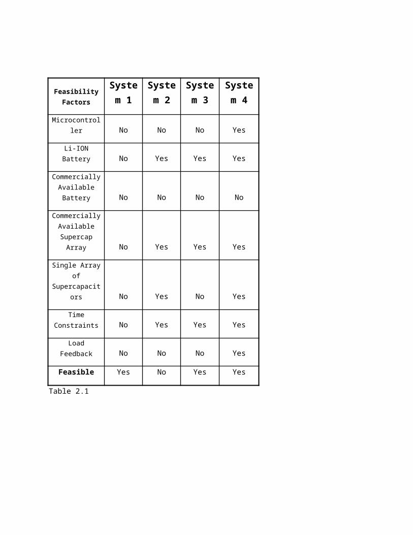
Feasibility Factors
System 1
System 2
System 3
System 4
Microcontroller No No No Yes
Li-ION Battery No Yes Yes Yes
Commercially Available Battery No No No No
Commercially Available
Supercap Array No Yes Yes Yes
Single Array of Supercapacitors No Yes No Yes
Time Constraints No Yes Yes Yes
Load Feedback No No No Yes
Feasible Yes No Yes Yes
Table 2.1
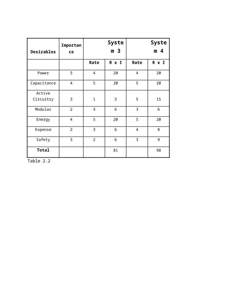
DesirablesImportanc
e
System 3
System 4
Rate R x I Rate R x I
Power 5 4 20 4 20
Capacitance 4 5 20 5 20
Active Circuitry 3 1 3 5 15
Modular 2 3 6 3 6
Energy 4 5 20 5 20
Expense 2 3 6 4 8
Safety 3 2 6 3 9
Total 81 98
Table 2.2
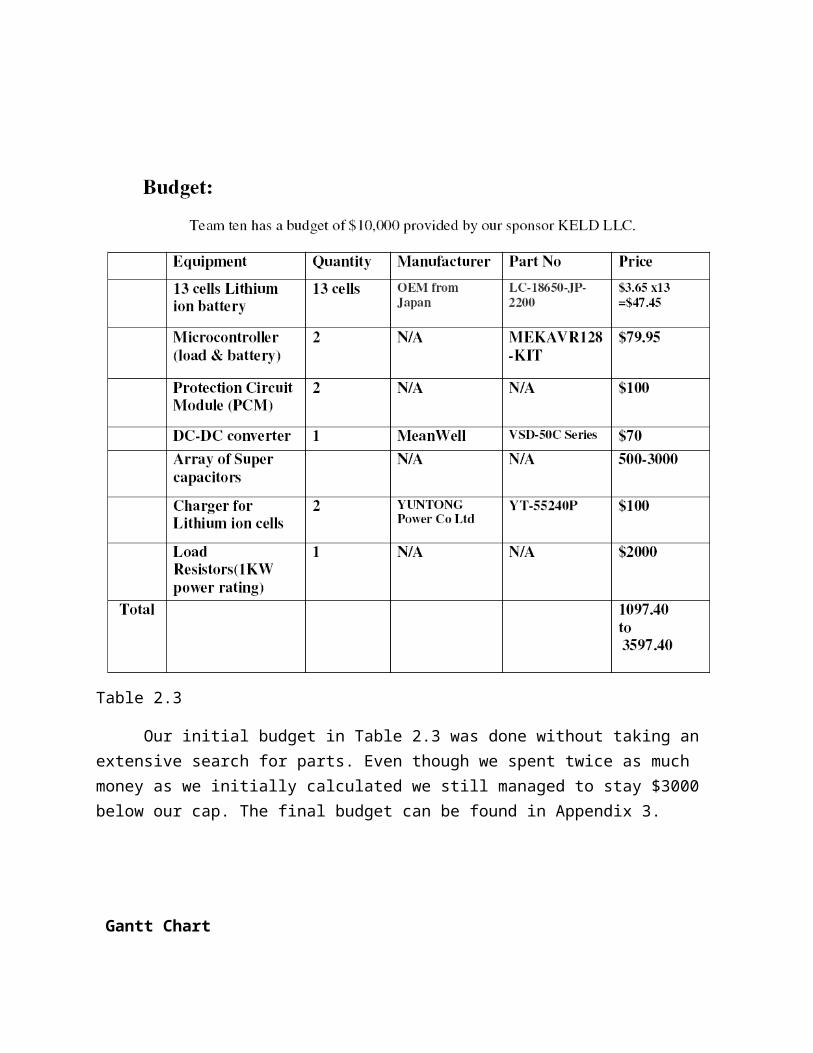
Table 2.3
Our initial budget in Table 2.3 was done without taking an extensive search for parts. Even though we spent twice as much money as we initially calculated we still managed to stay $3000 below our cap. The final budget can be found in Appendix 3.
Gantt Chart
Truthfully we did not receive our project specifications until the day before the first Gantt chart
was due. This is not a good indicator of the planning that went on after the project specifications
were given to us. For the final Gantt chart please refer to Appendix 3.
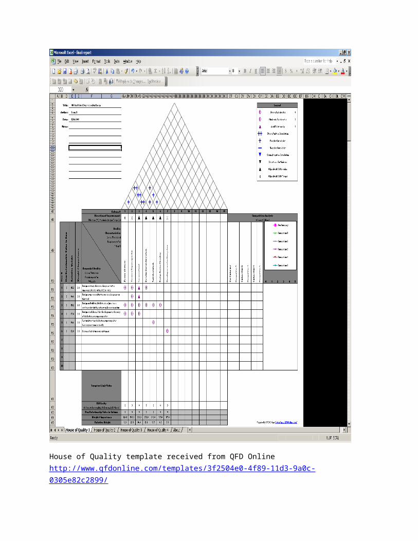
House of Quality template received from QFD Online http://www.qfdonline.com/templates/3f2504e0-4f89-11d3-9a0c-0305e82c2899/
Technical description of work performed
In order to build and test our energy storage system a fourteen cell battery module had to
be constructed and attached to a protection circuit module (PCM). A battery for our needs could
not be found on the market. We were however able to find a 48V super capacitor module that
was prepackaged with a PCM that suited out requirements. For a controllable load we used solid
state relays and a programmable load to control the power flow to the battery. The following is a
detailed description of each component used in this system.
Battery
For the battery module we constructed we used fourteen 3.7V lithium ion polymer
batteries. We calculated we would need 21 Amp-hours to power a 1000W load (it is usually a
good idea to add 10 to 20% to the calculated amp hour result). This module was capable of such
an output.
Assembly: Once you have received the cells and the PCM it is a simple matter of soldering the
cells together in series and then connecting it to the PCM as shown in Figure 4.
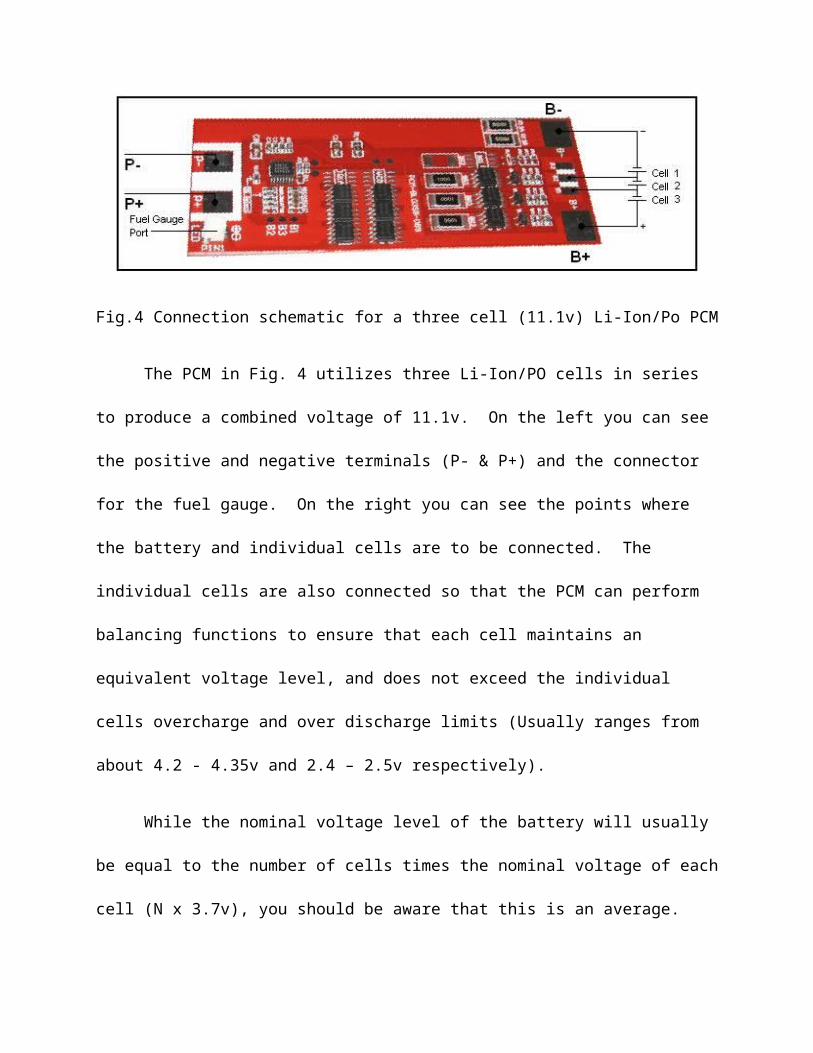
Fig.4 Connection schematic for a three cell (11.1v) Li-Ion/Po PCM
The PCM in Fig. 4 utilizes three Li-Ion/PO cells in series to produce a combined voltage
of 11.1v. On the left you can see the positive and negative terminals (P- & P+) and the
connector for the fuel gauge. On the right you can see the points where the battery and
individual cells are to be connected. The individual cells are also connected so that the PCM can
perform balancing functions to ensure that each cell maintains an equivalent voltage level, and
does not exceed the individual cells overcharge and over discharge limits (Usually ranges from
about 4.2 - 4.35v and 2.4 – 2.5v respectively).
While the nominal voltage level of the battery will usually be equal to the number of cells
times the nominal voltage of each cell (N x 3.7v), you should be aware that this is an average.
The maximum and minimum voltages of the battery will be the number of cells times the
overcharge and over discharge limits respectively. This may or may not be the same number
indicated in the instructions for the PCM you have selected. For the 11.1v system in Fig. 4 the
maximum battery voltage may be calculated to be higher then the PCM specification. This is
fine because the onboard PCM system is also used when charging the battery, so as long as it is
charged through the P+ and P- terminals of the PCM, it will never reach the higher overcharge
and over discharge limits of the cells.
Charging: In order to charge your PCM onboard battery, simply connect the appropriate PCM
terminals to a DC power supply, this ensures that the current level used is in accordance with the
level specified by the manufacturer of the individual battery cells used or the PCM, which ever is
lower.
Maxwell Technologies BMOD0165-48.6V Supercapacitors
The BMOD00165 module was not our first choice for the system but it was the second
best choice. In order to supply 1000W of power for 18 seconds at 48V a capacitor needs a
minimum of 44 Farads.
Module Voltage vs. Time characteristics
An 83F* module would have been able to sustain a voltage between 48.6V and 40V at 1000W
for 18 seconds. Even though we only needed 44F-47F to provide powers, the linear voltage loss
made it necessary to increase the amount of capacitance. Also for cost saving purposes we
decided to create a system which can recharge the ultra capacitor module after every cycle. This
route allows us to save thousands of dollars and as well as reducing the overall mass of the
power plant. In order to have a system that could handle ten cycles on a single charge we would
need a 400 farad module. This would require three 165 farad modules placed in parallel with
each other, the cost of such a module would be around $6000. Using one module for one cycle
saves us over $4000 in total cost. This route also requires the addition of active circuit
components that will switch the flow of power between the battery and the ultra capacitor
module, to the load.

*Richardson Electronics did not have any 83F modules in stock and there was an estimated 6 week wait for delivery. We could not afford to wait 6 weeks for
delivery, so we decided to purchase the 165F module which was not unreasonably higher in price and size.
Chapter 4: Final Test Results
For the final test the system failed to work because of a broken terminal on one of the cells.
During the construction of the battery one of cells was damaged and instead of buying a new one
we tried to fix the battery. Initially the battery module produced 51.8V but after connecting the
relays a resistor on the PCM was destroyed. We measured the voltage coming from the damaged
battery module and the measurement showed one missing cell. At this moment we do not know
what effect the relays had on the damaged battery. Since part of the PCM was burning we
decided to discontinue the testing. The relay controller however worked, it switched the relays on
and off at the exact times we required.
Chapter 5 – Final cost, schedule, summary and conclusions
Final Cost
We were given a budget of $10000 to complete this project. After all the parts were bought we saved $3000. The cost of the parts we needed was more expensive than the initial estimates we made on the preliminary budget.
Summary
Appendix 1
My portion of team tens project was to work on the super capacitor module and
program the relay controller to the load. I was responsible for demonstrating that the
system we chose would be those most efficient through mathematics. For our first
demonstration we were given the task of putting figures together that would show
which system out of four would be the most efficient. I created a report of three systems showing
the weakness and strengths of each system. In the end the hybrid system seemed as the most
efficient in that report. When the time came to purchase the parts for our system, I was given the
task of purchasing the super capacitor module. The system that we chose to make required a
super capacitor module that would need about 400 F in capacitance, after looking at the prices
we realized this was out of our price range. The 48V modules were priced at $1600 to $3000
each depending on capacitance; there was also the option of purchasing three 16V modules and
placing them in series to get 48V, but that route proved to be useless due to the fact that the price
would not have changed very much. Using only one super capacitor module will require the
battery to recharge it after every peak demand cycle. For this process solid state relays will be
Marvell Mukongolo
used to switch the power flow. After couple of back and forth emails to Richardson Electronics
and Maxwell Technologies, I was able to find a voltage/time profile for the 48V super capacitor
modules. For the system a 165 F module was purchased at a price of $2,288, according to the
Maxwell Technologies engineers this module can handle twenty five seconds supplying our peak
load
Appendix 2
Final Gantt chart

Appendix
3


![Battery-Supercapacitor Hybrid Energy Storage · Battery versus Hybrid ... high-energy batteries with supercapacitors [8]. ... Microgrids are the most used application for high power](https://img.pdfslide.us/doc/110x75/5b5b6b2a7f8b9a905c8df9e6/battery-supercapacitor-hybrid-energy-storage-battery-versus-hybrid-high-energy.jpg)