Embed Size (px)
Citation preview

BATTERY MONITOR GP-BMK-50
User Manual
© 2018 Go Power!®
Worldwide Technical Support and Product Information gpelectric.com
Go Power! Headquarters201-710 Redbrick St, Victoria, BC Canada V8T 5J3
MAN_GP-BMK-50_RevE

[page 2] | gpelectric.com
gpelectric.com | [page 3]
1. CONTENTS
2. GETTING STARTED ............................................................................................................... 52.1 BATTERY CAPACITY ............................................................................................. 5
2.2 AUXILIARY INPUT (GP-BMK-50) ........................................................................... 52.3 IMPORTANT COMBINED BUTTON FUNCTIONS ................................................. 6
3. NORMAL OPERATING MODE ............................................................................................... 73.1 READ OUT OVERVIEW ......................................................................................... 73.2 SYNCHRONIZING THE GP-BMK-50 ..................................................................... 83.3 COMMON PROBLEMS .......................................................................................... 9
4. FEATURES AND FUNCTIONALITY ....................................................................................... 94.1 WHY SHOULD I MONITOR MY BATTERY? .......................................................... 94.2 HOW DOES THE GP-BMK-50 WORK? ................................................................. 9 4.2.1 BATTERY CAPACITY AND RATE OF DISCHARGE ................................ 9 4.2.2 CHARGE EFFICIENCY (CEF) ................................................................ 104.3 BATTERY STATE-OF-CHANGE DISPLAY OPTIONS .......................................... 104.4 HISTORY DATA .................................................................................................... 104.5 USE OF ALTERNATIVE SHUNTS ........................................................................ 104.6 AUTOMATIC DETECTION OF NOMINAL SYSTEM VOLTAGE............................114.7 ALARM, BUZZER AND RELAY .............................................................................114.8 INTERFACE OPTIONS ......................................................................................... 12 4.8.1 PC SOFTWARE ...................................................................................... 124.9 ADDITIONAL FUNCTIONALITY OF THE GP-BMK-50 ......................................... 12 4.9.1 AUXILIARY BATTERY MONITORING .................................................... 12 4.9.2 BATTERY TEMPERATURE MONITORING ............................................ 12 4.9.3 MIDPOINT VOLTAGE MONITORING ..................................................... 13
5. FULL SET-UP DETAILS ........................................................................................................ 135.1 INITIAL STARTUP ................................................................................................. 135.2 USING THE MENUS ............................................................................................. 155.3 FUNCTIONS OVERVIEW ..................................................................................... 15 5.3.1 BATTERY SETTINGS ............................................................................. 16 5.3.2 RELAY SETTINGS .................................................................................. 17 5.3.3 ALARM·BUZZER SETTINGS ................................................................. 20 5.3.4 DISPLAY SETTINGS .............................................................................. 22 5.3.5 MISCELLANEOUS ................................................................................. 235.4 HISTORY DATA .................................................................................................... 24
6. MORE ABOUT PEUKERT’S FORMULA & MIDPOINT MONITORING ............................... 256.1 PEUKERT’S FORMULA: BATTERY CAPACITY AND DISCHARGE RATE ......... 266.2 MIDPOINT VOLTAGE MONITORING ................................................................... 26 6.2.1 HOW THE % MIDPOINT DEVIATION IS CALCULATED ....................... 27 6.2.2 SETTING THE ALARM LEVEL ............................................................... 27 6.2.3 ALARM·DELAY ....................................................................................... 27 6.2.4 WHAT TO DO IN CASE OF AN ALARM DURING CHARGING .............. 28 6.2.5 WHAT TO DO IN CASE OF AN ALARM DURING DISCHARGING ........ 28
7. LITHIUM IRON PHOSPHATE BATTERIES (LiFeP04) ......................................................... 29
8. DISPLAY................................................................................................................................ 30
9. TECHNICAL DATA ................................................................................................................ 31

[page 4] | gpelectric.com
Safety Precautions
WARNING! Personal Injury
Working in the vicinity of a lead acid battery is dangerous. Batteries can generate explosive gases during operation. Never smoke or allow a spark or flame in the vicinity of a battery. Provide sufficient ventilation around the battery.
Wear eye and clothing protection. Avoid touching eyes while working near batteries. Wash your hands when done.
If battery acid contacts skin or clothing, wash them immediately with soap and water. If acid enters an eye, immediately flood the eye with running cold water for at least 15 minutes and get medical attention immediately.
Be careful when using metal tools in the vicinity of batteries. Dropping a metal tool onto a battery might cause a short circuit and possibly an explosion.
Ensure that children, pets, and other animals are kept away from the inverter, solar arrays, battery bank, and utility grid components.
Remove personal metal items such as rings, bracelets, necklaces, and watches when working with a battery. A battery can produce a short circuit current high enough to melt objects such as rings, causing severe burns.

gpelectric.com | [page 5]
This manual assumes that the GP-BMK-50 is being installed for the first time, or that factory settings have been restored.The GP-BMK-50 factory settings are suitable or all battery chemistries. The GP-BMK-50 will automatically detect the nominal voltage of the battery system immediately after completion of the set-up wizard (for details and limitations of automatic nominal voltage detection, see section 3.8). Therefore, the only settings which need to be made are the battery capacity and the functionality of the auxiliary input.Please install the GP-BMK-50 in accordance with the Quick Start Guide. After inserting the fuse in the positive supply cable to the main battery, the GP-BMK-50 will automatically start the set-up wizard.
PLEASE NOTE: a) In case of Li-ion batteries, several settings may have to be changed. Please refer to section 6. The set-up wizard below must be completed before other settings can be made.b) When using a shunt other than the one supplied with the GP-BMK-50, please refer to section 3.6. The set-up wizard below must be completed before other settings can be made.
USING THE SET-UP WIZARD
2.1 SETTING BATTERY CAPACITY
a) After inserting the fuse, the display will show scrolling text.If this text is not shown, press SETUP and SELECT simultaneously for a 3 second period to restore the factory settings or go to section 4 for the full set-up details (setting 64, Lock set-up must be OFF to restore factory settings. See section 4.2.5).b) Press any button to stop scrolling and the factory default value Ah (total amp hours of battery bank) will appear in the edit mode; the first digit will blink.Enter the desired value with the + and - buttons.c) Press SETUP or + or - to proceed to auxiliary input setting.
2.2 USING AN AUXILIARY INPUT
a) The display will show (second battery) scrolling. b) Press SELECT to stop scrolling and the LCD will show:Use the + or - key to select the required function of the auxiliary input for monitoring the starter battery voltage. for monitoring the mid-point voltage of a battery bank. for using the optional temperature sensor.Press SELECT to confirm. Confirmation is indicated with a short beep.c) Press SETUP or + or - to end the set-up wizard and switch to normal operating mode.The GP-BMK-50 is now ready for use.When powered up for the first time, the GP-BMK-50 will display 100% state of change.
2. GETTING STARTED
[page 6] | gpelectric.com
GETTING STARTED
When in normal mode, the back-light of the GP-BMK-50 switches off after no key has been pressed for 60 seconds. Press any key to restore the back-light. Go Power disclaims liability for any direct, indirect or incidental damages caused by, or in case of, installation not performed following the instructions and cautions in this manual. Go Power will refuse requests for exchanges or returns, resulting from the purchase and installation of items which do not comply with local codes. To avoid such concerns Go Power recommends installation by a professional electrician, RV or marine, or solar technician. Examples that are shown within this manual are for illustrative purposes only.
2.3 IMPORTANT COMBINED BUTTON FUNCTIONS
a) Restore factory settingsPress and hold SETUP and SELECT simultaneously for 3 seconds.b) Manual synchronizationPress and hold the up and down buttons simultaneously for 3 seconds.c) Silence audible alarmAn alarm is acknowledged when any button is pressed, however, the alarm icon is displayed as long as the alarm condition remains.
GET REAL-TIME DATA DISPLAYED ON A SMART PHONEWith the GP-BTD (Go Power! Battery Monitor Dongle), real-time data and alarms can be displayed on Apple and Android smart phones, tables and other devices.
You will need to download the free Go Power! ConnectTM app from Google Play or the Apple Store.

gpelectric.com | [page 7]
3. NORMAL OPERATING MODE
3.1 READ-OUT OVERVIEW
In normal operating mode, the GP-BMK-50 displays an overview of important parameters. The + and - selection buttons give access to various read-outs.
BATTERY VOLTAGE:
AUXILIARY BATTERY VOLTAGE:
When the auxiliary input is set to START.
CURRENT:
The actual current flowing out of the battery (negative sign) or into the battery (positive sign).
POWER:
The power drawn from the battery (negative sign) or flowing into the battery (positive sign).
CONSUMED AMP-HOURS:
The amount of Ah consumed from the battery
Example:If a current of 12A is drawn from a fully charged battery for a period of 3 hours, this readout will show -36.0Ah. (-12 x 3 = -36)
STATE OF CHANGE: A fully charged battery will be indicated by a value of 100.0%. A
fully discharged battery will be indicated by a value of 0.0%.
TIME TO GO:
An estimation of how long the battery can support the present load until it needs recharging.
The time-to-go displayed is the time to reach the discharge floor. See 4.2.2, setting number 16.
BATTERY TEMPERATURE: When the auxiliary input is set to TEMP.
The value can be displayed in degrees Celsius or degrees Fahrenheit. See section 4.2.5
[page 8] | gpelectric.com
NORMAL OPERATING MODE
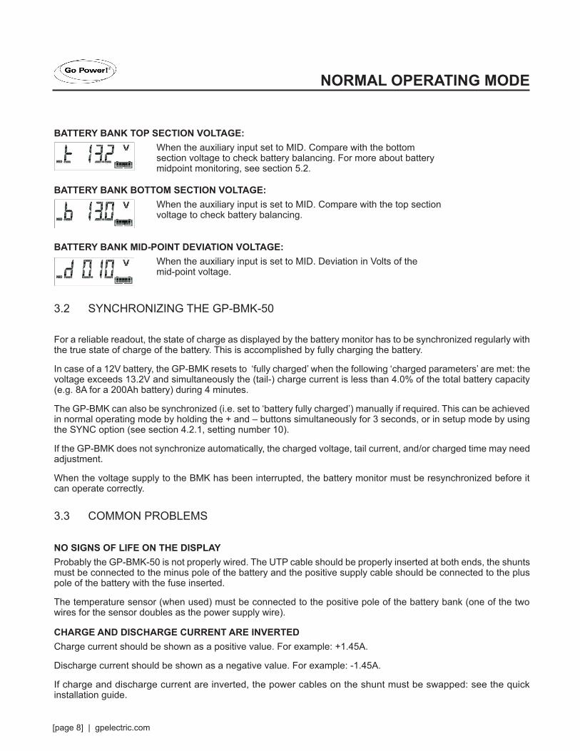
BATTERY BANK TOP SECTION VOLTAGE: When the auxiliary input set to MID. Compare with the bottom
section voltage to check battery balancing. For more about battery midpoint monitoring, see section 5.2.
BATTERY BANK BOTTOM SECTION VOLTAGE: When the auxiliary input is set to MID. Compare with the top section
voltage to check battery balancing.
BATTERY BANK MID-POINT DEVIATION VOLTAGE: When the auxiliary input is set to MID. Deviation in Volts of the
mid-point voltage.
3.2 SYNCHRONIZING THE GP-BMK-50
For a reliable readout, the state of charge as displayed by the battery monitor has to be synchronized regularly with the true state of charge of the battery. This is accomplished by fully charging the battery.
In case of a 12V battery, the GP-BMK resets to ‘fully charged’ when the following ‘charged parameters’ are met: the voltage exceeds 13.2V and simultaneously the (tail-) charge current is less than 4.0% of the total battery capacity (e.g. 8A for a 200Ah battery) during 4 minutes.
The GP-BMK can also be synchronized (i.e. set to ‘battery fully charged’) manually if required. This can be achieved in normal operating mode by holding the + and – buttons simultaneously for 3 seconds, or in setup mode by using the SYNC option (see section 4.2.1, setting number 10).
If the GP-BMK does not synchronize automatically, the charged voltage, tail current, and/or charged time may need adjustment.
When the voltage supply to the BMK has been interrupted, the battery monitor must be resynchronized before it can operate correctly.
3.3 COMMON PROBLEMS
NO SIGNS OF LIFE ON THE DISPLAYProbably the GP-BMK-50 is not properly wired. The UTP cable should be properly inserted at both ends, the shunts must be connected to the minus pole of the battery and the positive supply cable should be connected to the plus pole of the battery with the fuse inserted.
The temperature sensor (when used) must be connected to the positive pole of the battery bank (one of the two wires for the sensor doubles as the power supply wire).
CHARGE AND DISCHARGE CURRENT ARE INVERTEDCharge current should be shown as a positive value. For example: +1.45A.
Discharge current should be shown as a negative value. For example: -1.45A.
If charge and discharge current are inverted, the power cables on the shunt must be swapped: see the quick installation guide.

gpelectric.com | [page 9]
THE GP-BMK-50 DOES NOT SYNCHRONIZE AUTOMATICALLYOne possibility is that the battery never reaches the fully charged state. The other possibility is that the charged voltage setting should be lowered and/or the tail current setting should be increased. See section 4.2.1.
THE GP-BMK-50 SYNCHRONIZES TOO EARLYIn solar systems or other applications with fluctuating charge currents the charged voltage should be set only slightly below the absorption charge voltage (for example: 14.1V in case of 14.4V absorption voltage). This will prevent the GP-BMK-50 from switching prematurely to 100% state of charge.
SYNC AND BATTERY ICON ARE BLINKINGThis means the battery is not synchronized. Charge the batteries and the GP-BMK-50 should sync automatically. If that doesn’t work, review the sync settings, Or if you know the battery is fully charged but don’t want to wait until the GP-BMK-50 synchronizes, press and hold the UP and DOWN button simultaneously until you hear a beep. See section 4.2.1.
4.1 WHY SHOULD I MONITOR MY BATTERY?
Batteries are used in a wide variety of applications, mostly to store energy for later use. But how much energy is stored in the battery? No one can tell just by looking at it.
The service life of batteries depends on many factors. Battery life may be shortened by under-charging, over-charging, excessively deep discharges, excessive charge or discharge current and high ambient temperature. By monitoring the battery with an advanced battery monitor, important feedback is given to the user so that remedial measures can be taken when necessary. Doing this will extend battery liferesulting in the GP-BMK-50 quickly paying for itself.
4.2 HOW DOES THE GP-BMK-50 WORK?
The main function of the GP-BMK-50 is to follow and indicate the state of change of a battery, in particular to prevent unexpected total discharge.
The GP-BMK-50 continuously measures the current flow in and out of the battery. Integration of this current over time (which, if the current is a fixed amount of Amps, boils down to multiplying current and time) gives the net amount of Ah added or removed.
Example: discharge current of 10A during 2 hours will take 10 x 2 = 20Ah from the battery.
However, there are external components that negatively affect a battery capacities, such as rate of discharge, charge efficiency, and temperature.
4.2.1 BATTERY CAPACITY AND THE RATE OF DISCHARGE
The capacity of a battery is rated in ampere-hours (Ah). For example, a lead acid battery that can deliver a current of 5A during 20 hours is rated at C20 = 100Ah (5 x 20 = 100).
When the same 100Ah battery is discharged completely in two hours, it may only give C2 = 56AH (because the higher rate of discharge).
The GP-BMK-50 takes this phenomenon into account with Peukert’s formula. (See section 5.1).
4. FEATURES AND FUNCTIONALITY
[page 10] | gpelectric.com
4.2.2 CHARGE EFFICIENCY (CEF)
The charge efficiency of a lead acid battery is almost 100% as long as no gas generation takes place. Gassing means that part of the charge current is not transformed into chemical energy, which is stored in the plates of the battery, but is used to decompose water into oxygen and hydrogen gas (highly explosive!). The Amp-hours stored in the plates can be retrieved during the next discharge, whereas the Amp-hours used to decompose water are lost. Gassing can easily be observed in flooded batteries. Please note that the oxygen only end of charge phase of sealed (VRLA) gel and AGM batteries also results in a reduced charge efficiency.
A charge efficiency of 95% means that 10Ah must be transferred to the battery to get 9.5Ah actually stored in the battery. The charge efficiency of a battery depends on battery type, age and usage.
The GP-BMK-50 takes this phenomenon into account with the charge efficiency factor. (See section 4.2.2, setting number 06.
4.3 BATTERY STATE OF CHANGE DISPLAY OPTIONS
The GP-BMK-50 can display both the Amp-hours removed (consumed Amphours readout, compensated for charge efficiency only) and the actual state of charge in percent (state of charge readout, compensated for charge efficiency and Peukert efficiency). Reading the state of charge is the best way to monitor the battery.
The GP-BMK-50 also estimates how long the battery can support the present load, the time to go readout. This is the actual time left until the battery is discharged to the discharge floor. The factory setting is 50% (See 4.2.2, setting number 16).
If the loads are fluctuating heavily, it is best not to rely on this reading too much since it is a momentary readout and must be used as a guideline only. We always encourage the use of the state of change readout for accurate battery monitoring.
4.4 HISTORY DATA
The GP-BMK-50 stores events which can be used at a later date to evaluate usage patterns and battery health.
Select the history data menu by pressing ENTER when in normal mode (See section 4.3).
4.5 USE OF ALTERNATIVE SHUNTS
The GP-BMK-50 is supplied with a 500A/50mV shunt. For most applications, this should be suitable, however, the GP-BMK-50 can be configured to work with a wide range of different shunts. Shunts of up to 9999A and/or 75mV can be used.
When using a shunt other than the one supplied with the GP-BMK-50, please proceed as follows:
Unscrew the PCB from the supplied shunt.
Mount the PCB on the new shunt, ensuring that there is good electrical contact between the PCB and the shunt.
Connect the shunt and GP-BMK-50 as shown in the quick installation guide.
Follow the set-up wizard (Section 1.1 and 1.2).
gpelectric.com | [page 11]
After completion of the set-up wizard, set the proper shunt current and shunt voltage according to Section 4.2.5, setting number 65 and 66.
If the GP-BMK-50 reads a non-zero current, even when there is no load and the battery is not being charged, calibrate the zero current reading (see section 4.2.1, setting number 09).
4.6 AUTOMATIC DETECTION OF NOMINAL SYSTEM VOLTAGE
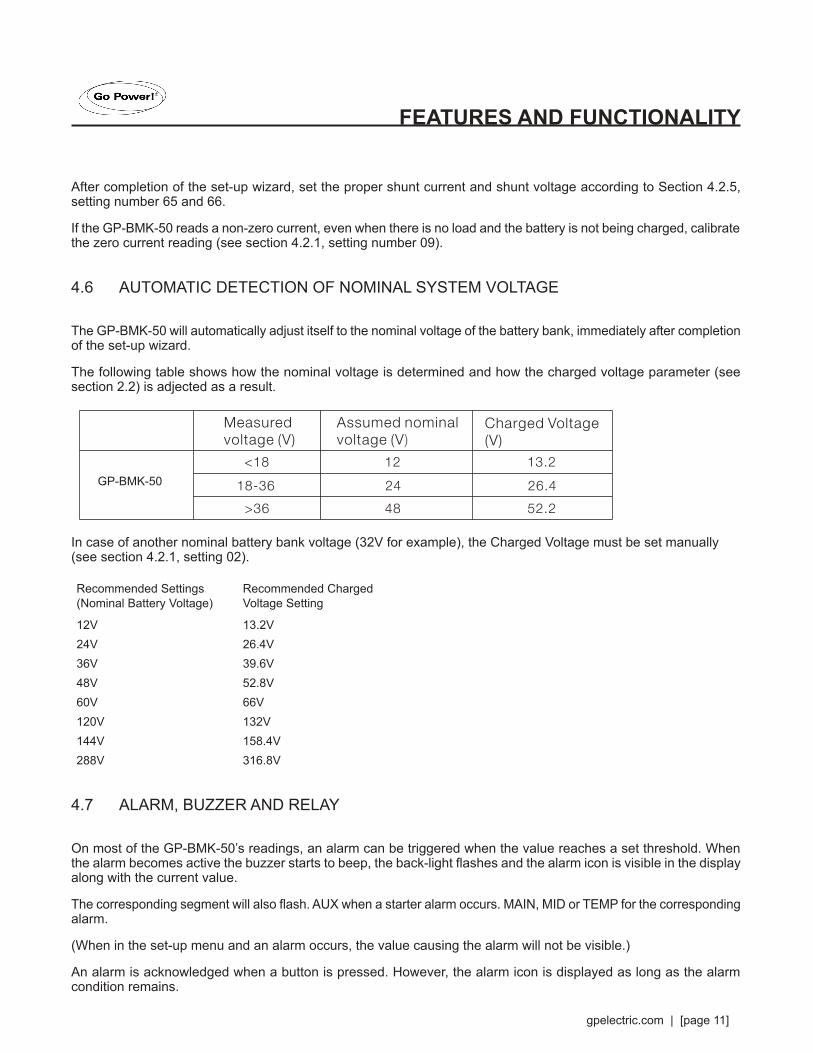
The GP-BMK-50 will automatically adjust itself to the nominal voltage of the battery bank, immediately after completion of the set-up wizard.
The following table shows how the nominal voltage is determined and how the charged voltage parameter (see section 2.2) is adjected as a result.
In case of another nominal battery bank voltage (32V for example), the Charged Voltage must be set manually (see section 4.2.1, setting 02).
Recommended Settings (Nominal Battery Voltage)
Recommended Charged Voltage Setting
12V 13.2V24V 26.4V36V 39.6V48V 52.8V60V 66V120V 132V144V 158.4V288V 316.8V
4.7 ALARM, BUZZER AND RELAY
On most of the GP-BMK-50’s readings, an alarm can be triggered when the value reaches a set threshold. When the alarm becomes active the buzzer starts to beep, the back-light flashes and the alarm icon is visible in the display along with the current value.
The corresponding segment will also flash. AUX when a starter alarm occurs. MAIN, MID or TEMP for the corresponding alarm.
(When in the set-up menu and an alarm occurs, the value causing the alarm will not be visible.)
An alarm is acknowledged when a button is pressed. However, the alarm icon is displayed as long as the alarm condition remains.
FEATURES AND FUNCTIONALITY
GP-BMKGP-BMK-50

[page 12] | gpelectric.com
It is also possible to trigger the relay when an alarm condition occurs.
The relay contact is open when the coil is de-energized (NO contact) and will close when the relay is energized.
Factory default setting: the relay is controlled by the state of charge of the battery bank. The relay will be energized when the state of charge decreases to less than 50% (the discharge floor) and will be de-energized when the battery has been recharged to 90% state of charge. See section 4.2.2. The relay function can be inverted: de-energized becomes energized and vice versa. See section 4.2.2.
When the relay is energized, the current drawn by the GP-BMK-50 will increase slightly (see technical data).
4.8 INTERFACE OPTIONS
4.8.1 CUSTOM INTEGRATION (PROGRAMMING REQUIRED)
The Bluetooth Dongle port can be used to read data and change settings. The Bluetooth Dongle protocol is simple to implement.
Transmitting data to the GP-BMK-50 is not necessary for simple applications, the GP-BMK-50 automatically sends all readings every second. All the details are explained in this document. Visit gpelectric.com/go-power-connect for more information
4.9 ADDITIONAL FUNCTIONALITY OF THE GP-BMK-50
In addition to the comprehensive monitoring of the main battery system, the GP-BMK-50 provides a second monitoring input. This secondary input has three configurable options, described below.
4.9.1 AUXILIARY BATTERY MONITORINGWiring diagram: see the quick installation guide. Fig 3
This configuration provides basic monitoring of a second battery, displaying its voltage. This is useful for systems with a separate starter battery.
4.9.2 BATTERY TEMPERATURE MONITORING
Wiring diagram: see the quick installation guide. Fig 4
This temperature sensor is not interchangeable with other temperature sensors, as provided with battery chargers. The temperature sensor must be connected to the positive pole of the battery bank (one of the two wires of the sensor doubles as the power supply wire). The temperature can be displayed in degrees Celsius or degrees Fahrenheit, see section 4.2.5, setting number 67.
The temperature measurement can also be used to adjust battery capacity to temperature, see section 4.2.5, setting number 68.
The available battery capacity decreases with temperature. Typically, the reduction, compared to the capacity at 20°C, is 18% at O°C and 40% at -20°C.
FEATURES AND FUNCTIONALITY
gpelectric.com | [page 13]
4.9.3 MIDPOINT VOLTAGE MONITORING
Wiring diagram: see the quick installation guide. Fig 5 - 12
One bad cell or one bad battery can destroy a large, expensive battery bank. A short circuit or high internal leakage current in one cell for example will result in under charge of that cell and over charge of the other cells.
Similarly, one bad battery in a 24Vor 48V bank of several series/parallel connected 12V batteries can destroy the whole bank.
Moreover, when cells or batteries are connected in series, they should all have the same initial state-of-charge. Small differences will be ironed out during absorption or equalize charging, but large differences will result in damage during charging due to excessive gassing of the cells or batteries with the highest initial state-of-charge.
A timely alarm can be generated by monitoring the midpoint of the battery bank. For more information, see section 5.1.
5.1 INITIAL STARTUPEvery BMK must go through this initial startup process. Note: this process cannot be performed by the Go Power Connect App.
If at any time an error is made during this process hold the “select” and “Setup” buttons at the same time for three seconds.
There are only two settings that need to be saved before using the unit. Battery Capacity (total amp hours of your battery bank) and auxiliary battery status.
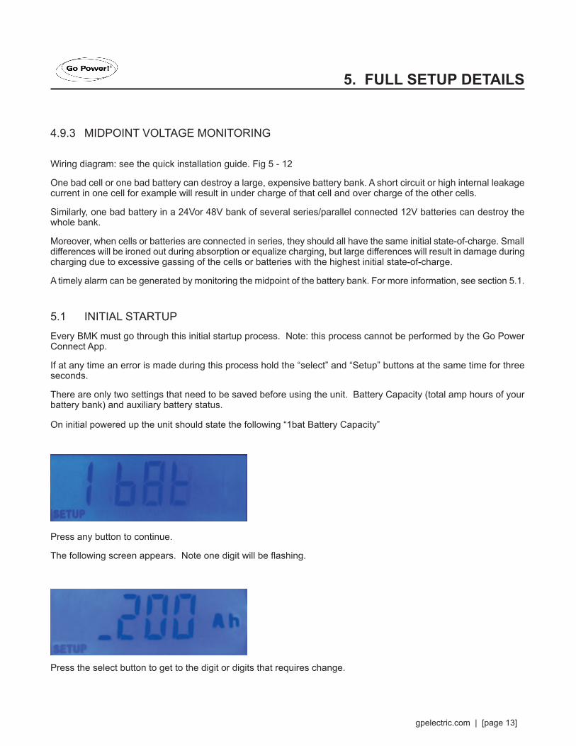
On initial powered up the unit should state the following “1bat Battery Capacity”
Press any button to continue.
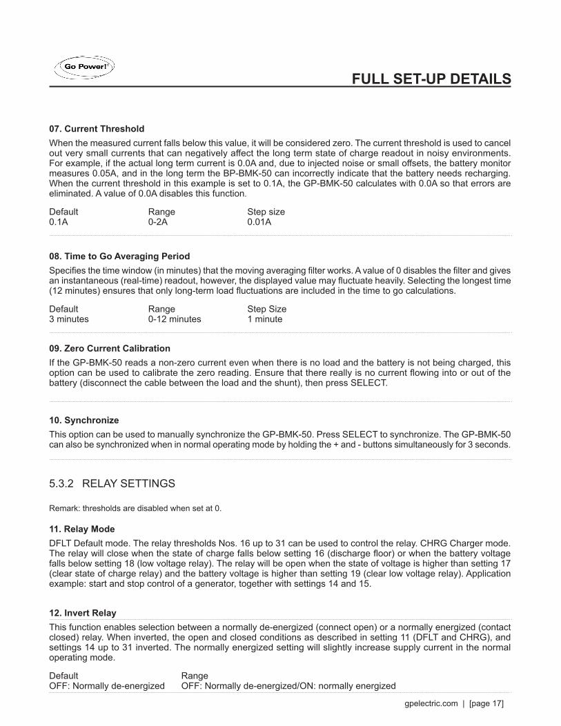
The following screen appears. Note one digit will be flashing.
Press the select button to get to the digit or digits that requires change.
5. FULL SETUP DETAILS

[page 14] | gpelectric.com
Once the correct digit is flashing, use the up and down arrow to select the correct value based on the battery bank total amp hour capacity. Once the value is set, press the select button until the cursor no longer is flashing.
Next press “Setup”
The following Menu appears. Press “Select”
You now will have three options, Starter Battery, (Start) “TEMP” (an optional temperature sensor (we do not have a temp sensor option but it has not been removed from firmware)) Mid-point Battery (In larger battery banks the user can get a battery voltage from the middle of the battery bank if required) check quick start guide for wiring diagram and explanation.
Default is starter battery, even if the battery is not connected.
Use the up and down arrows to select the option required, then press select to save the option.
Pressing setup will now bring the user to the main display screen.
Your BMK is now setup.
INITIAL STARTUP

gpelectric.com | [page 15]
5.2 USING THE MENUSFour buttons control the GP-BMK-50. The function of the buttons depends on which mode the GP-BMK-50 is in.
When power is applied for the first time or when factory settings have been restored, the GP-BMK-50 will start the set-up wizard (see section 2). Thereafter, if power is applied, the GP-BMK-50 will start in normal mode (see section 3).
5.3 FUNCTIONS OVERVIEW
The following summary describes all the parameters of the GP-BMK-50.
- Press SETUP for two seconds to access these functions and use the + and - buttons to browse them.
- Press SELECT to access the desired parameter.
- Use SELECT and the + an - buttons to customize. A short beep confirms the setting.
- Press SETUP at any time to return to the scrolling text and press again to return to normal mode.
FULL SET-UP DETAILS

[page 16] | gpelectric.com
5.3.1 BATTERY SETTINGS
01. Battery CapacityBattery capacity in Amp hours.Default Range Step size200Ah 1-9999Ah 1Ah
02. Charged VoltageThe battery voltage must be above this voltage level to consider the battery as fully charged. The charged-voltage-parameter should always be slightly below the end of charge voltage of the charger (usually 0.2V or 0.3V below the float voltage of the charger). See section 3.7 for recommended settings.
GP-BMK-50Default Range Step SizeSee table, sec 3.7 0-95V 0.1V
03. Tail CurrentOnce the charge current has dropped to less than the set tail current (expressed as percentage of the battery capacity), the battery is considered as fully charged.
Remark:Some battery chargers stop charging when the current drops below a set threshold. The tail current must be set higher than this threshold.
Default Range Step Size4% 0.5-10% 0.1%
04. Charged Detection TimeThis is the time the charged-parameters (Charged Voltage and Tail Current) must be met in order to consider the battery fully charged..
Default Range Step size3 minutes 1-50 minutes 1 minute
05. Peukert ExponentWhen unknown, it is recommended to keep this value at 1.25 for lead acid batteries and 1.05 Li-ion batteries. A value of 1.00 disables the Peukert compensation.
Default Range Step Size1.25 1-1.5 0.01
06. Charge Efficiency FactorThe Charge Efficiency Factor compensates for the Ah losses during charging. 100% means no loss.
Default Range Step Size95% 50-100% 1%
FULL SET-UP DETAILS
gpelectric.com | [page 17]
07. Current ThresholdWhen the measured current falls below this value, it will be considered zero. The current threshold is used to cancel out very small currents that can negatively affect the long term state of charge readout in noisy environments. For example, if the actual long term current is 0.0A and, due to injected noise or small offsets, the battery monitor measures 0.05A, and in the long term the BP-BMK-50 can incorrectly indicate that the battery needs recharging. When the current threshold in this example is set to 0.1A, the GP-BMK-50 calculates with 0.0A so that errors are eliminated. A value of 0.0A disables this function.
Default Range Step size0.1A 0-2A 0.01A
08. Time to Go Averaging PeriodSpecifies the time window (in minutes) that the moving averaging filter works. A value of 0 disables the filter and gives an instantaneous (real-time) readout, however, the displayed value may fluctuate heavily. Selecting the longest time (12 minutes) ensures that only long-term load fluctuations are included in the time to go calculations.
Default Range Step Size3 minutes 0-12 minutes 1 minute
09. Zero Current CalibrationIf the GP-BMK-50 reads a non-zero current even when there is no load and the battery is not being charged, this option can be used to calibrate the zero reading. Ensure that there really is no current flowing into or out of the battery (disconnect the cable between the load and the shunt), then press SELECT.
10. SynchronizeThis option can be used to manually synchronize the GP-BMK-50. Press SELECT to synchronize. The GP-BMK-50 can also be synchronized when in normal operating mode by holding the + and - buttons simultaneously for 3 seconds.
5.3.2 RELAY SETTINGS
Remark: thresholds are disabled when set at 0.
11. Relay ModeDFLT Default mode. The relay thresholds Nos. 16 up to 31 can be used to control the relay. CHRG Charger mode. The relay will close when the state of charge falls below setting 16 (discharge floor) or when the battery voltage falls below setting 18 (low voltage relay). The relay will be open when the state of voltage is higher than setting 17 (clear state of charge relay) and the battery voltage is higher than setting 19 (clear low voltage relay). Application example: start and stop control of a generator, together with settings 14 and 15.
12. Invert RelayThis function enables selection between a normally de-energized (connect open) or a normally energized (contact closed) relay. When inverted, the open and closed conditions as described in setting 11 (DFLT and CHRG), and settings 14 up to 31 inverted. The normally energized setting will slightly increase supply current in the normal operating mode.
Default Range OFF: Normally de-energized OFF: Normally de-energized/ON: normally energized
FULL SET-UP DETAILS

[page 18] | gpelectric.com
13. Relay State (Read Only)Displays whether the relay is open or closed (de-energized or energized).
Range OPEN/CLOSED
14. Relay Minimum Closed TimeSets the minimum amount of time that the CLOSED condition will remain present after the relay has been energized (changes to OPEN and de-energized if the relay function has been inverted). Application example: set a minimum generator run time (relay in CHRG mode).
15. Relay-off DelaySets the amount of time the de-energize relay condition must be present before the relay opens. Application example: keep a genereator running for a while to better charge the battery (relay in CHRG mode).
Default Range Step Size0 minutes 0-500 minutes 1 minute
16. SOC Relay (Discharge Floor)When the state-of-charge percentage has fallen below this value, the relay will close. The time-to-go displayed is the time to reach the discharge floor.
Default Range Step size50% 0-99% 1%
17. Clear SOC RelayWhen the state-of-charge percentage has risen above this value, the relay will open (after a delay, depending on setting 14 and/or 15). This value needs to be greater than the previous parameter setting. When the value is equal to the previous parameter the state-of-charge percentage will not close the relay.
Default Range Step Size90% 0-99% 1%
18. Low Voltage RelayWhen the battery voltage falls below this value for more than 10 seconds the relay will close.
19. Clear Low Voltage RelayWhen the battery voltage rises above this value, the relay will open (after a delay,depending on setting 14 and/or 15). This value needs to be greater than or equal to the previous parameter.
20. High Voltage RelayWhen the battery voltage rises above this value for more than 10 seconds the relay will close.
21. Clear High Voltage RelayWhen the battery voltage falls below this value, the relay will open (after a delay, depending on setting 14 and/or 15). This value needs to be less than or equal to the previous parameter.
FULL SET-UP DETAILS

gpelectric.com | [page 19]
GP-BMK-50Default Range Step Size0V 0-95V 0.1V
22. Low Starter Voltage RelayWhen the auxiliary (e.g. starter battery) voltage falls below this value for more than 10 seconds the relay will be activated.
23. Clear Low Starter Voltage RelayWhen the auxiliary voltage rises above this value, the relay will open (after a delay,depending on setting 14 and/or 15). This value needs to be greater than or equal to the previous parameter.
24. Higher Starter Voltage RelayWhen the auxiliary (e.g. starter battery) voltage rises above this value for more than 10 seconds, the relay will be activated.
25. Clear High Starter Voltage RelayWhen the auxiliary voltage falls below this value, the relay will open (after a delay, depending on setting 14 and/or 15). This value needs to be less than or equal to the previous parameter.
Default Range Step Size0V 0-95V 0.1V
26. High Temperature RelayWhen the battery temperature rises above this value for more than 10 seconds, the relay will be activated.
27. Clear High Temperature RelayWhen the temperature falls below this value, the relay will open (after a delay, depending on setting 14 and/or 15). This value needs to be less than or equal to the previous parameter.
28. Low Temperature RelayWhen the temperature falls below this value for more than 10 seconds, the relay will be activated.
29. Clear Low Temperature RelayWhen the temperature rises above this value, the relay will open (after a delay, depending on setting 14 and/or 15). This value needs to be greater than or equal to the previous parameter. See setting 67 for choosing between °C and °F.
Default Range Step Size0°C -99 - 99°C 1°C0°F -146 - 210°F 1°F
30. Mid Voltage RelayWhen the mid-point voltage deviation rises above this value for more than 10 seconds, the relay will be activated. See section 5.2 for more information about the mid-point voltage.
FULL SET-UP DETAILS

[page 20] | gpelectric.com
31. Clear Mid Temperature RelayWhen the mid-point voltage deviation falls below this value, the relay will open (after a delay, depending on setting 14 and/or 15). This value needs to be less than or equal to the previous parameter.
Default Range Step Size0% 0-99% 0.1%
5.3.3 ALARM BUZZER SETTINGS
Remark: thresholds are disabled when set at 0.
32. Alarm BuzzerWhen set, the buzzer will sound an alarm. After a button is pressed the buzzer will stop sounding. When disabled the buzzer will not sound an alarm.
Default RangeON ON/OFF
33. Low SOC AlarmWhen the state-of-charge falls below this value for more than 10 seconds the low SOC alarm is turned on. This is a visual and audible alarm. It does not energize the relay.
34. Clear Low SOC AlarmWhen the state-of-charge rises above this value, the alarm is turned off. This value needs to be greater than or equal to the previous parameter.
Default Range Step Size0% 0-99% 1%
35. Low Voltage AlarmWhen the battery voltage falls below this value for more than 10 seconds the low voltage alarm is turned on. This is a visual and audible alarm. It does not energize the relay.
36. Clear Low Voltage AlarmWhen the battery voltage rises above this value, the alarm is turned off. This value needs to be greater than or equal to the previous parameter.
37. Low Voltage AlarmWhen the battery voltage rises above this value for more than 10 seconds the, low voltage alarm is turned on. This is a visual and audible alarm. It does not energize the relay.
38. Clear High Voltage AlarmWhen the battery voltage falls below this value, the alarm is turned off. This value needs to be less than or equal to the previous parameter.
FULL SET-UP DETAILS

gpelectric.com | [page 21]
GP-BMK-50Default Range Step Size0V 0-95V 0.1V
39. Low Starter Voltage AlarmWhen the auxiliary (e.g. starter battery) voltage falls below this value for more than 10 seconds the alarm will be activated. This is a visual and audible alarm. It does not energize the relay.
40. Clear Low Starter Voltage AlarmWhen the auxiliary voltage rises above this value, the alarm is switched off. This value needs to be greater than or equal to the previous parameter.
41. High Starter Voltage AlarmWhen the auxiliary (e.g. starter battery) voltage rises above this value for more than 10 seconds, the alarm will be activated. This is a visual and audible alarm. It does not energize the relay.
42. Clear High Starter Voltage AlarmWhen the auxiliary voltage falls below this value, the alarm is switched off. This value needs to be less than or equal to the previous parameter.
Default Range Step SizeOV 0-95V 0.1 V
43. High Temperature AlarmWhen the battery temperature rises above this value for more than 10 seconds, the alarm will be activated. This is a visual and audible alarm. It does not energize the relay.
44. Clear High Temperature AlarmWhen the temperature falls below this value, the alarm is switched off. This value needs to be less than or equal to the previous parameter.
45. Low Temperature AlarmWhen the temperature falls below this value for more than 10 seconds, the alarm will be activated. This is a visual and audible alarm. It does not energize the relay.
46. Clear Low Temperature AlarmWhen the temperature rises above this value, the alarm is switched off. This value needs to be greater than or equal to the previous parameter. See parameter 67 for choosing between °C and °F.
Default Range Step Size0°C -99 - 99°C 1°C0°F -146 - 210°F 1°F
FULL SET-UP DETAILS

[page 22] | gpelectric.com
47. Mid Voltage AlarmWhen the mid-point voltage deviation rises above this value for more than 10 seconds, the alarm will be activated. This is a visual and audible alarm. It does not energize the relay. See section 5.2 for more information about midpoint voltage.
Default Range Step Size2% 0-99% 0.1%
48. Clear Mid Voltage AlarmWhen the mid-point voltage deviation falls below this value, the alarm is switched off. This value needs to be less than or equal to the previous parameter.
Default Range Step Size1.5% 0-99% 0.1%
5.3.4 DISPLAY SETTINGS
49. Black-light IntensityThe intensity of the back-light, ranging from 0 (always off) to 9 (maximum intensity).
Default Range Step Size5 0-9 1
50. Black-light Always OnWhen set the back-light will not automatically turn off after 60 seconds of inactivity.
Default Range OFF OFF/ON
51. Scroll SpeedThe scroll speed of the display, ranging from 1 (very slow) to 5 (very fast).
Default Range Step Size2 1-5 1
52. Main Voltage DisplayMust be ON to display the voltage of the main battery in the monitoring menu.
53. Current DisplayMust be ON to display current in the monitoring menu.
54. Power DisplayMust be ON to display power in the monitoring menu.
55. Consumed Ah DisplayMust be ON to display consumed Ah in the monitoring menu.
FULL SET-UP DETAILS

gpelectric.com | [page 23]
56. State of Charge DisplayMust be ON to display state-of-charge in the monitoring menu.
57. Time to Go DisplayMust be ON to display time-to-go in the monitoring menu.
58. Starter Voltage DisplayMust be ON to display the auxiliary voltage in the monitoring menu.
59. Temperature DisplayMust be ON to display the temperature in the monitoring menu.
60. Mid Voltage DisplayMust be ON to display the mid-point voltage in the monitoring menu.
Default Range OFF OFF/ON
5.3.5 MISCELLANEOUS
61. Software Version (Read Only)The software version of the GP-BMK-50.
62. Restore DefaultsResets all settings to factory default by pressing SELECT. When in normal operating mode, factory settings can be restored by pressing SETUP and SELECT simultaneously for 3 seconds (only if setting 64, Lock setup, is off).
63. Clear HistoryClears all history data by pressing SELECT.
64. Lock Set-UpWhen on, all settings (except this one) are locked and cannot be altered.
Default Range OFF OFF/ON
65. Shunt CurrentWhen using a shunt other than the one supplied with the BMK, set to the rated current of the shunt.
Default Range Step size500A 1-9999A 1A
66. Shunt VoltageWhen using a shunt other than the one supplied with the BMK, set to the rated voltage of the shunt.
FULL SET-UP DETAILS

[page 24] | gpelectric.com
Default Range Step size50mV 1mV-75mV 1mV
67. Temperature UnitCELC - Displays the temperature in °C.FAHR - Displays the temperature in °F.
Default Range CELC CELC/FAHR
68. Temperature CoefficientThis is the percentage the battery capacity changes with temperature when temperature decreases to less than 20°C (above 20°C the influence of temperature on capacity is relatively low and is not taken into account). The unit of this value is “%cap/°C” or percent capacity per degree Celsius. The typical value (below 20°C) is 1%cap/°C for lead acid batteries and 0.5%cap/°C for Lithium Iron Phosphate batteries.
Default Range Step size0%cap/°C 0-2%cap/°C 0.1%cap/°C
69. Aux InputSets the function of the auxiliary input:
START - Auxiliary voltage, e.g. a starter battery.
MID - Mid-point voltage.
TEMP - Battery temperature.
70. Shunt VoltageWhen using a shunt other than the one supplied with the BMK, set to the rated voltage of the shunt.
Default Range Step size50mV 1mV-75mV 1mV
5.4 HISTORY DATA
The GP-BMK-50 tracks several parameters regarding the state of the battery which can be used to evaluate usage patterns and battery health.
Enter history data by pressing the SELECT button when in normal mode.
Press + or - to browse the various parameters.
Press SELECT again to stop scrolling and show the value.
Press + or - to browse the various values.
Press SELECT again to leave the historical menu and go back to normal operation mode.
The history data is stored in non-volatile memory and will not be lost when the power supply to the GP-BMK-50 is interrupted.
FULL SET-UP DETAILS
gpelectric.com | [page 25]
6.1 PEUKERT’S FORMULA: BATTERY CAPACITY & DISCHARGE RATE
The value which can be adjusted in Peukert’s formula is the exponent n: see the formula below.
In the GP-BMK-50, Peukert’s exponent can be adjusted from 1.00 to 1.50. The higher the Peukert exponent the faster the effective capacity ‘shrinks’ with increasing discharge rate. An ideal (theoretical) battery has a Peukert Exponent of 1.00 and has a fixed capacity; regardless of the size of the discharge current. The default setting for the Peukert exponent is 1.25. This is an acceptable average value for most lead acid batteries. Peukert’s equation is stated below:
log t2 - log t1 Cp = 1n · t where Peukert’s exponent n = log I1 - log I2
The battery specifications needed for calculation of the Peukert exponent are the rated battery capacity (usually the 20 h discharge rate 2) and for example a 5h discharge rate 2. See below for an example of how to calculate the Peukert exponent using these two specifications.
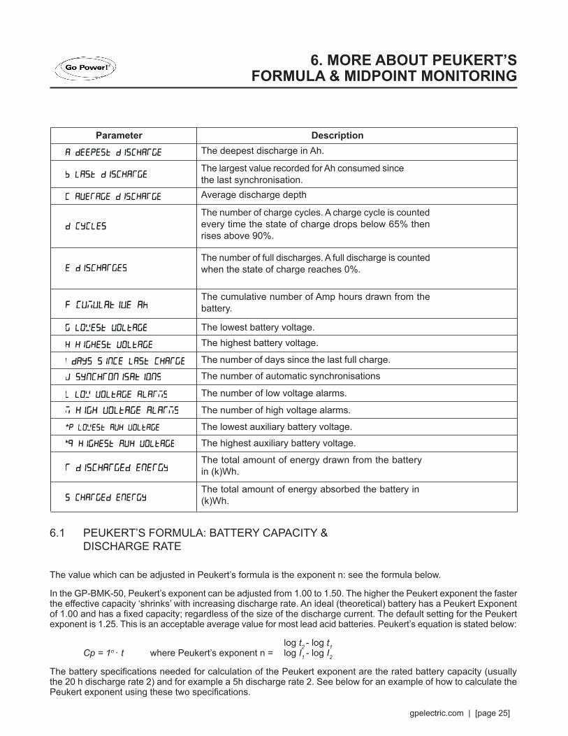
Parameter DescriptionThe deepest discharge in Ah.
The lowest battery voltage.The highest battery voltage.
The number of days since the last full charge.
The number of automatic synchronisations
The number of low voltage alarms.
The number of high voltage alarms.
The lowest auxiliary battery voltage.
The highest auxiliary battery voltage.
Average discharge depth
The largest value recorded for Ah consumed since the last synchronisation.
The number of charge cycles. A charge cycle is counted every time the state of charge drops below 65% then rises above 90%.
The number of full discharges. A full discharge is counted when the state of charge reaches 0%.
The total amount of energy drawn from the battery in (k)Wh.
The total amount of energy absorbed the battery in (k)Wh.
The cumulative number of Amp hours drawn from the battery.
6. MORE ABOUT PEUKERT’S FORMULA & MIDPOINT MONITORING
[page 26] | gpelectric.com
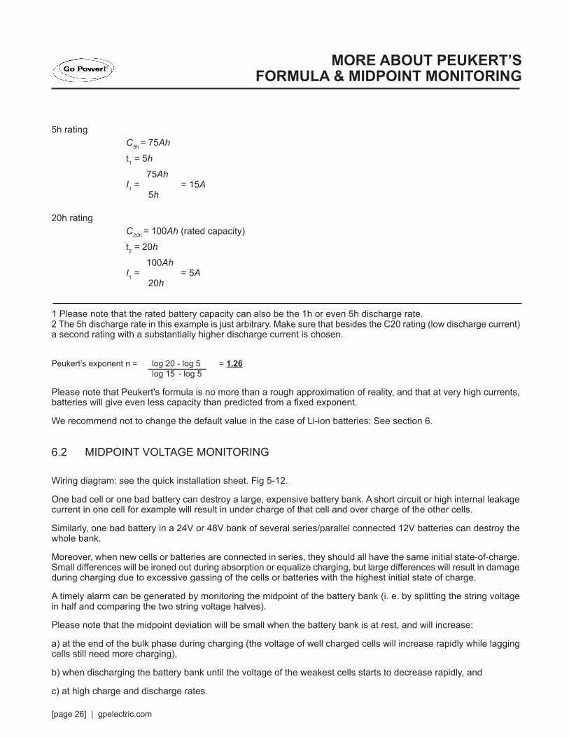
5h ratingC5h = 75Ah
t1 = 5h
75AhI1 = = 15A
5h
20h ratingC20h = 100Ah (rated capacity)t2 = 20h
100AhI1 = = 5A
20h
1 Please note that the rated battery capacity can also be the 1h or even 5h discharge rate.2 The 5h discharge rate in this example is just arbitrary. Make sure that besides the C20 rating (low discharge current) a second rating with a substantially higher discharge current is chosen.
Peukert’s exponent n = log 20 - log 5 = 1.26 log 15 - log 5
Please note that Peukert's formula is no more than a rough approximation of reality, and that at very high currents, batteries will give even less capacity than predicted from a fixed exponent.
We recommend not to change the default value in the case of Li-ion batteries: See section 6.
6.2 MIDPOINT VOLTAGE MONITORING
Wiring diagram: see the quick installation sheet. Fig 5-12.
One bad cell or one bad battery can destroy a large, expensive battery bank. A short circuit or high internal leakage current in one cell for example will result in under charge of that cell and over charge of the other cells.
Similarly, one bad battery in a 24V or 48V bank of several series/parallel connected 12V batteries can destroy the whole bank.
Moreover, when new cells or batteries are connected in series, they should all have the same initial state-of-charge. Small differences will be ironed out during absorption or equalize charging, but large differences will result in damage during charging due to excessive gassing of the cells or batteries with the highest initial state of charge.
A timely alarm can be generated by monitoring the midpoint of the battery bank (i. e. by splitting the string voltage in half and comparing the two string voltage halves).
Please note that the midpoint deviation will be small when the battery bank is at rest, and will increase:
a) at the end of the bulk phase during charging (the voltage of well charged cells will increase rapidly while lagging cells still need more charging),
b) when discharging the battery bank until the voltage of the weakest cells starts to decrease rapidly, and
c) at high charge and discharge rates.
MORE ABOUT PEUKERT’S FORMULA & MIDPOINT MONITORING

gpelectric.com | [page 27]
6.2.1 HOW THE % MIDPOINT DEVIATION IS CALCULATED
d (%) = 100*(Vt - Vb)/V
where:
d is the deviation in %
Vt is the top string voltage
Vb is the bottom string voltage
V is the voltage of the battery (V = Vt + Vb)
6.2.2 SETTING THE ALARM LEVEL
In case of VRLA (gel or AGM) batteries, gassing due to overcharging will dry out the electrolyte, increasing internal resistance and ultimately resulting in irreversible damage. Flat plate VRLA batteries start to lose water when the charge voltage approaches 15V (12V battery).
Including a safety margin, the midpoint deviation should therefore remain below 2% during charging.
When, for example, charging a 24V battery bank at 28,8V absorption voltage, a midpoint deviation of 2% would result in:
Vt = V*d/l 00* + Vb = V*d/l 00 + V - Vt
Therefore:
Vt = (V*(1 +d/l 00) / 2 = 28,8*1 ,02/2'" 14,7V
And:
Vb = (V*(I-d/l 00) / 2 = 28,8*0,98/2 '" 14,1 V
Obviously, a midpoint deviation of more than 2% will result in overcharging the top battery and undercharging the bottom battery. Two good reasons to set the midpoint alarm level at not more than d = 2%.
This same percentage can be applied to a 12V battery bank with a 6V midpoint. In case of a 48V battery bank consisting of 12V series connected batteries, the % influence of one battery on the midpoint is reduced by half. The midpoint alarm level can therefore be set at a lower level.
6.2.3 ALARM DELAY
In order to prevent the occurrence of alarms due to short term deviations that will not damage a battery, the deviation must exceed the set value during 5 minutes before the alarm is triggered.
A deviation exceeding the set value by a factor of two or more will trigger the alarm after 10 seconds.
MORE ABOUT PEUKERT’S FORMULA & MIDPOINT MONITORING

[page 28] | gpelectric.com
6.2.4 WHAT TO DO IN CASE OF AN ALARM DURING CHARGING
In case of a new battery bank the alarm is probably due to differences in initial state-of-charge. If deviation increases to more than 3%: stop charging and charge the individual batteries or cells separately first, or reduce charge current substantially and allow the batteries to equalize over time.
If the problem persists after several charge-discharge cycles:
a) In case of series-parallel connection disconnect the midpoint parallel connection wiring and measure the individual midpoint voltages during absorption charging to isolate batteries or cells which need additional charging.
b) Charge and then test all batteries or cells individually.
In case of an older battery bank which has performed well in the past, the problem may be due to:
a) Systematic under charge, more frequent charging or equalization charge needed (flooded deep cycle flat plate or OPzS batteries). Better and regular charging will solve the problem.
b) One or more faulty cells: proceed as suggested under a) or b).
6.2.5 WHAT TO DO IN CASE OF AN ALARM DURING DISCHARGING
The individual batteries or cells of a battery bank are not identical, and when fully discharging a battery bank the voltage of some cells will start dropping earlier than others. The midpoint alarm will therefore nearly always trip at the end of a deep discharge.
If the midpoint alarm trips much earlier (and does not trip during charging), some batteries or cells may have lost capacity or may have developed a higher internal resistance than others. The battery bank may have reached the end of service life, or one of more cells or batteries have developed a fault:
a) In case of series-parallel connection, disconnect the midpoint parallel connection wiring and measure the individual midpoint voltages during discharging to isolate faulty batteries or cells.
b) Charge and then test all batteries or cells individually.
MORE ABOUT PEUKERT’S FORMULA & MIDPOINT MONITORING

gpelectric.com | [page 29]
LiFeP04 is the most commonly used Li-ion battery chemistry. The factory default 'charged parameters' are in general also applicable to LiFeP04 batteries.
Some battery chargers stop charging when the current drops below a set threshold. The tail current must be set higher than this threshold.
The charge efficiency of Li-ion batteries is much higher than of lead acid batteries: We recommend to set the charge efficiency at 99%.
When subjected to high discharge rates, LiFeP04 batteries perform much better than lead-acid batteries. Unless the battery supplier advises otherwise, we recommend setting Peukert's exponent at 1.05.
IMPORTANT WARNINGLi-ion batteries are expensive and can be irreparably damaged due to over discharge or over charge.
Damage due to over discharge can occur if small loads (such as: alarm systems, relays, standby current of certain loads, back current drain of battery chargers or charge regulators) slowly discharge the battery when the system is not in use.
In case of any doubt about possible residual current draw, isolate the battery by opening the battery switch, pulling the battery fuse(s) or disconnecting the battery positive when the system is not in use.
A residual discharge current is especially dangerous if the system has been discharged completely and a low cell voltage shut down has occurred. After shutdown due to low cell voltage, a capacity reserve of approximately 1Ah per 100Ah battery capacity is left in a Li-ion battery. The battery will be damaged if the remaining capacity reserve is drawn from the battery. A residual current of 4mA for example may damage a 100Ah battery if the system is left in discharged state during more than 10 days (4mAx24h x 10 days = 0,96Ah).
The GP-BMK-50 draws 4mA from a 12V battery. The positive supply must therefore be interrupted If a system with Li-ion batteries is left unattended during a period long enough for the current draw by the GP-BMK-50 to completely discharge the battery.
7. LITHIUM IRON PHOSPHATE BATTERIES (LIFEPO4)
7. LITHIUM IRON PHOSPHATE BATTERIES (LIFEPO4)

[page 30] | gpelectric.com
Overview of the GP-BMK-50 display.
A: The value of the selected item is displayed with these digitsB: ColonC: Decimal separatorD: Main battery voltage iconE: Battery temperature iconF: Auxiliary voltage iconG: Mid-point voltage iconH: Set-up menu activeI: History menu activeJ: Battery needs to recharged (solid) or GP-BMK-50 is not synchronized (blinking together with K)K: Battery state of charge indicator (blinks when not synchronized)L: Unit of the selected item (e.g. W, kW, kWh, h, V, %, A, Ah, °C, °F)M: Alarm indicator
ScrollingThe GP-BMK-50 features a scrolling mechanism for long texts. The scroll speed can be changed by modifying the setting scroll speed in the settings menu. See section 4.2.4, parameter 51.
8. DISPLAY

gpelectric.com | [page 31]
GP-BMK
9. TECHNICAL DATA

[page 32] | gpelectric.com
With the Go Power! Bluetooth Dongle you can pair your phone to the Go Power! Connect app to receive live status info, see historical values from your GP-BMK and configure Go Power! products. Get live updates from your RV remotely using the Go Power! app for Android and iOS devices. Add the Bluetooth Dongle (GP-BTD) for even more flexibility, and connect to your BMK using Bluetooth technology.
Compatible Go Power! ProductsThe dongle can be connected to a variety of Go Power! products that feature the built-in direct port. For a full list of products please visit our website gpelectric.com for the most up-to-date information.
BLUETOOTH DONGLE

gpelectric.com | [page 33]
BATTERY MONITOR TEMPLATE

[page 34] | gpelectric.com
© 2018 Go Power!®
Worldwide Technical Support and Product Information gpelectric.com
Go Power! Headquarters201-710 Redbrick St, Victoria, BC Canada V8T 5J3
MAN_GP-BMK-50_RevA.7