Embed Size (px)
Citation preview
Distribution A – Approved for public release
Battery Management System (BMS)Design for Lithium-ion Batteries,
A Holistic Approach
holistic, adjective, \hō-ˈlis-tik\Merriam-Webster Dictionary: relating to or concerned with wholes or with complete systems rather than with the analysis of, treatment of,
or dissection into parts
Tom HoegerAdvanced Power & Energy Group, NSWC-Carderock
Code 636 Contractor: Spectrum Technology Group, Inc.
1
Distribution A – Approved for public release
DISCLAIMER AND LIMITATION
• This presentation is based on numerous years of experience in commercial, aerospace and governmental support designing, constructing, and trouble-shooting battery systems for Navy, Aerospace and Commercial Systems and represents the authors understanding of best, preferred and recommended practices, in the authors technical opinion.
• All images used in the presentation are taken from numerous open literature sources (web-access), are used for education and illustration purposes. Use of an image, diagram or manufacturer's product does not represent endorsement of, or negative opinion of, any design, configuration or manufacturer image presented.
• The material contained in this presentation does not represent any official change to Navy Policy, or Navy direction for lithium battery system designs, their test and diagnostics.
• Nothing in this presentation shall be construed or interpreted as official contractual direction or any requirement to make constructive change to deliverables or tasking for current or planned contracts. Only the authorized contracting official for your contract may authorize changes.
2
Distribution A – Approved for public release
Agenda
• Introduction• Definitions• What is a Battery Management System• Requirements• Design Process• Verification• Observations & Lessons Learned• Conclusion
3
Distribution A – Approved for public release
Introduction
• Due to the benefits of higher specific energy (Wh/kg), energy density (Wh/L) and specific power (W/kg), there has been a vast proliferation in the use of lithium-ion secondary batteries across all industries – consumer, industrial, medical and military/aerospace & defense
• With the improvements in power and energy come safety issues not usually observed with many prior mainstream secondary battery technologies
– Prior technologies were aqueous based electrolytes which do not burn– Organics found in Li+ batteries burn– Therefore while fire, smoke and the rare case of spontaneous disassembly were
observed in these prior tech’s (PbAc, NiCd, AgZn, NiMH, etc.) the effects are greater with Li+ batteries
• While significant, important work is being performed to identify inherently safer cells, lithium-ion secondary batteries are already here and in widespread use
• The purpose of this presentation is to provide the battery designer and procuring agent with the knowledge necessary to arrive at a safe and cost effective lithium-ion battery solution that meets its intended requirements
4
Distribution A – Approved for public release
What’s the Problem?
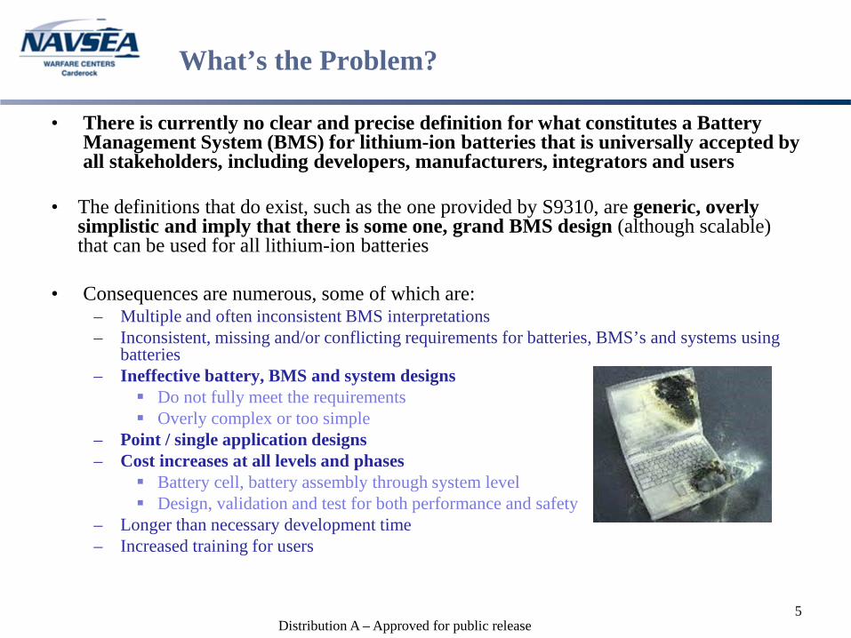
• There is currently no clear and precise definition for what constitutes a Battery Management System (BMS) for lithium-ion batteries that is universally accepted by all stakeholders, including developers, manufacturers, integrators and users
• The definitions that do exist, such as the one provided by S9310, are generic, overly simplistic and imply that there is some one, grand BMS design (although scalable) that can be used for all lithium-ion batteries
• Consequences are numerous, some of which are:– Multiple and often inconsistent BMS interpretations– Inconsistent, missing and/or conflicting requirements for batteries, BMS’s and systems using
batteries– Ineffective battery, BMS and system designs
Do not fully meet the requirements Overly complex or too simple
– Point / single application designs– Cost increases at all levels and phases
Battery cell, battery assembly through system level Design, validation and test for both performance and safety
– Longer than necessary development time– Increased training for users
5
Distribution A – Approved for public release
Terms and Definitions
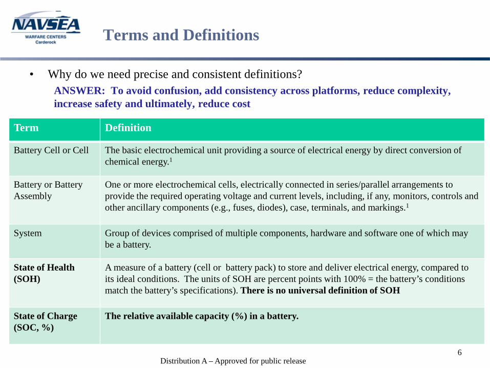
• Why do we need precise and consistent definitions?ANSWER: To avoid confusion, add consistency across platforms, reduce complexity, increase safety and ultimately, reduce cost
6
Term Definition
Battery Cell or Cell The basic electrochemical unit providing a source of electrical energy by direct conversion of chemical energy.1
Battery or Battery Assembly
One or more electrochemical cells, electrically connected in series/parallel arrangements to provide the required operating voltage and current levels, including, if any, monitors, controls and other ancillary components (e.g., fuses, diodes), case, terminals, and markings.1
System Group of devices comprised of multiple components, hardware and software one of which may be a battery.
State of Health (SOH)
A measure of a battery (cell or battery pack) to store and deliver electrical energy, compared to its ideal conditions. The units of SOH are percent points with 100% = the battery’s conditions match the battery’s specifications). There is no universal definition of SOH
State of Charge (SOC, %)
The relative available capacity (%) in a battery.

Distribution A – Approved for public release
NAVY Definition of Battery Management System
• NAVSEA S9310-AQ-SAF-010, Navy Lithium Battery Safety Program Responsibilities and Procedures
– Appendix A-1, Definitions. Battery Management System (BMS) – An electronic system designed for a secondary (rechargeable) battery that monitors the charging cycle to protect the individual cells of a battery from overcharging. A BMS may also be used to control/monitor discharge of individual cells in either a primary (non-rechargeable) or secondary (rechargeable) battery. Also known as Battery Monitoring Systems.
– 4-4.4 BATTERY MANAGEMENT SYSTEM (BMS). Large form rechargeable batteries must use a battery management system that provides access to information on the performance, cycle-count, age, and condition of the battery. This BMS may be integral to the battery and include the protections of paragraph 4-4.2 and 4-4.3 above, or the BMS may be an interface to the system the battery is installed in. These guidelines are also recommended for smaller batteries.
– 4-4.2 CELL-TO-CELL BALANCING MECHANISMS. During charging, differences in individual cells may lead to differing voltages in cell groups. Some cells may be undercharged, with a result of decrease in the overall battery capacity. Conversely, some cells may be overcharged, with the result of cell damage, shortening of life cycle, or the creation of safety issues. In order to achieve a uniform state of charge, consideration shall be given to including a cell-to-cell balancing mechanisms for use during battery charging systems.
– 4.4.3 OVERVOLTAGE PROTECTION. Rechargeable batteries shall have integrated overvoltage (over-charge) protection. These protections must disconnect the battery from the charging source. Disconnect must be automatic and not require operator action.
7
Distribution A – Approved for public release
BMS - Benefits of a Clear Definition
• Reduced nonrecurring cost, those associated with the design and validation of batteries and battery systems
• Reduced battery and system development time• Standardize interfaces to promote cross compatibility of batteries and
equipment expected to reduce recurring costs through– Increased production of fewer types of batteries– “Black box” designs fostering competition between multiple suppliers
• Reduce burden on users• INCREASED SAFETY!!!
– Identification of appropriate safety concerns/features– Elimination of failure modes introduced by unnecessary features
• In order to truly realize these benefits one must understand and define the functions and components of a BMS– Functions are what it needs to do– Components are the physical or tangible parts and pieces– A specific function may require multiple components – Similarly, a single component may be capable of performing multiple functions
8
Distribution A – Approved for public release
What are the Functions of a BMS
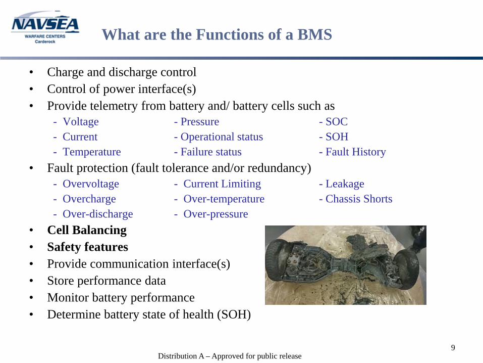
• Charge and discharge control• Control of power interface(s)• Provide telemetry from battery and/ battery cells such as
- Voltage - Pressure - SOC- Current - Operational status - SOH- Temperature - Failure status - Fault History
• Fault protection (fault tolerance and/or redundancy)- Overvoltage - Current Limiting - Leakage- Overcharge - Over-temperature - Chassis Shorts- Over-discharge - Over-pressure
• Cell Balancing• Safety features• Provide communication interface(s)• Store performance data• Monitor battery performance• Determine battery state of health (SOH)
9
Distribution A – Approved for public release
What Components Might Comprise a BMS
• The components comprising a BMS are determined largely by the battery capacity and required functions.
– Comprehensive system design is absolutely critical for large batteries and complex point designs
– Safety considerations generally become more of a factor as the size of a battery increases in terms of capacity and output voltage
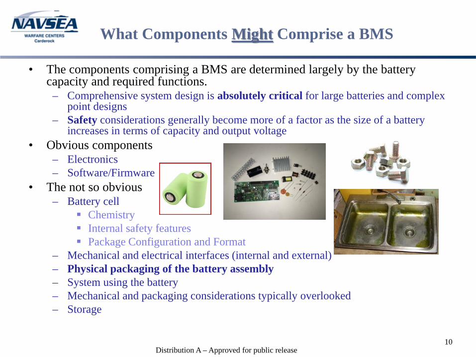
• Obvious components– Electronics– Software/Firmware
• The not so obvious– Battery cell
Chemistry Internal safety features Package Configuration and Format
– Mechanical and electrical interfaces (internal and external)– Physical packaging of the battery assembly– System using the battery– Mechanical and packaging considerations typically overlooked– Storage
10
Distribution A – Approved for public release
Requirements! Requirements! Requirements!
• Where does the design process start?Answer: With the requirements of course!
• Requirements are the vehicle through which specifications are communicated• The responsibility for establishing and maintaining requirements belongs primarily
to the “procuring agent” and not the “producer” (i.e. top → down)• Requirements should be comprehensive, reasonable, realistic, clear and precise to
assure arriving at a useable, cost effective product in a reasonable period of time• Requirements Flow
– The top → down flow of requirements should be maintained to the greatest extent possible.– There will almost always be some bottom → up flow of requirements, particularly during early
phases of development When these instances arise, they should be brought to the attention of the necessary upper
level agent(s) for adjudication as quickly as possible Implementation of these requirements should only occur after agreement has been reached
with the appropriate upper level agent(s)– Failure to adhere to these simple rules of thumb often leads to unnecessary and unplanned
redesign which in turn increases cost and schedule • Requirements must be verifiable by at least one (preferably two or more) of the
following methods:– Analysis– Inspection– Test
11
If a requirement can’t be verified it doesn’t belong!!!
Distribution A – Approved for public release
Things to Remember Regarding Requirements
• All requirements are NOT created equal!– Establishing a hierarchy of the requirements can be very beneficial.– Recommended ranking criteria for requirements.
Safety Performance (ex. capacity, voltage range, etc.) Cost Bells & Whistles
• Not all functions are necessary or required (ex. cell balancing)• Most requirements can be met through multiple implementations. When
multiple options exist, determine which makes the most sense based on cost, safety, reliability, maintenance, manufacturing, etc.
• Not all requirements need to be achieved within the battery.– Battery charger– Cell balancing circuitry
• “Better is the enemy of good enough!” - attributed to Voltaire“Learn it. Know it. Live it!” - Fast Times at Ridgemont High
12
Distribution A – Approved for public release
Requirements Wheel
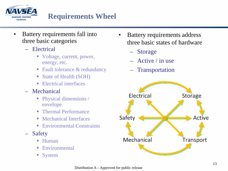
• Battery requirements fall into three basic categories– Electrical
Voltage, current, power, energy, etc.
Fault tolerance & redundancy State of Health (SOH) Electrical interfaces
– Mechanical Physical dimensions /
envelope Thermal Performance Mechanical Interfaces Environmental Constraints
– Safety Human Environmental System
• Battery requirements address three basic states of hardware– Storage– Active / in use– Transportation
13
Distribution A – Approved for public release
BMS Design Considerations
• Identify the functions required of the BMS requirements – Safety– Performance– Cost (recurring, nonrecurring, maintenance, repair, etc.)
• Identify failure modes at cell and battery assembly levels.• Determine level(s) at which these functions or features can or will be
implemented (cell, battery assembly or system)• Define interface requirements
– Electrical– Mechanical / Thermal
• Determine whether standard battery formats (18650, prismatic, pouch, etc.) are viable or whether a custom approach is necessary
• Generate a requirements matrix and reference it early and often, aggressively and track changes!
• Recognize up front that this will be an iterative process!– 1080 Design Process, expect at least 3 iterations– Hold peer reviews early, starting at the conceptual phase– Reassess continually but not to the point of paralysis
14
Distribution A – Approved for public release
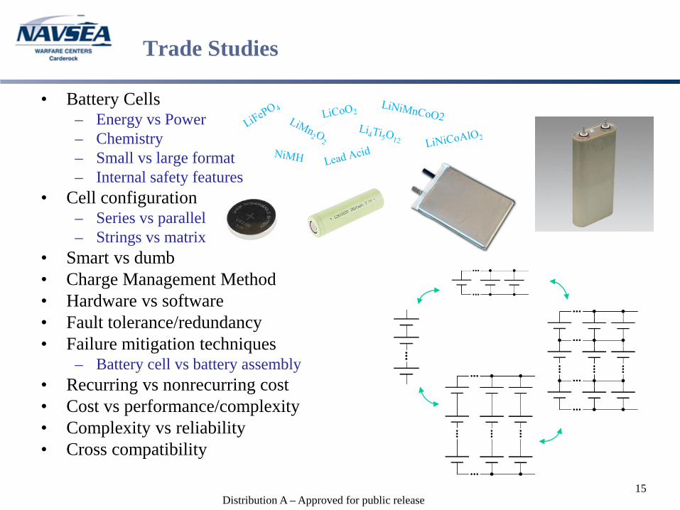
Trade Studies
• Battery Cells– Energy vs Power– Chemistry– Small vs large format– Internal safety features
• Cell configuration– Series vs parallel– Strings vs matrix
• Smart vs dumb• Charge Management Method• Hardware vs software• Fault tolerance/redundancy• Failure mitigation techniques
– Battery cell vs battery assembly• Recurring vs nonrecurring cost• Cost vs performance/complexity• Complexity vs reliability• Cross compatibility
15
Distribution A – Approved for public release
Design Verification
• Analysis– Electrical Worst Case Analysis (circuit performance)– Electrical, Electronic and Electro-mechanical Parts Stress Analysis– Fault Tree Analysis (FTA)– Failure Mode Effects and Criticality Analysis (FMECA)– Thermal Analysis– Mechanical Stress Analysis– Software verification
• Inspection– Parts– Workmanship– Processes
• Test– Electrical Performance– Mechanical & Environmental Performance– Safety– Software
16
Distribution A – Approved for public release
Lessons Learned & Observations - Requirements
• Existing standards do not adequately define safety requirements for batteries
• Specifications written stipulating implementations, goals and/or “desirements” instead of hard & fast requirements
• Loopholes and conflicting requirements in existing standards• Requirements not adequately developed by users / lack of adequate systems
engineering• Excessive supplier driven requirements (bottom → up instead of top →
down flow)• Beware calls for “graceful degradation”
– The gradual decrease in battery capacity over life and cycling is and example of graceful degradation
– The ability of a battery or system to continue to operate after suffering a failure is an example of fault tolerance
17
Distribution A – Approved for public release
Lessons Learned & Observations - Design
• Understanding failure modes and hazards of all components is essential to producing a safe battery design
• Lack of systems engineering • Trade studies lack quality or are missing all together (lacking objectivity)• Inadequate design/peer review
– Improper or missing skill sets– Insufficient experience– Reviews held too late in design process
• All too often a design starts with a specific component, particularly a specific battery cell (solution looking for a problem)
• Overly complex designs leading to poor/reduced reliability and single use designs
• Poor implementation of modularization• Design for test (hardware and software)!!!
18
Distribution A – Approved for public release
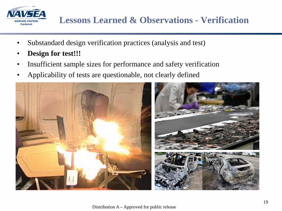
Lessons Learned & Observations - Verification
• Substandard design verification practices (analysis and test)• Design for test!!!• Insufficient sample sizes for performance and safety verification• Applicability of tests are questionable, not clearly defined
19
Distribution A – Approved for public release
Conclusion
• A BMS is NOT simply a set of electronics used to maintain battery state of charge and/or monitor state of health and subscribing to that view can lead to ineffective battery designs which do not meet requirements or cost goals and are application specific
• A BMS is the system of components, functions and features necessary to meet the performance, environmental and safety requirements of the battery and the system within which it is being used over the expected life of the product
• The scope, breadth and complexity of the BMS should be directly dependent upon the necessary battery requirements and not on “extra” features
• The BMS can permeate all levels of the battery and system using it, (e.g., battery cells, electronics, software, mechanical design) as well as have external components (e.g., storage, chargers) and therefore it is imperative that thorough system engineering is performed
• There is no “one size fits all” BMS20
Distribution A – Approved for public release
References
1. Linden’s Handbook of Batteries, 4th edition, Reddy, McGraw Hill, 20102. Meriam-Webster Dictionary, 1/2/20173. AD-A278 508, Failure Mode Effects and Criticality Analysis, Reliability
Analysis Center, 1993.4. MIL-STD-756B, Reliability Modeling and Prediction, 19815. MIL-STD-721C, Definitions of Terms for Reliability and Maintainability,
19816. MIL-HDBK-217F, Reliability Prediction of Electronic Equipment, 1991
Images1. batteryuniversity.com2. guide.alibaba.com3. wsj.com4. insideEEVs.com5. cnet.com6. crafthub.com
21
Distribution A – Approved for public release
Backup Slides
22
Distribution A – Approved for public release
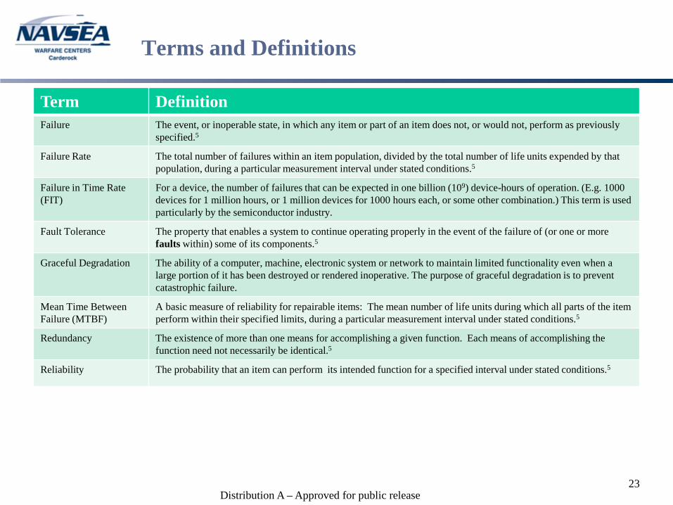
Terms and Definitions
Term DefinitionFailure The event, or inoperable state, in which any item or part of an item does not, or would not, perform as previously
specified.5
Failure Rate The total number of failures within an item population, divided by the total number of life units expended by that population, during a particular measurement interval under stated conditions.5
Failure in Time Rate (FIT)
For a device, the number of failures that can be expected in one billion (109) device-hours of operation. (E.g. 1000 devices for 1 million hours, or 1 million devices for 1000 hours each, or some other combination.) This term is used particularly by the semiconductor industry.
Fault Tolerance The property that enables a system to continue operating properly in the event of the failure of (or one or more faults within) some of its components.5
Graceful Degradation The ability of a computer, machine, electronic system or network to maintain limited functionality even when a large portion of it has been destroyed or rendered inoperative. The purpose of graceful degradation is to prevent catastrophic failure.
Mean Time Between Failure (MTBF)
A basic measure of reliability for repairable items: The mean number of life units during which all parts of the item perform within their specified limits, during a particular measurement interval under stated conditions.5
Redundancy The existence of more than one means for accomplishing a given function. Each means of accomplishing the function need not necessarily be identical.5
Reliability The probability that an item can perform its intended function for a specified interval under stated conditions.5
23
Distribution A – Approved for public release
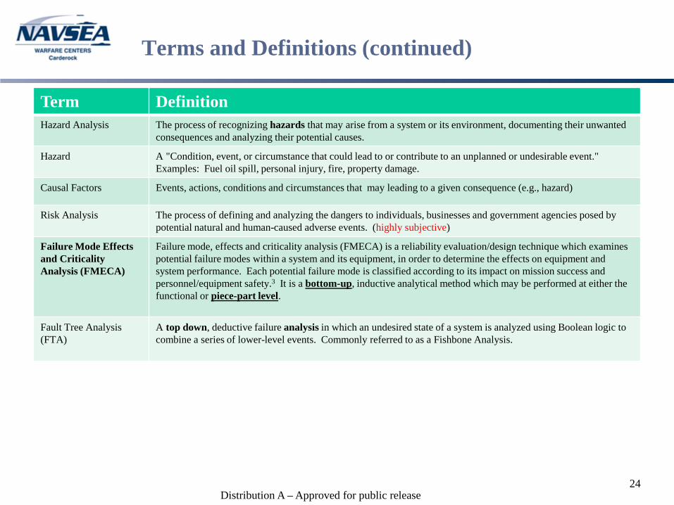
Terms and Definitions (continued)
Term DefinitionHazard Analysis The process of recognizing hazards that may arise from a system or its environment, documenting their unwanted
consequences and analyzing their potential causes.
Hazard A "Condition, event, or circumstance that could lead to or contribute to an unplanned or undesirable event." Examples: Fuel oil spill, personal injury, fire, property damage.
Causal Factors Events, actions, conditions and circumstances that may leading to a given consequence (e.g., hazard)
Risk Analysis The process of defining and analyzing the dangers to individuals, businesses and government agencies posed by potential natural and human-caused adverse events. (highly subjective)
Failure Mode Effects and Criticality Analysis (FMECA)
Failure mode, effects and criticality analysis (FMECA) is a reliability evaluation/design technique which examines potential failure modes within a system and its equipment, in order to determine the effects on equipment and system performance. Each potential failure mode is classified according to its impact on mission success and personnel/equipment safety.3 It is a bottom-up, inductive analytical method which may be performed at either the functional or piece-part level.
Fault Tree Analysis (FTA)
A top down, deductive failure analysis in which an undesired state of a system is analyzed using Boolean logic to combine a series of lower-level events. Commonly referred to as a Fishbone Analysis.
24
Distribution A – Approved for public release
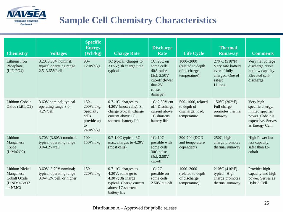
Sample Cell Chemistry Characteristics
25
Chemistry Voltages
Specific Energy (Wh/kg) Charge Rate
Discharge Rate Life Cycle
Thermal Runaway Comments
Lithium Iron Phosphate (LiFePO4)
3.20, 3.30V nominal; typical operating range 2.5–3.65V/cell
90–120Wh/kg
1C typical, charges to 3.65V; 3h charge time typical
1C, 25C on some cells; 40A pulse (2s); 2.50V cut-off (lower that 2V causes damage)
1000–2000 (related to depth of discharge, temperature)
270°C (518°F) Very safe battery even if fully charged. One of safestLi-ions.
Very flat voltage discharge curve but low capacity. Elevated self-discharge.
Lithium Cobalt Oxide (LiCoO2)
3.60V nominal; typical operating range 3.0–4.2V/cell
150–200Wh/kg.Specialty cells provide up to 240Wh/kg.
0.7–1C, charges to 4.20V (most cells); 3h charge typical. Charge current above 1C shortens battery life
1C; 2.50V cut off. Discharge current above 1C shortens battery life
500–1000, related to depth of discharge, load, temperature
150°C (302°F). Full charge promotes thermal runaway
Very high specific energy, limited specific power. Cobalt is expensive. Serves as Energy Cell.
Lithium Manganese Oxide (LiMn2O2)
3.70V (3.80V) nominal, typical operating range 3.0-4.2V/cell
100-150Wh/kg
0.7-1.0C typical, 3C max, charges to 4.20V (most cells)
1C; 10C possible with some cells, 30C pulse(5s), 2.50V cut-off
300-700 (DOD and temperature dependent)
250C, high charge promotes thermal runaway
High Power but less capacity:safer than Li-cobalt
Lithium Nickel Manganese Cobalt Oxide (LiNiMnCoO2 or NMC)
3.60V, 3.70V nominal; typical operating range 3.0–4.2V/cell, or higher
150–220Wh/kg
0.7–1C, charges to 4.20V, some go to 4.30V; 3h charge typical. Charge current above 1C shortens battery life
1C; 2C possible on some cells; 2.50V cut-off
1000–2000 (related to depth of discharge, temperature)
210°C (410°F) typical. High charge promotes thermal runaway
Provides high capacity and high power. Serves as Hybrid Cell.
Distribution A – Approved for public release
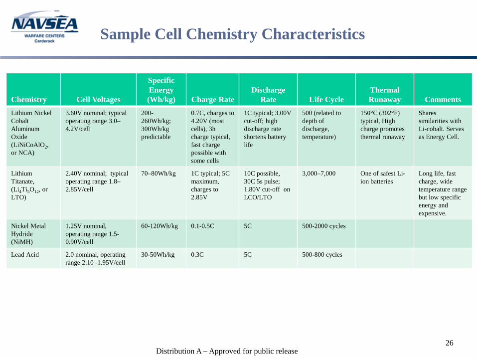
Sample Cell Chemistry Characteristics
26
Chemistry Cell Voltages
Specific Energy (Wh/kg) Charge Rate
Discharge Rate Life Cycle
Thermal Runaway Comments
Lithium Nickel Cobalt Aluminum Oxide (LiNiCoAlO2, or NCA)
3.60V nominal; typical operating range 3.0–4.2V/cell
200-260Wh/kg; 300Wh/kg predictable
0.7C, charges to 4.20V (most cells), 3h charge typical, fast charge possible with some cells
1C typical; 3.00V cut-off; high discharge rate shortens battery life
500 (related to depth of discharge, temperature)
150°C (302°F) typical, High charge promotes thermal runaway
Shares similarities with Li-cobalt. Serves as Energy Cell.
Lithium Titanate,(Li4Ti5O12, or LTO)
2.40V nominal; typical operating range 1.8–2.85V/cell
70–80Wh/kg 1C typical; 5C maximum, charges to 2.85V
10C possible, 30C 5s pulse; 1.80V cut-off on LCO/LTO
3,000–7,000 One of safest Li-ion batteries
Long life, fast charge, wide temperature range but low specific energy and expensive.
Nickel Metal Hydride (NiMH)
1.25V nominal, operating range 1.5-0.90V/cell
60-120Wh/kg 0.1-0.5C 5C 500-2000 cycles
Lead Acid 2.0 nominal, operating range 2.10 -1.95V/cell
30-50Wh/kg 0.3C 5C 500-800 cycles