Embed Size (px)
Citation preview
Switch Mode
BATTERY CHARGERFor lead-acid batteries 14-150 Ah
MULTI US 7000
User’s Manual and a guideto professional battery chargingFor Starter/Deep Cycle batteries
US
2
INTRODUCTIONThe MULTI US 7000 is a primary switch mode battery charger with pulse maintenance. The MULTI US 7000 is designed to offer maximum life for the battery. MULTI US 7000 is a member of a family of professional chargers from CTEK SWEDEN AB. It represents the state-of-the-art of today’s technology for battery charging. Please read these operating instructions carefully before operating the MULTI US 7000.
IMPORTANT SAFETY INSTRUCTIONS1. SAVE THESE INSTRUCTIONS – This manual contains
important safety and operating instructions for the MULTI US 7000 battery charger. 2. When charging, batteries can emit explosive gases, therefore it is essential
to prevent flames and sparks. The charger is designed for charging lead-acid batteries from 14 to 150 Ah. Do not use for any other purpose.
3. Always provide good ventilation when charging.4. Use of an attachment not recommended or sold by CTEK may result in a risk of
fire, electric shock or serious injury to persons.5. To reduce risk of damage to electric plug and cord, pull by the plug rather than by
the cord when disconnecting charger.6. An extension cord should not be used unless absolutely necessary. Use of an
improper extension cord could result in a risk of fire and electric shock. If extension cord must be used, make sure that: a) Pins on plug of extension cord are the same number, size and shape as those of plug on charger; b) Extension cord is properly wired and in good electrical condition; and c) Wire size is large enough for ac ampere rating as specified in “technical data”
7. Do not operate charger with a damaged cord or plug - return the charger to the place where purchased.
8. Never operate the charger if it has received a sharp blow, been dropped or otherwise damaged in any way; take it to a qualified serviceman.
9. Do not disassemble the charger; take it to a qualified serviceman when service or repair is required. Incorrect reassembly may result in a risk of electrical shock or fire.
10. To reduce risk of electric shock, unplug charger from AC outlet before attempting any maintenance or cleaning. Turning off controls will not reduce the risk.
3
11. WARNING - RISK OF EXPLOSIVE GASESa) BATTERIES GENERATE EXPLOSIVE GASES
DURING NORMAL BATTERY OPERATION. FOR THIS REASON, IT IS OF THE UTMOST IMPORTANCE THAT EACH TIME BEFORE USING YOUR CHARGER, YOU READ THIS MANUAL AND FOLLOW THE INSTRUCTIONS CAREFULLY.
b) Follow these instructions and those published by the battery manufacturer and the manufacturer of any equipment you intend to use in vicinity of battery.
12. PERSONAL PRECAUTIONSa) Some one should be within voice range or close enough to come to your aid when
you work near a lead-acid battery.b) Have plenty of fresh water and soap nearby in case battery acid contacts skin,
clothing or eyes.c) Always wear complete eye protection and clothing protection. Avoid touching eyes
while working near battery.d) If battery acid contacts skin or clothing, wash immediately with soap and water.
If acid enters eye, immediately flood eye with running cold water for at least 10 minutes and get medical attention immediately.
e) NEVER smoke or allow a spark or flame in vicinity of battery or engine.f) Be extra cautious to reduce risk of dropping a metal tool onto battery. It might
spark or short-circuit battery or other electrical part that may cause explosion.g) Remove personal metal items such as rings, bracelets, necklaces, and watches
when working with lead-acid battery. A lead-acid battery can produce a short-circuit current high enough to weld a ring or the like to metal, causing a severe burn.
h) Use charger for charging a LEAD-ACID battery only. Do not use battery charger for dry-cell batteries that are commonly used with home appliances. These batteries may burst and cause injury to persons and damage to property.
i) Never charge a frozen battery.
4
13. PREPARING TO CHARGEa) If necessary to remove battery from vehicle to charge, always remove grounded
terminal from battery first. Make sure all accessories in the vehicle are off, so as not to cause an arc.
b) Be sure area around battery is well ventilated while battery is being charged. Gas can be forcefully blown away by fanning the area with a piece of cardboard or other non-metallic material.
c) Clean battery terminals. Be careful to keep corrosion from coming in contact with eyes.
d) Add distilled water in each cell until battery acid reaches level specified by battery manufacturer. This helps to purge excessive gas from cells. Do not overfill. For a battery without cell caps, carefully follow manufacturer’s recharging instruction.
e) Study battery manufacturer’s specific precautions such as removing or not removing cell caps while charging.
f) Determine voltage of battery by referring to car owner’s manual and make sure that the output voltage selector switch is set at correct voltage.
14. CHARGER LOCATIONa) Locate charger as far away from the battery as battery charger cables permit.b) Never place charger directly above battery being charged; gases from battery will
corrode and damage charger.c) Never allow battery acid to drip on charger.d) Do not operate charger in a closed-in area or restrict ventilation in any way.e) Do not set a battery on top of charger.
15. DC CONNECTION PRECAUTIONSa) Connect and disconnect dc output clips only after setting any charger switches to
off position and removing ac cord from electric outlet. Never allow clips to touch each other.
b) Attach clips to battery and chassis as indicated in 16(e), 16(f), 17(b) and 17(d).
16. FOLLOW THESE STEPS WHEN BATTERY IS INSTALLED IN VEHICLE. A SPARK NEAR BATTERY MAY CAUSE BATTERY EXPLOSION. TO REDUCE RISK OF A SPARK NEAR BATTERY:
a) Position ac and dc cord in a safe position to reduce risk of damage by hood, door or moving engine part.
5
b) Stay clear of fan blades, belts, pulleys, and other parts that can cause injury to persons.
c) Check polarity of battery terminals. POSITIVE (POS, P, +) battery post usually has larger diameter than NEGATIVE (NEG, N, -) post.
d) Determine which post of battery is grounded (connected) to the chassis. If negative post is grounded to the chassis (as in most vehicles) see (e). If positive post is grounded to the chassis, see (f).
e) Negative-grounded vehicle. Charger connection.
1. Connect positive charger clip (red) to positive battery terminal. 2. Connect negative charger clip (black) to a good metal engine ground away
from the battery. Do no connect clip to fuel lines or sheet-metal body parts. 3. Connect the AC cord to the socket. The red alarm indication light will indicate a
battery which is connected to reverse polarity.f) Positive grounded vehicle Charger connection. 1. Connect negative charger clip (black) to negative battery terminal. 2. Connect positive charger clip (red) to a good metal engine ground away from
the battery. Do no connect clip to fuel lines or sheet-metal body parts. 3. Connect the AC cord to the socket. The red alarm indication light will indicate
a battery which is connected to reverse polarity.g) When disconnecting charger, disconnect AC cord, remove clip from vehicle
chassis, and then remove clip from battery terminal.h) See operating instructions for charge information.
17. FOLLOW THESE STEPS WHEN BATTERY IS OUTSIDE VEHICLE. A SPARK NEAR BATTERY MAY CAUSE BATTERY EXPLOSION. TO REDUCE RISK OF A SPARK NEAR BATTERY:
a) Check polarity of battery terminals. POSITIVE (POS, P, +) battery post usually has larger diameter than NEGATIVE (NEG, N, -) post.
b) Connect POSITIVE (RED) charger clip to POSITIVE (POS, P, +) battery post. c) Connect NEGATIVE (Black) charger clip to NEGATIVE (NEG,N,-) battery post.
The red alarm indication light will indicate a battery, which is connected to reverse polarity.
d) Connect charger’s AC cord to socket.
6
e) Do not face the battery when making the final connection.f) When disconnecting charger, disconnect in reverse sequence from connecting
procedure. See operating instructions for charge information.The battery charger must be connected to the battery according to the instructions above.
IMPORTANT SAFETY INFORMATION!The MULTI US 7000 cannot be used to restore a fully worn out battery. If the MULTI US 7000 does not switch to maintenance charge after three days (green light illuminated), there is a fault. Possible causes: • The battery is probably worn out and should be replaced. • Some large antimony batteries may behave differently and can allow the MULTI US 7000 to charge the battery for too long, which can lead to overcharging. See caution!• If heavy power consumers like fitted alarms and navigation computers are connected to the battery, the charging process takes longer and this can also overcharge the battery. • A sulphated battery will only accept current with difficulty, and consequently the charging process takes a particularly long time. A worn out battery cannot be fully charged. Therefore you should always check whether the charger has been switched to maintenance charge before you leave it turned on or unobserved for any length of time. Caution: If the MULTI US 7000 does not switch to maintenance mode after three days, manually switch it to pulse maintenance mode. If the set has been switched to maintenance charge, then everything is in order. Note: A battery that hasn’t changed to maintenance charge after three days is most likely worn out and needs to be replaced. All other batteries can be maintained for a very long time.
CHARGINGConnecting the MULTI US 7000: - Connecting the equipment to a battery fitted in the vehicle: 1. When the battery cable is being connected or disconnected, the plug of the MULTI US 7000 must be disconnected from the power socket.2. Establish which terminal is ground (connected to the chassis). Normally the negative terminal is grounded.3. Charging a battery grounded to the negative terminal: Negative-grounded vehicleCharger connection. 1. Connect positive charger clip (red) to positive battery terminal. 2. Connect negative charger clip (black) to a good metal engine ground
away from the battery. Do not connect clip to fuel lines or sheet-metal body parts. 3. Connect the AC cord to the socket. The red alarm indication light will indicate a
battery which is connected to reverse polarity.
7
4. Charging a battery grounded to the positive terminal: Positive grounded vehicle Charger connection. 1. Connect negative charger clip (black) to negative battery terminal. 2. Connect positive charger clip (red) to a good metal engine ground away from
the battery. Do not connect clip to fuel lines or sheet-metal body parts. 3. Connect the AC cord to the socket. The red alarm indication light will indicate a
battery which is connected to reverse polarity.Connecting the MULTI US 7000 to an out of vehicle battery: a) Check polarity of battery terminals. POSITIVE (POS, P, +) battery post usually
has larger diameter than NEGATIVE (NEG, N, -) post.b) Connect POSITIVE (RED) charger clip to POSITIVE (POS, P, +) battery post. c) Connect NEGATIVE (Black) charger clip to NEGATIVE (NEG, N, -) battery post.
The red alarm indication light will indicate a battery, which is connected to reverse polarity.
d) Connect charger’s AC cord to socket. e) Do not face the battery when making the final connection.f) When disconnecting charger, disconnect in reverse sequence from
connecting procedure. See operating instructions for charge information.Starting the charging process1. Set the correct charge mode by pressing the mode button for motorcycle or car. You can find out how to select the correct charge mode to be used for charging your battery in the section on “SETTINGS”. 2. Once you have established that the battery cable has been correctly connected you can start the charging process. To do so, insert the charger plug into the AC socket.3. Now either the charge indicator or the maintenance charge indicator lights up. When the maintenance charge indicator lights up, the battery is fully charged. If the battery voltage drops, the charger sends a pulse to the battery. The length of the pulse depends on how much charge the battery has lost. The MULTI US 7000 may be con-nected for months at a time. However it is recommended to monitor batteries on charge.4. If nothing happens: If the indicator for the set voltage is still illuminated, but no other indicator is illuminated, the connection to the battery or the chassis could be faulty, or the battery could be defective. If the charging process has not started, this could be due to the fact that the power socket is not supplying a current. 5. The charging process can be interrupted at any time. In addition pull the plug of the charger out of the power socket or put the charger on Stand-by/Power On . Always remove the plug of the charger from the power socket before disconnecting the battery cable. If you interrupt the charging process of a battery fitted in a vehicle, the battery cable must always be first disconnected from the chassis and then from the other battery cable.
8
6. If the indicator for charge and maintenance charge are flashing alternately, this may have the following causes: • Interruption of the charging process because a cable has become loose or because the battery is not conducting. • The battery is sulphated. If the indicator flashes for more than 30 minutes the battery may be defective and should be replaced.• If the flashing signal is flashing at intervals of more than 10 seconds, then there is a high self discharge of the battery, indicating a bad battery.
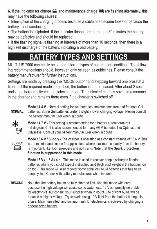
BATTERY TYPES AND SETTINGSMULTI US 7000 can easily be set for different types of batteries or conditions. The follow-ing recommendations should, however, only be seen as guidelines. Please consult the battery manufacturer for further instructions. Settings are made by pressing the ”MODE-button” and stepping forward one press at a time until the required mode is reached, the button is then released. After about 2 sec-onds the charger activates the selected mode. The selected mode is saved in a memory in the charger and remains there even if the charger is switched off.
NORMALMode 14.4 V - Normal setting for wet batteries, maintenance free and for most Gel batteries. Some Gel batteries prefer a slightly lower charging voltage. Please consult the battery manufacturer when in doubt.
Mode 14.7 V - This setting is recommended for a battery at temperatures < 5 degrees C. It is also recommended for many AGM batteries like Optima, and Odysseys. Consult your battery manufacturer when in doubt.
SUPPLYMode 13.6 V / Supply - The charger is operating at a constant voltage of 13.6 V. This is the maintenance mode for applications where maximum capacity from the battery is important, like floor sweepers and golf carts. Note that the Spark protection function is suppressed in this mode.
RECOND
Mode 16 V / 1.5 A / 4 h - This mode is used to recover deep discharged flooded batteries where you could expect a stratified acid (high acid weight in the bottom, low on top). This mode will also recover some spiral cell AGM batteries that has been deep cycled. Check with battery manufacturer when in doubt.
Note that the battery has to be fully charged first. Use this mode with care, because the high voltage will cause some water loss. 16 V is normally no problem for electronics, but consult your supplier when in doubt. Life of light bulbs will be reduced at higher voltage. Try to avoid using 12 V light from the battery during this phase. Maximum effect and minimum risk for electronics is achieved by charging a disconnected battery.
9
CHARGINGThe battery charger must be connected to the battery according to the instructions above. Start charging1. Connect the power cord to the power outlet. The charger indicates STANDBY, or latest
selected mode, yellow indication light (A).2. Set the proper charging mode for the battery by pushing the Mode Selector Button (see
Battery Types and Settings).3. The lamp for Deep Discharged battery (1) will indicate if the battery has been dis-
charged down to below 10.5 V. A recondition phase could be needed after the com-pleted charge cycle.
4. Normal charging settings (14.4 V or 14.7 V) will be indicated by the lamps for Deep Discharged (1), Bulk Charge (2), Absorption Charge (3) or Maintenance Charge (4). The lamp for maintenance means that the battery is fully charged. The charge will restart if the voltage drops. The charger can normally be connected for months. How-ever it is recommended to monitor batteries on charge. The Supply or Recond settings are indicated by the lamps for those settings.
5. The red alarm indication light (0) will indicate a battery, which is connected to reverse polarity (will not work in Supply Mode). The red alarm indication light (0) will also indi-cate if the charge cycle is activated without any battery connected to the battery leads.
6. If nothing happens: A bad connection of the battery to ground will be indicated by no indicator lights illuminating or that the indicator lamp is still in the Standby-mode (lamp A). A bad battery will also be indicated in the same way. Don’t forget to check the wall outlet. If you experience problems: start with the sensitive connection between the bat-tery clamps and the charger.
7. A flickering between the lamps for charging and fully charged could be caused by several reasons.
a. A lost connection. This is most likely in the cabling but could also be internal. Put the charger in STANDBY and try to restart.
b. A lightly sulphated battery. The flickering will end within 60 minutes if the battery could be recovered. The battery cannot be recharged if the flickering continues.
c. A battery with high self discharge could be seen when the Fully charged lamp is on for 10 seconds and more, combined with a short Charge indication. Such a battery is at the end of its life and needs to be replaced.
8. The charging could be interrupted at any time by disconnecting the supply cord or by setting the charger in Stand by. Removing the ground lead first when disconnecting the battery leads from a battery in a vehicle.
10
CHARGING CYCLEVo
ltage
/Cur
rent
Voltage
Time
Current
BulkIo
StartIs
AbsorptionUo
PulseUp
SupplyUo
RecondI
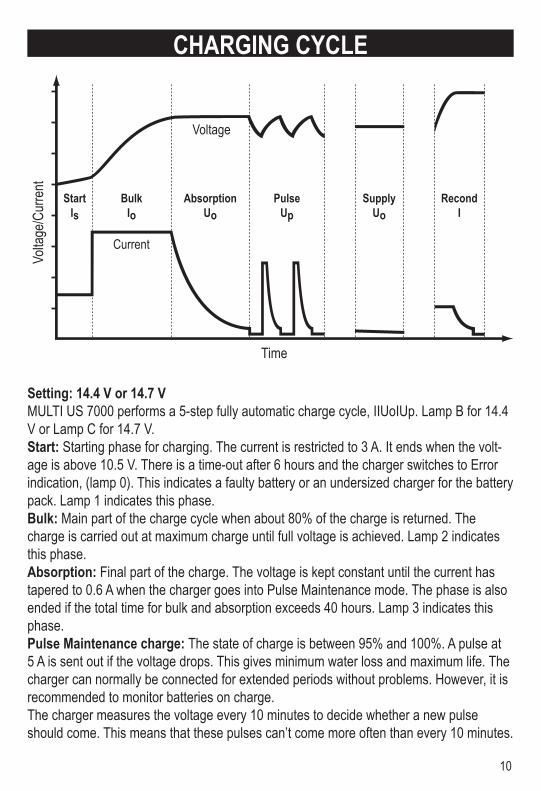
Setting: 14.4 V or 14.7 VMULTI US 7000 performs a 5-step fully automatic charge cycle, IIUoIUp. Lamp B for 14.4 V or Lamp C for 14.7 V.Start: Starting phase for charging. The current is restricted to 3 A. It ends when the volt-age is above 10.5 V. There is a time-out after 6 hours and the charger switches to Error indication, (lamp 0). This indicates a faulty battery or an undersized charger for the battery pack. Lamp 1 indicates this phase.Bulk: Main part of the charge cycle when about 80% of the charge is returned. The charge is carried out at maximum charge until full voltage is achieved. Lamp 2 indicates this phase.Absorption: Final part of the charge. The voltage is kept constant until the current has tapered to 0.6 A when the charger goes into Pulse Maintenance mode. The phase is also ended if the total time for bulk and absorption exceeds 40 hours. Lamp 3 indicates this phase.Pulse Maintenance charge: The state of charge is between 95% and 100%. A pulse at 5 A is sent out if the voltage drops. This gives minimum water loss and maximum life. The charger can normally be connected for extended periods without problems. However, it is recommended to monitor batteries on charge. The charger measures the voltage every 10 minutes to decide whether a new pulse should come. This means that these pulses can’t come more often than every 10 minutes.
11
If the battery is charged and/or the battery's terminal voltage drops below 12.9 V the char-ger starts a charge pulse of 5A until the terminal voltage has reached the set level, 14.4 V or 14.7 V. The charge pulse is then interrupted and the cycle is repeated as long as the charger is in pulse maintenance phase. Pulse maintenance phase is indicated by lamp 4. If the terminal voltage drops below 12.1 V, the charger automatically reverts to the begin-ning of the charging curve.Setting : Supply 13.6 VMULTI US 7000 has a Supply mode setting which has a constant voltage at 13.6 V and current up to 7 A. It could be used for maintenance charge using the Float approach. This approach keeps the battery at 100 % State of Charge, but the constant small overcharge also increases water loss. Note that there is no need for a battery to be connected at this mode. Note: The Spark protection system and the indication of Reverse Polarity is suppressed in this mode. The Short Circuit protection is still working.It is not advisable to charge a discharged battery in Supply mode as this will not provide a complete charge. In this mode, MULTI US 7000 can also be used as a power-generation unit for operating equipment that requires 13.6 V and a maximum of 7 A. If the selected current exceeds 7 A, the output voltage will drop at an increasing rate. The charger has electronic overload protection in this mode, which is activated if the charge is so great that the output voltage from the charger falls below around 3.5 V and the current to around 7 A. In the event of an overload, the charger transfers to error mode (lamp 0).Setting lamp D indication lamp 5.Setting: Recond 16 V / 1.5 A / 4 hMULTI US 7000 has a Recond-setting which gives a constant current at 1.5 A, maximised at 16 V for 4 hours. It will automatically go over to 14.4 V pulse setting after a completed cycle. This mode is used for batteries that have been deep discharged. Start by charging at either the 14.4 V or 14.7 V setting until the battery is in Pulse maintenance phase. Set-ting lamp E indication lamp 6.
12
INDICATORS
SUPPLYNORMAL
SUPPLY
RECOND
RECOND
MODE
10
A B C D E
23 4
5
6
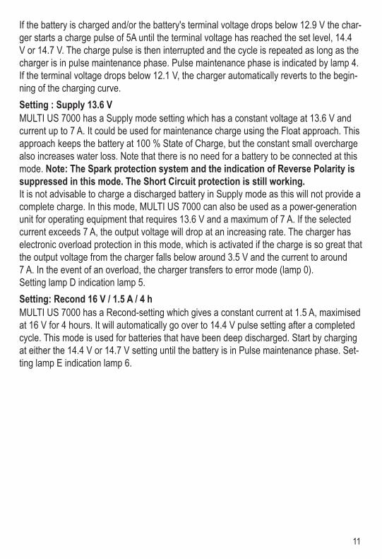
Indication Description0 Error mode, the charger interrupts the charging/voltage supply. See description
below.1 Start mode, restricted charging current and battery voltage under 10.5 V.2 Bulk charging, Maximum charging current.3 Absorption charging, Voltage restrictions to selected voltage.4 Charging completed. Pulse maintenance charging.5 Supply mode, fixed output voltage, no counter voltage requirements.6 Recond charging in progress, constant current 1.5 A.A STANDBY - Power on no selection done,B Mode 14.4 V - See battery types and settings.C Mode 14.7 V - See battery types and settings.D Mode 13.6 V / Supply - See battery types and settings.E Mode 16 V / 1.5 A / 4 h Recond - See battery types and settings.
Error mode The charger goes to error mode in the following situations:1. Charging is started without a battery with terminal voltage over 1.5 V being con-
nected to the terminals.2. The battery is connected with the battery´s terminals reversed to the charger's
terminals.3. The terminals on the charger are short-circuited when charging has started.4. The charger is overloaded in Supply mode.5. The charger has been in start mode for more than 6 hours.6. If the total time for bulk and absorption exceeds 40 hours. Error mode is acknowledged/reset by pressing ”the MODE” button. The charger
restarts in the latest selected mode.
13
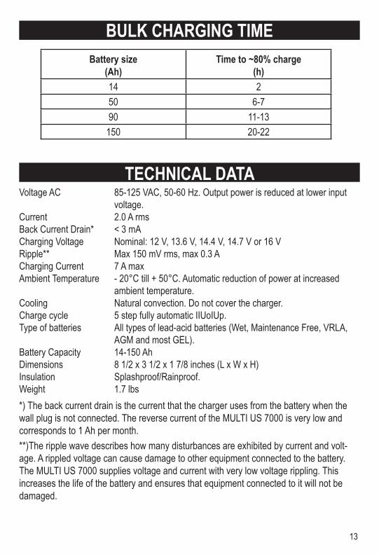
BULK CHARGING TIMEBattery size
(Ah)Time to ~80% charge
(h)14 250 6-790 11-13
150 20-22
TECHNICAL DATAVoltage AC 85-125 VAC, 50-60 Hz. Output power is reduced at lower input
voltage. Current 2.0 A rmsBack Current Drain* < 3 mACharging Voltage Nominal: 12 V, 13.6 V, 14.4 V, 14.7 V or 16 VRipple** Max 150 mV rms, max 0.3 A Charging Current 7 A maxAmbient Temperature - 20°C till + 50°C. Automatic reduction of power at increased
ambient temperature. Cooling Natural convection. Do not cover the charger.Charge cycle 5 step fully automatic IIUoIUp.Type of batteries All types of lead-acid batteries (Wet, Maintenance Free, VRLA,
AGM and most GEL).Battery Capacity 14-150 Ah Dimensions 8 1/2 x 3 1/2 x 1 7/8 inches (L x W x H)Insulation Splashproof/Rainproof.Weight 1.7 lbs*) The back current drain is the current that the charger uses from the battery when the wall plug is not connected. The reverse current of the MULTI US 7000 is very low and corresponds to 1 Ah per month. **)The ripple wave describes how many disturbances are exhibited by current and volt-age. A rippled voltage can cause damage to other equipment connected to the battery. The MULTI US 7000 supplies voltage and current with very low voltage rippling. This increases the life of the battery and ensures that equipment connected to it will not be damaged.
14
OVERHEATING PROTECTIONThe MULTI US 7000 is equipped with overheating protection. In high ambient tempera-tures the output power is reduced. Do not cover the charger.
BATTERY CABLESMulti US 7000 is equipped with a set of battery cables with battery terminal clips and one set of battery cables with eyelet terminals.
MAINTENANCEThe MULTI US 7000 is maintenance-free. The charger must not be opened; doing so will invalidate the warranty. If the power cable is damaged it must be replaced by CTEK or its authorized representative. The charger casing can be cleaned using a damp cloth and mild cleaning agent. Remove the plug from the power socket before cleaning.
LIMITED WARRANTYCTEK SWEDEN AB, Rostugnsv. 3, SE-776 70 VIKMANSHYTTAN, SWEDEN issues this limited warranty to the original purchaser of this product. This limited warranty is not trans-ferable. CTEK SWEDEN AB warrants this unit for two years from the date of purchase against defect workmanship or material. It is the obligation of the purchaser to forward the unit together with proof of purchase to the manufacturer or its representative with transportation cost prepaid. This warranty is void if the unit is abused, handled carelessly or repaired by anyone other than CTEK SWEDEN AB or its authorized representative. CTEK SWEDEN AB makes no warranty other than this limited warranty and expressly excludes any implied warranty including any warranty for consequential damages. This is the only expressed limited warranty and CTEK SWEDEN AB neither assumes nor authorizes anyone to assume or make any other obligation towards the product other than this limited warranty.
CTEK SWEDEN ABRostugnsvägen 3SE-776 70 VIKMANSHYTTANSWEDENFax: + 46 225 307 93www.ctek.com